1
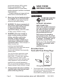
COMPRESSOR AND
AIR BRUSH KIT
Model 95630
SET UP AND OPERATING INSTRUCTIONS
Visit our website at: http://www.harborfreight.com
Read and understand tool labels and
manual. Failure to follow warnings could
result in DEATH or SERIOUS INJURY.
SAVE THIS MANUAL.
Copyright© 2010 by Harbor Freight Tools®. All rights reserved. No portion of this manual or any artwork
contained herein may be reproduced in any shape or form without the express written consent of
Harbor Freight Tools. Diagrams within this manual may not be drawn proportionally. Due to continuing
improvements, actual product may differ slightly from the product described herein. Tools required for
assembly and service may not be included.
For technical questions or replacement parts, please call 1‑800‑444‑3353.
SAVE THIS MANUAL
Keep this manual for the safety warnings
and precautions, assembly, operating,
inspection, maintenance and cleaning
procedures. Write the product’s serial number
in the back of the manual near the assembly
diagram (or month and year of purchase if
product has no number). Keep this manual
and the receipt in a safe and dry place for
future reference.
Safety Alert Symbol and Signal
Words
In this manual, on the labeling, and
all other information provided with
this product:
This is the safety alert
symbol. It is used to alert
you to potential personal
injury hazards. Obey all
safety messages that follow
this symbol to avoid possible
injury or death.
DANGER indicates a
hazardous situation
which, if not avoided, will result
in death or serious injury.
WARNING indicates a
hazardous situation
which, if not avoided, could
result in death or serious injury.
CAUTION, without the
safety alert symbol, is
used to address practices not
related to personal injury.
Symbol Definitions
Symbol
PSI
CFM
SCFM
Property or statement
Pounds per square inch of pressure
Cubic Feet per Minute flow
Cubic Feet per Minute flow at standard
conditions
NPT
National pipe thread, tapered
NPS
National pipe thread, straight
WARNING marking concerning Risk of
Eye Injury. Wear ANSI-approved safety
goggles with side shields.
Read the manual before set-up and/or
use.
WARNING marking concerning Risk of
Hearing Loss. Wear hearing protection.
WARNING marking concerning Risk
of Respiratory Injury. Wear NIOSHapproved dust mask/respirator.
WARNING marking concerning Risk of
Explosion.
CAUTION, used with
the safety alert
symbol, indicates a hazardous
situation which, if not avoided,
could result in minor or moderate
injury.
NOTICE is used to
address practices not
related to personal injury.
Page 2
Important
Safety Instructions
IMPOINSTRUCTIONS
INSTRUCTIONS PERTAINING
TO A RISK OF FIRE, ELECTRIC
SHOCK, OR INJURY
TO PERSONS
WARNING – When using tools, basic
precautions should always be followed,
including the following:
For technical questions, please call 1-800-444-3353.
SKU 95630
moving parts. Damaged or entangled
cords increase the risk of electric shock.
General
a.
To reduce the risks of electric shock,
fire, and injury to persons, read all the
instructions before using the tool.
e.
When operating a power tool
outdoors, use an extension cord
suitable for outdoor use. Use of a cord
suitable for outdoor use reduces the risk
of electric shock.
f.
If operating a power tool in a damp
location is unavoidable, use a Ground
Fault Circuit Interrupter (GFCI)
protected supply. Use of a GFCI
reduces the risk of electric shock.
Work area
a.
Keep the work area clean and well
lighted. Cluttered benches and dark
areas increase the risks of electric
shock, fire, and injury to persons.
b.
Do not operate the tool in explosive
atmospheres, such as in the presence
of flammable liquids, gases, or dust.
The tool is able to create sparks resulting
in the ignition of the dust or fumes.
c.
Personal safety
a.
Stay alert. Watch what you are
doing and use common sense when
operating the tool. Do not use the
tool while tired or under the influence
of drugs, alcohol, or medication. A
moment of inattention while operating
the tool increases the risk of injury to
persons.
b.
Dress properly. Do not wear loose
clothing or jewelry. Contain long hair.
Keep hair, clothing, and gloves away
from moving parts. Loose clothes,
jewelry, or long hair increases the risk
of injury to persons as a result of being
caught in moving parts.
c.
Avoid unintentional starting. Be
sure the Power Switch if off before
connecting to the air supply. Do not
carry the tool with your finger on the
Power Switch or connect the tool to the
air supply with the trigger pressed.
d.
Do not overreach. Keep proper
footing and balance at all times.
Proper footing and balance enables
better control of the tool in unexpected
situations.
Keep bystanders, children, and
visitors away while operating the tool.
Distractions are able to result in the loss
of control of the tool.
Electrical Safety
a.
Power tool plugs must match the
outlet. Never modify the plug in
any way. Do not use any adapter
plugs with grounded power tools.
Unmodified plugs and matching outlets
will reduce risk of electric shock.
b.
Avoid body contact with grounded
surfaces such as pipes, radiators,
ranges and refrigerators. There is an
increased risk of electric shock if your
body is grounded.
c.
Do not expose power tools to rain or
wet conditions. Water entering a power
tool will increase the risk of electric
shock.
d.
Do not abuse the cord. Never use
the cord for carrying, pulling or
unplugging the power tool. Keep cord
away from heat, oil, sharp edges or
SKU 95630
For technical questions, please call 1-800-444-3353.
Page 3
e.
Use safety equipment. A
dust mask, non-skid safety
shoes and a hard hat must be
used for the applicable
conditions. Wear heavy-duty work
gloves during use.
Always wear eye protection.
Wear ANSI-approved safety
goggles with side shields.
f.
g.
Always wear hearing
protection when using the
tool. Prolonged exposure to
high intensity noise is able to
cause hearing loss.
persons. A tool is dangerous in the
hands of untrained users.
f.
Maintain the tool with care. A properly
maintained tool reduces the risk of
binding and is easier to control.
g.
Check for misalignment or binding
of moving parts, breakage of parts,
and any other condition that affects
the tool’s operation. If damaged,
have the tool serviced before using.
Many accidents are caused by poorly
maintained tools. There is a risk of
bursting if the tool is damaged.
h.
Use only accessories that are
identified by the manufacturer for
the specific tool model. Use of an
accessory not intended for use with the
specific tool model, increases the risk of
injury to persons.
Tool use and care
a.
b.
Use clamps or another practical way
to secure and support the workpiece
to a stable platform. Holding the work
by hand or against the body is unstable
and can lead to loss of control.
Do not force the tool. Use the correct
tool for the application. The correct tool
will do the job better and safer at the rate
for which the tool is designed.
c.
Do not use the tool if the Power
Switch does not turn the tool on or
off. Any tool that cannot be controlled
with the Power Switch is dangerous and
must not be used until repaired.
d.
Disconnect the tool from the air
source before making adjustments,
doing tool maintenance, clearing
jams, touching the safety nosepiece,
leaving work area, loading, or
unloading the tool. Such precautionary
measures reduce the risk of injury to
persons.
e.
Store the tool when it is idle out of
reach of children and other untrained
Page 4
Service
a.
Tool service must be performed only
by qualified repair personnel.
b.
When servicing a tool, use only
identical replacement parts. Use only
authorized parts.
SAVE THESE
INSTRUCTIONS.
For technical questions, please call 1-800-444-3353.
SKU 95630
Specific
Safety Instructions
SPECIFIC
SAFETY
1.
2.
3.
4.
S
Maintain labels and nameplates on the
tool. These carry important information.
If unreadable or missing, contact Harbor
Freight Tools for a replacement.
DANGER! This Air Compressor is
NOT equipped and should not be used
“as is” to supply breathing quality air.
For any application of air for human
consumption, you must fit the Air
Compressor with suitable in-line safety
and alarm equipment (not included).
This additional equipment is necessary
to properly filter and purify the air to
meet minimal specifications for Grade D
breathing as described in Compressed
Gas Association Commodity
Specification G 7.1-1966, OSHA 29 CFR
1910. 134, and/or Canadian Standards
Associations (CSA).
Make sure all tools and equipment
used with the Air Compressor are
rated to the appropriate capacity.
Do not use any tool or equipment that
operates above 58 PSI.
Drain the Air Compressor everyday.
Do not allow excessive moisture to build
up inside the Air Compressor. Do not
open the Water Drain Valve (23) with
more than 10 PSI of air pressure in the
Compressor.
5.
Avoid injury. Do not direct compressed
air at people of animals. Do not direct
airflow at eyes or ears.
6.
Make sure the Air Compressor is
located on a flat, level, sturdy surface
capable of supporting the weight of
the Compressor and any additional
tools and equipment.
7.
Industrial applications must follow
OSHA guidelines.
SKU 95630
8.
Do not stand or sit on the Air
Compressor. Serious injury could result
if the Compressor is tipped.
9.
Do not leave the Air Compressor
unattended when it is plugged in.
Turn off the Compressor and unplug
before leaving.
10. Do not move or transport the
Air Compressor if the unit is
under pressure.
11. Do not force the Air Compressor.
This tool will do the work better and safer
at the speed and capacity for which it
was designed.
12. This Air Compressor will
automatically shut off on overload
or under excessive heat. Should
this occur, turn the Power Switch (34)
to its “OFF” position. Wait until the
Air Compressor cools. Then turn the
Power Switch (34) to its “ON” position to
resume work.
13. Spray painting only. Do not use this Air
Compressor with gasoline, kerosene, or
any other flammable solvent.
14. Maintain a safe working environment.
Make sure there is adequate
surrounding workspace. Do not use
this product in a damp or wet location.
15. People with pacemakers should
consult their physician(s) before
using this product. Electromagnetic
fields in close proximity to a heart
pacemaker could cause interference to
or failure of the pacemaker. In addition,
people with pacemakers should adhere
to the following:
• Avoid operating power tools alone.
• Don’t use a power tool with the power
switch locked on.
• If powered via a power cord be certain
that the tool is properly grounded. A
For technical questions, please call 1-800-444-3353.
Page 5
ground fault interrupt (GFCI) system
is also a good precaution. This
inexpensive device is a good safety
measure because it prevents a sustained
electrical shock.
• Properly maintain and inspect all tools
before use to avoid electrical shock
SAVE THESE
INSTRUCTIONS.
Groun
ding
Grounding
16. Never leave the tool unattended when
it is plugged into an electrical outlet.
Turn off the tool, and unplug it from its
electrical outlet before leaving.
TO PREVENT ELECTRIC
SHOCK AND DEATH
FROM
INCORRECT GROUNDING
WIRE CONNECTION:
Check with a qualified electrician
if you are in doubt as to whether
the outlet is properly grounded.
Do not modify the power cord
plug provided with the tool.
Never remove the grounding
prong from the plug. Do not use
the tool if the power cord or plug
is damaged. If damaged, have it
repaired by a service facility
before use. If the plug will not fit
the outlet, have a proper outlet
installed by a
qualified electrician.
17. WARNING: The brass components of
this product contain lead, a chemical
known to the State of California
to cause birth defects (or other
reproductive harm). (California Health
& Safety code § 25249.5, et seq.)
18. WARNING: Some dust created by
power sanding, sawing, grinding,
drilling, and other construction
activities, contains chemicals
known [to the State of California] to
cause cancer, birth defects or other
reproductive harm. Some examples of
these chemicals are:
Lead from lead-based paints
Crystalline silica from bricks and cement
or other masonry products
Arsenic and chromium from chemically
treated lumber
Your risk from these exposures varies,
depending on how often you do this
type of work. To reduce your exposure
to these chemicals: work in a well
ventilated area, and work with approved
safety equipment, such as those dust
masks that are specially designed to
filter out microscopic particles. (California
Health & Safety Code § 25249.5, et seq.)
19. Always maintain adequate ventilation,
especially when using solvent based
paints and during clean up.
Page 6
Grounded Tools:
Tools with Three Prong Plugs
3-Prong Plug and Outlet
1.
Tools marked with “Grounding Required”
have a three wire cord and three prong
grounding plug. The plug must be
connected to a properly grounded outlet.
For technical questions, please call 1-800-444-3353.
SKU 95630
2.
3.
If the tool should electrically malfunction
or break down, grounding provides a
low resistance path to carry electricity
away from the user, reducing the risk
of electric shock. (See 3-Prong Plug
and Outlet.)
2.
The grounding prong in the plug is
connected through the green wire inside
the cord to the grounding system in the
tool. The green wire in the cord must
be the only wire connected to the tool’s
grounding system and must never be
attached to an electrically “live” terminal.
(See 3-Prong Plug and Outlet.)
1.
Grounded tools require a three wire
extension cord. Double Insulated
tools can use either a two or three wire
extension cord.
2.
As the distance from the supply outlet
increases, you must use a heavier gauge
extension cord. Using extension cords
with inadequately sized wire causes a
serious drop in voltage, resulting in loss
of power and possible tool damage.
(See Table A on page <?>.)
3.
If you are using an extension cord
outdoors, make sure it is marked with the
suffix “W-A” (“W” in Canada) to indicate it
is acceptable for outdoor use.
4.
Protect the extension cords from sharp
objects, excessive heat, and damp or
wet areas
The tool must be plugged into an
appropriate outlet, properly installed
and grounded in accordance with all
codes and ordinances. The plug and
outlet should look like those in the
preceding illustration.
(See 3-Prong Plug and Outlet.)
Double Insulated Tools:
Tools with Two Prong Plugs
Double insulated tools may be used in
either of the 120 volt outlets shown in the
preceding illustration.
(See Outlets for 2-Prong Plug.)
Extension Cords
Table A: RECOMMENDED MINIMUM
WIRE GAUGE FOR EXTENSION CORDS*
(120/240 VOLT)
NAMEPLATE
AMPERES
(at full load)
Outlets for 2-Prong Plug
1.
Tools marked “Double Insulated” do not
require grounding. They have a special
double insulation system which satisfies
OSHA requirements and complies with
the applicable standards of Underwriters
Laboratories, Inc., the Canadian
Standard Association, and the National
Electrical Code.
SKU 95630
EXTENSION CORD
LENGTH
25´ 50´ 75´ 100´ 150´
0 – 2.0
18
18
18
18
16
2.1 – 3.4
18
18
18
16
14
3.5 – 5.0
18
18
16
14
12
5.1 – 7.0
18
16
14
12
12
7.1 – 12.0
18
14
12
10
-
12.1 – 16.0
14
12
10
-
-
16.1 – 20.0
12
10
-
-
-
* Based on limiting the line voltage drop to five volts at
150% of the rated amperes.
For technical questions, please call 1-800-444-3353.
Page 7
Description
Functional Description
Symbology
Double Insulated
Type
Single cylinder, oiless piston
Power
1/5 HP
Underwriters Laboratories, Inc.
Voltage
120, 60HZ, 1.18 AMP
Volts Alternating Current
Thermo-Overload
shutoff protection
Auto shutoff
Air output
0 - 58 PSI
Air outlet size
1/8 - 27 NPT male threads
Motor RPM
1750
Pressure Gauge
0-100 PSI
Cord length
6’-2 1/2”L
Canadian Standards Association
V~
A
Compressor Specifications
Amperes
No Load Revolutions per Minute
n0 xxxx/min. (RPM)
WARNING marking
concerning Risk of Eye Injury.
Wear ANSI‑approved safety
goggles with side shields.
Read the manual before set-up
and/or use.
WARNING marking concerning
Risk of Hearing Loss.
Wear hearing protection.
WARNING marking concerning
Risk of Fire.
Do not cover ventilation ducts.
Keep flammable objects away.
WARNING marking concerning
Risk of Electric Shock.
Properly connect power cord to
appropriate outlet.
Air Brush Specifications
Working Air
Pressure
0.5 CFM @ 20 PSI
Air Hose length
Approx. 5FT
Housing
Anodized Aluminum
22cc Glass jar assembly
Accessories
5cc Metal cup
Metal Hanger
INITIAL ASSEMBLY
Read the ENTIRE IMPORTANT
SAFETY INFORMATION
section at the beginning of this
manual including all text under
subheadings therein before set up
or use of this product.
Note: For additional information regarding
parts listed in following pages, refer to
Assembly Diagrams near end of manual.
Unpacking
When unpacking, make sure that the
item is intact and undamaged. If any parts
are missing or broken, please call Harbor
Freight Tools at 1‑800‑444‑3353 as soon
as possible.
Page 8
For technical questions, please call 1-800-444-3353.
SKU 95630
tripping hazard or exposing the air hose
to possible damage. The air hose must
be long enough to reach the work area
with enough extra length to allow free
movement while working.
Assembly
Initial Tool Setup/Assembly
Read the ENTIRE
IMPORTANT SAFETY
INFORMATION section at the
beginning of this manual
including all text under
subheadings therein before set
up or use of this product.
3.
Secure loose workpieces using a vise
or clamps (not included) to prevent
movement while working.
4.
There must not be hazardous objects
(utility lines or foreign objects) nearby
that present a hazard while working.
Inspect tool before use, looking
for damaged, loose, and missing
parts. If any problems are found,
do not use tool until repaired.
General Operating Instructions
1.
Connect one end of the air hose to the
Air Outlet (38).
1.
Choose a 120V power supply and plug in
Air Compressor.
2.
Connect other end of air hose to the Air
Brush (27).
2.
Set the Pressure Gauge to desired air
pressure (maximum 58 PSI).
3.
Inspect the air connections for leaks.
Repair any leaks found.
3.
Fill the 22cc Glass Jar (31A) after
thinning your paint properly.
Operating
Instructions
Operating
Instructions
Read the ENTIRE IMPORTANT
SAFETY INFORMATION
section at the beginning of this
manual including all text under
subheadings therein before set up
or use of this product.
Inspect tool before use, looking
for damaged, loose, and missing
parts. If any problems are found,
do not use tool until repaired.
NOTE: Use the proper solvent for thinning.
Use lacquer thinner for all lacquers, paint
thinner for oil based paints, and water for
all latex based paints.
4.
Hold the Air Brush Housing (8A) lightly
in your hand and push the tappered
fitting on the lid of the 22cc Glass Jar
Assembly (31A) into the base of the Air
Brush Housing (8A). It is held in place
with friction and not threading.
5.
Turn on the Power Switch (34) and
the Air Compressor will start and
work continuously until it reaches its
maximum preset pressure which will
be approximately 55 PSI at which time
it will automatically shut down. It will
re-start when the pressure drops to
approximately 42 PSI.
6.
By pressing the Finger Lever (10A)
air will emerge from the Nozzle (3A).
Draw back slowly/gently on the Finger
Work Piece and Work Area Set Up
1.
2.
Designate a work area that is clean and
well-lit. The work area must not allow
access by children or pets to prevent
distraction and injury.
Route the air hose along a safe route to
reach the work area without creating a
SKU 95630
For technical questions, please call 1-800-444-3353.
Page 9
Lever (10A)) and the fluid will atomize.
Continue to move the Finger Lever (10A)
to achieve the air volume you need for
your spray technique.
7.
8.
9.
Continue to adjust the spray volume by
using the Finger Lever (10A), moving it
front to back. When you have the correct
spray volume, you may fix the position
using the Adjustment Screw (9A).
The size of the spray pattern will be in
accordance with the distance between
the work surface and the Nozzle (3A)
of the Air Brush. For extra-fine spray,
remove the Protective Cap (1A) and hold
the Air Brush nearer the work surface.
OFF Power Switch (34) and unplugging
the Compressor from the 120 V power
supply, or from your extension cord.
NOTE: The 5cc Metal Cup (28A) has two
uses. It is used for excess thinned paint,
and also for solvent when it is time to
clean the Air Brush.
NOTE: The Metal Hook (30A) can be
attached to a solid surface and used to
hang Air Brush when it is not being used.
User-Maintenance
Instructions
USER-INSTRUCTIONS
When you are finished painting, gently
release pressure on Finger Lever (10A).
NOTE: If while using this Air Brush and
fluid blocks the Nozzle (3A) from
working, move Needle Chucking
Guide (13A) back and forth. If this
does not clear the Nozzle (3A), try
loosening the Needle Adjustment
Screw (9A). This will allow a longer
movement for the Needle (18A) and
allow the blocked fluid to escape
clearing the Nozzle (3A).
10. After flushing the Air Brush unit
completely with the proper solvent:
Lacquer thinner if you used a lacquer
paint, water if you used a latex based
paint and paint thinner for all oil based
enamels, spray remaining solvent
through the Nozzle (3A) until clear
solvent sprays from end of Airbrush tip.
TO PREVENT
SERIOUS INJURY
FROM ACCIDENTAL OPERATION,
make sure Power Switch of tool
is in its “Off” position and that
the tool is unplugged from its
electrical outlet before any
maintenance or repairs are done.
Note: These procedures are in addition to
the regular checks and maintenance
explained as part of the regular operation
of the air-operated tool.
1.
BEFORE EACH USE, inspect the
general condition of the tool. Check for
loose screws, misalignment or binding
of moving parts, cracked or broken
parts, damaged electrcial wiring, and
any other condition that may affect
its safe operation. If abnormal noise
or vibration occurs, have the problem
corrected before further use. Do not
use damaged equipment.
2.
AFTER EACH USE, wipe off with a
clean, moist cloth. Also completely flush,
NOTE: ALL paints used with this Air Brush
are fast drying by design and can
seriously damage your tool if they are
NOT flushed immediately.
11. Bleed excess air from hose and drain
water out of the Water Drain Valve (23)
on the Air Compressor only after turning
Page 10
Procedures not specifically
explained in this manual must
be performed only by a qualified
technician.
For technical questions, please call 1-800-444-3353.
SKU 95630
clean and wipe down Airbrush and all
that were used during operation.
3.
AFTER EVERY 500 HOURS OF
REGULAR USE, replace Compression
Ring and Inlet and Outlet Valves. Please
note: This work should only be done by
a qualified service technician.
Troubleshooting
Problem
Air Compressor
will not start.
Possible Causes
1. No power at outlet.
2. Cord not connected.
Likely Solutions
1. Check power at outlet.
2. Check that cord is plugged in.
Pressure is low
1. Air connection is leaking.
causing a weak
2. Air Hose is broken.
spray at Nozzle of
3. Screws on cylinder cover is
Air Brush.
loose.
1. Seal air connection with plumbers tape, (only for
non-flammable type connections).
2. Replace air connection if necessary.
3. Tighten Cylinder Cover screws.
Poor atomization
when using Air
Brush.
1. The air connection is leaking.
2. Paint viscosity is too thick.
3. The Air Brush nozzle is
plugged or dirty.
1. Make sure all air connections are “air-tight”.
2. Add correct solvent for type of paint you are using
and mix thoroughly.
3. Wash the Air Brush nozzle or change it if necessary.
Air Compressor is
running well but
no air pressure is
being delivered to
Air Brush.
1. Valve plate is unscrewed or
out of place.
2. Retainer ring is destroyed by
continued use.
1. Open the front cover and tighten all screws while
making sure the valve plate is in the correct position.
2. Replace the retainer ring if necessary.
The Compressor
motor does not
work.
1. Electric cord is broken.
2. Connections inside the
compressor are defective.
3. The on - off switch is
defective.
1. Check the electric cord and replace it if necessary.
2. Open the rear plate and check the connections.
Repair them if necessary.
3. Check the operation of the on - off switch and
replace if necessary.
Compressor
motor makes a
sound, but does
not run.
1. Exhaust outlet is totally
blocked.
2. Cylinder valve is incorrectly
fitted. Possibly it is mounted
in the wrong direction.
1. Open the outlet cap and unblock the exhaust.
2. Re-assemble making sure the cylinder valve is
correctly fitted.
The Compressor
Bearing is loose or damaged.
motor runs but is
making irregular
or knocking noise.
Replace the bearing if necessary.
Follow all safety precautions whenever diagnosing or servicing the tool.
Disconnect air supply before service.
PLEASE READ THE FOLLOWING CAREFULLY
THE MANUFACTURER AND/OR DISTRIBUTOR HAS PROVIDED THE PARTS LIST AND ASSEMBLY DIAGRAM IN THIS MANUAL AS A REFERENCE TOOL
ONLY. NEITHER THE MANUFACTURER OR DISTRIBUTOR MAKES ANY REPRESENTATION OR WARRANTY OF ANY KIND TO THE BUYER THAT HE OR
SHE IS QUALIFIED TO MAKE ANY REPAIRS TO THE PRODUCT, OR THAT HE OR SHE IS QUALIFIED TO REPLACE ANY PARTS OF THE PRODUCT. IN
FACT, THE MANUFACTURER AND/OR DISTRIBUTOR EXPRESSLY STATES THAT ALL REPAIRS AND PARTS REPLACEMENTS SHOULD BE UNDERTAKEN
BY CERTIFIED AND LICENSED TECHNICIANS, AND NOT BY THE BUYER. THE BUYER ASSUMES ALL RISK AND LIABILITY ARISING OUT OF HIS OR HER
REPAIRS TO THE ORIGINAL PRODUCT OR REPLACEMENT PARTS THERETO, OR ARISING OUT OF HIS OR HER INSTALLATION OF REPLACEMENT
PARTS THERETO.
SKU 95630
For technical questions, please call 1-800-444-3353.
Page 11
Compressor Parts List and Assembly Diagram
Part
1
2
4
5
6
7
8
9
10
11
12
13
14
17
18
19
20
21
Description
Screw
Rear cover
Rear Body
Screw
Stationary Motor
Bearing
Rotary Motor
Front Body
Counterweight
Manometer
Bearing
Retainer Ring
Compression Ring
Cylinder
Valve Plate
Valve
Screw
Front Gasket
Page 12
Qty
8
1
1
4
1
2
1
1
1
1
1
1
1
1
1
2
1
1
Part
22
23
24
25
26
27
28
29
30
31
32
33
34
35
36
37
38
39
Description
Front Cover
Water Drain Valve
O-Ring
Cylinder Block
O-Ring
Cylinder Head
Cap Screw
Filter
Handle
Pressure Switch
Pressure Regulator
Condenser
Power Switch
Wire
Rubber Pad
Locknut
Air Outlet
Link
For technical questions, please call 1-800-444-3353.
Qty
1
1
1
1
1
1
4
1
1
1
1
1
1
1
4
1
2
1
SKU 95630
Air Brush Parts List and Assembly Diagram
Part
1A
2A
3A
4A
5A
6A
7A
8A
9A
10A
11A
12A
13A
14A
15A
16A
Description
Protective Cap
Air Cap
Nozzle
Air Cap Body
O-Ring
Packing
Packing Nut
Air Brush Housing
Needle Adjustment Screw
Finger Lever
Rocker
Needle Adjusting Sleeve
Needle Chucking Guide
Valve Screw
Needle Chucking Nut
Needle Cover (Handle)
SKU 95630
Qty
1
1
1
1
1
1
1
1
1
1
1
1
1
1
1
1
Part
17A
18A
19A
20A
21A
22A
23A
24A
25A
26A
27A
28A
29A
30A
31A
Description
Spring
Needle
O-Ring
Valve Rod
O-Ring
Spring
Valve Screw
Valve Body
Hose Connector Nut
O-Ring for Hose Connector
Hose Connector
5cc Metal Cup
7MM Wrench
Metal Hanger
22cc Glass Jar Assembly
For technical questions, please call 1-800-444-3353.
Qty
1
1
1
1
1
1
1
1
1
1
1
1
1
1
1
Page 13
Limited 1 Year Warranty
Harbor Freight Tools Co. makes every effort to assure that its products meet high quality
and durability standards, and warrants to the original purchaser that this product is free from
defects in materials and workmanship for the period of one year from the date of purchase
(90 days if used by a professional contractor or if used as rental equipment). This warranty
does not apply to damage due directly or indirectly, to misuse, abuse, negligence or accidents,
repairs or alterations outside our facilities, normal wear and tear, or to lack of maintenance.
We shall in no event be liable for death, injuries to persons or property, or for incidental,
contingent, special or consequential damages arising from the use of our product. Some states
do not allow the exclusion or limitation of incidental or consequential damages, so the above
limitation of exclusion may not apply to you. THIS WARRANTY IS EXPRESSLY IN LIEU OF
ALL OTHER WARRANTIES, EXPRESS OR IMPLIED, INCLUDING THE WARRANTIES OF
MERCHANTABILITY AND FITNESS.
To take advantage of this warranty, the product or part must be returned to us with
transportation charges prepaid. Proof of purchase date and an explanation of the complaint
must accompany the merchandise. If our inspection verifies the defect, we will either repair or
replace the product at our election or we may elect to refund the purchase price if we cannot
readily and quickly provide you with a replacement. We will return repaired products at our
expense, but if we determine there is no defect, or that the defect resulted from causes not
within the scope of our warranty, then you must bear the cost of returning the product.
This warranty gives you specific legal rights and you may also have other rights which
vary from state to state.
Record Product’s Serial Number Here:
Note: If product has no serial number, record month and year of purchase instead.
Note: Some parts are listed and shown for illustration purposes only, and are not available
individually as replacement parts.
3491 Mission Oaks Blvd. • PO Box 6009 • Camarillo, CA 93011 • (800) 444-3353
Page 14
For technical questions, please call 1-800-444-3353.
SKU 95630