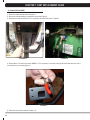
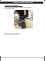
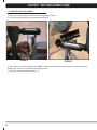
1
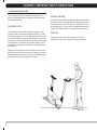
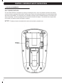
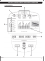
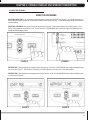
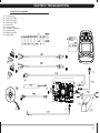
It All StArtS wIth A VISIon
It All StArtS wIth A VISIon
FItneSS™
U70 bike
SeRViCe MANUAl
TAble of CoNTeNTS
CHAPTeR 1: SeRiAl NUMbeR loCATioN ................................................................... 1
CHAPTeR 2: iMPoRTANT SAfeTy iNSTRUCTioNS
2.1
2.2
2.3
Before Getting Started .............................................................................................. 2
read and Save these Instructions ........................................................................... 3
electrical requirements ............................................................................................ 4
CHAPTeR 3: PReVeNTATiVe MAiNTeNANCe
3.1
3.2
3.3
recommended Cleaning tips ................................................................................... 5
Check for Damaged Parts ......................................................................................... 5
Care and Maintenance Instructions .......................................................................... 6
CHAPTeR 4: CoNSole oVeRlAy AND WoRkoUT DeSCRiPTioN
4.1
4.2
4.3
Console Description .................................................................................................. 7
workout overview ...................................................................................................... 10
Using the Programs ................................................................................................... 11
CHAPTeR 5: eNgiNeeRiNg MoDe
5.1
engineering Mode ..................................................................................................... 12
CHAPTeR 6: TRoUbleSHooTiNg
6.1
6.2
6.3
6.4
6.5
6.6
electrical Diagram .....................................................................................................
Console Power Issues ...............................................................................................
no or high resistance ...............................................................................................
no rPM Displayed .....................................................................................................
noise Issues...............................................................................................................
heart rate Issues ......................................................................................................
14
18
19
20
21
22
CHAPTeR 7: PART RePlACeMeNT gUiDe
7.1
7.2
7.3
7.4
7.5
7.6
7.7
7.8
7.9
7.10
7.11
7.12
7.13
7.14
Console Back replacement ....................................................................................... 23
Console replacement ................................................................................................ 24
heart rate handlebar replacement ......................................................................... 25
heart rate Grips replacement ................................................................................. 26
Console Mast replacement ....................................................................................... 27
Seat Post replacement ............................................................................................. 28
Pedal replacement .................................................................................................... 29
Side Cover removal .................................................................................................. 30
lower Control Board replacement ........................................................................... 32
Drive Belt replacement ............................................................................................. 33
Generator Belt replacement...................................................................................... 35
Generator replacement.................................................................................................. 38
Drive Axle Set replacement ........................................................................................... 41
testing the Bike ............................................................................................................... 42
i
TAble of CoNTeNTS
CHAPTeR 8: bike SPeCifiCATioNS AND ASSeMbly gUiDe
8.1
8.2
8.3
8.4
8.5
ii
iv
Unpacking the Bike ....................................................................................................
Assembly tools ..........................................................................................................
Assembly Instructions ...............................................................................................
Adjusting the Pedal Straps and Seat .........................................................................
leveling the Bike ........................................................................................................
43
44
45
50
51
CHAPTeR 1: SeRiAl NUMbeR loCATioN
1.1 SeRiAl NUMbeR loCATioN
1
CHAPTeR 2: iMPoRTANT SAfeTy iNSTRUCTioNS
2.1 befoRe geTTiNg STARTeD
the Vision Fitness U70 Bike is intended for commercial use. to
ensure your safety and protect the equipment, read all instructions
before operating the bike.
ChooSInG A SIte
the site should be well lit and well ventilated. locate the Vision
Fitness U70 Bike on a structurally solid and flat surface. the bike
should have a clearance of 20" on one side and behind the unit, and
12" on the other side from the wall or other equipment. this zone is
to allow easy access to the bike and gives the user an easy exit path
from the machine. If the site has a heavy plush carpet, to protect
the carpeting and machinery, you should place a rigid plastic base
under the unit.
Please do not place the Vision Fitness U70 Bike in an area of high
humidity, such as the vicinity of a steam room, indoor pool, or sauna.
exposure to intensive water vapor or chlorine could adversely affect
the electronics, as well as other parts of the machine.
2
MoVInG the BIKe
Your Vision Fitness U70 bike has transport wheels included for ease
of mobility. to move your Upright Bike, firmly grasp the rear of the
frame assembly, or the rear of the seat rail. Carefully lift and roll on
the transport wheels. You can also firmly grasp the handlebars and
carefully tip the bike towards you and roll on the transport wheels.
CAUtIon:
Vision Fitness bikes are well built and heavy, use care and
additional help if necessary. this bike can weigh up to 160 lbs.
CHAPTeR 2: iMPoRTANT SAfeTy iNSTRUCTioNS
2.2 ReAD AND SAVe THeSe iNSTRUCTioNS
to ensure your safety and protect the equipment, read all
instructions before operating the Vision Fitness U70 Bike.
to ensure proper use of the Vision Fitness U70 Bike, make sure
that all users read this manual. remind the users that before
undertaking any fitness program, they should obtain complete
physical examinations from their physicians. If, at any time while
exercising, the user experiences dizziness, pain, or shortness of
breath, nausea or feels faint, he or she must stop immediately.
CAUTioN! if you experience chest pains, nausea, dizziness,
or shortness of breath, stop exercising immediately and consult your physician before continuing.
CAUTioN! Any changes or modifications to this equipment
could void the product warranty.
* This bike is only to be used for its intended purpose described
in this manual. Do not use attachments that have not been recommended by Vision fitness.
* Never drop or insert objects into any opening. keep hands away
from moving parts. if the item cannot be reached, contact a Vision
fitness authorized dealer for assistance.
* Never operate the unit if it is damaged, not working properly, when
it has been dropped, or has been dropped in water.
* keep hands and feet clear at all times from moving parts to avoid
injury.
* Do not use this product outdoors, near swimming pools or in areas
of high humidity.
* Do not operate where aerosol (spray) products are being used or
when oxygen is being administered.
* Do not use this product in bare feet. Do not wear shoes with heels,
leather soles, cleats, or spikes while exercising.
* Do not remove the side covers. Service should only be done by an
authorized service technician.
* Close supervision is necessary when used near children, invalids,
or disabled people.
* When the bike is in use, young children and pets should be kept at
least 3 meters / 10 feet away.
* Assemble and operate the bike on a solid, level surface.
* Never face backward while using the Vision fitness U70 bike.
* Use the stationary handlebars when mounting or dismounting the
bike.
* Do not wear clothing that might catch on any moving parts of this
bike.
3
CHAPTeR 2: iMPoRTANT SAfeTy iNSTRUCTioNS
2.3 eleCTRiCAl ReqUiReMeNTS
SelF PowereD FeAtUreS:
the Vision Fitness U70 Bike is a self-powered unit, requiring no external power source. when a user pedals at a speed above 20 revolutions
per minute, the power is generated to allow the bike to function properly. Because of this self-generating feature, the console feedback will fade
away when you cease pedaling. the console does use a 9 volt battery as a backup to save your feedback information for 30 seconds from the
time you stop pedaling. If you resume pedaling within the 30 seconds, the information will reappear. If the information does not appear within
the 30 seconds, your battery may need to be plugged in or replaced.
BAtterY - the battery is located on the backside of the console and is enclosed by a removable cover.
4
CHAPTeR 3: PReVeNTATiVe MAiNTeNANCe
3.1 ReCoMMeNDeD CleANiNg TiPS
Preventative maintenance and daily cleaning will prolong the life and look
of your Vision Fitness U70 Bike
Please read and follow these tips.
• P
ositiontheequipmentawayfromdirectsunlight.TheintenseUVlight
can cause discoloration on plastics.
• L
ocateyourequipmentinanareawithcooltemperaturesandlow
humidity.
• Cleanwithasoft100%cottoncloth.
• C
leanwithsoapandwaterorothernon-ammoniabasedallpurpose
cleaners.
3.2 CHeCk foR DAMAgeD PARTS
Do NoT use any equipment that is damaged or has worn or
broken parts. Use only replacement parts supplied by Vision
Fitness.
MAiNTAiN lAbelS AND NAMePlATeS. Do not remove labels
for any reason. they contain important information. If unreadable
or missing, contact Vision Fitness for a replacement at 800-3354348 or www.visionfitness.com.
MAiNTAiN All eqUiPMeNT. Preventative maintenance is the
key to smoothly operating equipment. equipment needs to be
inspected at regular intervals. Defective components must be
kept out of use until they are repaired. ensure that any person(s)
making adjustments or performing maintenance or repair of any
kind is qualified to do so.
• W
ipepedals,console,heartrategrips,andthehandlebarcleanafter
each use.
• D
onotpourliquidsdirectlyontoyourequipment.Thiscancausedamage to the equipment and in some cases electrocution.
• Adjustlevelingfeetwhenequipmentwobblesorrocks.
• Maintainacleanareaaroundtheequipment,freefromdustanddirt.
5
CHAPTeR 3: PReVeNTATiVe MAiNTeNANCe
3.3 CARe AND MAiNTeNANCe iNSTRUCTioNS
In order to maximize life span, and minimize down time, all Vision
Fitness equipment requires regular cleaning, and maintenance items
performed on a scheduled basis. this section contains detailed
instructions on how to perform these items and the frequency of
which they should be done. Some basic tools and supplies will be
necessary to perform these tasks which include (but may not be
limited to):
* Metric Allen wrenches
* #2 Phillips head screwdriver
* Adjustable wrench
* lint free cleaning cloths
* teflon based spray lubricant such as "Super lube" or other Vision
Fitness approved products.
* Mild water soluble detergent such as "Simple Green" or other
Vision Fitness approved products
* Vacuum cleaner with an extendable hose and crevasse tool
attachment.
qUARTeRly MAiNTeNANCe iTeMS
1) Inspect the console mounting bolts for tightness, tighten if
necessary.
2) Inspect the console, handrails, and handlebar for damage.
3) remove the side covers and inspect the grooves on the belts
and pulleys for dust or dirt. Clean if necessary (Figures A-C).
DAily MAiNTeNANCe iTeMS
1) look and listen for loose fasteners, unusual noises, and any
other indications that the equipment may be in need of service.
2) Clean the bike before and after each use, including:
a. Use a damp, soft cloth with water or mild liquid detergent to
clean all exposed surfaces. Do not use ammonia, chlorine, or any
acid based cleaners.
b. Keep the console display free of fingerprints and salt build
up caused by sweat.
c. Frequently vacuum the floor beneath the unit to prevent the
accumulation of dust and dirt which can affect the smooth operation
of the unit.
figURe A
figURe b
MoNTHly MAiNTeNANCe iTeMS
1) Inspect the console, seat, pedals, and shrouds for damage.
2) tighten the pedals onto their respective cranks using a 15 mm
wrench.
3) Adjust leveling feet if equipment rocks or wobbles.
4) Inspect the grooves on the pedals for dust or dirt. Clean if
necessary.
6
figURe C
CHAPTeR 4: CoNSole oVeRlAy AND WoRkoUT DeSCRiPTioN
4.1 CoNSole DeSCRiPTioN
7
CHAPTeR 4: CoNSole oVeRlAy AND WoRkoUT DeSCRiPTioN
4.1 CoNSole DeSCRiPTioN - CoNTiNUeD
CoNSole DiSPlAy DeSCRiPTioNS
A. START / HolD To ReSeT - Press the StArt key to begin a Manual workout immediately without having to set individual information.
when the program begins, you have the ability to adjust resistance levels with the UP or Down Arrow keys. Feedback information will be
calculated using the default settings.
PAUSe - If you need to pause your program during a workout, pressing the StArt key will pause your program for 30 seconds. Pressing
StArt again will return you to your workout.
ReSeT - If you need to reset the console during your workout, you can do so by holding down the StArt key for 3 seconds or until the
display resets.
b. eNTeR - this key is used after entering each piece of information in setup such as age, weight, or level.
C. UP / DoWN ARRoWS - these keys are used to change values in setup mode prior to your workout. During your workout, they are used to
change workout levels. In hrt programs, they are used to change your target heart rate.
D. PRogRAM bUTToNS - these keys provide quick access to your favorite workouts. Press the ProGrAM keys repeatedly or use the UP
or Down Arrow keys to select one of the multiple workouts.
e. CHANge DiSPlAy / HolD To SCAN - Press this key to change the display information. Press and hold the key to scan automatically
between the two display options.
f. PRofile DiSPlAy - this window provides a dot matrix profile of the workout segments you are about to complete, as well as those you
have already completed, and level of resistance for each segment.
g. feeDbACk WiNDoWS - these windows provide step-by-step instructions in the setup mode, instructions, feedback, and motivational
messages during your workout.
SPeeD - the pedaling speed in miles or kilometers per hour.
DiSTANCe - the total distance traveled in miles or kilometers since the start of your workout.
WATTS - A measurement of workload. one watt is equal to six kilogram meters per minute.
MeTS - A measurement of oxygen consumption. one Met equals the approximate amount of oxygen consumed per minute by a person at
rest.
HeART RATe / HRT feeDbACk WiNDoW - this window provides feedback on your current heart rate and the percent of your predicted
maximum heart rate. It also includes your target heart rate when using one of the hrt programs.
NoTe - At the end of your workout, the totals will be displayed as an average of your total workout time. the only exceptions are distance
and calories which are program totals.
H. MeSSAge WiNDoW - this window provides step-by-step instructions in the setup mode, instructions, feedback and motivational messages
during your workout.
TiMe - the time elapsed or the time remaining in your workout.
RPM - the pedal rate or revolutions per minute (rPM).
CAloRieS - An estimate of calories burned since the beginning of the workout.
ReSiSTANCe - the current resistance level you are in.
8
CHAPTeR 4: CoNSole oVeRlAy AND WoRkoUT DeSCRiPTioN
4.1 CoNSole DeSCRiPTioN - CoNTiNUeD
CARDio PoRT
A cardio port is located on the back of the console that is compatible to entertainment protocol such as Cardio theater. the bottom port is the
active port to use for this function.
9
CHAPTeR 4: CoNSole oVeRlAy AND WoRkoUT DeSCRiPTioN
4.2 WoRkoUT oVeRVieW
WoRkoUT oVeRVieW
ClASSiCS:
MANUAL - Manual is a user controlled program in which the resistance remains as set level unless you decide to change it.
INTERVAL - Interval is an efficient workout that strengthens your cardiovascular system by alternating work intervals and recovery intervals. Be
sure to challenge yourself with intense work intervals.
FAT BURN - Fat Burn is a program designed to target your stored body fat. this program is generally used at a slightly lower resistance level
but runs for longer durations than other programs.
RANDOM - random is a workout that will give you a different workout every time you workout. the resistance levels will change randomly,
providing a challenging workout.
HRT PRogRAMS:
TARGET HRT - target hrt allows you to set your target heart rate. the machine will automatically change resistance levels to keep you at your
preset heart rate target. the user must grasp the hand pulse sensors or wear a telemetric heart rate chest strap during use.
HRT WEIGHT LOSS - hrt weight loss is a lower intensity workout that will help your body burn a higher percentage of calories from your
body's fat reserves. the user must grasp the hand pulse sensors or wear a telemetric heart rate chest strap during use. the program will
automaticallyadjustresistancetokeepyouat65%ofyourpredictedmaximumheartrate.
HRT INTERVAL -HRTIntervalalternatedbetweeneffortintervalsof80%and70%ofyourpredictedmaximumheartrate.Thisprogramis
designed to increase your cardiovascular fitness capacity. the user must grasp the hand pulse sensors or wear a telemetric heart rate chest strap
during use.
HRT HILL -HRTHillincreasesyourintensitylevelfrom65%to70%to75%to80%ofyourpredictedmaximumheartratetopromote
cardiovascular strength and endurance.
TRAilS:
TRAIL 10K - trail 10K is a distance based program that ends after you complete the 10K. See if you can beat your previous time!
TRAIL 15K - trail 15K is a distance based program that ends after you complete the 15K.
TRAIL 20K - trail 20K is a distance based program that ends after you complete the 20K.
WATTS PRogRAMS:
CONSTANT WATTS - Constant watts allows you to set your target wAtt output (energy output). the resistance will change automatically to
keep you at your target watts.
INTERVAL WATTS - Interval watts allows you to choose a high watts value and a low watts value. the interval program will switch between
high and low watts values, making for a very intense and effective workout.
HILL WATTS - hill watts lets you choose four watt levels. each watt level will change at 1 minute intervals and repeat until your preset workout
time is over. Perfect for a challenging workout.
SPRiNT 8 - Sprint 8 is an anaerobically based interval program. It is effective in recruiting fast twitch muscle fibers and improving athletic
performance.
fiTNeSS TeST - Fitness test is a heart rate based fitness test. the test lasts 5 minutes and is based on your V02 level and maximum heart
rate achieved to provide an accurate fitness level. this is a great program to track your increase in fitness levels. the user must grasp the hand
pulse sensors or wear a telemetric heart rate chest strap during use.
CUSToM PRogRAMS - Custom 1-5 allows the user to preset up to 5 workout profiles. You have the ability to save or change the workouts
whenever you wish. During initial setup, the program will function as a Manual program. Change your resistance levels as you want. At the end of
the workout, the console will ask if you would like to save your workout. Press and hold enter to save the workout you just completed.
10
CHAPTeR 4: CoNSole oVeRlAy AND WoRkoUT DeSCRiPTioN
4.3 USiNg THe PRogRAMS
USiNg THe PRogRAMS
SeleCTiNg qUiCk START - the easiest way to begin exercising is to simply press the StArt key (Figure A). You will begin exercising in a
Manual resistance program in which you can change the resistance levels to meet your goals. Current default settings will be used to determine
exercise feedback.
SeleCTiNg A PRogRAM - each program has its own program button (Figure B). Some programs buttons have multiple programs. Press
the key of the program that you would like to use. You can use the UP or Down Arrow keys or press the program key repeatedly to scroll
through the different program options.
figURe A
figURe b
eNTeRiNg Age - when prompted by the message center to enter your age, use the UP or Down Arrow keys to adjust the displayed age to
thecorrectvalue(FigureC).ThisinformationisnecessaryfortheHRTprogramsandwillaffectyour%HeartRatefeedback.
eNTeRiNg TiMe - when prompted by the message center to enter your time, use the UP or Down Arrow keys to adjust the displayed time
to a desired value (FIgure D).
figURe C
figURe D
11
CHAPTeR 4: CoNSole oVeRlAy AND WoRkoUT DeSCRiPTioN
4.3 USiNg THe PRogRAMS - CoNTiNUeD
USiNg THe PRogRAMS - Continued
eNTeRiNg ReSiSTANCe - when prompted by the message center to enter level, use the UP and Down Arrow keys to adjust the displayed
resistance level (Figure e). there are 20 levels of resistance to choose from in each program. the maximum resistance level varies by
program.
eNTeRiNg WeigHT - when prompted by the message center to enter weight, use the UP and Down Arrow keys to adjust the displayed
weight to equal your current body weight (Figure F). this information is necessary to give accurate exercise feedback for calorie and Met
calculations.
eNTeRiNg WATTS - the watts program will ask you to set the desired watt level instead of resistance levels. the watts level will range from
40 to 250 in increments of five.
eNTeRiNg TARgeT HRT - the hrt programs will set your target heart rate in the place of resistance level. the console will display your
target heart rate and give you the opportunity to adjust this value if you wish.
figURe e
figURe f
SPRiNT 8 - the Sprint 8 program is an aerobic interval program designed to build muscle, improve speed, and naturally increase the release of
human Growth hormone (hGh) in your body. Producing hGh through exercise and a proper diet has been shown as an effective way to burn
fat and build lean muscle mass according to Phil Campbell, author of ready, Set, Go! Synergy Fitness. Please go to Mr. Campbell's website,
www.readysetgofitness.com for more details about this radical new approach to fitness.
the Sprint 8 program features intense sprint intervals followed by recovery intervals. the program includes the following phases:
1) wArM UP should gradually increase your heart rate and increase respiration and blood flow to working muscles. the warm up is controlled
by the user to meet your specific needs.
2) InterVAl trAInInG starts immediately after the warm up with a 30 second sprint interval. Seven recovery intervals of one minute and
30 seconds will alternate with the eight 30 second sprint intervals. the message display will prompt you to increase your pedal rate during
the sprint interval and decrease pedal rate during the recovery interval. A difference of 30 to 50 rPM between interval and recovery interval is
recommended.
3) Cool Down helps return your body's systems to resting levels. less demand is placed on your heart during recovery if an appropriate
cool down is used following the exercise.
Due to the fact that Sprint 8 is a specialized program, total workout time is not displayed during the program. the interval time is displayed in
the time window instead. It takes only 20 minutes to complete the Sprint 8 workout.
12
CHAPTeR 5: eNgiNeeRiNg MoDe
5.1 eNgiNeeRiNg MoDe
the engineering Mode allows the club owner to customize the bike for the club.
1) to enter engineering Mode, press and hold down the UP and Down Arrow keys at the same time for 3-5 seconds.
2) the console will beep 3 times and enter into the engineering Mode menu.
3) to scroll through the list of options in engineering Mode, use the UP and Down Arrow keys. each of the custom settings will show on
the display.
4) to select a custom setting, press the enter key when the desired setting is shown.
5) to change the value of the setting, use the UP and Down Arrow keys.
6) to confirm and save the value of the setting, press and hold enter for 3 seconds.
7) to back out of a setting or to exit the engineering Mode, press and hold StArt for 3 seconds.
CUSToM SeTTiNgS
DefAUlT
MiNiMUM
MAxiMUM
DeSCrIPtIon
MAx tIMe
99
5
99
Maximum workout duration.
USer tIMe
60
5
99 (lIMIteD
to MAx tIMe
SettInG)
Default start time in all programs.
DeFAUlt AGe
40
10
100
Default age used for all programs.
DeFAUlt weIGht
150
80
400
Default weight used for all programs.
DeFAUlt leVel
1
1
20
Default level used for all programs.
DeFAUlt GenDer
MAle
FeMAle
MAle
Default gender used for all programs.
UnIt
MIle
KM
UnIt
Sets the unit to miles or kilometers.
MAChIne
BIKe
BIKe
ellIPtICAl
Sets the machine to bike or elliptical
mode.
ACCUMUlAteD tIMe
-
-
-
Shows the total time on the bike in
hours.
ACCUMUlAteD DIStAnCe
-
-
-
Shows the total distance on the bike
in miles or kilometers.
DISPlAY teSt
-
-
-
Used by service technicians to test
the leD displays.
MAChIne teSt
-
-
-
Used by service technicians to test
mechanical and CSafe functions.
KeYPAD teSt
-
-
-
test to ensure that all buttons are
functioning properly.
VerSIon
-
-
-
Displays current software version.
lAnGUAGe
-
-
-
Sets the language that the prompts
use in the instruction center.
13
CHAPTeR 6: TRoUbleSHooTiNg
6.1 eleCTRiCAl DiAgRAMS
eleCTRiCAl bloCk DiAgRAM
14
CHAPTeR 6: TRoUbleSHooTiNg
6.1 eleCTRiCAl DiAgRAMS
A1 = Console Cable
A2 = hand Pulse Cable
A3 = hand Pulse Cable
A4 = hand Pulse Cable
G1 = Power wire
G2 = Power resistor
G3 = Generator / Generator
G4 = Console Cable
G5 = Battery light wire
G6 = Battery wire
15
CHAPTeR 6: TRoUbleSHooTiNg
6.1 eleCTRiCAl DiAgRAMS
P21 - CoNSole CAble
V
V
rDA
SDB
SDA
SDB
GnD
GnD
16
CHAPTeR 6: TRoUbleSHooTiNg
6.1 eleCTRiCAl DiAgRAMS
P04 - PUlSe SeNSoR WiRe
17
CHAPTeR 6: TRoUbleSHooTiNg
6.2 TRoUbleSHooTiNg - CoNSole PoWeR iSSUeS
No DiSPlAy oN THe CoNSole oR THe DiSPlAy iS DiM
PoSSible CAUSeS:
1)
2)
3)
4)
the console is damaged or the console cable is not connected properly.
Poor connection to the terminals on the lower board.
the lower board is damaged.
the Generator is damaged.
SolUTioN
1) Check the console cable connections at the console and lower board.
2) Unplug the console cable at the console. Use a multi-meter to check if the voltage between the 1 (VCC) and 8 (Ground) pins of the console
cable is greater than 12 VDC (Figure A).
a. If the voltage is greater than 12 VDC, replace the console.
3) open the side covers and check the lower board leDs. If the +12V leD is not lit, replace the battery.
4) Unplug the generator cable from the lower board and check to see if the voltage is variable (See Section 6.2 for how to check the power).
a. If the voltage is variable, replace the lower board.
b. If the voltage is not variable, replace the generator.
V
V
rDA
SDB
SDA
SDB
GnD
GnD
figURe A
18
CHAPTeR 6: TRoUbleSHooTiNg
6.3 TRoUbleSHooTiNg - No oR HigH ReSiSTANCe
No ReSiSTANCe CHANge oR AlWAyS HigH ReSiSTANCe
PoSSible CAUSeS:
1)
2)
3)
4)
the
the
the
the
console is damaged or the console cable is not connected properly.
console cable is damaged.
generator is damaged.
lower board is damaged.
SolUTioN:
1) Check the console cable connections at the console and lower board.
2) Unplug the generator cable from the lower board and pedal the machine. Use a multi-meter to check the VAC (AC voltage) readout from the
generator cable (Figures A & B).
a. the VAC should vary depending on how fast the unit is pedaled.
b. If the VAC is not variable, replace the generator.
c. If the voltage is variable, replace the lower board.
d. If the issue is not resolved by the generator or lower board, replace the console.
e. If the issue is still not resolved, replace the console cable.
figURe A
figURe b
19
CHAPTeR 6: TRoUbleSHooTiNg
6.4 TRoUbleSHooTiNg - No RPM DiSPlAyeD
No RPM iS DiSPlAyeD DURiNg exeRCiSe
PoSSible CAUSeS:
1) the generator is damaged or the console cable is not connected properly.
2) the console is damaged.
3) the lower board is damaged.
SolUTioN:
1) open the side covers and check the lower board leDs. the rPM leD should have light.
a. If the rPM leD is not lit, check the generator for variable power (see Section 6.2 for how to check the power). replace the generator
if variable power is not present.
2) If the rPM leD is lit, but the console does not show the rPM, replace the console cable.
a If the console cable does not resolve the issue, replace the console.
b. If the console cable and console do not resolve the issue, replace the lower board.
20
CHAPTeR 6: TRoUbleSHooTiNg
6.5 TRoUbleSHooTiNg - NoiSe iSSUeS
kNoCkiNg oR CReAkiNg NoiSeS
PoSSible CAUSeS:
1)
2)
3)
4)
the pedal is connected to the crank arm too loosely.
Belt tension is too loose, or the belt is dirty.
the crank is damaged.
the drive axle assembly is damaged.
SolUTioN:
1) open the side covers and clean and tighten the belts.
2) tighten the connections between the pedal and crank arm.
3) replace the crank.
4) replace the drive axle assembly.
21
CHAPTeR 6: TRoUbleSHooTiNg
6.6 TRoUbleSHooTiNg - HeART RATe iSSUeS
HeART RATe DoeS NoT WoRk
PoSSible CAUSeS:
1)
2)
3)
4)
5)
not good contact between the user and hr grips or hr strap.
the hr strap is at a low battery status.
the hr strap is damaged.
the hr grips are damaged.
the hr board in the console is damaged.
SolUTioN:
1) re-center the hr strap on user's chest as shown in Figure A.
2) replace the battery in the hr Strap.
3) wet the user's hand, then reestablish contact with the hr grip.
4) replace the hr strap.
5) replace the hr grips.
6) replace the console.
figURe A
22
CHAPTeR 7: PART RePlACeMeNT gUiDe
7.1 CoNSole bACk RePlACeMeNT
1) remove the 4 screws holding the back of the console to the console (Figure A).
2) remove the console back (Figure B).
figURe A
figURe b
3) reverse Steps 1-2 to install a new console back.
23
CHAPTeR 7: PART RePlACeMeNT gUiDe
7.2 CoNSole RePlACeMeNT
1) remove the console back as outlined in Section 7.1.
2) remove the 4 screws holding the console to the console mast (Figure A).
3) Disconnect the 3 wire connections (5 if a tV is present) to the console and remove it (Figure B).
figURe b
figURe A
4) reverse Steps 1-3 to install a new console. NOTE: If a tV is not present, 2 of the wires coming up the console mast will not be used, a
coax cable and a 4 pin connector)(Figure C).
figURe C
5) test the bike for function as outlined in Section 7.14.
24
CHAPTeR 7: PART RePlACeMeNT gUiDe
7.3 HeART RATe HANDlebAR RePlACeMeNT
1) remove the 2 bolts on each side holding the heart rate handlebars to the console mast (Figure A).
2) remove the heart rate handlebars.
figURe A
3) reverse Steps 1-2 to install a new heart rate handlebar.
4) test the bike for function as outlined in Section 7.14.
25
CHAPTeR 7: PART RePlACeMeNT gUiDe
7.4 HeART RATe gRiPS RePlACeMeNT
1) remove the 2 screws holding the 2 sides of the heart rate grip together (Figure A).
2) remove the heart rate grip from the heart rate handlebars (Figure B).
figURe A
figURe b
3) reverse Steps 1-2 to install new heart rate grips. NOTE: the white wire goes to the bottom heart rate plate, the red wire goes to the top
heart rate plate. Also be sure to re-install both heart rate grip end caps.
4) test the bike for function as outlined in Section 7.14.
26
CHAPTeR 7: PART RePlACeMeNT gUiDe
7.5 CoNSole MAST RePlACeMeNT
1)
2)
3)
4)
5)
remove the console back as outlined in Section 7.1.
remove the console as outlined in Section 7.2.
remove the heart rate handlebars as outlined in Section 7.3.
lift up the console mast boot and remove the 3 bolts on each side holding the console mast to the frame (Figure A).
Pull the console mast up and off the unit while simultaneously pulling the console cable wires out the bottom of the console mast (Figure B).
figURe A
figURe b
6) reverse Steps 1-5 to install a new console mast.
7) test the bike for function as outlined in Section 7.14.
27
CHAPTeR 7: PART RePlACeMeNT gUiDe
7.6 SeAT PoST RePlACeMeNT
1) turn the pin counter-clockwise with a 17mm wrench (Figure A).
2) remove the seat pin (Figure B).
figURe A
figURe b
3) Pull up on the seat post and pull it off the unit (Figure C).
figURe C
4) reverse Steps 1-3 to install a new post.
28
CHAPTeR 7: PART RePlACeMeNT gUiDe
7.7 PeDAl RePlACeMeNT
1) Use a 15mm pedal wrench to turn the pedal bolt (counter-clockwise for the right pedal, clockwise for the left pedal)(Figure A).
2) remove the pedal (Figure B).
figURe A
figURe b
3) reverse Steps 1-2 to install a new pedal.
29
CHAPTeR 7: PART RePlACeMeNT gUiDe
7.8 SiDe CoVeR ReMoVAl
1) Use a flat screwdriver to turn the cover over the crank arm counter-clockwise and remove it (Figures A & B).
figURe A
figURe b
2) remove the 14mm nut holding the crank to the drive axle (Figures C & D).
figURe C
30
figURe D
CHAPTeR 7: PART RePlACeMeNT gUiDe
7.8 SiDe CoVeR ReMoVAl - CoNTiNUeD
3) Use a 22mm crank puller (Vision Fitness part # ZMS2000030) to remove the crank (Figures e & F).
figURe e
figURe f
4) remove the seat adjustment pin and seat post as outlined in Section 7.6. Also remove the seat post boot.
5) remove the 10 screws holding each side cover to the frame and remove the side covers (Figures G & h).
figURe g
figURe H
31
CHAPTeR 7: PART RePlACeMeNT gUiDe
7.9 loWeR CoNTRol boARD RePlACeMeNT
1) remove both side covers as outlined in Section 7.8.
2) remove the 2 screws holding the lower control board to the frame (Figure A).
3) Disconnect the 3 wire connections at the lower control board and remove the board (Figure B).
figURe b
figURe A
4) reverse Steps 1-3 to install a new lower control board. NOTE: Be sure to re-attach the 3 wire connections removed in Step 3 (Figure C).
5) test the bike for function as outlined in Section 7.14.
figURe C
32
CHAPTeR 7: PART RePlACeMeNT gUiDe
7.10 DRiVe belT RePlACeMeNT
1) remove both of the side covers as outlined in Section 7.8.
2) remove the bolt holding the idler tension spring to the frame (Figure A). once this bolt is removed, the idler can be pivoted to remove the
tension from the drive belt (Figure B).
figURe A
figURe b
3) remove the 3 bolts on each side holding the secondary pulley assembly to the frame (Figure C).
4) loosen the 15mm nut on each side holding the generator to the frame (Figure D).
figURe C
figURe D
33
CHAPTeR 7: PART RePlACeMeNT gUiDe
7.10 DRiVe belT RePlACeMeNT - CoNTiNUeD
5) loosen the 11mm eye hook nut on each side holding the generator from sliding in the frame (Figure e).
6) Slide the generator towards the rear of the unit (Figure F).
figURe e
figURe f
7) when the generator is slid towards the back of the frame, the tension on the generator belt is reduced so that the belt can be removed from
around the pulley portion of the secondary pulley assembly (Figure G).
8) once the generator belt is removed from around the pulley, the secondary pulley assembly can be slid towards the rear of the unit so that
the drive belt can be removed (Figure h).
figURe g
9) reverse Steps 1-8 to install a new drive belt.
10) test the bike for function as outlined in Section 7.14.
34
figURe H
CHAPTeR 7: PART RePlACeMeNT gUiDe
7.11 geNeRAToR belT RePlACeMeNT
1) remove both of the side covers as outlined in Section 7.8.
2) remove the bolt holding the idler tension spring to the frame (Figure A). once this bolt is removed, the idler can be pivoted to remove the
tension from the drive belt (Figure B).
figURe A
figURe b
3) remove the 3 bolts on each side holding the secondary pulley assembly to the frame (Figure C).
4) loosen the 15mm nut on each side holding the generator to the frame (Figure D).
figURe C
figURe D
35
CHAPTeR 7: PART RePlACeMeNT gUiDe
7.11 geNeRAToR belT RePlACeMeNT - CoNTiNUeD
5) loosen the 11mm eye hook nut on each side holding the generator from sliding in the frame (Figure e).
6) remove the bolt preventing the generator disc from spinning (Figure G).
figURe e
figURe f
7) Slide the generator towards the rear of the unit (Figure G).
8) when the generator is slid towards the rear of the unit, the tension on the generator belt is reduced so that the belt can be removed from
around the pulley portion of the secondary pulley assembly (Figure h).
figURe g
36
figURe H
CHAPTeR 7: PART RePlACeMeNT gUiDe
7.11 geNeRAToR belT RePlACeMeNT - CoNTiNUeD
9) once the generator belt is removed from around the pulley on the secondary pulley assembly, the generator can be pulled towards the front
of the unit so that the generator belt can be removed from around the generator pulley (Figure I).
10) once the generator belt is removed from around the generator pulley, the secondary pulley assembly can be slid toward the rear of the unit
so that the generator belt can be completely removed from the secondary pulley assembly (Figure J).
figURe i
figURe J
11) reverse Steps 1-10 to install a new generator belt. NOTE: Be sure to tension the new generator belt so that it can be twisted a maximum
of 45 degrees (Figure K).
12) test the bike for function as outlined in Section 7.14.
figURe k
37
CHAPTeR 7: PART RePlACeMeNT gUiDe
7.12 geNeRAToR RePlACeMeNT
1) remove both of the side covers as outlined in Section 7.8.
2) remove the bolt holding the idler tension spring to the frame (Figure A). once this bolt is removed, the idler can be pivoted to remove the
tension from the drive belt (Figure B).
figURe A
figURe b
3) remove the 3 bolts on each side holding the secondary pulley assembly to the frame (Figure C).
4) loosen the 15mm nut on each side holding the generator to the frame (Figure D).
figURe C
38
figURe D
CHAPTeR 7: PART RePlACeMeNT gUiDe
7.12 geNeRAToR RePlACeMeNT - CoNTiNUeD
5) loosen the 11mm eye hook nut on each side holding the generator from sliding in the frame (Figure e).
6) remove the bolt preventing the generator disc from spinning (Figure F).
figURe e
figURe f
7) Slide the generator towards the rear of the unit (Figure G).
8) when the generator is slid towards the rear of the unit, the tension on the generator belt is reduced so that the belt can be removed from
around the pulley portion of the secondary pulley assembly (Figure h).
figURe g
figURe H
39
CHAPTeR 7: PART RePlACeMeNT gUiDe
7.12 geNeRAToR RePlACeMeNT - CoNTiNUeD
9) once the generator belt is removed from around the pulley on the secondary pulley assembly, the generator can be pulled towards the front
of the unit so that the generator belt can be removed from around the generator pulley (Figure I).
10) Unplug the generator wire and cut any wire ties holding the generator wire to the frame (Figure J).
figURe i
figURe J
11) once the generator belt is removed from the generator pulley and the generator wire is unplugged, the generator can be removed from the
front end of the frame (Figure K).
12) reverse Steps 1-11 to install a new generator. NOTE: Be sure to tension the new generator belt so that it can be twisted a maximum of
45 degrees (Figure l).
13) test the bike for function as outlined in Section 7.14.
figURe k
40
figURe l
CHAPTeR 7: PART RePlACeMeNT gUiDe
7.13 DRiVe Axle SeT RePlACeMeNT
1) remove both of the side covers as outlined in Section 7.8.
2) remove the drive belt as outlined in Section 7.10.
3) remove the snap ring holding the drive axle set into the frame (Figure A).
4) Use a hammer or a mallet on the left side of the frame to remove the drive axle set from the right side of the frame (Figure B). NOTE: the
drive axle bearings will be damaged during the removal process. new bearings are included with the new drive axle set.
figURe A
figURe b
5) reverse Steps 1-4 to install a new drive axle.
6) test the bike for function as outlined in Section 7.14.
41
CHAPTeR 7: PART RePlACeMeNT gUiDe
7.14 TeSTiNg THe bike
onCe the UnIt or rePlACeMent PArt IS FUllY InStAlleD AnD ASSeMBleD AnD
ProPerlY PlACeD on the Floor, USe the FollowInG InStrUCtIonS to teSt
the MAChIne:
1) without hitting start or entering any program modes, sit on the bike and hold the handlebars while pedaling to simulate exercising. while
moving, listen for any odd noises or squeaks.
2) After stopping movement, press the StArt button and begin pedaling.
3) Grasp the hand grips to check for proper heart rate response.
4) Press the level up and down buttons on the console to make sure resistance is fully functional.
5) If everything functions properly, stop pedaling and the unit will reset to normal operation within 30 seconds.
42
CHAPTeR 8: bike SPeCifiCATioNS AND ASSeMbly gUiDe
8.1 UNPACkiNg THe bike
the Vision Fitness U70 Bike is carefully inspected before shipment, so it should arrive in good operating condition. Vision Fitness ships the bike
in the following pieces:
NOTE: If these parts are missing from the package, please contact Vision Fitness at 1-800-335-4348.
43
CHAPTeR 8: bike SPeCifiCATioNS AND ASSeMbly gUiDe
8.2 ASSeMbly ToolS
ToolS ReqUiReD foR ASSeMbly
5mm t-handled Allen wrench
44
Phillips Screwdriver
15mm Pedal wrench
CHAPTeR 8: bike SPeCifiCATioNS AND ASSeMbly gUiDe
8.3 ASSeMbly iNSTRUCTioNS
STeP 1 - oRANge bAg
1) Install the rear foot with four lock washers (M8), two inside bolts (M8 x 65l), and two outside bolts (M8 x 20l). tighten with the 5mm
t-Shaped Allen wrench.
45
CHAPTeR 8: bike SPeCifiCATioNS AND ASSeMbly gUiDe
8.3 ASSeMbly iNSTRUCTioNS - CoNTiNUeD
STeP 2 - blUe bAg
1) Slide the console mast boot onto the console mast.
2) Unfold the wire harness located in the console mast frame bracket. Connect it to the wire tie coming from the bottom of the console mast.
Pull the wire tie and wire harness up through the top of the console mast while simultaneously sliding the mast into the frame.
3) Secure the mast to the frame using six lock washers (M8), and six bolts (M8 x 15l). tighten with the 5mm t-Shaped Allen wrench. Place
the seventh bolt (M8 x 15l) in the rear of the frame bracket and tighten until snug.
4) Slide the console mast boot down and set it in place on the side cover.
5) remove the nuts (M8) from the bottom of the seat. Attach the seat to the seat post with the nuts you just removed. tighten with the 15mm
wrench.
46
CHAPTeR 8: bike SPeCifiCATioNS AND ASSeMbly gUiDe
8.3 ASSeMbly iNSTRUCTioNS - CoNTiNUeD
STeP 3 - PiNk bAg
1) Feed the heart rate wires of the handlebar through the small hole located in the front of the console mast. Pull these wires up through the
hole at the top of the console mast. Attach the handlebar to the console mast using four bolts (M8 x 20l). tighten with the 5mm t-Shaped
Allen wrench.
47
CHAPTeR 8: bike SPeCifiCATioNS AND ASSeMbly gUiDe
8.3 ASSeMbly iNSTRUCTioNS - CoNTiNUeD
STeP 4 - CoNSole
1) remove the four mounting bolts from the back of the console and four screws holding the console back cover on with the Phillips
Screwdriver. Plug in the wire harness and the two heart rate wires to the back of the console. Attach the console to the console mast with the
four bolts removed earlier in this step.
2) Plug in the 9 volt battery. re-attach the console back cover with the four screws removed previously.
3) with the Phillips Screwdriver, remove the 2 bolts located half way up the console mast. Attach the accessory tray to the console mast the two
bolts.
48
CHAPTeR 8: bike SPeCifiCATioNS AND ASSeMbly gUiDe
8.3 ASSeMbly iNSTRUCTioNS - CoNTiNUeD
fiNAl ASSeMbly
49
CHAPTeR 8: bike SPeCifiCATioNS AND ASSeMbly gUiDe
8.4 ADJUSTiNg THe PeDAl STRAPS AND SeAT
ADJUSTiNg THe PeDAl STRAPS
the straps are designed to fit your individual foot size and should be adjusted tight enough to keep your foot from slipping. the pedals include
spring loaded clips for easy adjustment. to tighten the strap, pull down the open end of the strap. to loosen the strap, push down on the top of
the clip and pull the strap up. release the clip to lock the strap in place.
ADJUSTiNg THe U70 SeAT
the U70 bike uses a simple pull pin adjustment knob to adjust the
seat height. to adjust the seat, grab hold of the seat and pull the
seat post knob out. raise or lower the seat to its desired position
and release the seat post knob. Push down on the seat to make
sure that the pin is secure in the seat rail.
to determine the proper seat position, sit on the seat and position
the ball of your foot on the center of the pedal. Your knee should
bend slightly at the furthest pedal position. You should be able to
pedal without locking your knees or shifting your weight from side
to side.
50
CHAPTeR 8: bike SPeCifiCATioNS AND ASSeMbly gUiDe
8.5 leVeliNg THe bike
STAbiliZiNg THe ViSioN fiTNeSS U70 bike
After positioning the bike in its intended location, check its stability by attempting to shake it side to side. Shaking or wobbling indicates that
your bike needs to be leveled. Determine which leveler is not resting completely on the floor. loosen the nut with one hand to allow the leveler
to rotate. rotate the left or right leveler, and repeat the adjustment as necessary until the bike is stable. lock the adjustment by tightening the
nut against the rear foot support.
51
NoTeS
52
It All StArtS wIth A
VISIon FItneSS™
Vi Si o N f i T N e S S S yS T eM S C oR P.
1610 lAn DM Ar K Dr I V e C o t tA G e G r o Ve wI 5 3 5 2 7 U S A
to ll F ree 800. 335. 4348
w w w. v i s i o n f i t n e s s . c o m
FA x 6 0 8 . 8 3 9 . 1 7 1 7
ko
ReV. 1
53