
1
53-1001766-01
30 March 2010
Fabric OS FCIP
Administrator’s Guide
Supporting Fabric OS v6.4.0
®
Copyright © 2009-2010 Brocade Communications Systems, Inc. All Rights Reserved.
Brocade, the B-wing symbol, BigIron, DCX, Fabric OS, FastIron, IronPoint, IronShield, IronView, IronWare, JetCore, NetIron,
SecureIron, ServerIron, StorageX, and TurboIron are registered trademarks, and DCFM, Extraordinary Networks, and SAN Health
are trademarks of Brocade Communications Systems, Inc., in the United States and/or in other countries. All other brands,
products, or service names are or may be trademarks or service marks of, and are used to identify, products or services of their
respective owners.
Notice: This document is for informational purposes only and does not set forth any warranty, expressed or implied, concerning
any equipment, equipment feature, or service offered or to be offered by Brocade. Brocade reserves the right to make changes to
this document at any time, without notice, and assumes no responsibility for its use. This informational document describes
features that may not be currently available. Contact a Brocade sales office for information on feature and product availability.
Export of technical data contained in this document may require an export license from the United States government.
The authors and Brocade Communications Systems, Inc. shall have no liability or responsibility to any person or entity with
respect to any loss, cost, liability, or damages arising from the information contained in this book or the computer programs that
accompany it.
The product described by this document may contain “open source” software covered by the GNU General Public License or other
open source license agreements. To find out which open source software is included in Brocade products, view the licensing
terms applicable to the open source software, and obtain a copy of the programming source code, please visit
http://www.brocade.com/support/oscd.
Brocade Communications Systems, Incorporated
Corporate and Latin American Headquarters
Brocade Communications Systems, Inc.
1745 Technology Drive
San Jose, CA 95110
Tel: 1-408-333-8000
Fax: 1-408-333-8101
E-mail: [email protected]
Asia-Pacific Headquarters
Brocade Communications Systems China HK, Ltd.
No. 1 Guanghua Road
Chao Yang District
Units 2718 and 2818
Beijing 100020, China
Tel: +8610 6588 8888
Fax: +8610 6588 9999
E-mail: [email protected]
European Headquarters
Brocade Communications Switzerland Sàrl
Centre Swissair
Tour B - 4ème étage
29, Route de l'Aéroport
Case Postale 105
CH-1215 Genève 15
Switzerland
Tel: +41 22 799 5640
Fax: +41 22 799 5641
E-mail: [email protected]
Asia-Pacific Headquarters
Brocade Communications Systems Co., Ltd. (Shenzhen WFOE)
Citic Plaza
No. 233 Tian He Road North
Unit 1308 – 13th Floor
Guangzhou, China
Tel: +8620 3891 2000
Fax: +8620 3891 2111
E-mail: [email protected]
Document History
Title
Publication number
Summary of changes
Date
Fabric OS FCIP Administrator’s Guide
53-1001349-01
New document.
July 2009
Fabric OS FCIP Administrator’s Guide
53-1001349-02
Various changes and
corrections.
October 2009
Fabric OS FCIP Administrator’s Guide
53-1001755-01
New document for Fabric OS January 2010
version 6.3.1.
Fabric OS FCIP Administrator’s Guide
53-1001766-01
New document for Fabric OS March 2010
version 6.4.0.
Fabric OS FCIP Administrator’s Guide
53-1001766-01
iii
iv
Fabric OS FCIP Administrator’s Guide
53-1001766-01
Contents
Chapter 1
FCIP overview
In this chapter . . . . . . . . . . . . . . . . . . . . . . . . . . . . . . . . . . . . . . . . . . . . 1
FCIP platforms and supported features . . . . . . . . . . . . . . . . . . . . . . . 1
FCIP concepts . . . . . . . . . . . . . . . . . . . . . . . . . . . . . . . . . . . . . . . . . . . . 3
IP WAN network considerations . . . . . . . . . . . . . . . . . . . . . . . . . . . . . . 3
Chapter 2
FCIP on the 7800 Switch and FX8-24 Blade
In this chapter . . . . . . . . . . . . . . . . . . . . . . . . . . . . . . . . . . . . . . . . . . . . 5
7800 switch hardware overview . . . . . . . . . . . . . . . . . . . . . . . . . . . . . 6
7800 switch license options . . . . . . . . . . . . . . . . . . . . . . . . . . . . . . . . 6
VE_Ports and FCIP tunnels on the 7800 switch . . . . . . . . . . . . . 7
FCIP trunking capacity on the 7800 switch . . . . . . . . . . . . . . . . . 7
FX8-24 blade hardware overview. . . . . . . . . . . . . . . . . . . . . . . . . . . . . 8
FX8-24 blade licensing options . . . . . . . . . . . . . . . . . . . . . . . . . . . . . 10
VE_Ports and FCIP tunnels on the FX8-24 blade. . . . . . . . . . . . 10
FCIP trunking capacity on the FX8-24 blade . . . . . . . . . . . . . . . 10
FCIP trunking . . . . . . . . . . . . . . . . . . . . . . . . . . . . . . . . . . . . . . . . . . . . 10
Design for redundancy and fault tolerance . . . . . . . . . . . . . . . . 11
FCIP tunnel restrictions for FCP and FICON
acceleration features. . . . . . . . . . . . . . . . . . . . . . . . . . . . . . . . . . 11
FCIP circuits . . . . . . . . . . . . . . . . . . . . . . . . . . . . . . . . . . . . . . . . . 11
FCIP circuit failover capabilities . . . . . . . . . . . . . . . . . . . . . . . . .12
Bandwidth calculation during failover . . . . . . . . . . . . . . . . . . . .13
Adaptive Rate Limiting . . . . . . . . . . . . . . . . . . . . . . . . . . . . . . . . . . . . 14
FSPF link cost calculation when ARL is used. . . . . . . . . . . . . . . 14
QoS SID/DID priorities over an FCIP trunk . . . . . . . . . . . . . . . . . . . . 15
QOS, DSCP, and VLANs . . . . . . . . . . . . . . . . . . . . . . . . . . . . . . . . . . . . 16
DSCP quality of service . . . . . . . . . . . . . . . . . . . . . . . . . . . . . . . . 16
VLANs and layer two quality of service . . . . . . . . . . . . . . . . . . . . 16
When both DSCP and L2CoS are used. . . . . . . . . . . . . . . . . . . . 16
DSCP and VLAN support on FCIP circuits. . . . . . . . . . . . . . . . . . 17
Managing the VLAN tag table . . . . . . . . . . . . . . . . . . . . . . . . . . . 19
Compression options . . . . . . . . . . . . . . . . . . . . . . . . . . . . . . . . . . . . .20
IPSec implementation over FCIP tunnels . . . . . . . . . . . . . . . . . . . . .20
Limitations in using IPSec over FCIP tunnels. . . . . . . . . . . . . . .20
IPSec for the 7800 and FX8-24 blade . . . . . . . . . . . . . . . . . . . . 21
Enabling IPSec and IKE policies . . . . . . . . . . . . . . . . . . . . . . . . . 21
Fabric OS FCIP Administrator’s Guide
53-1001766-01
v
Open Systems Tape Pipelining . . . . . . . . . . . . . . . . . . . . . . . . . . . . . .23
FCIP Fastwrite and OSTP configurations . . . . . . . . . . . . . . . . . .23
Support for IPv6 Addressing. . . . . . . . . . . . . . . . . . . . . . . . . . . . . . . . 24
IPv6 with Embedded IPv4 Addresses . . . . . . . . . . . . . . . . . . . . .25
Configuration preparation . . . . . . . . . . . . . . . . . . . . . . . . . . . . . . . . .26
Configuration steps . . . . . . . . . . . . . . . . . . . . . . . . . . . . . . . . . . . . . . .26
Setting VE_ports to persistently disabled state . . . . . . . . . . . . . 27
Configuring VEX_ports . . . . . . . . . . . . . . . . . . . . . . . . . . . . . . . . . 27
Configuring the media type for GbE ports 0 and 1
(7800 switch only) . . . . . . . . . . . . . . . . . . . . . . . . . . . . . . . . . . . . 27
Setting the GbE port operating mode (FX8-24 blade only) . . . .28
Configuring a GbE or XGE port IP address . . . . . . . . . . . . . . . . .29
Configuring an IP route . . . . . . . . . . . . . . . . . . . . . . . . . . . . . . . .30
Validating IP connectivity. . . . . . . . . . . . . . . . . . . . . . . . . . . . . . .30
Creating an FCIP tunnel. . . . . . . . . . . . . . . . . . . . . . . . . . . . . . . . 31
Creating additional FCIP circuits . . . . . . . . . . . . . . . . . . . . . . . .35
Verifying the FCIP tunnel configuration . . . . . . . . . . . . . . . . . . .35
Enabling persistently disabled ports . . . . . . . . . . . . . . . . . . . . .36
Modifying an FCIP tunnel . . . . . . . . . . . . . . . . . . . . . . . . . . . . . . . . . . 37
Modifying an FCIP circuit . . . . . . . . . . . . . . . . . . . . . . . . . . . . . . . . . . 37
Deleting an IP interface . . . . . . . . . . . . . . . . . . . . . . . . . . . . . . . . . . . 37
Deleting an IP route . . . . . . . . . . . . . . . . . . . . . . . . . . . . . . . . . . . . . .38
Deleting an FCIP tunnel . . . . . . . . . . . . . . . . . . . . . . . . . . . . . . . . . . .38
Deleting an FCIP circuit. . . . . . . . . . . . . . . . . . . . . . . . . . . . . . . . . . . .38
Virtual fabrics and the FX8-24 blade . . . . . . . . . . . . . . . . . . . . . . . . .38
Chapter 3
FCIP on the 7500 Switch and FR4-18i Blade
In this chapter . . . . . . . . . . . . . . . . . . . . . . . . . . . . . . . . . . . . . . . . . . .39
The 7500 switch and FR4-18i blade . . . . . . . . . . . . . . . . . . . . . . . . .40
7500 switch and FR4-18i blade ports . . . . . . . . . . . . . . . . . . . . 41
FCIP Design Considerations for the 7500 switch and
FR4-18i blade . . . . . . . . . . . . . . . . . . . . . . . . . . . . . . . . . . . . . . . . . . . 41
Virtual ports and FCIP tunnels . . . . . . . . . . . . . . . . . . . . . . . . . .42
Virtual Port Types . . . . . . . . . . . . . . . . . . . . . . . . . . . . . . . . . . . . .42
Compression on FCIP tunnels . . . . . . . . . . . . . . . . . . . . . . . . . . .43
Traffic shaping . . . . . . . . . . . . . . . . . . . . . . . . . . . . . . . . . . . . . . .43
FCIP services license . . . . . . . . . . . . . . . . . . . . . . . . . . . . . . . . . . . . .44
QoS implementation over FCIP . . . . . . . . . . . . . . . . . . . . . . . . . . . . .44
DSCP quality of service . . . . . . . . . . . . . . . . . . . . . . . . . . . . . . . .44
L2CoS quality of service . . . . . . . . . . . . . . . . . . . . . . . . . . . . . . .44
When both DSCP and L2CoS are used. . . . . . . . . . . . . . . . . . . .45
vi
Fabric OS FCIP Administrator’s Guide
53-1001766-01
IPSec implementation over FCIP . . . . . . . . . . . . . . . . . . . . . . . . . . . .45
IPsec configuration . . . . . . . . . . . . . . . . . . . . . . . . . . . . . . . . . . . 47
IPsec parameters . . . . . . . . . . . . . . . . . . . . . . . . . . . . . . . . . . . . . 47
Creating an IKE and IPsec policy . . . . . . . . . . . . . . . . . . . . . . . .48
Displaying IKE and IPsec policy settings . . . . . . . . . . . . . . . . . .49
Deleting an IKE and IPsec policy . . . . . . . . . . . . . . . . . . . . . . . .49
Viewing IPsec information for an FCIP tunnel . . . . . . . . . . . . . .50
Virtual Fabrics and FCIP . . . . . . . . . . . . . . . . . . . . . . . . . . . . . . . . . . . 51
TCP Byte Streaming. . . . . . . . . . . . . . . . . . . . . . . . . . . . . . . . . . . . . . . 51
Supported third party WAN optimizer hardware . . . . . . . . . . . . 51
Options for enhancing tape I/O performance . . . . . . . . . . . . . . . . . .52
FCIP Fastwrite and OSTP . . . . . . . . . . . . . . . . . . . . . . . . . . . . . . .52
FCIP Fastwrite and OSTP configurations . . . . . . . . . . . . . . . . . .53
Unsupported configurations for Fastwrite and OSTP . . . . . . . .54
FCIP services configuration guidelines . . . . . . . . . . . . . . . . . . . . . . .56
Setting persistently disabled ports . . . . . . . . . . . . . . . . . . . . . . . . . . 57
Configuring VEX_Ports . . . . . . . . . . . . . . . . . . . . . . . . . . . . . . . . . . . . 57
Creating IP interfaces and routes . . . . . . . . . . . . . . . . . . . . . . . . . . .58
Creating an FCIP tunnel . . . . . . . . . . . . . . . . . . . . . . . . . . . . . . . . . . . 61
Verifying the FCIP tunnel configuration . . . . . . . . . . . . . . . . . . . . . . .63
Enabling persistently disabled ports . . . . . . . . . . . . . . . . . . . . . . . . .65
Managing FCIP tunnels. . . . . . . . . . . . . . . . . . . . . . . . . . . . . . . . . . . .67
Modifying and deleting QoS Settings . . . . . . . . . . . . . . . . . . . . .68
Deleting an FCIP tunnel . . . . . . . . . . . . . . . . . . . . . . . . . . . . . . . .69
Deleting an IProute . . . . . . . . . . . . . . . . . . . . . . . . . . . . . . . . . . .69
Deleting an IP interface (IPIF) . . . . . . . . . . . . . . . . . . . . . . . . . . .70
Managing the VLAN tag table. . . . . . . . . . . . . . . . . . . . . . . . . . . . . . .70
Chapter 4
FCIP Management and Troubleshooting
In this chapter . . . . . . . . . . . . . . . . . . . . . . . . . . . . . . . . . . . . . . . . . . . 71
WAN performance analysis tools . . . . . . . . . . . . . . . . . . . . . . . . . . . . 71
The tperf option . . . . . . . . . . . . . . . . . . . . . . . . . . . . . . . . . . . . . . 71
The ipperf option . . . . . . . . . . . . . . . . . . . . . . . . . . . . . . . . . . . . .75
Ipperf performance statistics . . . . . . . . . . . . . . . . . . . . . . . . . . . 76
Starting an ipperf session . . . . . . . . . . . . . . . . . . . . . . . . . . . . . . 76
Ipperf options . . . . . . . . . . . . . . . . . . . . . . . . . . . . . . . . . . . . . . . .78
Using ping to test a connection. . . . . . . . . . . . . . . . . . . . . . . . . .79
Using Traceroute . . . . . . . . . . . . . . . . . . . . . . . . . . . . . . . . . . . . .80
Fabric OS FCIP Administrator’s Guide
53-1001766-01
vii
Portshow command usage . . . . . . . . . . . . . . . . . . . . . . . . . . . . . . . . . 81
Displaying IP interfaces . . . . . . . . . . . . . . . . . . . . . . . . . . . . . . . . 81
Displaying IP routes . . . . . . . . . . . . . . . . . . . . . . . . . . . . . . . . . . . 81
Displaying FCIP tunnel information. . . . . . . . . . . . . . . . . . . . . . . 81
Displaying FCIP tunnel information
(7800 switch and FX8-24 blade) . . . . . . . . . . . . . . . . . . . . . . . .82
Displaying an FCIP tunnel with FCIP circuit information
(7800 switch and FX8-24 blade) . . . . . . . . . . . . . . . . . . . . . . . .82
Displaying FCIP tunnel performance
(7800 switch and FX8-24 blade) . . . . . . . . . . . . . . . . . . . . . . . .84
Displaying FCIP tunnel TCP connections
(7800 switch and FX8-24 blade) . . . . . . . . . . . . . . . . . . . . . . . .84
Displaying FCIP circuits (7800 switch and FX8-24 blade) . . . .86
Displaying a single circuit . . . . . . . . . . . . . . . . . . . . . . . . . . . . . . 87
Displaying FCIP circuit performance
(7800 switch and FX8-24 blade) . . . . . . . . . . . . . . . . . . . . . . . . 87
Displaying QoS prioritization for a circuit . . . . . . . . . . . . . . . . . .88
Displaying FCIP tunnel information
(7500 switch/FR4-18i blade) . . . . . . . . . . . . . . . . . . . . . . . . . . .89
FCIP tunnel issues. . . . . . . . . . . . . . . . . . . . . . . . . . . . . . . . . . . . . . . .92
FCIP links . . . . . . . . . . . . . . . . . . . . . . . . . . . . . . . . . . . . . . . . . . . . . . . 94
Gathering additional information . . . . . . . . . . . . . . . . . . . . . . . .95
FTRACE concepts . . . . . . . . . . . . . . . . . . . . . . . . . . . . . . . . . . . . . . . .96
Displaying the trace for a tunnel. . . . . . . . . . . . . . . . . . . . . . . . . 97
Deleting an FTRACE configuration for a tunnel . . . . . . . . . . . . .98
Example of capturing an FTRACE on a tunnel . . . . . . . . . . . . . .99
viii
Fabric OS FCIP Administrator’s Guide
53-1001766-01
About This Document
In this chapter
• How this document is organized . . . . . . . . . . . . . . . . . . . . . . . . . . . . . . . . . . . ix
• Supported hardware and software. . . . . . . . . . . . . . . . . . . . . . . . . . . . . . . . . . ix
• What’s new in this document . . . . . . . . . . . . . . . . . . . . . . . . . . . . . . . . . . . . . . x
• Document conventions . . . . . . . . . . . . . . . . . . . . . . . . . . . . . . . . . . . . . . . . . . . x
• Notice to the reader . . . . . . . . . . . . . . . . . . . . . . . . . . . . . . . . . . . . . . . . . . . . xii
• Additional information . . . . . . . . . . . . . . . . . . . . . . . . . . . . . . . . . . . . . . . . . . . xii
• Getting technical help . . . . . . . . . . . . . . . . . . . . . . . . . . . . . . . . . . . . . . . . . . . xiii
• Document feedback . . . . . . . . . . . . . . . . . . . . . . . . . . . . . . . . . . . . . . . . . . . . xiv
How this document is organized
.
The document contains the following components:
• Chapter 1, “FCIP overview” describes FCIP concepts and features.
• Chapter 2, “FCIP on the 7800 Switch and FX8-24 Blade” describes FCIP tunnel and trunking
configuration options for the 7800 switch and FX8-24 blade.
• Chapter 3, “FCIP on the 7500 Switch and FR4-18i Blade” describes FCIP tunnel configuration
options for the 7500 switch and FR4-18i blade.
• Chapter 4, “FCIP Management and Troubleshooting” describes FCIP management and
troubleshooting operations.
Supported hardware and software
.
The following hardware platforms support FCIP as described in this manual.
•
•
•
•
•
Brocade DCX and DCX-4S with one or more FX8-24 blades.
Brocade 7800 Switch.
Brocade DCX and DCX-4S or 48000 with one or more FR4-18i blades
Brocade 7500 Switch.
Brocade 7500E Switch.
Fabric OS FCIP Administrator’s Guide
53-1001766-01
ix
What’s new in this document
This manual applies to FCIP support in Fabric OS version 6.4.0 and later releases. New features
include support for IPSec, support for VLAN and DSCP tagging, and support for VEX ports on the
FX8-24 blade.
Document conventions
This section describes text formatting conventions and important notice formats used in this
document.
Text formatting
The narrative-text formatting conventions that are used are as follows:
bold text
Identifies command names
Identifies the names of user-manipulated GUI elements
Identifies keywords and operands
Identifies text to enter at the GUI or CLI
italic text
Provides emphasis
Identifies variables
Identifies paths and Internet addresses
Identifies document titles
code text
Identifies CLI output
Identifies command syntax examples
For readability, command names in the narrative portions of this guide are presented in mixed
lettercase: for example, switchShow. In actual examples, command lettercase is often all
lowercase. Otherwise, this manual specifically notes those cases in which a command is case
sensitive.
x
Fabric OS FCIP Administrator’s Guide
53-1001766-01
Command syntax conventions
Command syntax in this manual follows these conventions:
command
Commands are printed in bold.
--option, option
Command options are printed in bold.
-argument, arg
Arguments.
[]
Optional element.
variable
Variables are printed in italics. In the help pages, variables are underlined or
enclosed in angled brackets < >.
...
Repeat the previous element, for example “member[;member...]”
value
Fixed values following arguments are printed in plain font. For example,
--show WWN
|
Boolean. Elements are exclusive. Example: --show -mode egress | ingress
\
Backslash. Indicates that the line continues through the line break. For
command line input, type the entire line without the backslash.
Notes, cautions, and warnings
The following notices and statements are used in this manual. They are listed below in order of
increasing severity of potential hazards.
NOTE
A note provides a tip, guidance, or advice, emphasizes important information, or provides a
reference to related information.
ATTENTION
An Attention statement indicates potential damage to hardware or data.
CAUTION
A Caution statement alerts you to situations that can cause damage to hardware, firmware,
software, or data.
DANGER
A Danger statement indicates conditions or situations that can be potentially lethal or extremely
hazardous to you. Safety labels are also attached directly to products to warn of these conditions
or situations.
Key terms
For definitions specific to Brocade and Fibre Channel, see the technical glossaries on Brocade
Connect. See “Brocade resources” on page xii for instructions on accessing Brocade Connect.
Fabric OS FCIP Administrator’s Guide
53-1001766-01
xi
For definitions of SAN-specific terms, visit the Storage Networking Industry Association online
dictionary at:
http://www.snia.org/education/dictionary
Notice to the reader
This document may contain references to the trademarks of the following corporations. These
trademarks are the properties of their respective companies and corporations.
These references are made for informational purposes only.
Corporation
Referenced Trademarks and Products
Microsoft Corporation
Windows, Windows NT, Internet Explorer
Additional information
This section lists additional Brocade and industry-specific documentation that you might find
helpful.
Brocade resources
To get up-to-the-minute information, go to http://my.brocade.com and register at no cost for a user
ID and password.
For additional Brocade documentation, visit the Brocade SAN Info Center and click the Resource
Library location:
http://www.brocade.com
Release notes are available on the MyBrocade web site and are also bundled with the Fabric OS
firmware.
Other industry resources
• White papers, online demos, and data sheets are available through the Brocade website at
http://www.brocade.com/products-solutions/products/index.page.
• Best practice guides, white papers, data sheets, and other documentation is available through
the Brocade Partner website.
For additional resource information, visit the Technical Committee T11 website. This website
provides interface standards for high-performance and mass storage applications for Fibre
Channel, storage management, and other applications:
http://www.t11.org
For information about the Fibre Channel industry, visit the Fibre Channel Industry Association
website:
http://www.fibrechannel.org
xii
Fabric OS FCIP Administrator’s Guide
53-1001766-01
Getting technical help
Contact your switch support supplier for hardware, firmware, and software support, including
product repairs and part ordering. To expedite your call, have the following information available:
1. General Information
•
•
•
•
•
Switch model
Switch operating system version
Error numbers and messages received
supportSave command output
Detailed description of the problem, including the switch or fabric behavior immediately
following the problem, and specific questions
• Description of any troubleshooting steps already performed and the results
• Serial console and Telnet session logs
• syslog message logs
2. Switch Serial Number
The switch serial number and corresponding bar code are provided on the serial number label,
as illustrated below:
*FT00X0054E9*
FT00X0054E9
The serial number label is located as follows:
• Brocade 7500 and 7800 switch—On the switch ID pull-out tab located inside the chassis
on the port side on the left
• Brocade DCX—On the bottom right on the port side of the chassis
• Brocade DCX and DCX-4S—On the bottom right on the port side of the chassis, directly
above the cable management comb
3. World Wide Name (WWN)
Use the licenseIdShow command to display the switch WWN.
If you cannot use the licenseIdShow command because the switch is inoperable, you can get
the WWN from the same place as the serial number, except for the Brocade DCX and DCX-4S.
For the Brocade DCX and DCX-4S, access the numbers on the WWN cards by removing the
Brocade logo plate at the top of the non-port side of the chassis.
Fabric OS FCIP Administrator’s Guide
53-1001766-01
xiii
Document feedback
Quality is our first concern at Brocade and we have made every effort to ensure the accuracy and
completeness of this document. However, if you find an error or an omission, or you think that a
topic needs further development, we want to hear from you. Forward your feedback to:
[email protected]
Provide the title and version number of the document and as much detail as possible about your
comment, including the topic heading and page number and your suggestions for improvement.
xiv
Fabric OS FCIP Administrator’s Guide
53-1001766-01
Chapter
1
FCIP overview
In this chapter
• FCIP platforms and supported features. . . . . . . . . . . . . . . . . . . . . . . . . . . . . . 1
• FCIP concepts . . . . . . . . . . . . . . . . . . . . . . . . . . . . . . . . . . . . . . . . . . . . . . . . . . 3
• IP WAN network considerations . . . . . . . . . . . . . . . . . . . . . . . . . . . . . . . . . . . . 3
FCIP platforms and supported features
There are five Brocade platforms that support FCIP:
• The Brocade 7800 switch.
• The FX8-24 blade (DCX, DCX4S chassis).
• The 7500E switch.
• The 7500 switch.
• The FR4-18i blade (DCX, DCX4S, 48000 chassis).
There are differences in platform capabilities. For example, the 7500/7500E switch and FR4-18i
blade cannot support FCIP trunking.
Table 1 summarizes FCIP capabilities per platform.
TABLE 1
FCIP capabilities by platform
Capabilities
7800 switch
FX8-24 blade
7500/7500E
switch
FR4-18i blade
FCIP trunking
Yes
Yes, but not
across 10GbE
ports.
No
No
Adaptive Rate Limiting
Yes
Yes, but not on
10 GbE ports.
No
No
10GbE ports
No
Yes
No
No
FC ports up to 8 Gbps
Yes (1, 2, 4, 8
Gbps)
Yes (1, 2, 4, 8
Gbps)
No (1, 2, 4 Gbps)
No (1, 2, 4 Gbps)
Compression
Yes
LZ and Deflate
Yes
LZ and Deflate
Yes
LZ only
Yes
LZ only
Protocol acceleration
• FCIP Fastwrite
• Open Systems Tape
Pipelining
• OSTP read
• OSTP write
Yes
Yes
Yes
Yes
Fabric OS FCIP Administrator’s Guide
53-1001766-01
1
1
FCIP platforms and supported features
TABLE 1
FCIP capabilities by platform
Capabilities
7800 switch
FX8-24 blade
7500/7500E
switch
FR4-18i blade
QoS
•
•
Marking DSCP
Yes
Yes
Yes
Yes
Marking 802.1P - VLAN
tagging
Yes
Yes
Yes
Yes
•
Enforcement 802.1P - VLAN
tagging
Yes
Yes
No
No
FICON extension
• FICON emulation
• XRC acceleration
• Tape read acceleration
• Tape write acceleration
Yes
Yes
Yes
Yes
IPsec
• AES encryption algorithm
Yes
Transport mode
Yes
Transport mode
Yes
Tunnel mode
Yes
Tunnel mode
VEX_Ports
Yes
Yes
Yes
Yes
Support for third party WAN
optimization hardware
No*
No*
Yes
Yes
IPv6 addresses for FCIP
tunnels**
Yes
Yes
Yes
Yes
Support for jumbo frames
No*
MTU of 1500 is
maximum
No*
MTU of 1500 is
maximum
Yes
Yes
*Not supported in Fabric OS version 6.4.0, but will be supported in a later version.
** IPv6 addressing is not supported in conjunction with IPsec in Fabric OS version 6.4.0, but will
be supported in a later version.
2
Fabric OS FCIP Administrator’s Guide
53-1001766-01
FCIP concepts
1
FCIP concepts
Fibre Channel over IP (FCIP) enables you to use existing IP wide area network (WAN) infrastructure
to connect Fibre Channel SANs. FCIP supports applications such as remote data replication (RDR),
centralized SAN backup, and data migration over very long distances that are impractical or very
costly using native Fibre Channel connections. FCIP tunnels are used to pass Fibre Channel I/O
through an IP network. FCIP tunnels are built on a physical connection between two peer switches
or blades. Fibre Channel frames enter FCIP through virtual E_ports (VE_ports or VEX_ports) and are
encapsulated and passed to TCP layer connections. The TCP connections insure in-order delivery of
FC frames and lossless transmission. The Fibre Channel fabric and all Fibre Channel targets and
initiators are unaware of the presence of the IP network. Figure 1 shows the relationship of FC and
TCP/IP layers, and the general concept of FCIP tunneling.
TCP
IP
LINK
PHY
FIGURE 1
FCIP tunnel concept and TCP/IP layers
IP WAN network considerations
Because FCIP uses TCP connections over an existing wide area network, consult with the WAN
carrier and IP network administrator to be sure that the network hardware and software equipment
operating in the data path can properly support the TCP connections. When consulting, keep the
following in mind:
• Routers and firewalls that are in the data path must be configured to pass FCIP traffic (TCP
port 3225) and IPSec traffic, if IPsec is used (UDP port 500). TCP port 3226 must be
configured for the 7500/FR4-18i only.
• To enable recovery from a WAN failure or outage, be sure that diverse, redundant network
paths are available across the WAN.
• Be sure the underlying WAN infrastructure is capable of supporting the redundancy and
performance expected in your implementation.
Fabric OS FCIP Administrator’s Guide
53-1001766-01
3
1
4
IP WAN network considerations
Fabric OS FCIP Administrator’s Guide
53-1001766-01
Chapter
FCIP on the 7800 Switch and FX8-24 Blade
2
In this chapter
• 7800 switch hardware overview. . . . . . . . . . . . . . . . . . . . . . . . . . . . . . . . . . . . 6
• 7800 switch license options. . . . . . . . . . . . . . . . . . . . . . . . . . . . . . . . . . . . . . . 6
• FX8-24 blade hardware overview . . . . . . . . . . . . . . . . . . . . . . . . . . . . . . . . . . . 8
• FX8-24 blade licensing options . . . . . . . . . . . . . . . . . . . . . . . . . . . . . . . . . . . 10
• FCIP trunking . . . . . . . . . . . . . . . . . . . . . . . . . . . . . . . . . . . . . . . . . . . . . . . . . . 10
• Adaptive Rate Limiting . . . . . . . . . . . . . . . . . . . . . . . . . . . . . . . . . . . . . . . . . . 14
• QoS SID/DID priorities over an FCIP trunk. . . . . . . . . . . . . . . . . . . . . . . . . . . 15
• QOS, DSCP, and VLANs . . . . . . . . . . . . . . . . . . . . . . . . . . . . . . . . . . . . . . . . . . 16
• IPSec implementation over FCIP tunnels. . . . . . . . . . . . . . . . . . . . . . . . . . . . 20
• Support for IPv6 Addressing . . . . . . . . . . . . . . . . . . . . . . . . . . . . . . . . . . . . . . 24
• Configuration preparation. . . . . . . . . . . . . . . . . . . . . . . . . . . . . . . . . . . . . . . . 26
• Configuration steps . . . . . . . . . . . . . . . . . . . . . . . . . . . . . . . . . . . . . . . . . . . . . 26
• Virtual fabrics and the FX8-24 blade . . . . . . . . . . . . . . . . . . . . . . . . . . . . . . . 38
Fabric OS FCIP Administrator’s Guide
53-1001766-01
5
2
7800 switch hardware overview
7800 switch hardware overview
Figure 2 shows the FC ports and GbE ports on the 7800 switch. There are sixteen FC ports,
numbered 0 through 15. The FC ports can operate at 1, 2, 4, or 8 Gbps. There are six GbE ports.
Ports 0 and 1 are available as either RJ-45 ports or SFP ports. Only six total GbE ports may be used.
The GbE ports provide up to 6 Gbps of bandwidth.
1
3
2
FIGURE 2
4
7800 switch FC and GbE ports
1
FC ports 0 through 3.
2
FC ports 4 through 15.
3
Copper GbE ports 0 and 1. These ports are RJ-45 copper alternatives for GbE ports 0 and 1.
4
GbE ports 0 though 5.
The 7800 switch comes in two models:
• The 7800 4/2 base model uses FC ports 0 through 3, and GbE ports 0 and 1. The GbE ports
may be either copper or optical. The RJ-45 copper ports are the default.
• The 7800 16/6 uses FC ports 0 through 15 and GbE ports 0 through 5. The 7800 upgrade
license is required. A 7800 upgrade license may be purchased for a 7800 4/2, which enables
twelve more Fibre Channel ports for a total of sixteen, and enables the use of four more optical
GbE ports for a total of six.
7800 switch license options
Some of the capabilities of the 7800 switch require feature licenses. These include the following:
• The 7800 upgrade license to enable full hardware capabilities, full FCIP tunnel capabilities,
support of advanced capabilities like open systems tape pipelining (OSTP), FICON CUP support,
and separately licensed advanced FICON acceleration capabilities.
• The Advanced Extension License to enable FCIP trunking and Adaptive Rate Limiting (ARL).
• The Advanced FICON acceleration license to enable accelerated tape read/write and
accelerated data mirroring over distance in FICON environments.
• The IR is required for FCR. The IR license is required to configure VEX_ports.
Please refer to Chapter 16 of the Brocade Fabric OS Administrator’s Guide for complete
information about licensing requirements.
6
Fabric OS FCIP Administrator’s Guide
53-1001766-01
7800 switch license options
2
VE_Ports and FCIP tunnels on the 7800 switch
A 7800 switch can support eight VE_Ports. VE_Ports are numbered from 16 to 23. Each FCIP
tunnel is identified with a VE_port number. Up to eight FCIP tunnels may be created. The 7800
switch supports VEX_ports to avoid the need to merge fabrics.
FCIP trunking capacity on the 7800 switch
FCIP trunks are built by creating a set of FCIP circuits. FCIP circuits create multiple source and
destination addresses for routing traffic over a WAN, providing load leveling and failover
capabilities over FCIP tunnels. When the 7800 upgrade license and advanced extension license
are activated, The FCIP trunking capacity is as follows:
• The maximum trunk capacity is 4 Gbps.
• Up to eight IP interfaces may be defined per GbE port. This places a hard limit of eight FCIP
circuits per GbE port, because each circuit requires a unique ip address.
• You can only define up to four FCIP circuits per tunnel. These circuits can be on any of the GbE
ports.
• A single FCIP circuit cannot exceed 1 Gbps capacity.
Fabric OS FCIP Administrator’s Guide
53-1001766-01
7
2
FX8-24 blade hardware overview
FX8-24 blade hardware overview
Figure 3 shows the FC ports, GbE port, and 10GbE ports on the FX8-24 blade. There are twelve FC
ports, numbered 0 through 11. The FC ports can operate at 1, 2, 4, or 8 Gbps. There are ten GbE
ports, numbered 0 through 9. Ports XGE0 and XGE1 are 10GbE ports.
The FX8-24 blade provides a maximum of 20 Gbps of bandwidth for connections, and can operate
in one of three different modes:
• 1 Gbps mode - you can use all ten GbE ports (0 through 9). Both XGE ports are disabled.
• 10 Gbps mode - you can use the XGE0 and XGE1 ports.
• Dual mode - you can use GbE ports 0 through 9, and port XGE0.
The FX8-24 blade may be deployed in either a DCX or a DCX-4S chassis. Four FX8-24 blades are
allowed per chassis.
ATTENTION
If you configure an FX8-24 in a DCX or DCX-4S slot and decide to relocate the blade and its IP
addresses to another slot within the same chassis, the IP addresses assigned to the original slot
need to be deleted using the portcfg ipif delete command before the blade is moved to the new slot.
If this is not done, you must return the FX8-24 blade to the original slot and delete the IP addresses.
8
Fabric OS FCIP Administrator’s Guide
53-1001766-01
FX8-24 blade hardware overview
2
2
3
1
5
FIGURE 3
4
FX8-24 blade FC and GbE ports
1
10GbE ports. (labeled XGE0 and XGE1 on the sticker).
2
GbE ports 0 through 3.
3
GbE ports 4 through 9.
4
FC ports 6 through 11.
5
FC ports 0 through 5.
Fabric OS FCIP Administrator’s Guide
53-1001766-01
9
2
FX8-24 blade licensing options
FX8-24 blade licensing options
Some of the capabilities of the FX8-24 blade require slot-based feature licenses. These include the
following:
•
•
•
•
10GbE support.
Advanced FICON acceleration.
The IR license is required for FCR. The IR license is required to configure VEX_ports.
The Advanced Extension License is required for FCIP trunking and Adaptive Rate Limiting (ARL).
Please refer to Chapter 16 of the Brocade Fabric OS Administrator’s Guide for complete
information about licensing requirements.
VE_Ports and FCIP tunnels on the FX8-24 blade
An FX8-24 blade can support 20 VE_Ports, and therefore 20 FCIP tunnels. Each FCIP tunnel is
associated with a specific VE_Port. On FX8-24 blades, and on the 7800 switch, VE_Ports do not
have to be associated with a particular GbE port.
VE_Ports 12 through 21 may use GbE ports ge0 through ge9, or they may use XGE port 1. VE_Ports
22 through 31 can only be used by XGE port 0. The total bandwidth cannot exceed 20 Gbps.
FCIP trunking capacity on the FX8-24 blade
FCIP trunking provides load leveling and failover capabilities through the use of FCIP circuits. FCIP
tunnels using GbE ports can have up to four FCIP circuits spread across any four GbE ports. FCIP
tunnels using 10GbE ports can have up to ten FCIP circuits on one 10GbE port.
A single circuit cannot exceed 1 Gbps capacity. To create an FCIP tunnel with a capacity of 10 Gbps
over a 10GbE port, you must create an FCIP tunnel with ten FCIP circuits.
FCIP trunking
FCIP Trunking is a method for managing the use of WAN bandwidth and providing redundant paths
over the WAN that can protect against transmission loss due to WAN failure. Trunking is enabled by
creating logical circuits within an FCIP tunnel. A tunnel may have multiple circuits. Each circuit is a
connection between a pair of IP addresses that are associated with source and destination
endpoints of an FCIP tunnel, as shown in Figure 4.
10
Fabric OS FCIP Administrator’s Guide
53-1001766-01
FCIP trunking
2
r
10.0.0.2
10.0.0.3
10.0.0.4
10.0.0.5
FIGURE 4
FCIP Tunnel
10.0.1.2
10.0.1.3
10.0.1.4
10.0.1.5
FCIP tunnel and FCIP circuits
Design for redundancy and fault tolerance
Multiple FCIP tunnels can be defined between pairs of 7800 switches or FX8-24 blades, but doing
so defeats the concept of a multiple circuit FCIP tunnel. Defining two tunnels between a pair of
switches or blades is not as redundant or fault tolerant as having multiple circuits in one tunnel.
FCIP tunnel restrictions for FCP and FICON acceleration features
Multiple FCIP tunnels are not supported between pairs of 7800 switches or FX8-24 blades when
any of the FICON emulation/acceleration features or FCP acceleration features are enabled on the
tunnel unless TI Zones or LS/LF configurations are used to provide deterministic flows between the
switches. These features require deterministic FC Frame routing between all initiators and devices
over multiple tunnels. If there are non-controlled parallel (equal cost) tunnels between the same
SID/DID pairs, these features will fail when a command is routed through tunnel 1 and the
responses are returned through tunnel 2. Therefore multiple equal cost tunnels are not supported
between the switch pairs when emulation is enabled on any one or more tunnels without
controlling the routing of SID/DID pairs to individual tunnels using TI Zones or LS/LF
configurations.When load leveling across multiple circuits, the difference between the committed
rate of the slowest circuit in the FCIP Trunk and the faster should be no greater than a factor of 4
(i.e. a 100 Mbps and a 400 Mbps circuit is ok, a 10 Mbps and a 400 Mbps circuit is not ok). This
ensures that the entire bandwidth of the FCIP Trunk can be utilized. If a user configures circuits
with the committed rates that different by more than a factor of 4, the entire bandwidth of the FCIP
Trunk may not be fully utilized.
FCIP circuits
The following list describes FCIP circuit characteristics and usage.
• A circuit can have a maximum commit rate of 1 Gbps.
• Beginning with v6.4.0 the minimum committed rate allowed on a circuit is 10 Mbps. When
upgrading to v6.4.0 from an earlier version, if there is a circuit configured with a minimum
committed rate of less than 10 Mbps, the circuit will need to be updated to have a committed
rate of no less than 10 Mbps.
Fabric OS FCIP Administrator’s Guide
53-1001766-01
11
2
FCIP trunking
• In a scenario where a FCIP tunnel has multiple circuits of different metrics, circuits with higher
metrics are treated as standby circuits, and are not used until all lower metric circuits fail.
Refer to “FCIP circuit failover capabilities” for a more detailed description.
• An FCIP tunnel can have up to four circuits when using the 1GbE interfaces, They may be on
the same 1GbE interface or spread out over up to four 1GbE interfaces.
• Committed bandwidth on both sides of the tunnels/circuits must be the same.
• The maximum bandwidth for a single circuit is 1 Gbps. To utilize the entire bandwidth of an
XGE (10GbE) port, you must create ten 1 Gbps circuits within that interface.
• When load leveling across multiple circuits, the difference between the committed rate of the
slowest circuit in the FCIP Trunk and the fastest circuit should be no greater than a factor of 4
(i.e. a 100 Mbps and a 400 Mbps circuit is OK, but a 10 Mbps and a 400 Mbps circuit is not
OK). This ensures that the entire bandwidth of the FCIP Trunk can be utilized. If you configure
circuits with the committed rates that different by more than a factor of 4, the entire bandwidth
of the FCIP Trunk may not be fully utilized.
• A circuit defines source and destination IP addresses on either end of an FCIP tunnel.
• If the circuit source and destination IP addresses are not on the same subnet, a IP static route
must be defined which designates the gateway IP address.
• For IPv4 connections, multiple 1GbE or 10GbE ports on a FX8-24 blade or a 7800 switch
cannot be on same subnet. For IPv6 connections, each GbE (or 10GbE) port needs to be
connected to an interface that has a unique link local address. In other words multiple GbE
ports on a 7800 or FX8-24 cannot connect to next hops with the same link local address.
These restrictions will be removed in a later release.
FCIP circuit failover capabilities
Each FCIP circuit is assigned a metric, which is used in managing failover for FC traffic. Typically,
the metric will be either 0 or 1. If a circuit fails, FCIP Trunking tries first to retransmit any pending
send traffic over another lowest metric circuit. In Figure 5, circuit 1 and circuit 2 are both lowest
metric circuits. Circuit 1 has failed, and transmission fails over to circuit 2, which has the same
metric. Traffic that was pending at the time of failure is retransmitted over circuit 2. In order
delivery is ensured by the receiving 7800 switch.
3
2 1
7800
X
Circuit 1
7800
3 ? 1
Circuit 2
Resend 2
FIGURE 5
12
Link loss and retransmission over peer lowest metric circuit
Fabric OS FCIP Administrator’s Guide
53-1001766-01
FCIP trunking
2
In Figure 6, circuit 1 is assigned a metric of 0, and circuit 2 is assigned a metric of 1. Both circuits
are in the same FCIP tunnel. In this case, circuit 2 is a standby that is not used unless there are no
lowest metric circuits available. If all lowest metric circuits fail, then the pending send traffic is
retransmitted over any available circuits with the higher metric Failover between like metric circuits
or between different metric circuits is lossless.
Circuit 1 - Metric 0 - Active
7800
7800
Circuit 2 - Metric 1 - Standby
FIGURE 6
Failover to a higher metric standby circuit
Bandwidth calculation during failover
The bandwidth of higher metric circuits is not calculated as available bandwidth on an FCIP tunnel
until all lowest metric circuits have failed. For example, assume the following:
• Circuits 0 and 1 are created with a metric of 0. Circuit 0 is created with a maximum
transmission rate of 1 Gbps, and Circuit 1 is created with a maximum transmission rate of 500
Mbps. Together, Circuits 0 and 1 provide an available bandwidth of 1.5 Gbps.
• Circuits 2 and 3 are created with a metric of 1. Both are created with a maximum transmission
rate of 1 Gbps, for a total of 2 Gbps. This bandwidth is held in reserve.
• If either circuit 0 or circuit 1 fails, traffic flows over the remaining circuit while the failed circuit
is being recovered. The available bandwidth is still considered to be 1.5 Gbps.
• If both circuit 0 and circuit 1 fail, there is a failover to circuits 2 and 3, and the available
bandwidth is updated as 2 Gbps.
• If a low metric circuit becomes available again, the high metric circuits go back to standby
status, and the available bandwidth is updated again as each circuit comes online. For
example, if circuit 0 is recovered, the available bandwidth is updated as 1 Gbps. If circuit 1 is
also recovered, the available bandwidth is updated as 1.5 Gbps.
Fabric OS FCIP Administrator’s Guide
53-1001766-01
13
2
Adaptive Rate Limiting
Adaptive Rate Limiting
Adaptive Rate Limiting (ARL) is performed on FCIP tunnel circuits to change the rate in which the
FCIP tunnel transmits data through the IP network. ARL uses information from the TCP connections
to determine and adjust the rate limit for the FCIP circuit dynamically. This allows FCIP connections
to utilize the maximum available bandwidth while providing a minimum bandwidth guarantee. ARL
is configured on a per circuit basis because each circuit may have available differing amounts of
bandwidth.
ARL applies a minimum and maximum traffic rate, and allows the traffic demand and WAN
connection quality to dynamically determine the rate. As traffic increases, the rate grows towards
the maximum rate, and if traffic subsides, the rate reduces towards the minimum. If traffic is
flowing error-free over the WAN, the rate grows towards the maximum rate. If TCP reports an
increase in retransmissions, the rate reduces towards the minimum. ARL never attempts to exceed
the maximum configured value and reserves at least the minimum configured value. The aggregate
of the minimum configured values cannot exceed the speed of the Ethernet interface, which is 1
Gbps.
The maximum configured committed rate can be no larger than 5 times the minimum committed
rate. In V6.4.0 this is enforced in the CLI. When upgrading to v6.4.0 from an earlier version, if there
is a circuit configured with a maximum committed rate greater than 5 times the minimum
committed rate, the configuration will need to updated so the maximum is no larger than 5 times
the minimum.
FSPF link cost calculation when ARL is used
Fabric Shortest Path First (FSPF) is a link state path selection protocol that directs traffic along the
shortest path between the source and destination based upon the link cost. When ARL is used, The
link cost is equal to the sum of maximum traffic rates of all established, currently active low metric
circuits in the tunnel. The following formulas are used:
• If the bandwidth is greater than or equal to 2 Gbps, the link cost is 500.
• If the bandwidth is less than 2 Gbps, but greater than or equal to 1 Gbps, the link cost is
1,000,000 divided by the bandwidth in Mbps.
• If the bandwidth is less than 1 Gbps, the link cost is 2000 minus the bandwidth in Mbps.
14
Fabric OS FCIP Administrator’s Guide
53-1001766-01
QoS SID/DID priorities over an FCIP trunk
2
QoS SID/DID priorities over an FCIP trunk
QoS SID/DID traffic prioritization is a capability of Brocade Fabric OS Adaptive Networking licensed
feature. This feature allows you to prioritize FC traffic flows between initiators and targets.
Each circuit has four internal TCP connections that manage QoS SID/DID priorities over an FCIP
tunnel, as illustrated in Figure 7. The priorities are as follows:
• F class - F class is the highest priority, and is assigned bandwidth as needed at the expense of
lower priorities, if necessary.
• QoS high - The QoS high priority gets at least 50% of the available bandwidth.
• QoS medium - The QoS medium priority gets at least 30% of the available bandwidth.
• QoS low - The QoS low priority gets at least 20% of the available bandwidth.
These priorities are enforced only when there is congestion on the network. If there is no
congestion, all traffic is handled at the same priority.
Internal Architecture
VE Port
Tunnel
Circuit
High Priority
Med. Priority
Low Priority
F-Class
Virtual
Tunnel
Virtual
Tunnel
Virtual
Tunnel
Virtual
Tunnel
Virtual
Circuit
Virtual
Circuit
Virtual
Circuit
Virtual
Circuit
TCP
Connection
TCP
Connection
TCP
Connection
TCP
Connection
IP
Interface
GE Port
FIGURE 7
Fabric OS FCIP Administrator’s Guide
53-1001766-01
TCP connections for handling QoS SID/DID-based FC traffic prioritization
15
2
QOS, DSCP, and VLANs
QOS, DSCP, and VLANs
Quality of Service (QoS) refers to policies for handling differences in data traffic. These policies are
based on data characteristics and delivery requirements. For example, ordinary data traffic is
tolerant of delays and dropped packets, but voice and video data are not. QoS policies provide a
framework for accommodating these differences in data as it passes through a network.
QoS for Fibre Channel traffic is provided through internal QoS priorities. Those priorities can be
mapped to TCP/IP network priorities. There are two options for TCP/IP network-based QoS:
• Layer three DiffServ code Points (DSCP).
• VLAN tagging and Layer two class of service (L2CoS).
DSCP quality of service
Layer three class of service DiffServ Code Points (DSCP) refers to a specific implementation for
establishing QoS policies as defined by RFC2475. DSCP uses six bits of the Type of Service (TOS)
field in the IP header to establish up to 64 different values to associate with data traffic priority.
DSCP settings are useful only if IP routers are configured to enforce QoS policies uniformly within
the network. IP routers use the DSCP value as an index into a Per Hop Behavior (PHB) table. Control
connections and data connections may be configured with different DSCP values. Before
configuring DSCP settings, determine if the IP network you are using implements PHB, and consult
with the WAN administrator to determine the appropriate DSCP values.
VLANs and layer two quality of service
Devices in physical LANs are constrained by LAN boundaries. They are usually in close proximity to
each other, and share the same broadcast and multicast domains. Physical LANs often contain
devices and applications that have no logical relationship. Also, when logically related devices and
applications reside in separate LAN domains, they must be routed from one domain to the other.
A VLAN is a virtual LAN network. A VLAN may reside within a single physical network, or it may span
several physical networks. Related devices and applications that are separated by physical LAN
boundaries can reside in the same VLAN. Also, a large physical network can be broken down into
smaller VLANs. VLAN traffic is routed using 802.1Q-compliant tags within an Ethernet frame. The
tag includes a unique VLAN ID, and Class of Service (CoS) priority bits. The CoS priority scheme
(also called Layer two Class of Service or L2CoS), uses three Class of Service (CoS or 802.1P)
priority bits, allowing eight priorities. Consult with your WAN administrator to determine usage.
When both DSCP and L2CoS are used
If an FCIP tunnel or circuit is VLAN tagged, both DSCP and L2CoS are relevant, unless the VLAN is
end-to-end, with no intermediate hops in the IP network. The following table shows the default
mapping of DSCP priorities to L2Cos priorities. This may be helpful when consulting with the
network administrator. These values may be modified per FCIP tunnel.
TABLE 2
16
Default Mapping of DSCP priorities to L2Cos Priorities
DSCP priority/bits
L2CoS priority/bits
Assigned to:
46 / 101110
7 / 111
Class F
7 / 000111
1 / 001
Medium QoS
Fabric OS FCIP Administrator’s Guide
53-1001766-01
QOS, DSCP, and VLANs
TABLE 2
2
Default Mapping of DSCP priorities to L2Cos Priorities (Continued)
DSCP priority/bits
L2CoS priority/bits
Assigned to:
11 / 001011
3 / 011
Medium QoS
15 / 001111
3 / 011
Medium QoS
19 / 010011
3 / 011
Medium QoS
23 / 010111
3 / 011
Medium QoS
27 / 011011
0 / 000
Class 3 Multicast
31 / 011111
0 / 000
Broadcast/Multicast
35 / 100011
0 / 000
Low Qos
39 / 100111
0 / 000
Low Qos
43 / 101011
4 / 100
High QoS
47 / 101111
4 / 100
High QoS
51 / 110011
4 / 100
High QoS
55 / 110111
4 / 100
High QoS
59 / 111011
4 / 100
High QoS
63 / 111111
0 / 000
Reserved
DSCP and VLAN support on FCIP circuits
When a VLAN tag is created on an FCIP circuit, all traffic over that circuit will use the specified
VLAN. The options are available on both the portcfg fciptunnel command to enable VLAN support
on circuit 0, and on the portcfg fcipcircuit command for additional circuits. The options are as
follows:
TABLE 3
VLAN and DSCP options
Options
Description
VLAN
The <vlan_id> parameter sets the VLAN tag value in the header assigning the
traffic to that specific VLAN. The VLAN tag is an integer value between 1 and
4094. Consult with your WAN administrator to discuss VLAN implementation.
-v
- -vlan-tagging <vlan_id>
- - L2cos-f-class <n>
- - L2cos-high <n>
- - L2cos-medium<n>
- - L2cos-low <n>
DSCP
- -dscp-f-class <n>
- -dscp-high <n>
- -dscp-medium <n>
- -dscp-low <n>
The IEEE 802.1P specification establishes eight levels of L2CoS priority. A value
of 7 is the highest priority, and a value of 0 is the lowest priority. Consult with
your WAN administrator to discuss L2CoS implementation.
The DSCP options allow you to specify a DSCP marking tag on a per-Qos basis
for each FCIP circuit. On the 7800 switch and FX8-24 blade, only traffic going
over the FCIP tunnel is marked. A decimal value from 0 through 63 may be used
to specify the DSCP marking tag. Consult with your WAN administrator to
discuss DSCP implementation before assigning a DSCP marking tag.
The following example shows the VLAN tag option on the fciptunnel create command. The VLAN tag
applies only to circuit 0.
switch:admin> portcfg fciptunnel 16 create 192.168.2.20 192.168.2.10 100000 -v
100
Operation Succeeded
Fabric OS FCIP Administrator’s Guide
53-1001766-01
17
2
QOS, DSCP, and VLANs
The following example creates an additional FCIP circuit with a different VLAN tag.
switch:admin> portcfg fcipcircuit 16 create 1 192.168.2.21 192.168.2.11 100000
-v 200
Operation Succeeded
The following example shows a fcipcircuit modify command that changes the vlan tag and l2cos
levels for circuit 0. Parameters are the same for both the create and modify options.
switch:admin> portcfg fcipcircuit 16 modify 0 -v 300 --l2cos-f-class 7
--l2cos-high 5 --l2cos-medium 3 --l2cos-low 1
!!!! WARNING !!!!
Modify operation can disrupt the traffic on the fcipcircuit specified for a
brief period of time. This operation will bring the existing circuit down (if
circuit is up) before applying new configuration.
Continue with Modification (Y,y,N,n): [ n]
Operation Succeeded
y
The following example shows a fcipcircuit modify command that changes the DSCP values for
circuit 0. Parameters are the same for both the create and modify options.
switch:admin> portcfg fcipcircuit 16 modify 0 --dscp-f 32 --dscp-h 16 --dscp-m
8 --dscp-l 4
Operation Succeeded
The following example shows the use of the portshow command to display the tunnel and circuit
values. Use the -c option as shown to include circuit values.
switch:admin> portshow fciptunnel 16 -c
------------------------------------------Tunnel ID: 16
Tunnel Description:
Admin Status: Enabled
Oper Status: In Progress
Compression: Off
Fastwrite: Off
Tape Acceleration: Off
TPerf Option: Off
IPSec: Disabled
Remote WWN: Not Configured
Local WWN: 10:00:00:05:1e:c3:f0:16
Peer WWN: 00:00:00:00:00:00:00:00
Circuit Count: 2
Flags: 0x00000000
FICON: Off
------------------------------------------Circuit ID: 16.0
Circuit Num: 0
Admin Status: Enabled
Oper Status: In Progress
Remote IP: 192.168.2.20
Local IP: 192.168.2.10
Metric: 0
Min Comm Rt: 100000
Max Comm Rt: 100000
SACK: On
Min Retrans Time: 100
Max Retransmits: 8
18
Fabric OS FCIP Administrator’s Guide
53-1001766-01
QOS, DSCP, and VLANs
2
Keepalive Timeout: 10000
Path MTU Disc: 0
VLAN ID: 300
L2CoS: F: 7 H: 5 M: 3 L: 1
DSCP: F: 32 H: 16 M: 8 L: 4
Flags: 0x00000000
------------------------------------------Circuit ID: 16.1
Circuit Num: 1
Admin Status: Enabled
Oper Status: In Progress
Remote IP: 192.168.2.21
Local IP: 192.168.2.11
Metric: 0
Min Comm Rt: 100000
Max Comm Rt: 100000
SACK: On
Min Retrans Time: 100
Max Retransmits: 8
Keepalive Timeout: 10000
Path MTU Disc: 0
VLAN ID: 200
L2CoS: F: 0 H: 0 M: 0 L: 0
DSCP: F: 0 H: 0 M: 0 L: 0
Flags: 0x00000000
switch:admin>
Managing the VLAN tag table
The VLAN tag table is used by ingress processing to filter inbound VLAN tagged frames per IP
interface. The table is used to determine how to tag a frame that is not already tagged. If a VLAN
tagged frame is received from the network and there is no entry in the VLAN tag table for the VLAN
ID, the frame is discarded. The per IP interface VLAN configuration is for non-data path traffic only,
such as ICMP, ping commands, etc. If Class-F traffic or data path traffic needs to be tagged, it must
be done through the -v, - -vlan-tagging option on the fcipcircuit create or modify command.
To tag frames destined for a specific host address, you must create an entry with an exact
matching destination address in the table. Only frames destined for that address are tagged with
the associated VLAN ID. To tag frames destined for a specific network, you must create a
destination address entry for the network. For example; if a destination address of 192.168.100.0
is specified, then all frames destined for the 192.168.100.0 network are tagged with the
associated VLAN ID, assuming a network mask of 255.255.255.0. If frames are already VLAN
tagged, those tags take precedence over entries in this table.
NOTE
If you do not specify a destination IP address, the destination address defaults to 0.0.0.0, and all
frames are tagged with the associated VLAN tag.
1. Connect to the switch and log in using an account assigned to the admin role.
2. Enter the portCfg vlantag command to add or delete entries in the VLAN tag table. The syntax
for the portCfg vlantag command is as follows:
portCfg vlantag add|delete ipif_addr vlan_id L2CoS [dst_IP_addr]
Where:
Fabric OS FCIP Administrator’s Guide
53-1001766-01
19
2
Compression options
ipif_addr
The locally defined IP address.
vlan_id
The VLAN tag used for this tag (range 1-4094).
L2CoS
Layer 2 class of service (range 0-7)
dst_IP_addr
The destination IP address. All frames destined for this IP address will be
tagged with the specified vlan_id and L2 CoS. If a destination IP address is
not specified, all frames not already tagged will be tagged.
The following example adds an entry that tags all frames from IP address 192.168.10.1
destined for IP address 192.168.20.1 with a VLAN ID of 100, and a L2 CoS value of 3.
switch:admin> portcfg vlantag 8/ge0 add 192.168.10.1 100 3 192.168.20.1
Compression options
Hardware-based compression is available on both the 7800 switch and the FX8-24 blade. There
are two additional more aggressive options for compression. One is a combination of hardware and
software compression that provides more compression than hardware compression alone. This
option supports up to 8 Gbps of FC traffic. The third option is software only compression option
that provides a more aggressive algorithm. This option supports up to 2.5 Gbps of FC traffic.
Compression is defined on the FCIP tunnel.
IPSec implementation over FCIP tunnels
Internet Protocol security (IPsec) uses cryptographic security to ensure private, secure
communications over Internet Protocol networks. IPsec supports network-level data integrity, data
confidentiality, data origin authentication, and replay protection. It helps secure your SAN against
network-based attacks from untrusted computers.
The following describes the sequence of events that invokes the IPsec protocol.
1. IPSec and Internet Key Exchange (IKE) policies are created and assigned on peer switches or
blades on both ends of the FCIP tunnel.
2. Traffic from an IPsec peer with the lower local IP address initiates the IKE negotiation process.
3. IKE negotiates security association (SA) parameters, setting up matching SAs in the peers.
Some of the negotiated SA parameters include encryption and authentication algorithms,
Diffie-Hellman key exchange, and SA lifetimes.
4. Data is transferred between IPsec peers based on the IPsec parameters and keys stored in the
SA database.
5. SA lifetimes terminate through deletion or by timing out. An SA lifetime equates to
approximately 2GB of traffic passed through the SA.
Limitations in using IPSec over FCIP tunnels
The following limitations apply to using IPsec:
• NAT and AH are not supported.
• IPsec-specific statistics are not supported.
20
Fabric OS FCIP Administrator’s Guide
53-1001766-01
IPSec implementation over FCIP tunnels
2
• Jumbo frames are not supported for IPsec.
• There is no RAS message support for IPsec.
• IPsec can only be configured on IPv4 based tunnels.
IPSec for the 7800 and FX8-24 blade
AES-GCM-ESP is used as a single, pre-defined mode of operation for protecting all TCP traffic over
an FCIP tunnel. AES-GCM-ESP is described in RFC-4106. Key features are listed below:
• Encryption is provided by AES with 256 bit keys.
• The IKEv2 key exchange protocol is used by peer switches and blades for mutual
authentication.
• IKEv2 uses UDP port 500 to communicate between the peer switches or blades.
• All IKE traffic is protected using AES-GCM-ESP encryption.
• Authentication requires the generation and configuration of 32 byte pre-shared secrets for
each peer switch or blade.
• An SHA-512 hash message authentication code (HMAC) is used to check data integrity and
detect third party tampering.
• PRF is used to strengthen security. The PRF algorithm generates output that appears to be
random data, using the SHA-512 HMAC as the seed value.
• A 2048 bit Diffie-Hellman (DH) group is used for both IKEv2 and IPSec key generation.
• The SA lifetime limits the length of time a key is used. When the SA lifetime expires, a new key
is generated, limiting the amount of time an attacker has to decipher a key. Depending on the
length of time expired or the length of the data being transferred, parts of a message maybe
protected by different keys generated as the SA lifetime expires. For the 7800 switch and
FX8-24 blade, the SA lifetime is approximately eight hours, or two gigabytes of data, whichever
occurs first.
• ESP is used as the transport mode. ESP uses a hash algorithm to calculate and verify an
authentication value, and also encrypts the IP datagram.
• A circuit in a non-secure tunnel can use the same GbE interface as a circuit in a secure tunnel.
Each circuit can have a route configured on that GbE interface.
Enabling IPSec and IKE policies
IPSec is enabled as an option the portcfg fciptunnel create and modify commands. The -i option is
used to activate IPSec. The -K option is used to specify the IKE key.The IKE Key must be a shared
32 character string. Both ends of the secure tunnel must be configured with the same key
string. If both ends are not configured with the same key, the tunnel will not come up. The
following examples show IPSec and IKE keys enabled for traffic from VE_ports 16 and 17 across
multiple FCIP circuits.
portcfg fciptunnel 16 create
192.168.0.90
-K12345678901234567890123456789012
portcfg fcipcircuit 16 create 1 192.168.1.90
portcfg fcipcircuit 16 create 2 192.168.2.90
portcfg fcipcircuit 16 create 3 192.168.3.90
portcfg fcipcircuit 16 create 4 192.168.4.90
portcfg fcipcircuit 16 create 5 192.168.5.90
Fabric OS FCIP Administrator’s Guide
53-1001766-01
192.168.0.80 50000 -x 0 -d c0 -i
192.168.1.80
192.168.2.80
192.168.3.80
192.168.4.80
192.168.5.80
50000
50000
50000
50000
50000
-x
-x
-x
-x
-x
0
0
0
0
0
21
2
IPSec implementation over FCIP tunnels
portcfg fciptunnel 17 create
192.168.0.91
-K12345678901234567890123456789012
portcfg fcipcircuit 17 create 1 192.168.1.91
portcfg fcipcircuit 17 create 2 192.168.2.91
portcfg fcipcircuit 17 create 3 192.168.3.91
portcfg fcipcircuit 17 create 4 192.168.4.91
portcfg fcipcircuit 17 create 5 192.168.5.91
22
192.168.0.81 50000 -x 0 -d c0 -i
192.168.1.81
192.168.2.81
192.168.3.81
192.168.4.81
192.168.5.81
50000
50000
50000
50000
50000
-x
-x
-x
-x
-x
0
0
0
0
0
Fabric OS FCIP Administrator’s Guide
53-1001766-01
Open Systems Tape Pipelining
2
Open Systems Tape Pipelining
Open Systems Tape Pipelining (OSTP) can be used to enhance open systems SCSI tape write I/O
performance. When the FCIP link is the slowest part of the network, OSTP can provide accelerated
speeds for tape read and write I/O over FCIP tunnels. To use OSTP, you need to enable both FCIP
Fastwrite and Tape Pipelining.
OSTP accelerates SCSI read and write I/Os to sequential devices (such as tape drives) over FCIP,
which reduces the number of round-trip times needed to complete the I/O over the IP network and
speeds up the process. Each GbE port supports up to 2048 simultaneous accelerated exchanges.
Both sides of an FCIP tunnel must have matching configurations for these features to work. FCIP
Fastwrite and OSTP are enabled by turning them on during the tunnel configuration process. They
are enabled on a per-FCIP tunnel basis.
FCIP Fastwrite and OSTP configurations
The FCP features used in FCIP fastwrite and OSTP require a deterministic FC Frame path between
initiators and targets when multiple tunnels exist. If there are non-controlled parallel (equal cost)
tunnels between the same SID/DID pairs, protocol optimization will fail when a command is routed
over one tunnel and the response is returned over a different tunnel. To help understand the
supported configurations, consider the configurations shown in Figure 8 and Figure 9. In both
cases, there are no multiple equal-cost paths. In Figure 8, there is a single tunnel with Fastwrite
and OSTP enabled. In Figure 9, there are multiple tunnels, but none of them create a multiple
equal-cost path.
Connection can be
VE-VE or VEX-VE
FIGURE 8
Fabric OS FCIP Administrator’s Guide
53-1001766-01
Single tunnel, Fastwrite and OSTP enabled
23
2
Support for IPv6 Addressing
FIGURE 9
Multiple tunnels to multiple ports, Fastwrite and OSTP enabled on a per-tunnel/per-port basis
In some cases, traffic isolation zoning TI or LS/LF configurations may be used to control the routing
of SID/DID pairs to individual tunnels and provide deterministic flows between the switches,
allowing the use of multiple equal cost tunnels. Refer to the Fabric OS Administrator’s Guide for
more information about traffic isolation zoning.
Support for IPv6 Addressing
The IPv6 implementation is a Dual IP Layer Operation implementation as described in RFC 4213.
IPv6 addresses can exist with IPv4 addresses on the same interface, but the FCIP circuits
configured must be as IPv6 to IPv6 and IPv4 to IPv4 connections. IPv6 to IPv4 connections are not
supported. Likewise, encapsulation of IPv4 in IPv6 and IPv6 in IPv4 is not supported.
This implementation of IPv6 uses unicast addresses for the interfaces with FCIP circuits. Unicast
address must follow the RFC 4291 IPv6 standard. This IPv6 implementation uses the IANA
assigned IPv6 Global Unicast address space (2000::/3). The starting three bits must be 001
(binary) unless IPV6 with embedded IPv4 addresses is used. The link-local unicast address is
automatically be configured on the interface, but using the link-local address space for FCIP circuit
end points is not allowed. Site-local unicast addresses are not be allowed as FCIP circuit end
points.
• Anycast addresses will not be used. Each IPv6 interface will have a unique unicast address and
addresses configured are assumed to be unicast.
• Multicast addresses cannot be configured for an IPv6 interface with FCIP circuits. The IPv6
interface will not belong to any Multicast groups other than the All-Nodes Multicast and the
Solicited-Node Multicast (these do not require user configuration).
• The IPv6 implementation will follow the RFC 2460 standard for the 40 bit fixed IPv6 header
format.
24
Fabric OS FCIP Administrator’s Guide
53-1001766-01
Support for IPv6 Addressing
2
• The IPv6 8-bit Traffic class field will be defined by the configured Differentiated Services field
for IPv6 (RFC 2474). The configuration of this will be done on the FCIP circuit using the
Differentiate Services Code Point (DSCP) parameters to fill the 6-bit DSCP field.
• Flow labels are not supported on this IPv6 implementation. The 20-bit Flow Label field will be
defaulted to all zeros.
• The IPv6 optional Extension Headers will not be supported. The optional Extension Headers
will not be inserted on packet egress and ingress packets that contain these headers will be
discarded. The next header field must be the Layer 4 protocol for this implementation.
• Parts of the Neighbor Discovery protocol (RFC 4861) will be used in this implementation. With
this feature.
-
Hop limits (TTL) are learned from the Neighbor Advertisement packet.
-
IPv6 link-local address for each GE interface is configured at start up and advertised to
neighbors. The user does not configure the interface link-local address.
The link-local addresses of neighbors are learned from Neighbor Advertisement.
Netmask is deprecated in IPv6. Instead, the prefix length notation is used to denote
subnets in IPv6 (the so-called CIDR (Classless Inter-Domain Routing) addressing syntax).
Prefix length of neighbor nodes is learned from the received Neighbor Advertisement
packet.
• The 8-bit hop limit field will be filled by the learned value during Neighbor Discovery.
• IPv6 addresses and routes must be statically configured by the user. Router Advertisements
and IPv6 Stateless Address Autoconfiguration (RFC 2462) are not supported.
• The Neighbor Discovery ICMPv6 Solicitations and Advertisements will be transmitted to the
Layer-2 Ethernet multicast MAC address derived from the IPv6 source address (RFC 2464).
• ICMPv6 message types in RFC 4443 and ICMPv6 message types used for Neighbor Discovery
are supported.
• Path MTU Discovery (RFC 1981) will not be supported on this implementation, requiring static
configuration of MTU size. The maximum MTU supported will be 1500 bytes (including the 40
byte fixed IPv6 header), the same as for IPv4. The minimum MTU allowed will be 1280 bytes
(including the 40 byte fixed IPv6 header). Any network used for IPv6 FCIP circuits must support
an MTU of 1280 or larger. IPv6 fragmentation is not supported. The Layer 4 protocol will
ensure that the PDU is less than the MTU (including headers).
• IPv6 addressing currently cannot be used when implementing IPsec. This will be supported in
a later Fabric OS release.
IPv6 with Embedded IPv4 Addresses
Only IPv4-compatible IPv6 addresses are supported. Only the low-order 32-bits of the address can
be used as an IPv4 address (high-order 96 bits must be all zeros). This allows IPv6 addresses to be
used on an IPv4 routing infrastructure that supports IPv6 tunneling over the network. Both
end-points of the circuit must be configured with IPv4-compatible IPv6 addresses. IPv4 to IPv6
connections are not supported. IPv4-mapped IPv6 addresses are not supported, because they are
intended for nodes that support IPv4 only when mapped to an IPv6 node.
Fabric OS FCIP Administrator’s Guide
53-1001766-01
25
2
Configuration preparation
Configuration preparation
Before you begin to configure FCIP, do the following:
• Determine the amount of bandwidth that will be required for the RDR, FICON or tape
application to be deployed.
•
•
•
•
•
•
The WAN link has been provisioned and tested for integrity.
Cabling within the data center has been completed.
Equipment has been physically installed and powered on.
Make sure you have admin access to all switches and blades you need to configure.
For the 7800 switch, determine if copper or optical ports will be used for GbE ports 0 and 1.
For the FX8-24 blade, determine which of the three possible GbE port operating modes will be
used.
• Obtain IP addresses for each GbE port you intend to use, plus the netmask and MTU size.
NOTE
The 7800 switch and FX8-24 blade support a maximum MTU size of 1500 in this release.
• Determine the gateway IP address and netmask as needed for each route across the WAN. You
may also assign a metric to each route to prioritize their use based on expected performance.
• Determine if there is any reason to turn off selective acknowledgement (SACK). Because SACK
improves performance for most installations, it is turned on by default.
• Determine the VE_port numbers you want to use. The VE_port numbers serve as tunnel IDs.
• Determine source and destination IP addresses for circuit 0, and the minimum and maximum
committed rates for circuit 0. These values are set by the portCfg fciptunnel create command.
• Determine how many additional FCIP circuits you want to create. You will need the source and
destination IP addresses for the circuit, and the minimum and maximum committed rates for
the circuit. You will need to know if you intend to assign metrics to circuits to implement
standby circuits. For all circuits except circuit 0, these values are set by the portCfg fcipcircuit
create command.
Configuration steps
The following is a list of the major steps in configuring FCIP on the 7800 switch or FX8-24 blade:
•
•
•
•
•
•
•
•
•
26
Persistently disable VE_ports.
If required, configure VEX_ports.
For the 7800 switch, set the media type for GbE ports 0 and 1.
For the FX8-24 blade, set the GbE port operating mode
Assign IP addresses to the GbE ports.
Create one or more IP routes using the portCfg iproute command.
Test the IP connection using the portCmd --ping command.
Create FCIP tunnels and FCIP circuits, and enable or disable features.
Persistently enable the VE_ports.
Fabric OS FCIP Administrator’s Guide
53-1001766-01
Configuration steps
2
Setting VE_ports to persistently disabled state
VE_Ports used on an FCIP tunnel must be persistently disabled before you can configure FCIP
tunnels. You must change their state from persistently enabled to persistently disabled. Once the
FCIP tunnels have been fully configured on both ends of the tunnel, you can persistently enable the
ports.
1. Enter the portCfgShow command to view ports that are persistently disabled.
2. Enter the portCfgPersistentDisable command to disable any VE_ports that you will use in the
FCIP tunnel configuration.
Configuring VEX_ports
If you are going to use a VEX_port in your tunnel configuration, use the portCfgVEXPort command to
configure the port as a VEX_port. VEX_Ports can be used to avoid merging fabrics over distance in
FCIP implementations.
If the fabric is already connected, disable the GbE ports and do not enable them until after you
have configured the VEX_Port. This prevents unintentional merging of the two fabrics.
VEX_Ports are described in detail in the Brocade Fabric OS Administrator’s Guide, in the chapter
titled Using the FC-FC Routing Service. Please refer to that publication if you intend to implement a
VEX_Port.
The following example configures a VEX_port, enables admin, and specifies fabric ID 2 and
preferred domain ID 220:
switch:admin> portcfgvexport 18 -a 1 -f 2 -d 220
Configuring the media type for GbE ports 0 and 1 (7800 switch only)
Two media types are supported for GbE ports 0 and 1 on the 7800 switch; copper and optical. The
media type must be set for GbE ports 0 and 1 using the portcfggemediatype command. The
command options are as follows:
ge0|ge1
geO for port 0 or ge1 for port 1.
copper|optical
The media type.
The following example configures port 1 (ge1) in optical mode.
switch:admin> portcfggemediatype ge1 optical
When you enter this command without specifying <media_type>, the current media type for the
specified GbE port is displayed as in the following example.
switch:admin> portcfggemediatype ge1
Port ge1 is configured in optical mode
Fabric OS FCIP Administrator’s Guide
53-1001766-01
27
2
Configuration steps
Setting the GbE port operating mode (FX8-24 blade only)
The GbE ports on an FX8-24 blade can operate in one of three ways:
• GbE ports 0 through 9 may be enabled as GbE ports, with the XGE ports disabled (the 10GbE
license is not required).
• 10GbE ports XGE0 and XGE1 may be enabled, with GbE ports 0 through 9 disabled The 10GbE
license is required and must be assigned to the slot in which the FX8-24 blade resides.
• GbE ports 0 through 9 and 10GbE port XGE0 may be enabled, with XGE1 disabled. The 10GbE
license is required and must be assigned to the slot in which the FX8-24 blade resides.
You must configure the desired GbE port mode of operation for the FX8-24 blade using the
bladeCfgGeMode - -set command. The command options are as follows.
1g|10g|dual
Where:
1g enables the GbE ports 0 through 9 (XGE0 and XGE1 are disabled).
10g enables ports XGE0 and XGE1 (ge0-ge9 ports are disabled).
dual Enables the GbE ports 0 through 9 and XGE0 (XGE1 is disabled).
<slot_number>
Specifies the slot number for the FX8-24 blade
The following example enables GbE ports 0 through 9 on an FX8-24 blade in slot 8. Ports XGE0 and
XGE1 are disabled.
switch:admin> bladecfggemode --set 1g –slot 8
You can use the bladecfggemode --show command to display the GbE port mode for the FX8-24
blade in slot 8, as shown in the following example.
switch:admin> bladecfggemode --show –slot 8
bladeCfgGeMode: Blade in slot 8is configured in 1GigE Mode
1GigE mode: ge0-9 ports are enabled (xge0 and xge1 are disabled)
switch:admin>
28
Fabric OS FCIP Administrator’s Guide
53-1001766-01
Configuration steps
2
Configuring a GbE or XGE port IP address
You must configure an IP address, netmask, and an MTU size for each GbE port that you intend to
use. This is done using the portCfg ipif create command. The following examples create the
addressing needed for the basic sample configuration in Figure 10.
The following command creates an IP interface for port ge0 on the FX8-24 blade in slot 8 of the
Brocade DCX-4S.
switch:admin> portcfg ipif 8/ge0 create 192.168.1.24 255.255.255.0 1500
The following command creates an IP interface for port ge0 on the Brocade 7800 switch.
switch:admin> portcfg ipif ge0 create 192.168.1.78 255.255.255.0 1500
FIGURE 10
Basic sample configuration
NOTE
For IPv4 connections, multiple GbE (or 10GbE) ports on a FX8-24 blade or a 7800 switch cannot
be on same subnet. For IPv6 connections, each GbE (or 10GbE) port needs to be connected to a
interface that has a unique link local address. In other words multiple GbE ports on a 7800 or
FX8-24 cannot connect to next hops with the same link local address. These restrictions will be
removed in a later release.
Fabric OS FCIP Administrator’s Guide
53-1001766-01
29
2
Configuration steps
Configuring an IP route
Routing is based on the destination IP address presented by an FCIP circuit. If the destination
address is not on the same subnet as the GbE port IP address, you need to configure an IP route
with an IP gateway as the destination, using the portCfg iproute create command. Up to 32 IP
routes may be defined for each GbE port. Figure 11 adds an IP route for the basic sample
configuration.
The following command creates an IP route to destination network 192.168.11.0 for port ge0 on
the FX8-24 blade in slot 8 of the Brocade DCX-4S. The route is through local gateway 192.168.1.1.
switch:admin> portcfg iproute 8/ge0 create 192.168.11.0 255.255.255.0 192.168.1.1
The following command creates an IP route to destination network 192.168.1.0 for port ge0 on the
Brocade 7800 switch. The route is through local gateway 192.168.11.1. The metric for the route is
0. The metric should be the same on both ends.
switch:admin> portcfg iproute ge0 create 192.168.1.0 255.255.255.0 192.168.11.1
FIGURE 11
Configuring an IP route
Validating IP connectivity
After you have established the IP interfaces and an IP route, you can issue a portcmd - -ping
command to verify connectivity.
The following example tests the connectivity between the FX8-24 blade and 7800 switch in the
basic sample configuration from the 7800 switch. The -s option specifies the source address, and
the -d option specifies the destination address.
switch:admin> portcmd --ping ge0 -s 192.168.11.78 -d 192.168.1.24
30
Fabric OS FCIP Administrator’s Guide
53-1001766-01
Configuration steps
2
Creating an FCIP tunnel
FCIP tunnels are created using the portCfg fciptunnel create command.
The following command creates the FX8-24 end of the tunnel. VE_port 12 is specified. Circuit
parameters are included to create circuit 0. The 7800 switch destination address is specified first,
followed by the FX8-24 source address. ARL minimum and maximum committed rates are specified
for circuit 0.
switch:admin> portcfg fciptunnel 8/12 create 192.168.11.78 192.168.1.24
-b 15500 -B 1000000
The following command creates the 7800 end of the tunnel. VE_port 16 is specified. Circuit
parameters are included to create circuit 0 on the 7800. The circuit parameters must match up
correctly with the circuit parameters on the FX8-24 end of the circuit. The FX8-24 destination
address is specified first, followed by the 7800 source address. Matching ARL minimum and
maximum committed rates must be specified on both ends of circuit 0.
switch:admin> portcfg fciptunnel 16 create 192.168.1.24 192.168.11.78
-b 15500 -B 1000000
You can create a tunnel with no circuit parameters. This may be useful in staging a configuration
without committing specific circuit parameters.
FIGURE 12
Adding an FCIP tunnel to the basic sample configuration
Most FCIP features are enabled using optional arguments available on the portcfg fciptunnel
create command and the portcfg fciptunnel modify command. Some of these arguments apply only
to FCIP tunnels, and are used only on the portcfg fciptunnel create command and the portcfg
fciptunnel modify commands. FCIP tunnel options are summarized in Table 5.
Other options apply to FCIP circuits. Circuit options are described in Table 5.
NOTE
When circuit options are specified on the portcfg fciptunnel create command and the portcfg
fciptunnel modify command, they apply only to circuit 0. When additional circuits are added, circuit
options must be applied per circuit using the portcfg fcipcircuit create or the portcfg fcipcircuit
modify command.
Fabric OS FCIP Administrator’s Guide
53-1001766-01
31
2
Configuration steps
TABLE 4
Tunnel options
Option
Argument
Compression
-c 0|1|2|3
Disruptive Description
Enables compression on an FCIP tunnel.
Compression is set by the portCfg
fciptunnel create or modify command, and
applies to traffic over all circuits in the
tunnel. Compression cannot be set or
modified by the portCfg fcipcircuit create
or modify command.
A value of 1 enables hardware
compression. A value of 0 disables
compression. A value of 2 enables a
combination of hardware and software
compression that provides more
compression that hardware compression
alone. This option supports up to 8 Gbps of
FC traffic. A value of 3 enables a software
only compression option that provides a
more aggressive algorithm. This option
supports up to 2.5 Gbps of FC traffic.
32
FCIP fast write
-f 0|1
Enables or disables FCIP fast write. A value
of 1 enables FCIP fast write. A value of 0
disables FCIP fast write. FCIP fast write is
initially disabled, and must be enabled to
take effect.
OSTP
-t 0|1
Enables or disables tape OSTP. A value of 1
enables OSTP. A value of 0 disables OSTP.
OSTP is initially disabled. Both FCIP fast
write and OSTP must be enabled if you
want to implement OSTP, as described in
“Open Systems Tape Pipelining” on
page 23.
Display remote FC WWN
-n
Causes the remote-side FC entity WWN to
display in the portshow output for the
VE_port.
Enable IPSec
-i
Enables a pre-defined IPsec policy on this
FCIP tunnel. Refer to“IPSec
implementation over FCIP tunnels” on
page 20 for information about IPSec
policies.
IKE V2 authentication
Key for IPSec
-K<key>
The pre-shared key used during IKE
authentication.
FICON extension and
emulation options
-F
These options are described in the Fabric
OS FICON Administrator’s Guide.
Fabric OS FCIP Administrator’s Guide
53-1001766-01
Configuration steps
2
.
TABLE 5
Circuit options
Option
Argument
Committed rate
<committed rate>
Disruptive
Description
This option may be used on a portcfg
fciptunnel create command or on the
portcfg fcipcircuit create command to set
a committed rate for an FCIP circuit.
When this option is used on the portcfg
fciptunnel create command, the
committed rate applies only to circuit 0.
If you intend to use ARL on the circuit,
use the -b and -B options instead to set
the minimum and maximum committed
rates.
NOTE: This option cannot be modified
by the portcfg fciptunnel modify
or portcfg fcipcircuit modify
commands. To change it, you
need to delete the circuit and
create a new circuit with the new
committed rate.
Adaptive rate limiting
(ARL)
-b - -<min_comm_rate>
The minimum committed rate is a
guaranteed minimum traffic rate for an
FCIP circuit.
NOTE: When added together, the
minimum committed rates for all
circuits cannot exceed the speed
of the GbE port.
-B - -<max_comm_rate>
The maximum committed rate is the rate
that the tunnel will try to achieve, based
on bandwidth availability and network
performance.
NOTE: When ARL is used, The link cost
is equal to the sum of maximum
traffic rates of all established,
currently active lowest metric
circuits in the tunnel.
Selective
Acknowledgement
-s --sack
Selective acknowledgement allows a
receiver to acknowledge multiple lost
packets with a single ACK response. This
results in better performance and faster
recovery time.
Selective acknowledgement is initially
turned on. For some applications and in
some situations, you may need to turn
selective acknowledgement off. This
option is used to toggle the option off
and on.
Keep alive timeout
-k
The keep-alive timeout in seconds. The
range of valid values is 8 through 7,200
sec and the default is 10.
Fabric OS FCIP Administrator’s Guide
53-1001766-01
33
2
Configuration steps
TABLE 5
34
Circuit options
Option
Argument
Disruptive
Description
Minimum retransmit
time
-m
The minimum retransmit time, in
milliseconds. The range of valid values is
20 through 5,000 ms and the default is
100 ms.
failover/standby metric
-x
You can configure standby circuits by
assigning a metric. Refer to “FCIP circuit
failover capabilities” on page 12 for a
description of circuit failover and the use
of standby circuits.
VLAN Tagging
-v --<vlan_tag>
--l2cos-f-class
--l2cos-high
--l2cos-medium
--l2cos-low
Applies a VLAN tag to a circuit and sets a
specific layer two class of service. Refer
to “QOS, DSCP, and VLANs” on page 16
for information about VLAN tagging.
DSCP Tagging
- -dscp-f-class <n>
- -dscp-high <n>
- -dscp-medium <n>
- -dscp-low <n>
Applies a DSCP tag to a circuit. Refer to
“QOS, DSCP, and VLANs” on page 16 for
information about DSCP tagging.
Fabric OS FCIP Administrator’s Guide
53-1001766-01
Configuration steps
2
Creating additional FCIP circuits
If the Advanced Extension license is enabled, additional FCIP circuits can be created and added to
an FCIP tunnel using the portCfg fcipcircuit create command. The following examples adds a circuit
to the tunnel in the basic sample configuration (refer to Figure 12).
The following command creates circuit 1 on the FX8-24 end of the tunnel.
switch:admin> portcfg fcipcircuit 8/12 create 1 192.168.11.79 192.168.1.25 -b
15500 -B 1000000
The following command creates circuit 1 on the 7800 end of the tunnel.
switch:admin> portcfg fcipcircuit 16 create 1 192.168.1.25 192.168.11.79 -b 15500
-B 1000000
Note the following:
• The VE_ports used to create the tunnel are the same as specified on the FCIP tunnel in the
basic sample configuration. The VE_ports uniquely identify the tunnel, and the circuit is
associated with this specific tunnel.
• The unique destination and source IP addresses are mirrored on either end of the tunnel. The
address 192.168.11.79 is the destination address for the FX8-24 blade, and the source
address for the 7800 switch, while the address 192.168.1.25 is the destination address for
the 7800 switch, and the source address for the FX8-24 blade.
• ARL minimum and maximum rates are set per circuit. They must be the same on either end of
a circuit, but individual circuits may have different rates.
• You can configure standby circuits by assigning a metric. In the following example, circuit 2 is
used only when circuit 1 fails. Refer to “FCIP circuit failover capabilities” on page 12 for a
description of circuit failover and the use of standby circuits.
switch:admin> portcfg fcipcircuit 8/12 create 1 192.168.11.79 192.168.1.25 -b
15500 -B 1000000
switch:admin> portcfg fcipcircuit 8/12 create 2 192.168.11.8 192.168.1.26 -b
15500 -B 1000000 -x 1
Verifying the FCIP tunnel configuration
After you have created local and remote FCIP configurations, verify that the FCIP tunnel and circuit
parameters are correct using the portshow fciptunnel command. Please refer to the Fabric OS
Command Reference Manual for a description of the command syntax and output.
Fabric OS FCIP Administrator’s Guide
53-1001766-01
35
2
Configuration steps
Enabling persistently disabled ports
Ports must be disabled while they are being configured. Before an FCIP tunnel can be used, the
associated ports must be persistently enabled.
1. Connect to the switch and log in using an account assigned to the admin role.
2. Enter the portCfgShow command to view ports that are persistently disabled.
3. After identifying the ports, enter the portCfgPersistentEnable command to enable the ports.
4. Enter the portCfgShow command to verify the port is persistently enabled.
36
Fabric OS FCIP Administrator’s Guide
53-1001766-01
Modifying an FCIP tunnel
2
Modifying an FCIP tunnel
FCIP tunnel characteristics and options can be modified as needed, using the portCfg fcipTunnel
command with the modify option. The command syntax is as follows:
portCfg fciptunnel ve_port modify <options>
Where:
ve_port
Each tunnel is assigned to a specific VE_port. The VE_port number serves as
the tunnel ID. The range is 16 through 23.
<options>
Options are as listed and described in Table 4 on page 32, and Table 5 on
page 33.
NOTE
When you use portcfg fciptunnel to modify the circuit options, the changes apply only to circuit
0.
CAUTION
Using the modify option disrupts traffic on the specified FCIP tunnel for a brief period of time.
Modifying an FCIP circuit
FCIP circuit characteristics and options can be modified as needed, using the portCfg fcipcircuit
command with the modify option. The command syntax is as follows:
portCfg fcipcircuit ve_port modify circuit_id <options>
Where:
ve_port
Each FCIP tunnel is assigned to a specific VE_port. The VE_port number
serves as the tunnel ID. Specify the VE_Port of the tunnel that contains the
FCIP circuit you want to modify.
circuit_id
The numeric ID assigned when the circuit was created.
<options>
Options are as listed and described in Table 5 on page 33.
NOTE
You can modify all circuits, including circuit 0, using the portcfg fcipcircuit command.
Deleting an IP interface
You can delete an IP interface using the portcfg ipif command with the delete option. The
command syntax is as follows:
portcfg ipif ge<n> delete ipaddr
Fabric OS FCIP Administrator’s Guide
53-1001766-01
37
2
Deleting an IP route
Deleting an IP route
You can delete an IP route to a gateway destination IP address using the portcfg iproute with the
delete option. The command syntax is as follows:
portcfg iproute ge<n> delete dest_IPv4_addr netmask
Deleting an FCIP tunnel
When you delete an FCIP tunnel, you also delete all associated FCIP circuits. Use the portCfg
fciptunnel command with the delete option to delete FCIP tunnels. The command syntax is as
follows:
portcfg fciptunnel ve_port delete
CAUTION
The fciptunnel delete command does not prompt you to verify your deletion. Be sure you want to
delete the tunnel before you press Enter.
Deleting an FCIP circuit
You can delete individual FCIP circuits using the portCfg fcipcircuit command with the delete
option. The command syntax is as follows:
portcfg fcipcircuit ve_port delete circuit_id
Virtual fabrics and the FX8-24 blade
The FX8-24 FC ports can be part of any logical switch. The GE_ports and VE_ports on the FX8-24
blade can be part of any logical switch. GE_ports and VE_ports ports may be moved between any
two logical switches. Ports do not need to be off-line when they are moved. Changes are
disruptive, and cause the device to logout log back in.
GE_ports and VE_ports are independent of each other, so both must be moved in independent
steps, and you must clear the configuration on VE_ports and GE_ports before moving them
between logical switches. This differs from the FR4-18i blade, where only GE_ports need to be
moved, and all the VE_ports created on that GE_port are automatically moved, and you do not
need to delete VE_port and GbE port configuration information.
The total number of VE_ports in all the logical switches is equal to the maximum number of
VE_ports on an FX8-24 blade (which is 20) multiplied by the maximum number of FX8-24 blades
allowed on a DCX or DCX-4S chassis (which is 4).
NOTE
Virtual fabrics are not supported on the 7800 switch at this time.
38
Fabric OS FCIP Administrator’s Guide
53-1001766-01
Chapter
3
FCIP on the 7500 Switch and FR4-18i Blade
In this chapter
• The 7500 switch and FR4-18i blade . . . . . . . . . . . . . . . . . . . . . . . . . . . . . . .
• FCIP services license. . . . . . . . . . . . . . . . . . . . . . . . . . . . . . . . . . . . . . . . . . . .
• QoS implementation over FCIP . . . . . . . . . . . . . . . . . . . . . . . . . . . . . . . . . . . .
• IPSec implementation over FCIP . . . . . . . . . . . . . . . . . . . . . . . . . . . . . . . . . .
• Virtual Fabrics and FCIP . . . . . . . . . . . . . . . . . . . . . . . . . . . . . . . . . . . . . . . . .
• TCP Byte Streaming . . . . . . . . . . . . . . . . . . . . . . . . . . . . . . . . . . . . . . . . . . . . .
• Options for enhancing tape I/O performance . . . . . . . . . . . . . . . . . . . . . . . .
• FCIP services configuration guidelines . . . . . . . . . . . . . . . . . . . . . . . . . . . . .
• Setting persistently disabled ports. . . . . . . . . . . . . . . . . . . . . . . . . . . . . . . . .
• Configuring VEX_Ports. . . . . . . . . . . . . . . . . . . . . . . . . . . . . . . . . . . . . . . . . . .
• Creating IP interfaces and routes. . . . . . . . . . . . . . . . . . . . . . . . . . . . . . . . . .
• Creating an FCIP tunnel . . . . . . . . . . . . . . . . . . . . . . . . . . . . . . . . . . . . . . . . .
• Verifying the FCIP tunnel configuration . . . . . . . . . . . . . . . . . . . . . . . . . . . . .
• Enabling persistently disabled ports . . . . . . . . . . . . . . . . . . . . . . . . . . . . . . .
• Managing FCIP tunnels . . . . . . . . . . . . . . . . . . . . . . . . . . . . . . . . . . . . . . . . . .
• Managing the VLAN tag table . . . . . . . . . . . . . . . . . . . . . . . . . . . . . . . . . . . . .
Fabric OS FCIP Administrator’s Guide
53-1001766-01
40
44
44
45
51
51
52
56
57
57
58
61
63
65
67
70
39
3
The 7500 switch and FR4-18i blade
The 7500 switch and FR4-18i blade
Fabric OS supports SAN extension between Brocade 7500 switches, or between FR4-18i blades
installed on Brocade 48000 directors or Brocade DCX Data Center Backbone directors. The
Brocade 7500 and the FR4-18i blade both have 16 physical Fibre Channel ports and 2 physical
GbE ports as illustrated in Figure 13 and Figure 14.
FIGURE 13
FR4-18i Port Numbering
FC0
FIGURE 14
40
FC15 GbE0
GbE1
Brocade 7500 Port Numbering
Fabric OS FCIP Administrator’s Guide
53-1001766-01
FCIP Design Considerations for the 7500 switch and FR4-18i blade
3
7500 switch and FR4-18i blade ports
Each Brocade 7500 Extension Switch with an upgraded license and FR4-18i blade presents 16 FC
ports and 16 virtual ports. The Brocade 7500E Extension Switch presents only two active FC ports
and one virtual port per GbE interface. Each GbE interface can support up to eight FCIP tunnels
which are represented as eight virtual ports on ge0 and 8 virtual ports on ge1. The mapping of
tunnels on ge0 and ge1 to virtual port numbers is represented in Table 7.
TABLE 6
7500 switch and FR4-18i blade tunnel and virtual port numbering
Switch or
Blade
GbE ports
Tunnels
Virtual ports
7500 switch
FR4-18i
blade
ge0
0
1
2
3
4
5
6
7
16
17
18
19
20
21
22
23
ge1
0
1
2
3
4
5
6
7
24
25
26
27
28
29
30
31
FCIP Design Considerations for the 7500 switch and FR4-18i blade
The following are general design considerations when configuring the Brocade 7500 switch and
the FR4-18i blade:
• The Brocade 7500 and FR4-18i blade can have up to 8 tunnels per 1GE interface.
• Source and destination IP addresses are defined on the FCIP tunnel. FCIP circuits are not
supported.
• If the source and destination IP addresses are not on the same subnet, a IP static route must
be defined.
• When an FR4-18i blade is installed on a DCX that includes FC8-64 blades, ports 0 - 55 of the
FC8-64 blade can route to FR4-18i VE_ports and vice versa, but ports 56-63 cannot route to
FR4-18i VE_ports. That means that if ports 56 - 63 and FR4-18i VE_ports are on the default
switch or on the same logical switch in a Virtual Fabrics (VF) configuration, those ports will not
be able to send traffic between each other. There are no general restrictions regarding FR4-18i
blades and FC8-64 blades coexisting in the same chassis. Furthermore, there are no specific
coexistence restrictions in the same chassis if ports 56-63 of the FC8-64 blade and the
FR4-18i blade VE_ports are on different logical switches or not part of the default switch and
therefore are not allowed to route to each other. This restriction does not apply to the DCX-4S.
On a DCX-4S, ports 0 - 63 of the FC8-64 blade can route to FR4-18i VE_ports and vice versa.
Fabric OS FCIP Administrator’s Guide
53-1001766-01
41
3
FCIP Design Considerations for the 7500 switch and FR4-18i blade
Virtual ports and FCIP tunnels
Each Brocade 7500 Extension Switch with an upgraded license and FR4-18i blade presents 16 FC
ports and 16 virtual ports. The Brocade 7500E Extension Switch presents only 2 active FC ports
and 1 virtual port per GE interface. Each GbE interface can support up to 8 FCIP tunnels which
are represented as 8 virtual ports on ge0 and 8 virtual ports on ge1. The mapping of tunnels on
ge0 and ge1 to virtual port numbers is represented in Table 7.
TABLE 7
Tunnel and virtual port numbering
GbE port
Tunnels
Virtual ports
ge0
0
1
2
3
4
5
6
7
16
17
18
19
20
21
22
23
ge1
0
1
2
3
4
5
6
7
24
25
26
27
28
29
30
31
Virtual Port Types
Virtual ports may be defined as VE_Ports or VEX_Ports:
• VE_Ports (virtual E_Ports) are used to create interswitch links (ISLs) through an FCIP tunnel. If
VE_Ports are used on both ends of an FCIP tunnel, the fabrics connected by the tunnel are
merged.
• VEX_Ports enable FC-FC Routing Service functionality over an FCIP tunnel. VEX_Ports enable
interfabric links (IFLs). If a VEX_Port is on one end of an FCIP tunnel, the fabrics connected by
the tunnel are not merged. The other end of the tunnel must be defined as a VE_Port.
VEX_Ports are not used in pairs.
Figure 15 on page 43 illustrates a portion of a Fibre Channel network that uses FCIP ISLs, which
are VE_Ports connected over the IP WAN network, to join the office and data center SANs into a
single larger SAN.
42
Fabric OS FCIP Administrator’s Guide
53-1001766-01
FCIP Design Considerations for the 7500 switch and FR4-18i blade
Fibre
Channel
initiator
Fibre
Channel
initiator
Office
FC SAN
Data Center
FC SAN
IP WAN
Network
VE_Port
VE_Port
Brocade
7500
VE_Port
Brocade
48000
with FR4-18i
Blade
Office
FC SAN
Brocade
7500
VE_Port
Office
FC SAN
Fibre
Channel
Target
FIGURE 15
3
Brocade
48000
with FR4-18i
Blade
Fibre
Channel
Target
Network using FCIP
Compression on FCIP tunnels
Data compression can be enabled or disabled on FCIP tunnels. The default setting is to disable
compression.
Traffic shaping
Traffic can be shaped by establishing a rate limit per tunnel. A committed rate guarantees a fixed
amount of bandwidth and is assigned to a tunnel. The committed rate setting ensures that an FCIP
tunnel operates at the specific fixed rate for FCIP traffic. The rest of the possible 1000 Mbps rate
that a GE interface provides is available to other tunnels created on this GE interface. If the
committed rate is too small for the amount of FCIP traffic, the FCIP tunnel is limited to that rate and
performance may be affected. Total bandwidth of all committed and uncommitted rate tunnels
must not exceed 1000 Mbps. When allocating committed rates to tunnels, do not allocate more
bandwidth than the WAN can support or your FCIP tunnel may not be stable.
Fabric OS FCIP Administrator’s Guide
53-1001766-01
43
3
FCIP services license
FCIP services license
Most of the FCIP extension services described in this chapter require the Brocade High Performance
Extension over FCIP/FC license. Use the licenseShow command to verify the license is present on
the hardware used on both ends of the FCIP tunnel.
QoS implementation over FCIP
Quality of Service (QoS) refers to policies for handling differences in data traffic. These policies are
based on data characteristics and delivery requirements. For example, ordinary data traffic is
tolerant of delays and dropped packets, but voice and video data are not. QoS policies provide a
framework for accommodating these differences in data as it passes through a network.
Fabric OS versions 6.0.0 and later provide for Fibre Channel QoS through internal QoS priorities.
Those priorities can be mapped to TCP/IP network priorities. There are two options for TCP/IP
network-based QoS:
• Layer three DiffServ code Points (DSCP).
• VLAN tagging and Layer two class of service (L2CoS).
DSCP quality of service
Layer three class of service DiffServ Code Points (DSCP) refers to a specific implementation for
establishing QoS policies as defined by RFC2475. DSCP uses six bits of the Type of Service (TOS)
field in the IP header to establish up to 64 different values to associate with data traffic priority.
DSCP settings are useful only if IP routers are configured to enforce QoS policies uniformly within
the network. IP routers use the DSCP value as an index into a Per Hop Behavior (PHB) table. Control
connections and data connections may be configured with different DSCP values. Before
configuring DSCP settings, determine if the IP network you are using implements PHB, and consult
with the network administrator to determine the appropriate DSCP values.
L2CoS quality of service
Devices in physical LANs are constrained by LAN boundaries. They are usually in close proximity to
each other, and share the same broadcast and multicast domains. Physical LANs often contain
devices and applications that have no logical relationship. Also, when logically related devices and
applications reside in separate LAN domains, they must be routed from one domain to the other.
A VLAN is a virtual LAN network. A VLAN may reside within a single physical network, or it may span
several physical networks. Related devices and applications that are separated by physical LAN
boundaries can reside in the same VLAN. Also, a large physical network can be broken down into
smaller VLANs. VLAN traffic is routed using 802.1Q-compliant tags within an Ethernet frame. The
tag includes a unique VLAN ID, and Class of Service (CoS) priority bits. The CoS priority scheme
(also called Layer two Class of Service or L2CoS), uses only the upper three bits of the TOS field,
allowing eight priorities.
44
Fabric OS FCIP Administrator’s Guide
53-1001766-01
IPSec implementation over FCIP
3
When both DSCP and L2CoS are used
If an FCIP tunnel is not VLAN tagged, only DSCP is relevant. If the FCIP tunnel is VLAN tagged, both
DSCP and L2CoS are relevant, unless the VLAN is end-to-end, with no intermediate hops in the IP
network. The following table shows the default mapping of DSCP priorities to L2Cos priorities per
tunnel ID. This may be helpful when consulting with the network administrator. These values may
be modified per FCIP tunnel.
TABLE 8
Default Mapping of DSCP priorities to L2Cos Priorities
Virtual CIrcuit (VC)
DSCP priority/bits
L2CoS priority/bits
Assigned to:
0
46 / 101110
7 / 111
Class F
1
7 / 000111
1 / 001
Medium QoS
2
11 / 001011
3 / 011
Medium QoS
3
15 / 001111
3 / 011
Medium QoS
4
19 / 010011
3 / 011
Medium QoS
5
23 / 010111
3 / 011
Medium QoS
6
27 / 011011
0 / 000
Class 3 Multicast
7
31 / 011111
0 / 000
Broadcast/Multicast
8
35 / 100011
0 / 000
Low Qos
9
39 / 100111
0 / 000
Low Qos
10
43 / 101011
4 / 100
High QoS
11
47 / 101111
4 / 100
High QoS
12
51 / 110011
4 / 100
High QoS
13
55 / 110111
4 / 100
High QoS
14
59 / 111011
4 / 100
High QoS
15
63 / 111111
0 / 000
Reserved
IPSec implementation over FCIP
Internet Protocol security (IPsec) uses cryptographic security to ensure private, secure
communications over Internet Protocol networks. IPsec supports network-level data integrity, data
confidentiality, data origin authentication, and replay protection. It helps secure your SAN against
network-based attacks from untrusted computers, attacks that can result in the denial-of-service of
applications, services, or the network, data corruption, and data and user credential theft. By
default, when creating an FCIP tunnel, IPsec is disabled.
Used to provide greater security in tunneling on an FR4-18i blade or a Brocade 7500 Extension
Switch, the IPsec feature does not require you to configure separate security for each application
that uses TCP/IP. When configuring for IPsec, however, you must ensure that there is an FR4-18i
blade or a Brocade 7500 Extension Switch at each end of the FCIP tunnel. IPsec works on FCIP
tunnels with or without IP compression (IPComp), FCIP Fastwrite, and OSTP. IPsec can only be
created on tunnels using IPv4 addressing.
IPsec requires the High-Performance Extension over FCIP/FC license.
Fabric OS FCIP Administrator’s Guide
53-1001766-01
45
3
IPSec implementation over FCIP
IPsec uses some terms that you should be familiar with before beginning your configuration. These
are standard terms, but are included here for your convenience.
TABLE 9
IPsec terminology
Term
Definition
AES
Advanced Encryption Standard. FIPS 197 endorses the Rijndael encryption algorithm as the
approved AES for use by US Government organizations and others to protect sensitive
information. It replaces DES as the encryption standard.
AES-XCBC
Cipher Block Chaining. A key-dependent one-way hash function (MAC) used with AES in
conjunction with the Cipher-Block-Chaining mode of operation, suitable for securing messages
of varying lengths, such as IP datagrams.
AH
Authentication Header - like ESP, AH provides data integrity, data source authentication, and
protection against replay attacks but does not provide confidentiality.
DES
Data Encryption Standard is the older encryption algorithm that uses a 56-bit key to encrypt
blocks of 64-bit plain text. Because of the relatively shorter key length, it is not a secured
algorithm and no longer approved for Federal use.
3DES
Triple DES is a more secure variant of DES. It uses three different 56-bit keys to encrypt blocks
of 64-bit plain text. The algorithm is FIPS-approved for use by Federal agencies.
ESP
Encapsulating Security Payload is the IPsec protocol that provides confidentiality, data integrity
and data source authentication of IP packets, and protection against replay attacks.
IKE
Internet Key Exchange is defined in RFC 2407, RFC 2408 and RFC 2409. IKEv2 is defined in
RFC 4306. IKE uses a Diffie-Hellman key exchange to set up a shared session secret, from
which cryptographic keys are derived and communicating parties are authenticated. The IKE
protocol creates a security association (SA) for both parties.
MD5
Message Digest 5, like SHA-1, is a popular one-way hash function used for authentication and
data integrity.
SHA
Secure Hash Algorithm, like MD5, is a popular one-way hash function used for authentication
and data integrity.
MAC
Message Authentication Code is a key-dependent, one-way hash function used for generating
and verifying authentication data.
HMAC
A stronger MAC because it is a keyed hash inside a keyed hash.
SA
Security Association is the collection of security parameters and authenticated keys that are
negotiated between IPsec peers.
The following limitations apply to using IPsec:
• IPv6, NAT, and AH are not supported.
• You can only create a single secure tunnel on a port; you cannot create a nonsecure tunnel on
the same port as a secure tunnel.
•
•
•
•
•
•
46
IPsec-specific statistics are not supported.
To change the configuration of a secure tunnel, you must delete the tunnel and recreate it.
Jumbo frames are not supported for IPsec.
There is no RAS message support for IPsec.
Only a single route is supported on an interface with a secure tunnel.
IPsec can only be configured on IPv4 based tunnels. Secure tunnels cannot be created on a
Brocade 7500 Extension Switch or FR4-18i blade if any IPv6 addresses are defined on either
ge0 or ge1.
Fabric OS FCIP Administrator’s Guide
53-1001766-01
IPSec implementation over FCIP
3
• Secure Tunnels cannot be defined with VLAN Tagged connections.
IPsec configuration
IPsec requires predefined configurations for IKE and IPsec. You can enable IPsec only when these
configurations are well-defined and properly created in advance.
The following describes the sequence of events that invokes the IPsec protocol.
1. Traffic from an IPsec peer with the lower local IP address initiates the IKE negotiation process.
2. IKE negotiates SAs and authenticates IPsec peers, and sets up a secure channel for
negotiation of phase 2 (IPsec) SAs.
3. IKE negotiates SA parameters, setting up matching SAs in the peers. Some of the negotiated
SA parameters include encryption and authentication algorithms, Diffie-Hellman key exchange,
and SA lifetimes.
4. Data is transferred between IPsec peers based on the IPsec parameters and keys stored in the
SA database.
5. IPsec tunnel termination. SA lifetimes terminate through deletion or by timing out.
All of these steps require that the correct policies have been created. Because policy creation is an
independent procedure from FCIP tunnel creation, you must know which IPsec configurations have
been created. This ensures that you choose the correct configurations when you enable an IPsec
tunnel.
The first step to configuring IPsec is to create a policy for IKE and a policy for IPsec. Once the
policies have been created, you assign the policies when creating the FCIP tunnel.
IKE negotiates SA parameters and authenticates the peer using the preshared key authentication
method. Once the two phases of the negotiation are completed successfully, the actual encrypted
data transfer can begin.
IPsec policies are managed using the policy command.
You can configure up to 32 IKE and 32 IPsec policies. Policies cannot be modified; they must be
deleted and recreated in order to change the parameters. You can delete and recreate any policy
as long as the policy is not being used by an active FCIP tunnel.
Each FCIP tunnel is configured separately and may have the same or different IKE and IPsec
policies as any other tunnel. Only one IPsec tunnel can be configured for each GbE port.
IPsec parameters
When creating policies, the parameters listed in Table 10 are fixed and cannot be modified.
TABLE 10
Fixed policy parameters
Parameter
Fixed Value
IKE negotiation protocol
Main mode
ESP
Tunnel mode
IKE negotiation authentication method
Preshared key
3DES encryption
Key length of 168 bits
AES encryption
Key length of 128 or 256
Fabric OS FCIP Administrator’s Guide
53-1001766-01
47
3
IPSec implementation over FCIP
The parameters listed inTable 11 can be modified.
TABLE 11
Modifiable policy parameters
Parameter
Description
Encryption Algorithm
3DES—168-bit key
AES-128—128-bit key (default)
AES-256—256-bit key
Authentication Algorithm
SHA-1—Secure Hash Algorithm (default)
MD5—Message Digest 5
AES-XCBC—Used only for IPsec
Security Association lifetime in seconds
Security association lifetime in seconds. A new key is renegotiated
before seconds expires. seconds must be between 28800 to
250000000 or 0. The default is 28800.
PFS (Perfect Forward Secrecy)
Applies only to IKE policies. Choices are On/Off and
default is On.
Diffie-Hellman group
Group 1—768 bits (default)
Group 14—2048 bits
Creating an IKE and IPsec policy
For a complete description of the policy command, see the Fabric OS Command Reference.
1. Connect to the switch and log in using an account assigned to the admin role.
2. Enter the policy command to create IKE and IPsec policies:
policy --create type number [-enc encryption_method][-auth
authentication_algorithm] [-pfs off|on] [-dh DH_group] [-seclife secs]
Where:
type and number
The type of policy being created (IKE or IPsec) and the number for this type of
policy. To easily determine how many policies have been created, consider
using sequential numbering. The range of valid values is any whole number
from 1 through 32.
encryption_method
The supported type of encryption. Valid options are 3DES, AES-128, and
AES-256. AES-128 is the default.
authentication_algorithm
The authentication algorithm. Valid options are SHA-1, MD5, and AES-XCBC
(IPsec only). SHA-1 is the default.
DH_Group
The Diffie-Hellman group. Supported groups are Group 1 and Group 14.
Group 1 is the default.
secs
The security association lifetime in seconds. 28800 is the default.
The following example shows how to create IKE policy number 10 using 3DES encryption, MD5
authentication, and Diffie-Hellman Group 1:
switch:admin> policy --create ike 10 -enc 3des -auth md5 -dh 1
The following policy has been set:
48
Fabric OS FCIP Administrator’s Guide
53-1001766-01
IPSec implementation over FCIP
3
IKE Policy 10
----------------------------------------Authentication Algorithm: MD5
Encryption: 3DES
Perfect Forward Secrecy: on
Diffie-Hellman Group: 1
SA Life (seconds): 28800
Operation Succeeded
Displaying IKE and IPsec policy settings
1. Connect to the switch and log in using an account assigned to the admin role.
2. Display the settings for a single policy by entering the following command:
policy --show type number
For example, to view the IPsec 1 policy, type:
policy --show ipsec 1
3. Display the policy settings for all defined policies by entering the following command:
policy --show type all
The example below shows all of the IKE policies defined; in this example, there are two IKE
policies.
switch:admin> policy --show ike all
IKE Policy 1
----------------------------------------Authentication Algorithm: MD5
Encryption: 3DES
Perfect Forward Secrecy: off
Diffie-Hellman Group: 1
SA Life (seconds): 0
IKE Policy 32
----------------------------------------Authentication Algorithm: SHA-1
Encryption: AES-128
Perfect Forward Secrecy: on
Diffie-Hellman Group: 1
SA Life (seconds): 28800
Operation Succeeded
Deleting an IKE and IPsec policy
Policies cannot be modified. You must delete and then recreate a policy with the new parameters.
1. Connect to the switch and log in using an account assigned to the admin role.
2. Enter the following command.
policy --delete type number
Fabric OS FCIP Administrator’s Guide
53-1001766-01
49
3
IPSec implementation over FCIP
where type is the policy type and number is the number assigned.
For example, to delete the IPsec policy number 10:
switch:admin> policy --delete ipsec 10
The policy has been successfully deleted.
Viewing IPsec information for an FCIP tunnel
1. Connect to the switch and log in using an account assigned to the admin role.
2. Enter the portShow fcipTunnel command.
The following example shows the portShow fcipTunnel command used to display IPsec
information for tunnel 3:
switch:admin> portshow fciptunnel 8/ge0 3 -ipsec
Port: ge0
------------------------------------------Tunnel ID 3
Remote IP Addr 192.175.5.200
Local IP Addr 192.175.5.100
Remote WWN Not Configured
Local WWN 10:00:00:05:1e:37:00:20
Compression off
Fastwrite on
Tape Pipelining on
Uncommitted bandwidth, minimum of 1000 Kbps (0.001000 Gbps)
SACK on
Min Retransmit Time 100
Keepalive Timeout 80
Max Retransmissions 9
Status : Active
Connected Count: 1
Uptime 1 hour, 16 minutes, 4 seconds
IKE Policy 7
----------------------------------------Authentication Algorithm: MD5
Encryption: 3DES
Perfect Forward Secrecy: off
Diffie-Hellman Group: 1
SA Life (seconds): 200000
IPSec Policy 7
----------------------------------------Authentication Algorithm: AES-XCBC
Encryption: 3DES
SA Life (seconds): 1500000
Pre-Shared Key 1234567890123456
50
Fabric OS FCIP Administrator’s Guide
53-1001766-01
Virtual Fabrics and FCIP
3
Virtual Fabrics and FCIP
Any GigE_Port and all of its associated FCIP tunnels on a chassis can be assigned to any Logical
Switch. As with the current Fabric OS, the port types supported by FCIP are either VE_ or VEX_Port.
When a GigE port is moved to a logical switch, all eight VE_ and VEX_Ports are automatically
moved. There is no interaction required to assign or move them.
The following constraints on VE_ and VEX_Ports apply:
• All VEX_Ports will be persistently disabled when Virtual Fabric mode is enabled. You need to
create a logical switch with the base switch attribute turned on and move the ports to the new
base switch.
• The ports must be offline before they are moved from one logical switch to another.
• A logical switch is independent of the base switch. Therefore all GigE_Port based protocol
addresses, such as IP addresses, must be unique within a logical switch.
• FCIP tunnels working as an extended ISL can carry traffic for multiple fabrics. Therefore a
GigE_Port used as an extended ISL must be assigned to the base switch.
TCP Byte Streaming
TCP Byte Streaming allows a Brocade 7500 Extension Switch or an FR4-18i blade to communicate
with supported third party WAN optimization hardware connected on the GigE ports configured for
FCIP. This feature is enabled when configuring the FCIP tunnel.
The TCP Byte Streaming feature supports an FCIP frame that has been split into a maximum of
eight separate TCP segments. If the frame is split into more than eight segments, it results in
prematurely sending a frame to the FCIP layer with an incorrect size and the FCIP tunnel bounces.
Only one tunnel is allowed to be configured for a GigE port that has TCP Byte Streaming configured.
The tunnel cannot have compression enabled; it cannot have FC Fastwrite enabled, and must have
a committed rate set on the tunnel. The committed rate must come from communication with the
supported third party WAN optimizer hardware. This feature requires both sides of the tunnel to be
configured in exactly the same way. Older versions of the software cannot bring up a tunnel that
has a TCP Byte Streaming configured FCIP tunnel.
Supported third party WAN optimizer hardware
The following third party hardware is supported for TCP Byte Streaming:
• Silver Peak
Model – NX7500 and NX8600
Software Version: minimum version 2.1.4.0_20084.
• Riverbed Steelhead optimizer
Fabric OS FCIP Administrator’s Guide
53-1001766-01
51
3
Options for enhancing tape I/O performance
Options for enhancing tape I/O performance
There are two options available for enhancing open systems SCSI tape write I/O performance:
• FCIP Fastwrite and Open Systems Tape Pipelining (OSTP)
• FC Fastwrite
FCIP Fastwrite and OSTP are implemented together. FC Fastwrite is an FC-FC routing alternative
that disables the local Ethernet ports (ge0 and ge1), making it impossible to configure FCIP
Fastwrite and OSTP and FC Fastwrite on the same 7500 or FC4-18i blade. Refer to Appendix A,
“Fibre Channel Fast Write (FCFW)” for information about FC Fastwrite.
FC Fastwrite flows may be routed to another 7500 or FC4-18i blade on the FC network. This 7500
or FC4-18i blade may have active FCIP tunnels over an IP network. FC Fastwrite flows may be
passed through the FCIP tunnel, but only if the FCIP Fastwrite option is disabled on the tunnel.
FCIP Fastwrite and OSTP
When the FCIP link is the slowest part of the network, consider using FCIP Fastwrite and OSTP. FCIP
Fastwrite and OSTP are two features that provide accelerated speeds for read and write I/O over
FCIP tunnels in some configurations:
OSTP accelerates SCSI read and write I/Os to sequential devices (such as tape drives) over FCIP,
which reduces the number of round-trip times needed to complete the I/O over the IP network and
speeds up the process. To use OSTP, you must also enable FCIP Fastwrite.
Both sides of an FCIP tunnel must have matching configurations for these features to work. FCIP
Fastwrite and OSTP are enabled by turning them on during the tunnel configuration process. They
are enabled on a per-FCIP tunnel basis. See “Creating an FCIP tunnel” on page 61 for details.
Consider the constraints described in Table 12 when configuring tunnels to use either of these
features.
TABLE 12
52
Using FCIP Fastwrite and OSTP
FCIP Fastwrite
OSTP
Each GbE port supports up to 2048 simultaneous
accelerated exchanges, which means a total of 2048
simultaneous exchanges combined for Fastwrite and
OSTP.
Each GbE port supports up to 2048 simultaneous
accelerated exchanges, which means a total of 2048
simultaneous exchanges combined for Fastwrite and
OSTP.
Does not affect FICON traffic
Does not affect FICON traffic
FCIP Fastwrite and FC Fastwrite are mutually exclusive.
OSTP uses FCIP Fastwrite, not FC Fastwrite.
Does not support multiple equal-cost path
configurations (see “FCIP Fastwrite and OSTP
configurations”).
Does not support multiple equal-cost path
configurations or multiple non-equal-cost path
configurations (see “FCIP Fastwrite and OSTP
configurations”).
Fabric OS FCIP Administrator’s Guide
53-1001766-01
Options for enhancing tape I/O performance
TABLE 12
3
Using FCIP Fastwrite and OSTP (Continued)
FCIP Fastwrite
OSTP
Class 3 traffic is accelerated with Fastwrite.
Class 3 traffic is accelerated between host and
sequential device.
With sequential devices (tape drives), there are 1024
initiator-tape (IT) pairs per GbE port, but 2048
initiator-tape-LUN (ITL) pairs per GbE port. The ITL pairs
are shared among the IT pairs. For example:
Two ITL pairs for each IT pair as long as the target has
two LUNs.
If a target has 32 LUNs, 32 ITL pairs for IT pairs. In this
case, only 64 IT pairs are associated with ITL pairs.
The rest of the IT pairs are not associated to any ITL
pairs, so no OSTP is performed for those pairs. By
default, only Fastwrite-based acceleration is performed
on the unassociated pairs.
Does not support multiple non-equal-cost path
between host and sequential device
FCIP Fastwrite and OSTP configurations
To help understand the supported configurations, consider the configurations shown in the two
figures below. In both cases, there are no multiple equal-cost paths. In the first figure, there is a
single tunnel with Fastwrite and OSTP enabled. In the second figure, there are multiple tunnels, but
none of them create a multiple equal-cost path.
Connection can be
VE-VE or VEX-VE
FIGURE 16
Fabric OS FCIP Administrator’s Guide
53-1001766-01
Single tunnel, Fastwrite and OSTP enabled
53
3
Options for enhancing tape I/O performance
FIGURE 17
Multiple tunnels to multiple ports, Fastwrite and OSTP enabled on a per-tunnel/per-port basis
Unsupported configurations for Fastwrite and OSTP
The following configurations are not supported with Fastwrite and OSTP. These configurations use
multiple equal-cost paths.
54
Fabric OS FCIP Administrator’s Guide
53-1001766-01
Options for enhancing tape I/O performance
3
VE-VE or
VEX-VEX
FIGURE 18
Fabric OS FCIP Administrator’s Guide
53-1001766-01
Unsupported configurations with Fastwrite and OSTP
55
3
FCIP services configuration guidelines
FCIP services configuration guidelines
There are multiple configuration requirements and options associated with FCIP services. The
following general guidelines may be helpful. The steps are presented in an order that minimizes the
number of times ports need to be disabled and enabled. In practice, the steps do not have to be
taken in this order.
1. Determine if you are implementing IPsec.
IPsec configuration may be done at any time, but defining IPsec policies first ensures that they
will be available when FCIP tunnels are configured. Refer to “IPsec configuration” for specific
instructions.
2. Determine which FCIP tunnel you want to configure.
Each FCIP tunnel is associated with a specific virtual port, and a specific Ethernet port, as
shown in Table 7. For example, if you want to configure FCIP tunnel 0, you need to configure
virtual port 16, and define an IP interface and one or more IP routes over ge0.
3. Persistently disable the VE_ports before you configure them.
Ports on a new Brocade 7500 Extension Switch or FR4-18i blade are persistently disabled by
default. On a Brocade 7500 Extension Switch or FC4-18i blade that has already been installed
and configured, check the EX_Port status using the portCfgShow command, and persistently
disable the ports using the portCfgPersistentDisable command before you configure them.
Refer to “Setting persistently disabled ports” for a description.
4. Determine if any of the virtual ports should be VEX_Ports, and configure them using the
portCfgVEXPort command. Refer to “Configuring VEX_Ports” for specific instructions.
5. Create an IP interface using the portCfg ipif command. Refer to “Creating IP interfaces and
routes” for specific instructions.
6. Create one or more IP routes using the portCfg iproute command. Refer to “Creating IP
interfaces and routes” for specific instructions.
7.
If you are implementing VLAN tagging, create a static ARP entry for the IP interface using the
portCfg arp command. Refer to “Creating IP interfaces and routes” for specific instructions.
8. Test the IP connection using the portCmd --ping command. Refer to “Creating IP interfaces
and routes” for specific instructions.
9. Create an FCIP tunnel using the portCfg fciptunnel command. Refer to “Creating an FCIP
tunnel” on page 61 for specific instructions.
10. If you are implementing FICON emulation, configure FICON emulation using the portCfg ficon
command. Refer to the Fabric OS FICON Administrator’s Guide for specific instructions.
11. If you are implementing FTRACE, configure FTRACE using the portCfg ftrace command.
12. Check the configuration to ensure that the parameters are correct using the portShow
fciptunnel command.
13. Persistently enable the VE_ports using the portCfgPersistentEnable command.
14. Create the same configuration on the Brocade 7500 Extension Switch or FC4-18i blade at the
other end of the tunnel.
56
Fabric OS FCIP Administrator’s Guide
53-1001766-01
Setting persistently disabled ports
3
Setting persistently disabled ports
Ports used on an FCIP tunnel must be persistently disabled before you can configure FCIP tunnels.
You must change their state from persistently enabled to persistently disabled. Once the FCIP
tunnels have been fully configured on both ends of the tunnel, you can persistently enable the
ports.
1. Enter the portCfgShow command to view ports that are persistently disabled.
2. Enter the portCfgPersistentDisable command to disable any ports that you will use in the FCIP
tunnel configuration.
Configuring VEX_Ports
If you are going to use a VEX_Port in your tunnel configuration, use the portCfgVEXPort command to
configure the port as a VEX_Port. Remember that a VEX_Port must be paired with a VE_Port.
VEX_Ports cannot communicate with other VEX_Ports.
1. Connect to the switch and log in using an account assigned to the admin role.
2. Enter the portCfgVEXPort command to configure a port to a VEX_Port. The command syntax is
as follows.
portCfgVEXPort [slot/]portnumber [ge0|ge1] [-a 1|2] [-f fabricid] [-r ratov] [-e edtov]
[-d domainid] [-p 0|1|2] [-t 1|2]
where:
slot
The number of the slot in a Brocade 48000 or Brocade DCX or DCX-4S
enterprise-class platform that contains an FC4-18i blade. This parameter
does not apply to the stand-alone Brocade 7500 Extension Switch.
ge0|ge1
The Ethernet port used by the tunnel (ge0 or ge1).
-a 1|2
Enables or disables admin (1 to enable or 2 to disable).
-f fabricid
The fabric ID (a number from 1 to 128).
-r ratov
The R_A_TOV used for port negotiation. Valid values are 2000 - 120000. This
operand is only applicable if the Fabric Parameter attribute value is not Auto
Negotiate.
-e edtov
The E_D_TOV used for port negotiation. Valid values are 1000 - 60000. This
operand is only applicable if the Fabric Parameter attribute value is not Auto
Negotiate.
-d domainid
The preferred domain ID (a number from 1 to 239).
-p 1|2|3
The port ID format (1 for core, 2 for extended edge, and 3 for native).
-t 1|2
Specify 1 to enable or 2 to disable negotiate fabric parameters.
The following example configures a port as a VEX_Port for slot number 8 in port number 18,
enables admin, and specifies fabric ID 2 and preferred domain ID 220:
switch:admin> portcfgvexport 8/18 -a 1 -f 2 -d 220
Fabric OS FCIP Administrator’s Guide
53-1001766-01
57
3
Creating IP interfaces and routes
Creating IP interfaces and routes
The IP network connection between two Brocade 7500 Extension switches or two FC4-18i blades
or one Brocade 7500 Extension switch and one FC4-18i blade is configured by defining IP
interfaces for origin and destination virtual ports, and then defining one or more IP routes to
connect them.
1. Define the IP interface of each virtual port, using the portCfg command. You can define up to
eight IP interfaces per GbE port. The command syntax is as follows.
portCfg ipif [slot/]ge0|ge1 create src_ipaddr mtu_size
Where:
slot
The number of a slot in a 48000 and Brocade DCX platforms that contains an
FC4-18i blade. This parameter does not apply to the stand-alone Brocade
7500 Extension Switch.
ge0|ge1
The Ethernet port used by the tunnel (ge0 or ge1).
src_ipaddr
The source IP address in either IPv6 or IPv4 format:
src_IPv6_addr/[prefix_len]
Specifies the source IPv6 address of the virtual port if IPv6 is used. The
address must be an IPv6 global, Unicast address. Optionally specify the prefix
length. This is used for IPv6 addresses instead of a netmask. If prefix_len is
not specified, the prefix length learned from the Neighbor Discovery protocol
will be used.
src_IPv4_addr netmask
Specifies the source IPv4 address of the virtual port, if IPv4 is used. If an IPv4
address is used, the subnet mask must be specified as well (in a.b.c.d.
format.)
mtu_size
The maximum transmission unit size. The range allowed is 1260 to 2348 B. It
is recommended to set the value to 1500 B, which is the normal value in an
Ethernet network. Some networks support jumbo packets (packets larger
than 1500 B). If the network you are using supports jumbo packets, a value
of 2348 can improve performance.
By default, the virtual ports will automatically become VE_Ports.
2. Define IP routes on a GbE port. After defining the IP interface of the remote switch, you can
define destination routes on an interface. You can specify a maximum of 32 routes per GbE
port. The command syntax is as follows.
portCfg iproute [slot/]ge0|ge1 create dest_ipaddr gateway_router [metric]
Where:
slot
The number of a slot in a Brocade 48000, a Brocade DCX or DCX-4S
enterprise-class platform that contains an FC4-18i blade. This parameter
does not apply to the stand-alone Brocade 7500 Extension Switch.
ge0|ge1
The Ethernet port used by the tunnel (ge0 or ge1).
dest_ipaddr
The source IP address in either IPv6 or IPv4 format:
dest_IPv6_addr/[prefix_len]
58
Fabric OS FCIP Administrator’s Guide
53-1001766-01
Creating IP interfaces and routes
3
The destination IPv6 address of the virtual port, if IPv6 is used. The address
must be an IPv6 global, unicast address. Optionally specify the prefix length.
This is used for IPv6 addresses instead of a netmask. If prefix_len is not
specified, the prefix length learned from the Neighbor Discovery protocol will
be used.
dest_IPv4_addr netmask
The destination IPv4 address of the virtual port, if IPv4 is used. If an IPv4
address is used, the subnet mask must be specified as well. Use a.b.c.d.
format.
gateway_router The IP address of an IP router that can route packets to the destination virtual
port IP address. The gateway address must be on the same IP subnet as one
of the port IP addresses.
metric
The link metric associated with the route. Valid values are 0-255. The default
value is 0. A low value encourages the use of the route, and a high value
discourages the use of a route.
Fabric OS FCIP Administrator’s Guide
53-1001766-01
59
3
Creating IP interfaces and routes
The following example shows two routes being added to an interface:
switch:admin06> portcfg iproute 8/ge0 create 192.168.11.0 255.255.255.0
192.168.100.1 1
switch:admin06> portcfg iproute 8/ge0 create 192.168.12.0 255.255.255.0
192.168.100.1 1
The following example verifies that the two routes have been successfully created:
switch:admin06> portshow iproute 8/ge0
Slot: 8 Port: ge0
IP Address
Mask
Gateway
Metric Flags
-----------------------------------------------------------------192.168.100.0
255.255.255.0
192.168.100.40
0
Interface
192.168.100.0
255.255.255.0
192.168.100.41
0
Interface
192.168.11.0
255.255.255.0
192.168.100.1
1
192.168.12.0
255.255.255.0
192.168.100.1
1
3. If you are implementing VLAN tagging, create a static ARP entry for the IP interfaces on both
ends of the tunnel, using the portCfg arp command with the add option. The command syntax
is as follows.
portCfg arp [slot/]ge0|ge1 add ipaddr macaddr
You can obtain the MAC address (macaddr) by using the portShow arp command with the
-lmac option.
4. Verify IP connectivity by entering the portCmd --ping command to test the connection to a
destination IP address from a source IP address on one of the local Ethernet ports (Ge0 or
Ge1). This verification also ensures that data packets can be sent to the remote interface. You
can test a connection only if both ports have IP interfaces set. The command syntax is as
follows.
portCmd --ping [slot/]ge0|ge1 [-s source_ip] [-d dest_ip] [-c L2 class-of-service]
[-n num-requests] [-q type-of-service] [-t ttl] [-v vlan tag] [-w wait-time] [-z size]
where:
slot
The number of a slot in a 48000 and Brocade DCX or DCX-4S platforms that
contains an FC4-18i blade. This parameter does not apply to the stand-alone
Brocade 7500 Extension Switch.
ge0|ge1
The Ethernet port used by the tunnel (ge0 or ge1)
-s source_ip
The source IP interface that originates the ping request.
-d destination_ip
The destination IP address for the ping request.
-c class-of-service
The Layer 2 class of service (L2CoS).
-n num-requests
The number of ping requests to make. The default is 4.
60
Fabric OS FCIP Administrator’s Guide
53-1001766-01
Creating an FCIP tunnel
3
-q type-of-service
The DiffServ QoS. The default is 0 (zero). The value must be an integer in the
range from 0 through 255.
-t ttl
The time to live. The default value is 100.
-v vlan tag
The vlan tag for a VLAN tagged IP connection.
-w wait-time
The time to wait for the response of each ping request. This parameter is
specified in milliseconds and the default value is 5000 milliseconds (5 sec).
The maximum allowed wait time for ping is 29000 milliseconds (29 sec).
-z size
The size in bytes of the ping packet to use. The total size cannot be greater
than the configured MTU size (refer to step 1). The default size is 64 bytes.
The following example tests the connection between 192.175.5.100 and 192.175.5.200,
switch:admin06> portcmd --ping ge0 -s 192.175.5.100 -d 192.175.5.200
Pinging 192.175.5.200 from ip interface 192.175.5.100 on 0/ge0 with 64 bytes
of data
Reply from 192.175.5.200: bytes=64 rtt=1ms ttl=64
Reply from 192.175.5.200: bytes=64 rtt=0ms ttl=64
Reply from 192.175.5.200: bytes=64 rtt=0ms ttl=64
Reply from 192.175.5.200: bytes=64 rtt=1ms ttl=64
Ping Statistics for 192.175.5.200:
Packets: Sent = 4, Received = 4, Loss = 0 (0 percent loss)
Min RTT = 0ms, Max RTT = 1ms Average = 0ms
5. Test end-to-end IP path performance using WAN analysis tools (optional, may be done at any
time). Refer to for specific information and instructions.
NOTE
The general recommendation is to run ipPerf only when there are no active tunnels on the IP network
For more information, refer to “The ipperf option” on page 75.
Creating an FCIP tunnel
After you have verified licensing and connectivity between source and destination IP interfaces, you
can configure FCIP tunnels. As you plan the tunnel configurations, be aware that uncommitted rate
tunnels use a minimum of 1000 Kbps, up to a maximum of available uncommitted bandwidth on
the GbE port. The total bandwidth available on a GbE port is 1 Gbps. You can configure tunnels as
bidirectional entities with different commit rates in both directions.
NOTE
You cannot create FCIP tunnels that connect to a Brocade Multiprotocol Router Model AP7420.
1. Connect to the switch and log in using an account assigned to the admin role.
2. Create an FCIP tunnel using the portCfg fciptunnel command. The command syntax is as
follows.
Fabric OS FCIP Administrator’s Guide
53-1001766-01
61
3
Creating an FCIP tunnel
portCfg fciptunnel [slot/]ge0|ge1 create tunnel_id remote_ip_addr local_ip_addr comm_rate
[-c] [-s] [-f] [-t] [-M] [-n remote_wwn] [-k timeout] [-r retransmissions] [-m time] [-q control_dscp]
[-Q data_dscp] [-v vlan_id] [-p control_L2CoS] [-P data_L2CoS] [-ike ike_number] [-ipsec
ipsec_number] [-key preshared_key] [-d FCIP_tunnel_description] [-bstr 0|1 TCP Byte
Streaming]
Where:
slot
The number of a slot in a Brocade 48000, a Brocade DCX or DCX-4S
enterprise-class platform that contain an FC4-18i blade. This parameter does
not apply to the stand-alone Brocade 7500 Extension Switch.
ge0|ge1
The Ethernet port used by the tunnel (ge0 or ge1).
tunnel_id
The tunnel number (0-7).
remote_ip_addr The IP address for the remote end of the tunnel.
local_ip_addr
The IP address for the local end of the tunnel.
comm_rate
The committed comm rate for the tunnel.
-c
Enables compression on this tunnel.
-s
Disables selective acknowledgement code (SACK) on the specified tunnel.
-f
Enables FCIP Fastwrite.
-M
Enables VC QoS mapping.
-t
Enables OSTP on the specified tunnel. If OSTP is enabled, Fastwrite must also
be enabled.
-n remote_wwn The remote-side FC entity WWN.
-k timeout
The keep-alive timeout in seconds. The range of valid values is 8 through
7,200 sec and the default is 10. If OSTP is enabled both the default and
minimum values are 80 sec.
-r retransmissions
The maximum number of retransmissions on the existing FCIP tunnel. The
range of valid values is 1 through 16. If OSTP is enabled, the number of
retransmissions is calculated based on the minimum retransmit time to
ensure that tunnel does not time out before the host times out (about 80
sec). Note that the value specified must be greater than the calculated value.
-m time
The minimum retransmit time, in milliseconds. The range of valid values is 20
through 5,000 ms and the default is 100 ms.
-q control_dscp The DSCP marking for the FCIP tunnel’s TCP control connection. The range of
valid values is 0 through 63. The default is 0. Before configuring DSCP
settings, determine if the IP network you are using implements PHB, and
consult with the network administrator to determine the appropriate DSCP
values.
-Q data_dscp
62
The DSCP marking for the FCIP tunnel’s TCP data connection. The range of
valid values is 0 through 63. The default is 0. Before configuring DSCP
settings, determine if the IP network you are using implements PHB, and
consult with the network administrator to determine the appropriate DSCP
values.
Fabric OS FCIP Administrator’s Guide
53-1001766-01
Verifying the FCIP tunnel configuration
-v vlan_id
3
The number used as the VLAN ID. This number is used in the IP frame to
route the frame to a specific VLAN.
-p control_L2Cos
The layer 2 class of service used for control traffic.
-P data_L2Cos
The layer 2 class of service used for data traffic.
-ike ike_number
The IKE policy number to be used for this FCIP tunnel.
-ipsec ipsec_number
The IPsec policy number to be used for this FCIP tunnel.
-key preshared_key
The preshared key to be used during IKE authentication up to a maximum
length of 32 bytes. It can be a double quoted string of alphanumeric
characters. The range of valid values is 12 through 32 bytes.
-bstr 0|1
Enables (1)/Disables (0) TCP Byte Streaming.
Example of creating an FCIP tunnel
The following example creates one end of a tunnel over ge0 between remote IP address
192.168.10.1 and local IP address 192.168.20.1 with a tunnel id of 0, over VLAN 100, with a
layer 2 class of service of 3 for control traffic, and a layer 2 class of service of 7 for data traffic.
portcfg fciptunnel 8/ge0 create 2 192.168.10.1 192.168.20.1 0 -v 100 -p 3 -P 7
Example of creating an FCIP tunnel with FastWrite and OSTP enabled
switch:admin> portcfg fciptunnel ge1 create 1 192.168.1.2 192.168.1.201 0 -f
-t
!!!! WARNING !!!!
The fastwrite and tape pipelining features are incompatible with multiple
equal cost paths. Please ensure that there are no multiple equal cost paths in
your fabric before continuing.
Continue with operation (Y,y,N,n): [ n] Y
Operation Succeeded
Verifying the FCIP tunnel configuration
After you have created local and remote FCIP configurations, it is recommended that you verify that
the tunnel configuration operation succeeded using the portShow fcipTunnel command (be sure to
specify the slot/port numbers and the tunnel IDs).
1. Connect to the switch and log in using an account assigned to the admin role.
2. Verify the FCIP tunnel using the portShow fciptunnel command. The command syntax is as
follows.
portShow fciptunnel [slot/][ge0|ge1 all|tunnel_id
where:
all
Fabric OS FCIP Administrator’s Guide
53-1001766-01
Displays all FCIP tunnels.
63
3
Verifying the FCIP tunnel configuration
tunnel_id
Displays the specified FCIP tunnel.
The following example shows an active tunnel FCIP Fastwrite and OSTP (tape pipelining)
enabled. If TCP Byte Streaming were enabled, then FCIP Fastwrite and OSTP would be
disabled.
SP3:admin> portshow fciptunnel ge1 1
Port: ge1
------------------------------------------Tunnel ID 1
Tunnel Description Not Configured
Remote IP Addr 192.168.15.2
Local IP Addr 192.168.15.1
Remote WWN Not Configured
Local WWN 10:00:00:05:1e:41:2f:2e
Compression on
Fastwrite on
Tape Pipelining on
Committed Rate 200000 Kbps (0.200000 Gbps)
SACK on
Min Retransmit Time 100
Keepalive Timeout 10
Max Retransmissions 8
VC QoS Mapping off
DSCP Marking (Control): 0, DSCP Marking (Data): 0
VLAN Tagging Not Configured
TCP Byte Streaming off
Status : Inactive
Connected Count: 1
If IPsec has been enabled and a policy added to the configuration, you will see the policy
information under the status section of the output, as shown below. The policy information is
visible only when IPsec is configured, and can be displayed by entering the portShow
fciptunnel <ge_port> all command.
switch0:admin> portshow fciptunnel ge0 all
Port: ge0
------------------------------------------Tunnel ID 0
Tunnel Description Not Configured
Remote IP Addr 10.10.12.100
Local IP Addr 10.62.0.100
Remote WWN Not Configured
Local WWN 10:00:00:05:1e:38:58:61
Compression on
Fastwrite on
Tape Pipelining on
Committed Rate 1000000 Kbps (1.000000 Gbps)
SACK on
Min Retransmit Time 100
Keepalive Timeout 90
Max Retransmissions 9
VC QoS Mapping on
DSCP Marking (Control): 45, DSCP Marking (Data): 30
VLAN Tagging Not Configured
TCP Byte Streaming off
Status : Inactive
Connected Count: 0
64
Fabric OS FCIP Administrator’s Guide
53-1001766-01
Enabling persistently disabled ports
3
IKE Policy 1
IPSec Policy 1
Pre-Shared Key qbcdefghijklmnopqrstuvwxyz123456
After FCIP tunnels are created, the configuration is saved in a persistent database. At this
point, all configured FCIP tunnels now appear in the fabric as VE_Ports.
3. Verify that the VE_Port or VEX_Port is online, use the switchShow command to view and verify
that the FCIP tunnel is online.
switch:admin06> portenable 8/18
switch:admin06> portenable 8/19
switch:admin06> switchshow
switchName:switch
switchType:42.2
switchState:Online
switchMode:Native
switchRole:Subordinate
switchDomain:4
switchId:fffc04
switchWwn:10:00:00:60:69:80:0d:bc
zoning:ON (LSAN001)
switchBeacon:OFF
blade3 Beacon: OFF
blade4 Beacon: OFF
blade8 Beacon: OFF
FC Router:ON
FC Router BB Fabric ID:1
Area Slot Port Media Speed State
=====================================
32
3
0
id
N4
Online
F-Port 50:03:0d:30:0d:13:00:09
33
3
1
id
N4
Online
F-Port 50:03:0d:30:0d:13:00:11
34
3
2
id
N4
Online
F-Port 50:03:0d:30:0d:13:00:13
35
3
3
id
N4
Online
F-Port 50:03:0d:30:0d:13:00:15
36
3
4
id
N2
Online
F-Port 21:00:00:e0:8b:08:bd:20
<output truncated>
210
8
18 --Online
VE-Port 50:00:51:e3:51:55:3f:1e
"fcr_xd_3_16" (downstream)
211
8
19 --Online
VE-Port 50:00:51:e3:70:42:5f:76
"fcr_xd_5_17" (downstream)
<output truncated>
223
8
31
--Offline
8 ge0
id
1G
Online
8 ge1
id
1G
Online
Enabling persistently disabled ports
Before an FCIP tunnel can be used, the associated ports must be persistently enabled.
NOTE
VEX_Port Users: If the fabric is already connected, you must leave the ge0 and ge1 ports disabled
until after you have configured the VEX_Port; this will prevent unintentional merging of the two
fabrics.
Fabric OS FCIP Administrator’s Guide
53-1001766-01
65
3
Enabling persistently disabled ports
1. Connect to the switch and log in using an account assigned to the admin role.
2. Enter the portCfgShow command to view ports that are persistently disabled.
3. After identifying the ports, enter the portCfgPersistentEnable command to enable the ports.
4. Enter the portCfgShow command to verify the port is persistently enabled as shown below:
switch:admin06>
switch:admin06>
switch:admin06>
switch:admin06>
portcfgpersistentenable
portcfgpersistentenable
portcfgpersistentenable
portcfgpersistentenable
8/16
8/17
8/18
8/19
switch:admin06> portcfgshow
Ports of Slot 8
0 1 2 3
4 5 6 7
8 9 10 11
12 13 14 15
-----------------+--+--+--+--+----+--+--+--+----+--+--+--+----+--+--+-Speed
AN AN AN AN
AN AN AN AN
AN AN AN AN
AN AN AN AN
Trunk Port
ON ON ON ON
ON ON ON ON
ON ON ON ON
ON ON ON ON
Long Distance
.. .. .. ..
.. .. .. ..
.. .. .. ..
.. .. .. ..
VC Link Init
.. .. .. ..
.. .. .. ..
.. .. .. ..
.. .. .. ..
Locked L_Port
.. .. .. ..
.. .. .. ..
.. .. .. ..
.. .. .. ..
Locked G_Port
.. .. .. ..
.. .. .. ..
.. .. .. ..
.. .. .. ..
Disabled E_Port
.. .. .. ..
.. .. .. ..
.. .. .. ..
.. .. .. ..
ISL R_RDY Mode
.. .. .. ..
.. .. .. ..
.. .. .. ..
.. .. .. ..
RSCN Suppressed
.. .. .. ..
.. .. .. ..
.. .. .. ..
.. .. .. ..
Persistent DisableON ON ON ON
ON ON ON ON
ON ON ON ON
ON ON ON ON
NPIV capability
ON ON ON ON
ON ON ON ON
ON ON ON ON
ON ON ON ON
EX Port
.. .. .. ..
.. .. .. ..
.. .. .. ..
.. .. .. ..
Mirror Port
.. .. .. ..
.. .. .. ..
.. .. .. ..
.. .. .. ..
Ports of Slot 8
16 17 18 19
20 21 22 23
24 25 26 27
28 29 30 31
-----------------+--+--+--+--+----+--+--+--+----+--+--+--+----+--+--+-Speed
AN AN AN AN
AN AN AN AN
AN AN AN AN
AN AN AN AN
Trunk Port
ON ON ON ON
ON ON ON ON
ON ON ON ON
ON ON ON ON
Long Distance
.. .. .. ..
.. .. .. ..
.. .. .. ..
.. .. .. ..
VC Link Init
.. .. .. ..
.. .. .. ..
.. .. .. ..
.. .. .. ..
Locked L_Port
.. .. .. ..
.. .. .. ..
.. .. .. ..
.. .. .. ..
Locked G_Port
.. .. .. ..
.. .. .. ..
.. .. .. ..
.. .. .. ..
Disabled E_Port
.. .. .. ..
.. .. .. ..
.. .. .. ..
.. .. .. ..
ISL R_RDY Mode
.. .. .. ..
.. .. .. ..
.. .. .. ..
.. .. .. ..
RSCN Suppressed
.. .. .. ..
.. .. .. ..
.. .. .. ..
.. .. .. ..
Persistent Disable.. .. .. ..
ON ON ON ON
ON ON ON ON
ON ON ON ON
NPIV capability
ON ON ON ON
ON ON ON ON
ON ON ON ON
ON ON ON ON
EX Port
.. .. .. ..
.. .. .. ..
.. .. .. ..
.. .. .. ..
where AN:AutoNegotiate, ..:OFF, ??:INVALID.
LM:L0.5
66
Fabric OS FCIP Administrator’s Guide
53-1001766-01
Managing FCIP tunnels
3
Managing FCIP tunnels
CAUTION
Using the modify option disrupts traffic on the specified FCIP tunnel for a brief period of time.
NOTE
IPsec-enabled tunnels cannot be modified, they can only be deleted and then recreated with new
options. This is because IPsec key negotiation uses many of the parameter values during secure
tunnel initialization.
1. Connect to the switch and log in using an account assigned to the admin role.
2. Enter the portCfg fcipTunnel command to modify FCIP tunnels. You must specify at least one
characteristic to modify. The command syntax is as follows:
portCfg fciptunnel [slot/]ge[port] modify tunnel_id [-b comm_rate] [-c 0|1] [-s 0|1] [-f 0|1]
[-k timeout] [-m time] [-q control_dscp] [-Q data_dscp] [-p control_L2Cos] [-P data_L2Cos}
[-r retransmissions] [-t 0|1] [-bstr 0|1 TCP Byte Streaming]
where:
slot
The number of the slot in a Brocade 48000, a Brocade DCX or DCX-4S
enterprise-class platform that contains an FC4-18i blade. This parameter
does not apply to the stand-alone Brocade 7500 Extension Switch.
ge0|ge1
The Ethernet port used by the tunnel (ge0 or ge1).
tunnel_id
The tunnel number (0 - 7).
modify
The modify option changes the FCIP tunnel configuration options and
parameters.
-b comm_rate
The new committed traffic rate in Kbps on the existing FCIP tunnel.
-c 0|1
Disables (0) or enables (1) compression on the existing FCIP tunnel.
-s 0|1
Disable (0) or enable (1) selective acknowledgement (SACK) on the existing
tunnel.
-f 0|1
Disables (0) or enables (1) FCIP Fastwrite.
-M 0|1
Disables (0) or enables (1) VC QoS mapping.
-t 0|1
Disables (0) or enables (1) OSTP on the existing tunnel. If OSTP is enabled,
you must also enable Fastwrite.
-k timeout
The keep-alive timeout on the existing FCIP tunnel. The range of valid values
is 8 through 7200 seconds. If OSTP is enabled, the default and minimum
value is 80 seconds.
-m time
The minimum retransmit time for the existing FCIP tunnel. The range of valid
values is 20 through 5000 milliseconds.
-r retransmissions
Fabric OS FCIP Administrator’s Guide
53-1001766-01
67
3
Managing FCIP tunnels
The maximum number of retransmissions on the existing FCIP tunnel. The
range of valid values is 1 through 16. If OSTP is enabled, the number of
retransmissions is calculated based on the minimum retransmit time to
ensure that the tunnel does not time out before the host times out
(approximately 80 seconds). If you change this value, the value specified
must be greater than the calculated value.
-q control_dscp The DSCP marking for the FCIP tunnel’s TCP control connection. The range of
valid values is 0 through 63. The default is 0. Before configuring DSCP
settings, determine if the IP network you are using implements PHB, and
consult with the network administrator to determine the appropriate DSCP
values.
-Q data_dscp
The DSCP marking for the FCIP tunnel’s TCP data connection. The range of
valid values is 0 through 63. The default is 0. Before configuring DSCP
settings, determine if the IP network you are using implements PHB, and
consult with the network administrator to determine the appropriate DSCP
values.
-p control_L2Cos
The PL2_Class_of_Service/Priority, as defined by IEEE 802.1p, for the FCIP
control connection. Range is 0-7. Default is 0.
-P data_L2Cos
The PL2 Class of Service/Priority, as defined by IEEE 802.1p, for the FCIP
data connection. Range is 0-7. Default is 0.
-bstr 0|1
Enables (1)/Disables (0) TCP Byte Streaming.
The following example shows two FCIP tunnels created on slot 8, port ge0; the first with an
uncommitted bandwidth (0), and the second with a committed bandwidth of 10000 Kbps:
switch:admin> portcfg fciptunnel 8/ge0 create 2 192.168.100.50 192.168.100.40
0
switch:admin06> portcfg fciptunnel 8/ge0 create 3 192.168.100.51
192.168.100.41 10000
The following example shows an FCIP tunnel created between a remote interface 10.1.1.44,
and a local IP interface 192.168.131.124:
switch:admin> portcfg fciptunnel 3/ge0 create 6 10.1.1.44 192.168.131.124
155000
Modifying and deleting QoS Settings
The QosMap option of the portCfg fciptunnel command allows you to modify QoS settings or delete
the QosMap configuration file for a virtual port without bringing the FCIP tunnel down.
NOTE
Modified values are not reset to defaults when the tunnel QoS is disabled and enabled. If you want
to revert to default values, use the -default option.
1. Connect to the switch and log in using an account assigned to the admin role.
2. Enter the portCfg fcipTunnel command to modify QoS settings on a virtual port. You must
specify at least one characteristic to modify. The command syntax is as follows:
68
Fabric OS FCIP Administrator’s Guide
53-1001766-01
Managing FCIP tunnels
3
portCfg fciptunnel [Slot/]ge0|ge1 qosmap tunnel_id -default|-delete|vc_num -Q dscp
-P L2cos
Where:
tunnel_id
The tunnel_id. Range is 0-7.
-default
Resets or sets the virtual channel QoS map to default values.
-delete
Deletes associated QoS map configuration file. Delete QoS mappings before
downgrading to pre-v6.0.0 firmware versions that do not support QoS
mapping. It removes the file from the config flash memory only. The file is
automatically reset to defaults if later used or modified.
vc_num
When modifying the VC QoS map, specifies the virtual channel ID for which
the qosmap is modified. Valid values are 0 - 15. When specifying vc_num,
either the -Q or the -P option or both must be specified.
-Q dscp
The Differentiated Services Code Point (DSCP) value to be modified. Use the
portShow fciptunnel geport all -qosmap command to display current values.
Supported range is 0-63.
-P L2coS
The L2 Class Of Service (COS) tagging value. Use the portShow fciptunnel
geport all -qosmap command to display current values. Supported range is
0-7.
Deleting an FCIP tunnel
1. Connect to the switch and log in using an account assigned to the admin role.
2. Enter the portCfg fciptunnel command to delete FCIP tunnels. The command syntax is as
follows.
portcfg fciptunnel [slot/]ge0|ge1 delete tunnel_id
The following example shows two tunnels deleted on slot 8, port ge0:
switch:admin> portcfg fciptunnel 8/ge0 delete 6
switch:admin> portcfg fciptunnel 8/ge0 delete 7
Deleting an IProute
The following command deletes an IP route for a specified IPv4 address.
portcfg iproute [slot/]ge0|ge1 delete dest_IPv4_addr netmask
For an IPv6 address:
portcfg iproute [slot/]ge0|ge1 delete IPv6_addr/prefix_len
Fabric OS FCIP Administrator’s Guide
53-1001766-01
69
3
Managing the VLAN tag table
Deleting an IP interface (IPIF)
The following command deletes an IP interface.
portcfg ipif [slot/]ge0|ge1 delete ipaddr
NOTE
You cannot delete an IP interface until after the tunnel and route have been removed,
Managing the VLAN tag table
The VLAN tag table is used by ingress processing to filter inbound VLAN tagged frames. If a VLAN
tagged frame is received from the network and there is no entry in the VLAN tag table for the VLAN
ID, the frame is discarded.
The table is used to determine how to tag a frame that is not already tagged. To tag frames
destined for a specific host address, you must create an entry with an exact matching destination
address in the table. Only frames destined for that address are tagged with the associated VLAN
ID. To tag frames destined for a specific network, you must create a destination address entry for
the network. For example; if a destination address of 192.168.100.0 is specified, then all frames
destined for the 192.168.100.0 network are tagged with the associated VLAN ID, assuming a
network mask of 255.255.255.0. If an entry contains a destination address of 0.0.0.0, all frames
are tagged with the associated VLAN ID. If frames are already VLAN tagged, those tags take
precedence over entries in this table.
NOTE
If you do not specify a destination IP address, the destination address defaults to 0.0.0.0, and all
frames are tagged with the associated VLAN tag.
FCIP and ipPerf create and maintain entries in the VLAN tag table through their own configuration
procedures. Manual entries are needed on both the local and remote sides for portCmd ping and
portCmd traceroute commands when they are used to test and trace routes across a VLAN when
no FCIP tunnel is active.
1. Connect to the switch and log in using an account assigned to the admin role.
2. Enter the portCfg vlantag command to add or delete entries in the VLAN tag table. The syntax
for the portCfg vlantag command is as follows:
portCfg vlantag add|delete ipif_addr vlan_id L2CoS [dst_IP_addr]
Where:
ipif_addr
The locally defined IP address.
vlan_id
The VLAN tag used for this tag (range 1-4094).
L2CoS
Layer 2 class of service (range 0-7)
dst_IP_addr
The destination IP address. All frames destined for this IP address will be
tagged with the specified vlan_id and L2 CoS. If a destination IP address is
not specified, all frames not already tagged will be tagged.
The following example adds an entry that tags all frames from IP address 192.168.10.1
destined for IP address 192.168.20.1 with a VLAN ID of 100, and a L2 CoS value of 3.
switch:admin> portcfg vlantag 8/ge0 add 192.168.10.1 100 3 7 192.168.20.1
70
Fabric OS FCIP Administrator’s Guide
53-1001766-01
Chapter
4
FCIP Management and Troubleshooting
In this chapter
• WAN performance analysis tools . . . . . . . . . . . . . . . . . . . . . . . . . . . . . . . . . .
• FCIP tunnel issues . . . . . . . . . . . . . . . . . . . . . . . . . . . . . . . . . . . . . . . . . . . . . .
• FCIP links . . . . . . . . . . . . . . . . . . . . . . . . . . . . . . . . . . . . . . . . . . . . . . . . . . . . .
• FTRACE concepts. . . . . . . . . . . . . . . . . . . . . . . . . . . . . . . . . . . . . . . . . . . . . . .
71
92
94
96
WAN performance analysis tools
WAN analysis tools are designed to test connections, trace routes, and estimate the end-to-end IP
path performance characteristics between a pair of Brocade FCIP port endpoints. These tools are
available as options on the portCmd command. The following options are available.
• portCmd --tperf—Used only with the 7800 switch and FX8-24 blade, tperf is a tunnel test tool
that generates and sends test data over an FCIP tunnel to determine the characteristics and
reliability of the IP network used by the tunnel at the FCIP circuit level.
• portCmd --ipperf—Used only with the 7500 switch and FR4-18i blade, ipperf is used to
analyze end-to-end IP path performance between a pair of FCIP ports.
• portCmd --ping—Tests connections between a local Ethernet port and a destination IP
address.
• portCmd --traceroute—Traces routes from a local Ethernet port to a destination IP address.
• portShow fcipTunnel -perf—Displays performance statistics generated from the WAN analysis.
The tperf option
NOTE
The tperf option is for 7800 switches and FX8-24 blades. It does not work with 7500 switches and
FR4-18i blades.
Tperf operates with a pair of 7800 switches or FX8-24 blades. One switch or blade plays the role of
a data sink and the other switch or blade plays the role of the data source.
To use Tperf you must first create an FCIP tunnel with at least one circuit or modify an existing
tunnel using the Tperf flag -T. As with any FCIP tunnel, this must be done on both switches. The
following commands create a Tperf-enabled tunnel with a committed rate of 10000 .
portcfg fciptunnel 16 create 192.168.10.1 192.168.10.2 10000 -T
portcfg fciptunnel 16 create 192.168.10.2 192.168.10.1 10000 -T
Fabric OS FCIP Administrator’s Guide
53-1001766-01
71
4
WAN performance analysis tools
Tperf will test single and multiple circuit tunnels. Tperf also tests the different priority connections
that are provided by an FCIP Tunnel. When a Tperf--enabled tunnel is operative, it is not an active
VE port. Fabrics will not merge over an operative FCIP Tperf tunnel. To determine if the Tperf tunnel
is up, issue the following command:
switch:admin> portshow fciptunnel all -c
------------------------------------------------------------------------------Tunnel Circuit OpStatus Flags
Uptime
TxMBps
RxMBps ConnCnt CommRt Met
------------------------------------------------------------------------------16
Up
----T 7h9m31s
0.00
0.00
2
16
0 ge2
Up
----s 7h9m31s
0.00
0.00
2
200/1000 0
16
1 ge3
Up
----s 7h9m19s
0.00
0.00
3
200/1000 0
------------------------------------------------------------------------------Flags: tunnel: c=compression f=fastwrite t=Tapepipelining F=FICON T=TPerf
circuit: s=sack
The above display shows VE-port 16 as up, but a switchshow command for that same VE port will
show the following:
switch:admin> switchshow | grep 16
16 16
631000
--Offline
VE
The Tperf command determines the path characteristics to a remote host or tunnel destination.
The syntax is as follows:
portcmd - -tperf [slot/] <VE_port number> <required arguments> <optional arguments>
The following arguments are required.
-sink | -source
Designates the switch to function either as a data sink or a data source.
When -sink is specified, the -high, -medium, -low, -unidirectional, -random,
-pattern, and -size options are not used. The switch acting as the sink
responds to traffic from the switch acting as the data source, and does not
shape the traffic.
When -source is specified, Tperf generates traffic to be sent to the switch
acting as the data sink. The -high, -medium, -low, -unidirectional, -random,
-pattern, and -size options can be used to shape the traffic.
The tperf module on the data source switch immediately begins generating
traffic, so Tperf module on the data sink switch must be started before Tperf
is started on the source switch.
The following arguments are optional when creating a data source switch. They do not apply to a
data sink switch.
-high
Generates high priority traffic.
-medium
Generates medium priority traffic.
-low
Generates low priority traffic.
NOTE
If no traffic priority is specified, high, medium, and low priority traffic is generated.
72
Fabric OS FCIP Administrator’s Guide
53-1001766-01
WAN performance analysis tools
-time
4
Specifies the duration of the Tperf traffic flow in seconds.
If a duration is not specified, the process continues to run until it is
terminated with Ctrl + C.
-unidirectional
Generates traffic in one direction only. The default is round-trip.
-random
Specifies a random protocol data unit (PDU) size between 1 and the size of
the send request, as set by -size.
-crc
Specifies cyclic redundancy check (CRC) to be performed on the payload.
-pattern <data pattern>
Specifies the test data pattern for the payload as one of the following values:
0 - No pattern is specified. Tperf applies whatever is already set or in memory.
This is the default value.
1 - All zeros
2 - All ones
3 - Incrementing byte
4 - Random
5 - Jitter
-size <pdu_size>
Specifies the PDU size to use (not including headers). This is also sets the
maximum size if the -random option is specified.The valid range is 4 to
10112. The default is 10112, which is equivalent to the maximum segment
size (MSS).
-interval <seconds>
Specifies the interval at which the statistics display is refreshed, in seconds.
The default is 30 seconds.
The following example creates a Tperf data sink and a Tperf data source on VE_port 16.
switch:admin> portcmd --tperf 16 -sink -interval 15
TPerf has been configured successfully for 16
TPerf is servicing requests on 16 priority: high
TPerf is servicing requests on 16 priority: medium
TPerf is servicing requests on 16 priority: low
Tperf data source can now be started
**********************************************************************
Tunnel ID: 16
High Priority
Medium Priority Low Priority
bytes tx
1898680
1579600
1233240
bytes rx
481884984
400902480
312996312
PDUs tx
47467
39490
30831
PDUs rx
47467
39490
30831
bad CRC headers rx
0
0
0
bad CRC payloads rx
0
0
0
out of seq PDUs rx
0
0
0
flow control count
0
0
0
packet loss (%)
100.0000
100.0000
100.0000
bytes/second
32319450
26806951
20869073
last rtt
N/A
N/A
N/A
Fabric OS FCIP Administrator’s Guide
53-1001766-01
73
4
WAN performance analysis tools
**********************************************************************
**********************************************************************
Tunnel ID: 16
High Priority
Medium Priority Low Priority
bytes tx
4288640
3669640
2828040
bytes rx
1088456832
931354632
717756552
PDUs tx
107216
91741
70701
PDUs rx
107216
91741
70701
bad CRC headers rx
0
0
0
bad CRC payloads rx
0
0
0
out of seq PDUs rx
0
0
0
flow control count
0
0
0
packet loss (%)
0.2159
0.0957
0.0602
bytes/second
40339839
35410409
27053224
last rtt
N/A
N/A
N/A
**********************************************************************
switch:admin> portcmd --tperf 16 -source -interval 15
TPerf has been configured successfully for 16
TPerf is generating traffic on 16 priority: high
TPerf is generating traffic on 16 priority: medium
TPerf is generating traffic on 16 priority: low
**********************************************************************
Tunnel ID: 16
High Priority
Medium Priority Low Priority
bytes tx
1306369512
2679924960
2757090312
bytes rx
5147240
10559200
10840800
PDUs tx
128681
263980
271581
PDUs rx
128681
263980
271020
bad CRC headers rx
0
0
0
bad CRC payloads rx
0
0
0
out of seq PDUs rx
0
0
0
flow control count
7242
7569
15669
packet loss (%)
0.4875
0.5708
0.4332
bytes/second
42216070
38961016
35327895
last rtt
0
32
291
**********************************************************************
Tperf generates statistics every 30 seconds by default unless you specify a different value for
-interval. The following table briefly describes the output:.
74
Item
Description
Tunnel ID
Traffic
bytes tx
bytes rx
PDUs tx
PDUs rx
bad CRC headers rx
bad CRC payloads rx
out of seq PDUs rx
flow control count
packet loss (%)
bytes/second
last rtt
Numeric identifier for the TPerf tunnel.
Priority High, Medium, or Low.
Number of bytes transmitted.
Number of bytes received.
Number of protocol data units transmitted.
Number of protocol data units received.
Number of bad CRC headers received.
Number of bad CRC payloads received.
Number of out-of-sequence PDUs received.
Flow control count.
The percentage of packet loss.
The number of bytes transmitted per second.
The time it took for the last round trip between the Tperf source and
the Tperf sink in milliseconds. This is calculated only on the source
side report. It is reported as N/A on the sink side report.
Fabric OS FCIP Administrator’s Guide
53-1001766-01
WAN performance analysis tools
4
The ipperf option
NOTE
The ipperf option is for 7500 switches and FR4-18i blades. It does not work with 7800 switches and
FX8-24 blades.
The ipperf option allows you to specify the slot and port information for displaying performance
statistics for a pair of ports. For this basic configuration, you can specify the IP addresses of the
endpoints, target bandwidth for the path, and optional parameters such as the length of time to
run the test and statistic polling interval.
Only a single ipperf session can be active on an FCIP GbE port at any time. Each FCIP port supports
a single instance of the WAN tool-embedded client running in only sender or receiver mode. You
can, however, use multiple CLI sessions to invoke simultaneous ipperf sessions on different FCIP
ports.
Ipperf sessions use different TCP ports than FCIP tunnels, so you can simultaneously run an ipperf
session between a pair of ports while an FCIP tunnel is online. You can, for example, revalidate the
service provider Service Level Agreement (SLA) without bringing the FCIP tunnel down, but the
general recommendation is to run ipperf only when there are no active tunnels on the IP network.
Data transferred across an active FCIP tunnel competes for the same network bandwidth as the
ipperf session, and ipperf is attempting to saturate a network to determine how much usable
bandwidth is available between the sites. Unless you have a method to quiesce all storage traffic
over an active FCIP tunnel during ipperf testing, you may experience undesirable interactions.
Allocation of the FCIP GbE port bandwidth behaves exactly the same for ipperf as for FCIP tunnels.
If bandwidth is allocated for FCIP tunnels, the ipperf session uses the remaining bandwidth. Since
bandwidth is already reserved for the FCIP tunnels, the ipperf session is not affected by any active
FCIP tunnel. If no bandwidth is reserved, the ipperf session competes for a share of the
uncommitted bandwidth. Starting an ipperf session has an impact on any active uncommitted
bandwidth FCIP tunnels just like adding a new FCIP tunnel would. For example:
• Adding a committed-rate ipperf session reduces the total uncommitted bandwidth shared by
all the uncommitted bandwidth FCIP tunnels.
• Adding an uncommitted-bandwidth ipperf session adds another flow competing for the shared
uncommitted bandwidth.
The CLI and configuration system ensures that any bandwidth allocation does not result in an over
commitment of the FCIP GbE port. An active FCIP tunnel cannot be forced to give up its committed
buffer and bandwidth resources. Therefore, to commit a specific bandwidth to the ipperf session,
you must have an equivalent amount of spare capacity on the FCIP GbE port.
Fabric OS FCIP Administrator’s Guide
53-1001766-01
75
4
WAN performance analysis tools
Ipperf performance statistics
The following table lists the end-to-end IP path performance statistics that you can display using
the portCmd ipperf command and option.
TABLE 13
WAN tool performance characteristics
Characteristic
Description
Bandwidth
Indicates the total packets and bytes sent. Bytes/second estimates are maintained as a
weighted average with a 30 second sampling frequency and also as an average rate over
the entire test run. The CLI output prints the bandwidth observed in the last display
interval as well as the Weighted Bandwidth (WBW). BW represents what the FCIP tunnel /
FC application sees for throughput rather than the Ethernet on-the-wire bytes.
Loss
Indicates the loss estimate is based on the number of TCP retransmits (assumption is
that the number of spurious retransmits is minimal). Loss rate (percentage) is calculated
based on the rate of retransmissions within the last display interval.
Delay
Indicates TCP smoothed RTT and variance estimate in milliseconds.
Path MTU (PMTU)
Indicates the largest IP-layer datagram that can be transmitted over the end-to- end path
without fragmentation. This value is measured in bytes and includes the IP header and
payload.
There is a limited support for black hole PMTU discovery. If the Jumbo PMTU (anything
over 1500) does not work, ipperf will try 1260 bytes (minimum PMTU supported for FCIP
tunnels). If 1260 PMTU fails, ipperf will give up. There is no support for aging. PMTU
detection is not supported for active tunnels. During black hole PMTU discovery, the BW,
Loss, and PMTU values printed may not be accurate.
Starting an ipperf session
Typically, you start the WAN tool before setting up a new FCIP tunnel between two sites. You can
configure and use the --ipperf option immediately after installing the IP configuration on the FCIP
port (for example, IP address, route entries). Once the basic IP addressing and IP connectivity is
established between two sites, you can configure --ipperf with parameters similar to what will be
used when the FCIP tunnel is configured.
The traffic stream generated by the WAN tool ipperf session can be used for the following
functions:
• Validate a service provider Service Level Agreement (SLA) throughput, loss, and delay
characteristics.
• Validate end-to-end PMTU, especially if you are trying to eliminate TCP segmentation of large
Fibre Channel (FC) frames.
• Study the effects and impact FCIP tunnel traffic may have on any other applications sharing
network resources.
To start an --ipperf session, you can use any port as long as the port (in combination with local
interface) is not in use. You must run the --ipperf client on both the host (source mode, -S option)
and receiver (sink mode, -R option). See “Ipperf options” on page 78 for more information about
specifying source and sink mode.
1. Configure the receiver test endpoint using the CP CLI.
The syntax for invoking the receiver test endpoint using --ipperf for slot8, port ge0 on an
FR4-18i is as follows:
portcmd --ipperf 8/ge0 -s 192.168.255.10 -d 192.168.255.100 -R
76
Fabric OS FCIP Administrator’s Guide
53-1001766-01
WAN performance analysis tools
4
2. Configure the sender test endpoint using a similar CP CLI.
The syntax for invoking the sender test endpoint using --ipperf for slot8, port ge0 on an
FR4-18i is as follows:
portcmd --ipperf 8/ge0 -s 192.168.255.100 -d 192.168.255.10 –S
The following example shows the results of the performance analysis for slot 8, port ge0:
ipperf to 192.41.70.43 from IP interface 192.41.70.42 on 0/1:3227
Sampling frequency(30s) Total time(30s) BW:112.73MBps WBW:55.57MBps Loss(%):0.00
Delay(ms):23 PMTU:1500
Sampling frequency(30s) Total time(60s) BW:112.77MBps WBW:83.61MBps Loss(%):0.00
Delay(ms):23 PMTU:1500
Sampling frequency(30s) Total time(90s) BW:112.43MBps WBW:97.46MBps Loss(%):0.00
Delay(ms):22 PMTU:1500
Sampling frequency(30s) Total time(120s) BW:112.32MBps WBW:104.33MBps
Loss(%):0.00 Delay(ms):22 PMTU:1500
Sampling frequency(30s) Total time(150s) BW:112.15MBps WBW:107.69MBps
Loss(%):0.00 Delay(ms):23 PMTU:1500
Sampling frequency(30s) Total time(180s) BW:112.54MBps WBW:109.55MBps
Loss(%):0.00 Delay(ms):23 PMTU:1500
Where:
Sampling frequency(s)
The interval specified with the portCmd --ipperf command with the -i option
or the default, 30 seconds.
Total Time
The current running test total time (in seconds) for the last --ipperf command
issued.
BW
The bandwidth measured in the last interval. Bandwidth is defined as the
total packets and bytes sent. BW represents what the FCIP tunnel / FC
application sees for throughput rather than the Ethernet on-the-wire bytes.
WBW
The weighted bandwidth currently with a gain of 50 percent.
Loss(%)
The number of TCP retransmits. This number is an average rate over the last
display interval.
Delay(ms)
The TCP smoothed round-trip time (RTT) and variance estimate in
milliseconds.
PMTU
The path MTU. This is the largest IP-layer datagram that can be transmitted
over the end-to-end path without fragmentation. This value is measured in
bytes and includes the IP header and payload. Note: There is limited support
for black hole PMTU detection. If the Jumbo PMTU (anything over 1500) does
not work, --ipperf tries 1500 bytes. If 1500 PMTU fails, --ipperf tries the
lower PMTU of 1260 (the minimum PMTU supported for FCIP tunnels). If
1260 also fails, --ipperf gives up. There is no support for aging. During black
hole PMTU detection the BW, WBW, Loss and PMTU values printed may not
be accurate.
Fabric OS FCIP Administrator’s Guide
53-1001766-01
77
4
WAN performance analysis tools
Ipperf options
Please refer to Brocade Fabric OS Command Reference Manual or the man pages for definitive
command syntax and option descriptions. Ipperf options are repeated here for convenience.
portCmd --ipperf [slot]/ge0|ge1 -s source_ip -d destination_ip -S|-R [-r rate] [-z size] [-t time]
[-i interval] [-p port] [-q diffserv] [-v vlan_id] [-c L2_Cos]
Where:
78
-s source_ip
The source IP address.
-d destination_ip
The destination IP address.
-S
Operates the WAN tool FCIP port-embedded client in the sender mode. The
test endpoint will generate a traffic stream and report the end-to-end IP path
characteristics from this endpoint toward the receiver endpoint. This option
cannot be used with the –R option.
-R
Operates the WAN tool FCIP-port embedded client in the receiver mode. The
test endpoint will accept a connection and traffic stream from the sender This
option cannot be used with the -S option.
-r rate
The committed rate for the data stream in Kb/s. If specified, the traffic
generator will be limited by a traffic shaper. This can be used to characterize
the end-to-end IP path performance based on the data rate to be configured
for a tunnel between the same endpoints. If a rate is not specified then the
traffic generator will compete for uncommitted bandwidth.
-z size
The size in bytes for each buffer handed to the TCP layer. If a size is not
specified, the maximum size data buffer will be used based on the outbound
IP interface MTU. The size is the only buffer size that will be handed over to
the TCP layer.
-t time
The total time in seconds to run the test traffic stream. If a time is not
specified, the test will run continuously until stopped by typing ctrl-C.
-i interval
The interval in seconds between polling and printing stats. The default is 30
sec. If this time is greater than the running time (specified by –t), the stats will
be printed only once at the conclusion of the test.
-p port
The TCP port number for the listener endpoint. If a TCP port is not specified,
port 3227 is used (this is next port after ports 3225 and 3226, which are
used for the FCIP tunnel connections).
-q diffserv
The DiffServ marking code point (DSCP) for the TCP connection. The value
must be an integer in the range of 0 to 63. The default value is 0. This
operand is optional. Before configuring DSCP settings, determine if the IP
network you are using implements PHB, and consult with the network
administrator to determine the appropriate DSCP values.
-v vlan_id
The VLAN ID. Values must be in the range of 1 - 4094. There is no default
value. Note that a VLAN tag entry must exist on the local and remote sides
prior to issuing the -v option. A VLAN Tag table entry will be dynamically
maintained by the ipperf application.
-c L2_Cos
The Class of Service/Priority as defined by IEEE 802.1p. Values must be in
the range between 0 and 7. The default is 0. This operand is optional with the
-v option
Fabric OS FCIP Administrator’s Guide
53-1001766-01
WAN performance analysis tools
4
Using ping to test a connection
The portCmd ping command tests the connection between the IP address of a local Ethernet port
and a destination IP address. If you want to use this command to test a VLAN connection when you
do not have an active FCIP tunnel, you must manually add entries to the VLAN tag table on both the
local and remote sides of the route, using portCfg vlantag command.
portCmd --ping [slot]/ge<n>|xge<n> -s source_ip -d destination_ip [-n num_requests] [-q diffserv]
[-t ttl] [-w wait_time] [-z size] [-v vlan_id] [-c L2_Cos]
Where:
slot
The number of a slot in a 48000 director and a Brocade DCX or DCX-4S
enterprise-class platforms that contains an FR4-18i blade. This parameter
does not apply to the stand-alone Brocade 7500 Extension Switch.
ge<n>|xge<n>
The Ethernet port used by the tunnel.
-s source_ip
The source IP interface that originates the ping request.
-d destination_ip
The destination IP address for the ping request.
-n num-requests
Generates a specified number of ping requests. The default is 4.
-q diffserv
The DiffServ QoS. The default is 0 (zero). The value must be an integer in the
range from 0 through 255 (7500 switch and FR4-18i blade only).
-t ttl
The time to live (TTL) for the ping packets. The ttl is decremented every time a
router handles the packet. If TTL reaches zero, the packet is discarded. This
prevents ping packets from circulating forever and potentially flooding the
network. The default value is 100.
-v vlan_id
The VLAN ID. Values must be in the range of 1 - 4094. There is no default
value. Note that a VLAN tag entry must exist on the local and remote sides
prior to issuing the -v option. (7500 switch and FR4-18i blade only).
-w wait_time
The time to wait for the response of each ping request. This parameter is
specified in milliseconds and the default value is 5000 milliseconds (5 sec).
The maximum allowed wait time for ping is 9000 milliseconds (9 sec).
-z size
The size in bytes of the ping packet to use. The total size cannot be greater
than the configured MTU size. The default size is 64 bytes.
-c L2_Cos
The Class of Service/Priority, as defined by IEEE 802.1p. Values must be in
the range between 0 and 7. The default is 0. This operand is optional with the
-v option. (7500 switch and FR4-18i blade only).
The following example tests the connection between IP addresses 192.168.10.1 and
192.168.20.1 over VLAN 10 with an layer 2 class of service of 3.
portcmd --ping 8/ge0 -s 192.168.10.1 -d 192.168.20.1 -v 10 -c 3
Fabric OS FCIP Administrator’s Guide
53-1001766-01
79
4
WAN performance analysis tools
Using Traceroute
The portCmd traceroute command traces routes from a local Ethernet port to a destination IP
address. If you want to use this command to trace a route across a VLAN when you do not have an
active FCIP tunnel, you must manually add entries to the VLAN tag table on both the local and
remote sides of the route using portCfg vlantag command.
portCmd --traceroute [slot]/ge<n>|xge<n> -s source_ip -d destination_ip [-h max_hops] [-f
first_ttl]
[-q diffserv] [-w timeout] [-z size] [-v vlan_id] [-c L2_Cos]
Where:
slot
The number of a slot in a 48000 director and a Brocade DCX or DCX-4S
enterprise-class platforms that contains an FR4-18i blade. This parameter
does not apply to the stand-alone Brocade 7500 Extension Switch.
ge<n>|xge<n>
The Ethernet port used by the tunnel.
-s source_ip
The source IP interface that originates the traceroute request.
-d destination_ip
The destination IP address for the traceroute request.
-h max_hops
The maximum number of IP router hops allowed for the outbound probe
packets. If this value is exceeded, the probe is stopped. The default is 30.
-f first_ttl
The initial time to live value for the first outbound probe packet. The default
value is 1.
-q diffserv
The DiffServ QoS. The default is 0 (zero). The value must be an integer in the
range from 0 through 255 (7500 switch and FR4-18i blade only).
-w wait_time
The time to wait for the response of each ping request. This parameter is
specified in milliseconds and the default value is 5000 milliseconds (5 sec).
The maximum allowed wait time for ping is 29000 milliseconds (29 sec).
-z size
The size in bytes of the ping packet to use. The total size cannot be greater
than the configured MTU size. The default size is 64 bytes.
-v vlan_id
The VLAN ID. Values must be in the range of 1 - 4094. There is no default
value. Note that a VLAN tag entry must exist on the local and remote sides
prior to issuing the -v option (7500 switch and FR4-18i blade only).
-c L2_Cos
Class of Service/Priority, as defined by IEEE 802.1p. Values must be in the
range between 0 and 7. The default is 0. This operand is optional with the -v
option (7500 switch and FR4-18i blade only).
The following example traces the route between IP addresses 192.168.10.1 and 192.168.20.1
over VLAN 10.
portcmd --traceroute 8/ge0 -s 192.168.10.1 -d 192.168.20.1 -v 10
80
Fabric OS FCIP Administrator’s Guide
53-1001766-01
Portshow command usage
4
Portshow command usage
The portshow command can be used to display operational information for 7800 switches, FX8-24
blades, 7500 switches, and FR4-18i blades. The Fabric OS Command Reference Manual and the
man pages provide complete descriptions of portshow command syntax and options. The following
sections identify a few specific outputs that may be useful for maintenance and troubleshooting.
Displaying IP interfaces
The following example shows IP interface information for a 7800 switch.
switch:admin> portshow ipif ge5
portshow ipif ge5
Port: ge5
Interface IP Address NetMask Effective MTU Flags
-------------------------------------------------------------0 105.80.0.150 255.0.0.0 1500 U R M
1 105.80.0.151 255.0.0.0 1500 U R M
2 105.80.0.152 255.0.0.0 1500 U R M
3 105.80.0.153 255.0.0.0 1500 U R M
Displaying IP routes
The following example shows IP route information for a 7800 switch.
switch:admin> portshow iproute ge5
Port: ge5
IP Address Mask Gateway Metric Flags
------------------------------------------------------------105.0.0.0 255.0.0.0 * 0 U C
105.80.0.151 255.255.255.255 * 0 U C
105.80.0.152 255.255.255.255 * 0 U C
105.80.0.153 255.255.255.255 * 0 U C
105.83.0.150 255.255.255.255 * 0 U H L
105.83.0.151 255.255.255.255 * 0 U H L
105.83.0.152 255.255.255.255 * 0 U H L
105.83.0.153 255.255.255.255 * 0 U H L
Flags: U=Usable G=Gateway H=Host C=Created(Interface) S=Static
L=LinkLayer(Arp)
Displaying FCIP tunnel information
The following example of the portshow fciptunnel command is used most often to determine
fciptunnel status. The output from the command includes 7500, FR4-18i, 7800 and FX8-24 FCIP
tunnel summary data.
switch:admin> portshow fciptunnel all -c
------------------------------------------------------------------------------Tunnel Circuit OpStatus Flags
Uptime
TxMBps
RxMBps ConnCnt CommRt Met
------------------------------------------------------------------------------16
Up
----T 7h15m42s
0.00
0.00
2
16
0 ge2
Up
----s 7h15m42s
0.00
0.00
2
200/1000 0
16
1 ge3
Up
----s 7h15m31s
0.00
0.00
3
200/1000 0
23
Disable ---F0s
0.00
0.00
0
-
Fabric OS FCIP Administrator’s Guide
53-1001766-01
81
4
Portshow command usage
23
0 ge0
Disable ----s
0s
0.00
0.00
0
200/1000 0
23
1 ge1
Disable ----s
0s
0.00
0.00
0
200/1000 0
23
2 ge5
Disable ----s
0s
0.00
0.00
0
200/1000 0
23
3 ge4
Disable ----s
0s
0.00
0.00
0
200/1000 0
------------------------------------------------------------------------------Flags: tunnel: c=compression f=fastwrite t=Tapepipelining F=FICON T=TPerf
circuit: s=sack
Displaying FCIP tunnel information (7800 switch and FX8-24 blade)
The following example shows general tunnel information for a 7800 switch.
switch:admin> portshow fciptunnel 16
portshow fciptunnel 16
------------------------------------------Tunnel ID: 16
Tunnel Description:
Admin Status: Enabled
Oper Status: Up
Compression: On (Moderate)
Fastwrite: Off
Tape Acceleration: Off
TPerf Option: Off
IPSec: Disabled
Remote WWN: Not Configured
Local WWN: 10:00:00:05:1e:55:59:e9
Peer WWN: 10:00:00:05:1e:55:68:05
Circuit Count: 4
Flags: 0x00000000
FICON: Off
Displaying an FCIP tunnel with FCIP circuit information (7800 switch
and FX8-24 blade)
The following example adds circuit information to the fciptunnel output using the -c option.
switch:admin> portshow fciptunnel 17 -c
------------------------------------------Tunnel ID: 17
Tunnel Description:
Admin Status: Enabled
Oper Status: Up
Compression: On (Moderate)
Fastwrite: Off
Tape Acceleration: Off
TPerf Option: Off
IPSec: Disabled
Remote WWN: Not Configured
Local WWN: 10:00:00:05:1e:55:59:e9
Peer WWN: 10:00:00:05:1e:55:68:05
Circuit Count: 4
Flags: 0x00000000
FICON: Off
------------------------------------------Circuit ID: 16.0
Circuit Num: 0
Admin Status: Enabled
82
Fabric OS FCIP Administrator’s Guide
53-1001766-01
Portshow command usage
4
Oper Status: Up
Remote IP: 100.83.0.100
Local IP: 100.80.0.100
Metric: 0
Min Comm Rt: 150000
Max Comm Rt: 150000
SACK: On
Min Retrans Time: 100
Max Retransmits: 8
Keepalive Timeout: 5000
Path MTU Disc: 0
VLAN ID: 0
L2CoS: F: 0 H: 0 M: 0 L: 0
DSCP: F: 0 H: 0 M: 0 L: 0
Flags: 0x00000000
------------------------------------------Circuit ID: 16.1
Circuit Num: 1
Admin Status: Enabled
Oper Status: Up
Remote IP: 100.83.0.101
Local IP: 100.80.0.101
Metric: 0
Min Comm Rt: 150000
Max Comm Rt: 150000
SACK: On
Min Retrans Time: 100
Max Retransmits: 8
Keepalive Timeout: 5000
Path MTU Disc: 0
VLAN ID: 0
L2CoS: F: 0 H: 0 M: 0 L: 0
DSCP: F: 0 H: 0 M: 0 L: 0
Flags: 0x00000000
------------------------------------------Circuit ID: 16.2
Circuit Num: 2
Admin Status: Enabled
Oper Status: Up
Remote IP: 100.83.0.102
Local IP: 100.80.0.102
Metric: 0
Min Comm Rt: 150000
Max Comm Rt: 150000
SACK: On
Min Retrans Time: 100
Max Retransmits: 8
Keepalive Timeout: 5000
Path MTU Disc: 0
VLAN ID: 0
L2CoS: F: 0 H: 0 M: 0 L: 0
DSCP: F: 0 H: 0 M: 0 L: 0
Flags: 0x00000000
------------------------------------------Circuit ID: 16.3
Circuit Num: 3
Admin Status: Enabled
Oper Status: Up
Remote IP: 100.83.0.103
Local IP: 100.80.0.103
Fabric OS FCIP Administrator’s Guide
53-1001766-01
83
4
Portshow command usage
Metric: 0
Min Comm Rt: 150000
Max Comm Rt: 150000
SACK: On
Min Retrans Time: 100
Max Retransmits: 8
Keepalive Timeout: 5000
Path MTU Disc: 0
VLAN ID: 0
L2CoS: F: 0 H: 0 M: 0 L: 0
DSCP: F: 0 H: 0 M: 0 L: 0
Flags: 0x00000000
Displaying FCIP tunnel performance (7800 switch and FX8-24 blade)
The following example shows performance statistics for a tunnel on a 7800 switch.
switch:admin> portshow fciptunnel 17 --perf
------------------------------------------Tunnel ID: 17
Tunnel Description:
Admin Status: Enabled
Oper Status: Up
Compression: On (Moderate)
Fastwrite: Off
Tape Acceleration: Off
TPerf Option: Off
IPSec: Disabled
Remote WWN: Not Configured
Local WWN: 10:00:00:05:1e:55:59:e9
Peer WWN: 10:00:00:05:1e:55:68:05
Circuit Count: 4
Flags: 0x00000000
FICON: Off
Oper Status: Up
Flow Ctrl State: On
Connected Count: 2
Tunnel Duration: 6 hours, 52 minutes, 18 seconds
Compression Statistics:
10588 Uncompressed Bytes
7400 Compressed Bytes
1.43 : 1 Compression Ratio
Performance Statistics: Overall Throughput
285016 Output Bytes
14 Bps 30s Avg, 11 Bps Lifetime Avg
2642 Output Packets
0 pkt/s 30s Avg, 0 pkt/s Lifetime Avg
534396 Input Bytes
14 Bps 30s Avg, 21 Bps Lifetime Avg
2754 Input Packets
0 pkt/s 30s Avg, 0 pkt/s Lifetime Avg
Displaying FCIP tunnel TCP connections (7800 switch and FX8-24
blade)
The following example shows TCP connections for a tunnel on a 7800 switch.
84
Fabric OS FCIP Administrator’s Guide
53-1001766-01
Portshow command usage
4
switch:admin>portshow fciptunnel 17 -c --tcp
------------------------------------------Tunnel ID: 17
Tunnel Description:
Admin Status: Enabled
Oper Status: Up
Compression: On (Moderate)
Fastwrite: Off
Tape Acceleration: Off
TPerf Option: Off
IPSec: Disabled
Remote WWN: Not Configured
Local WWN: 10:00:00:05:1e:55:59:e9
Peer WWN: 10:00:00:05:1e:55:68:05
Circuit Count: 4
Flags: 0x00000000
FICON: Off
------------------------------------------Circuit ID: 17.0
Circuit Num: 0
Admin Status: Enabled
Remote IP: 101.83.0.110
Local IP: 101.80.0.110
Metric: 0
Min Comm Rt: 150000
Max Comm Rt: 150000
SACK: On
Min Retrans Time: 100
Max Retransmits: 8
Keepalive Timeout: 5000
Path MTU Disc: 0
VLAN ID: 0
L2CoS: F: 0 H: 0 M: 0 L: 0
DSCP: F: 0 H: 0 M: 0 L: 0
Flags: 0x00000000
------------------------------------------TCP Connection 17.0:68740628
Priority: F-Class
Flags: 0x00000000
Duration: 7 hours, 9 minutes, 50 seconds
Local Port: 3225
Remote Port: 49366
Max Seg Size: 1460
Adaptive Rate Limiting Statistics:
Min Rate: 0 bps
Max Rate: 18750000 bps
Cur Rate: 0 bps
Soft Limit: 0 bps
Sender Statistics:
Bytes Sent: 2927864
Packets Sent: 28270
Round Trip Time 0 ms, HWM 0 ms, Variance 11, HWM 0
Send Window: 25165824 bytes, scale: 9
Slow Start Threshold: 25165824
Congestion Window: 25167284
TCP Op State: unknown
Next Seq: 0x408de6f2, Min: 0x408de6f2, Max: 0x408de6f2
Packet In-Flight: 0
Unacked data: 0
Fabric OS FCIP Administrator’s Guide
53-1001766-01
85
4
Portshow command usage
Retransmit Timeout: 0 ms, Duplicate ACKs 0
Retransmits: 0, max: 0
Fast ReTx: 0, HWM 0, Slow ReTx: 0
Receiver Statistics:
Bytes Received: 19624
Packets Received: 450
Receive Window: 25165824 Bytes, max: 0
negotiated window scale: 9
RecvQ Packets: 0
RecvQ Next: 0x494df9a6 Min: 0x494df9a6 Max: 0x494df9a6
Out Of Sequence Pkts: 0, HWM 0, Total 0
Keepalive:
Keepalive Timeout: 3600000 ms
Keepalive Interval: 37500 ms
Inactivity: 300000 ms
------------------------------------------TCP Connection 17.0:68740859
Priority: Low
Flags: 0x00000000
Duration: 7 hours, 9 minutes, 50 seconds
(output truncated)
Displaying FCIP circuits (7800 switch and FX8-24 blade)
The following example shows all FCIP circuit information for a 7800 switch.
switch:admin> portshow fcipcircuit all
------------------------------------------------------------------------------Tunnel Circuit OpStatus Flags Uptime TxMBps RxMBps ConnCnt CommRt Met
------------------------------------------------------------------------------16 0 ge0 Up ----s 7h35m30s 0.00 0.00 3 150/150 0
16 1 ge0 Up ----s 7h35m29s 0.00 0.00 3 150/150 0
16 2 ge0 Up ----s 7h35m28s 0.00 0.00 3 150/150 0
16 3 ge0 Up ----s 7h35m27s 0.00 0.00 3 150/150 0
17 0 ge1 Up ----s 7h35m26s 0.00 0.00 3 150/150 0
17 1 ge1 Up ----s 7h35m23s 0.00 0.00 3 150/150 0
17 2 ge1 Up ----s 7h35m22s 0.00 0.00 3 150/150 0
17 3 ge1 Up ----s 7h35m21s 0.00 0.00 3 150/150 0
18 0 ge2 Up ----s 7h35m19s 0.00 0.00 3 150/150 0
18 1 ge2 Up ----s 7h35m17s 0.00 0.00 3 150/150 0
18 2 ge2 Up ----s 7h35m17s 0.00 0.00 3 150/150 0
18 3 ge2 Up ----s 7h35m16s 0.00 0.00 3 150/150 0
19 0 ge3 Up ----s 7h35m14s 0.00 0.00 3 150/150 0
19 1 ge3 Up ----s 7h35m11s 0.00 0.00 3 150/150 0
19 2 ge3 Up ----s 7h35m10s 0.00 0.00 3 150/150 0
19 3 ge3 Up ----s 7h35m10s 0.00 0.00 3 150/150 0
20 0 ge4 Up ----s 7h35m8s 0.00 0.00 3 150/150 0
20 1 ge4 Up ----s 7h35m7s 0.00 0.00 3 150/150 0
20 2 ge4 Up ----s 7h35m5s 0.00 0.00 3 150/150 0
20 3 ge4 Up ----s 7h35m5s 0.00 0.00 3 150/150 0
21 0 ge5 Up ----s 7h35m2s 0.00 0.00 3 150/150 0
21 1 ge5 Up ----s 7h35m1s 0.00 0.00 3 150/150 0
21 2 ge5 Up ----s 7h34m59s 0.00 0.00 3 150/150 0
21 3 ge5 Up ----s 7h34m58s 0.00 0.00 3 150/150 0
------------------------------------------------------------------------------Flags: circuit: s=sack
86
Fabric OS FCIP Administrator’s Guide
53-1001766-01
Portshow command usage
4
Displaying a single circuit
The following example shows information for a single FCIP circuit on a 7800 switch.
switch:admin> portshow fcipcircuit 20 1
------------------------------------------Circuit ID: 20.1
Circuit Num: 1
Admin Status: Enabled
Oper Status: Up
Remote IP: 104.83.0.141
Local IP: 104.80.0.141
Metric: 0
Min Comm Rt: 150000
Max Comm Rt: 150000
SACK: On
Min Retrans Time: 100
Max Retransmits: 8
Keepalive Timeout: 5000
Path MTU Disc: 0
VLAN ID: 0
L2CoS: F: 0 H: 0 M: 0 L: 0
DSCP: F: 0 H: 0 M: 0 L: 0
Flags: 0x00000000
Displaying FCIP circuit performance (7800 switch and FX8-24 blade)
The following example shows FCIP circuit performance information for a 7800 switch.
switch:admin> portshow fcipcircuit 20 1 --perf
------------------------------------------Circuit ID: 20.1
Circuit Num: 1
Admin Status: Enabled
Oper Status: Up
Remote IP: 104.83.0.141
Local IP: 104.80.0.141
Metric: 0
Min Comm Rt: 150000
Max Comm Rt: 150000
SACK: On
Min Retrans Time: 100
Max Retransmits: 8
Keepalive Timeout: 5000
Path MTU Disc: 0
VLAN ID: 0
L2CoS: F: 0 H: 0 M: 0 L: 0
DSCP: F: 0 H: 0 M: 0 L: 0
Flags: 0x00000000
Flow Ctrl State: Off
Connected Count: 3
Circuit Duration: 7 hours, 40 minutes, 51 seconds
Performance Statistics: Overall Throughput
82900 Output Bytes
2 Bps 30s Avg, 2 Bps Lifetime Avg
754 Output Packets
Fabric OS FCIP Administrator’s Guide
53-1001766-01
87
4
Portshow command usage
0 pkt/s 30s Avg, 0 pkt/s Lifetime Avg
118180 Input Bytes
0 Bps 30s Avg, 4 Bps Lifetime Avg
757 Input Packets
0 pkt/s 30s Avg, 0 pkt/s Lifetime Avg
Displaying QoS prioritization for a circuit
The following example shows QoS prioritization for an FCIP circuit on a 7800 switch.
switch:admin> portshow fcipcircuit 20 1 --perf --qos
Circuit ID: 20.1
Circuit Num: 1
Admin Status: Enabled
Oper Status: Up
Remote IP: 104.83.0.141
Local IP: 104.80.0.141
Metric: 0
Min Comm Rt: 150000
Max Comm Rt: 150000
SACK: On
Min Retrans Time: 100
Max Retransmits: 8
Keepalive Timeout: 5000
Path MTU Disc: 0
VLAN ID: 0
L2CoS: F: 0 H: 0 M: 0 L: 0
DSCP: F: 0 H: 0 M: 0 L: 0
Flags: 0x00000000
Flow Ctrl State: Off
Connected Count: 3
Circuit Duration: 7 hours, 57 minutes, 37 seconds
Performance Statistics - Priority: F-Class
81892 Output Bytes
5 Bps 30s Avg, 2 Bps Lifetime Avg
752 Output Packets
0 pkt/s 30s Avg, 0 pkt/s Lifetime Avg
74200 Input Bytes
0 Bps 30s Avg, 2 Bps Lifetime Avg
683 Input Packets
0 pkt/s 30s Avg, 0 pkt/s Lifetime Avg
Performance Statistics - Priority: High
0 Output Bytes
0 Bps 30s Avg, 0 Bps Lifetime Avg
0 Output Packets
0 pkt/s 30s Avg, 0 pkt/s Lifetime Avg
0 Input Bytes
0 Bps 30s Avg, 0 Bps Lifetime Avg
0 Input Packets
0 pkt/s 30s Avg, 0 pkt/s Lifetime Avg
Performance Statistics - Priority: Medium
5408 Output Bytes
0 Bps 30s Avg, 0 Bps Lifetime Avg
52 Output Packets
0 pkt/s 30s Avg, 0 pkt/s Lifetime Avg
46572 Input Bytes
0 Bps 30s Avg, 1 Bps Lifetime Avg
88
Fabric OS FCIP Administrator’s Guide
53-1001766-01
Portshow command usage
4
98 Input Packets
0 pkt/s 30s Avg, 0 pkt/s Lifetime Avg
Performance Statistics - Priority: Low
0 Output Bytes
0 Bps 30s Avg, 0 Bps Lifetime Avg
0 Output Packets
0 pkt/s 30s Avg, 0 pkt/s Lifetime Avg
0 Input Bytes
0 Bps 30s Avg, 0 Bps Lifetime Avg
0 Input Packets
0 pkt/s 30s Avg, 0 pkt/s Lifetime Avg
Displaying FCIP tunnel information (7500 switch/FR4-18i blade)
You can use the portShow fcipTunnel command to view the performance statistics and monitor the
behavior of an online FCIP tunnel. To view detailed fcipTunnel statistics, you must specify either the
-perf or -params options. The command syntax is as follows.
portShow fciptunnel [Slot]/ge0|ge1 all|tunnel ID -perf -params
The following example shows the portCmd fcipTunnel with the -perf option to display performance
characteristics of tunnel 0.
switch:admin06> portshow fciptunnel 8/ge0 all —perf
Slot: 8 Port: ge0
------------------------------------------Tunnel ID 0
Remote IP Addr 192.175.4.200
Local IP Addr 192.175.4.100
Remote WWN Not Configured
Local WWN 10:00:00:60:69:e2:09:be
Compression on
Fastwrite off
Committed Rate 300000 Kbps (0.300000 Gbps)
SACK on
Min Retransmit Time 100
Keepalive Timeout 10
Max Retransmissions 8
Status : Active
Connected Count: 1
Uptime 1 hour, 45 minutes, 3 seconds QoS shaper performance stats:
14808626616 Bytes
39615391 Bps 30s avg, 35008573 Bps lifetime avg
2013762456 compressed Bytes
33208083 Bps 30s avg, 4760667 Bps lifetime avg
7.35 compression ratio
FC control traffic TCP connection:
Local 192.175.4.100:4139, Remote 192.175.4.200:3225
Performance stats:
849 output packets
0 pkt/s 30s avg, 2 pkt/s lifetime avg
173404 output Bytes
39 Bps 30s avg, 409 Bps lifetime avg
0 packets lost (retransmits)
0.00% loss rate 30s avg
806 input packets
0 pkt/s 30s avg, 1 pkt/s lifetime avg
116736 input Bytes
35 Bps 30s avg, 275 Bps lifetime avg
Fabric OS FCIP Administrator’s Guide
53-1001766-01
89
4
Portshow command usage
Data transfer TCP connection:
Local 192.175.4.100:4140, Remote 192.175.4.200:3226
Performance stats:
12899612 output packets
34508 pkt/s 30s avg, 30495 pkt/s lifetime avg
14499127648 output Bytes
38787792 Bps 30s avg, 34276897 Bps lifetime avg
0 packets lost (retransmits)
0.00% loss rate 30s avg
6495624 input packets
17381 pkt/s 30s avg, 15356 pkt/s lifetime avg
207859776 input Bytes
556200 Bps 30s avg, 491394 Bps lifetime avg
The following example shows the portCmd fcipTunnel with the parameters options to display the
parameters of tunnel 0:
switch:admin06> portshow fciptunnel 8/ge0 0 —params
Slot: 8 Port: ge0
------------------------------------------Tunnel ID 0
Remote IP Addr 192.175.4.200
Local IP Addr 192.175.4.100
Remote WWN Not Configured
Local WWN 10:00:00:60:69:e2:09:be
Compression on
Fastwrite off
Committed Rate 300000 Kbps (0.300000 Gbps)
SACK on
Min Retransmit Time 100
Keepalive Timeout 10
Max Retransmissions 8
Status : Active
Connected Count: 1
Uptime 1 hour, 45 minutes, 3 seconds FC control traffic TCP connection:
Local 192.175.4.100:4139, Remote 192.175.4.200:3225
Runtime parameters:
Send MSS 1456 Bytes
Sender stats:
smoothed roundtrip 50 ms, variance 0
peer advertised window 1874944 Bytes
negotiated window scale (shift count) 9
congestion window 149649 Bytes
slow start threshold 1875000 Bytes
operational mode: slow start
2 packets queued: TCP sequence# MIN(2950582519)
MAX(2950582655) NXT(2950582655)
2 packets in-flight
Send.Unacknowledged(TCP sequence# 2950582519) recovery:
retransmit timeout 500 ms, duplicate ACKs 0
retransmits 0 (max retransmits 8)
loss recovery: fast retransmits 0, retransmit timeouts 0
Receiver stats:
advertised window 1874944 Bytes (max 1874944)
negotiated window scale (shift count) 9
0 packets queued: TCP sequence# NXT(2101820798)
0 out-of-order packets queued (0 lifetime total)
Keepalive:
time since last activity detected 0 s
idle connection probe interval 1 s
90
Fabric OS FCIP Administrator’s Guide
53-1001766-01
Portshow command usage
4
timeout 10 s
Data transfer TCP connection:
Local 192.175.4.100:4140, Remote 192.175.4.200:3226
Performance stats:
12899612 output packets
34508 pkt/s 30s avg, 30495 pkt/s lifetime avg
14499127648 output Bytes
38787792 Bps 30s avg, 34276897 Bps lifetime avg
0 packets lost (retransmits)
0.00% loss rate 30s avg
6495624 input packets
17381 pkt/s 30s avg, 15356 pkt/s lifetime avg
207859776 input Bytes
556200 Bps 30s avg, 491394 Bps lifetime avg
Fabric OS FCIP Administrator’s Guide
53-1001766-01
91
4
FCIP tunnel issues
FCIP tunnel issues
The following are common FCIP tunnel issues and recommended actions for you to follow to fix the
issue.
NOTE
The portshow -perf and - params options can be applied only to the 7500 switch and FR4-18i blade.
Symptom
FCIP tunnel does not come Online.
Probable cause and recommended action
Confirm the following steps.
1. Confirm GE port is online.
portshow ge1
Eth Mac Address: 00.05.1e.37.93.06
Port State: 1
Online
Port Phys: 6
In_Sync
Port Flags: 0x3 PRESENT ACTIVE
Port Speed: 1G
2. Confirm IP configuration is correct on both tunnel endpoints.
portshow ipif ge1
Port: ge1
Interface
IP Address
NetMask
MTU
---------------------------------------------------------0
11.1.1.1
255.255.255.0
1500
3. Enter the portCmd --ping command to the remote tunnel endpoint from both endpoints.
The -s value is the source IP address; the –d value is the destination IP address.
portcmd --ping ge1 -s 11.1.1.1 -d 11.1.1.2
Pinging 11.1.1.2 from ip interface 11.1.1.1 on 0/ge1 with 64 bytes of data
Reply from 11.1.1.2: bytes=64 rtt=0ms ttl=64
Reply from 11.1.1.2: bytes=64 rtt=0ms ttl=64
Reply from 11.1.1.2: bytes=64 rtt=0ms ttl=64
Reply from 11.1.1.2: bytes=64 rtt=0ms ttl=64
Ping Statistics for 11.1.1.2:
Packets: Sent = 4, Received = 4, Loss = 0 ( 0 percent loss)
Min RTT = 0ms, Max RTT = 0ms Average = 0ms
If the command is successful, then you have IP connectivity and your tunnel should come up. If
not continue to the next step.
4. Enter the portCmd --traceroute command to the remote tunnel endpoint from both endpoints.
portcmd --traceroute ge1 -s 11.1.1.1 -d 11.1.1.2
Traceroute to 11.1.1.2 from IP interface 11.1.1.1 on 0/1, 64 hops max
1 11.1.1.2 0 ms 0 ms 0 ms
Traceroute complete.
5. The tunnel or route lookup may fail to come online because of a missing but required IP route.
If there are routed IP connections that provide for the FCIP tunnel, then both ends of the tunnel
must have defined ipRoute entries.
92
Fabric OS FCIP Administrator’s Guide
53-1001766-01
FCIP tunnel issues
4
Refer to the Fabric OS Administrator’s Guide to review the setup of the ipRoute.
6. Confirm FCIP tunnel is configured correctly.
The Compression, Fastwrite, and Tape Pipelining settings must match the opposite endpoint or
the tunnel may not come up. Remote and local IP and WWN should be opposite each other.
portshow fciptunnel ge1 all
Port: ge1
------------------------------------------Tunnel ID 0
Tunnel Description Not Configured
Remote IP Addr 20.24.60.164
Local IP Addr 20.23.70.177
Remote WWN Not Configured
Local WWN 10:00:00:05:1e:37:0d:59
Compression off
Fastwrite off
Tape Pipelining off
Committed Rate 1000000 Kbps (1.000000 Gbps)
SACK on
Min Retransmit Time 100
Keepalive Timeout 10
Max Retransmissions 8
VC QoS Mapping off
DSCP Marking (Control): 0, DSCP Marking (Data): 0
VLAN Tagging Not Configured
TCP Byte Streaming off
Status : Active
Connected Count: 2
Uptime 31 seconds
7.
Get a GE ethernet sniffer trace.
Rule out all possible blocking factors. Routers and firewalls that are in the data path must be
configured to pass FCIP traffic (TCP port 3225) and IPSec traffic, if IPsec is used (UDP port
500). If possible blocking factors have been rule out, simulate a connection attempt using the
portCmd --ping command, from source to destination, and then take an Ether trace between
the two endpoints. The Ether trace can be examined to further troubleshoot the FCIP
connectivity.
Symptom
FCIP tunnel goes online and offline.
Probable cause and recommended action
A bouncing tunnel is one of the most common problems. This issue is usually because of an over
commitment of available bandwidth resulting in the following behaviors.
• Too much data tries to go over the link.
• Management data gets lost, queued too long, and timeouts expire.
• Data exceeds timeouts multiple times.
Take the following steps gather information.
• Verify what link bandwidth is available.
• Confirm the IP path is being used exclusively for FCIP traffic.
Fabric OS FCIP Administrator’s Guide
53-1001766-01
93
4
FCIP links
• Confirm that traffic shaping is configured to limit the bandwidth to available using the
portShow fciptunnel all -perf –params command.
Examine data from both routers. This data is not in the supportshow output and shows
retransmissions indicating, input and output rates on the tunnels.
Gather this information for both data and management TCP connections.
8. Run tperf for 7800 switches and FX8-24 blades, or ipperf for 7500 switches and FR4-18i
blades to gather WAN performance data.
FCIP links
The following list contains information for troubleshooting FCIP links:
• When deleting FCIP links, you must delete them in the exact reverse order they were created.
That is, first delete the tunnels, then the IP interfaces, and finally the port configuration. The IP
route information is removed automatically at this point.
• IP addresses are retained by slot in the system. If FR4-18i blades are moved to different slots
without first deleting configurations, errors can be seen when trying to reuse these IP
addresses.
• The portCmd --ping command only verifies physical connectivity. This command does not
verify that you have configured the ports correctly for FCIP tunnels.
• One port can be included in multiple tunnels, but each tunnel must have at least one port that
is unique to that tunnel.
• Ports at both ends of the tunnel must be configured correctly for an FCIP tunnel to work
correctly. These ports can be either VE_Ports or VEX_Ports. A VEX_Port must be connected to a
VE_Port.
• When configuring routing over an FCIP link for a fabric, the edge fabric will use VE_Ports and
the backbone fabric will use VEX_Ports for a single tunnel.
• If an FCIP tunnel fails with the “Disabled (Fabric ID Oversubscribed)” message, the solution is
to reconfigure the VEX_Port to the same Fabric ID as all of the other ports connecting to the
edge fabric.
• Because of an IPsec RASLog limitation, you may not be able to determine an incorrect
configuration that causes an IPSec tunnel to not become active. This misconfiguration can
occur on either end of the tunnel. As a result, you must correctly match the encryption method,
authentication algorithm, and other configurations on each end of the tunnel.
94
Fabric OS FCIP Administrator’s Guide
53-1001766-01
FCIP links
4
Gathering additional information
The following commands should be executed and their data collected before a supportsave is run.
A supportsave can take 10 minutes or more to run, and some of the information is time critical.
NOTE
The portshow -perf and - params options can be applied only to the 7500 switch and FR4-18i blade.
• traceDump -n
• portTrace --show all
• portTrace --status
For issue specific to tunnel ports, run and collect the data from the following commands:
• slotShow
• portShow [slot number/]<geport number>
If possible, run and collect the data from the following commands:
• portShow ipif [slot number/]<geport number>
Displays IP interface configuration for each GbE port (IP address, gateway and MTU)
• portShow arp [slot number/]<geport number>
• portShow iproute [slot number/]<geport number>
• portShow fciptunnel [slot number/]<geport number> <all | tunnel ID>
Displays complete configuration of one or all of the FCIP tunnels
•
•
•
•
•
•
portShow fciptunnel -all -params
portShow fciptunnel -all -perf
portShow fciptunnel -all -credits
portCmd <--ping |--traceroute |--perf >
Ping and traceroute utility
Performance to determine path characteristics between FCIP endpoints
And finally gather the data from the supportSave -n command.
See Fabric OS Administrator’s Guide or Fabric OS Command Reference for complete details on
these commands.
Fabric OS FCIP Administrator’s Guide
53-1001766-01
95
4
FTRACE concepts
FTRACE concepts
FTRACE is a support tool used primarily by your switch support provider. FTRACE can be used in a
manner similar to that of a channel protocol analyzer. FTRACE may be used to troubleshoot
problems using a Telnet session rather than sending an analyzer or technical support personnel to
the site.
CAUTION
FTRACE is meant to be used solely as a support tool and should be used only by Brocade support
personnel, or at the request of Brocade support personnel.
For the 7800 switch and the FX8-24 blade, FTRACE is always enabled, and the trace data is
automatically captured.
For the 7500 switch and FR4-18i blade, FTRACE must be manually configured and enabled using
the portCfg ftrace command. Root access is required. The syntax for the portCfg ftrace command is
as follows:
portCfg ftrace [slot/]ge0|ge1 tunnel_Id cfg [-a 1|0] [-b value] [-e 1|0] [-i value] [-p value] [-r value]
[-s value] [-t value] [-z value]
Where:
slot
The number of a slot in a 48000 or DCX director chassis that contains an
FR4-18i blade. This parameter does not apply to the stand-alone 7500.
ge0|ge1
The Ethernet port used by the tunnel (ge0 or Ge1).
tunnelid
The tunnel number (0 - 7).
cfg
Creates an FTRACE configuration.
-a 1|0
Enables or disables auto check out.
-b value
Number of buffers (range 0 to 8).
-e 1|0
Enable or disable FTRACE.
-i value
Display mask value (range 0 to FFFFFFFF).
Default is FFFFFFFF.
-p value
Post trigger percentage value (range 0-100). Default is 5.
-r value
Number of records (range 0 through 1,677,721). Default us 200000.
-s value
Trigger mask value (range 00000000 to FFFFFFFF). Default is 00000003.
-t value
Trace mask value (range 00000000 to FFFFFFFF). Default is 80000C7B.
-z value
Trace record size (range 80 to 240 bytes). Default is 80 bytes.
The following example configures FTRACE with ACO disabled, and FTRACE enabled with a trigger
mask value of 00000003, and a trace mask value of ffffffff.
root:admin> portcfg ftrace ge0 3 cfg -a 0 -e 1 -p 5 -s 00000003 -t ffffffff
96
Fabric OS FCIP Administrator’s Guide
53-1001766-01
FTRACE concepts
4
Displaying the trace for a tunnel
1. Log on to the switch as admin.
2. Enter the portShow ftrace command.
-
For the 7500 and FR4-18i blade, the format is as follows:
portshow ftrace <slot/>geX tunnel_ID stats
-
For the 7800 and FX8-24 blade, the format is as follows:
portshow <slot/>vePortNumber stats
Include the slot number for the blades.
The FTRACE structures for a 7800 all come from the same trace pool. If there are multiple
tunnels defined, they will be all traced in the same pool of trace buffers. On the FX8-24,
there are two; a pool for VE_ports 12-21 and a pool for VE_ports 22-31. In Virtual Fabric
configurations, the VE_port used in the portshow ftrace command must exist in the VF
context that is set.
The following is and example of output for a 7800 switch.
switch:admin> portshow ftrace 16 stats
Slot 0:
VE traces (0-31):
FCIP Tunnel traces (32-64):
TCPIP traces (65):
TCPIP Conn. traces (66):
IP traces (67-83):
ARL traces (84):
ETHERNET traces (85-103):
IP API traces (104):
FCIP MSG traces (105):
*-Bit
-Bit
-Bit
-Bit
-Bit
*-Bit
*-Bit
-Bit
*-Bit
*-Bit
*-Bit
*-Bit
-Bit
*-Bit
*-Bit
*-Bit
*-Bit
*-Bit
-Bit
*-Bit
T*-Bit
31
19
18
17
16
15
14
13
12
11
10
9
8
7
6
5
4
3
2
1
0
[0x80000000]:
[0x00080000]:
[0x00040000]:
[0x00020000]:
[0x00010000]:
[0x00008000]:
[0x00004000]:
[0x00002000]:
[0x00001000]:
[0x00000800]:
[0x00000400]:
[0x00000200]:
[0x00000100]:
[0x00000080]:
[0x00000040]:
[0x00000020]:
[0x00000010]:
[0x00000008]:
[0x00000004]:
[0x00000002]:
[0x00000001]:
On
On
On
Off
Off
Off
Off
Off
Off
Trace Mask:
Trigger Mask:
Display Mask:
Tunnel Mask:
Post trigger:
Record Size:
Auto Checkout:
FTRACE is:
Debug level:
0x8000defb (*)
0x00000001 (T)
0xffffffff (-)
Inactive
3% - 3000 events
128
Enabled
Enabled
4-Normal (low)
Software Structure
EtRX - Ethernet Received Frame
EtSX - Ethernet Send Frame to Peer
TnTX - Tunnel Received Peer Frame
TnSX - Tunnel Send Frame to Peer
FcT - FC FWD Frame From Peer
FcR - FC FWD Received Frame
Dsc - Discarded Frame
Data - Frame Data
State Change
CpRX - Frame Received From CP
CpSX - Frame Sent To CP
ToP - Sent To Peer
Tfx - Emulation FC Frame From Peer
Rfx - Emulation FC Received Frame
Sfx - Send Frame
Gfx - Generated Frame
FC SOFi1/2/3 or Class F Frames
FC SOFn1/2/3 Frames
Msg - Information
Err - Error
Fabric OS FCIP Administrator’s Guide
53-1001766-01
97
4
FTRACE concepts
+-----+-------------+--------+------------+------------+------+------+-------------+----------+
|
|
|
|Trace Header|
Wrap
| In
| Out |
Switch
| Switch |
| Id |
State
| Size | Address
|
Count
| OXID | OXID |
Date
|
Time
|
+-----+-------------+--------+------------+------------+------+------+-------------+----------+
|
0 |
Current | 100000 | 0x0019a980 |
92 | FFFF | FFFF |
|
|
|
1 |
unused | 100000 | 0x0019aa80 |
0 | FFFF | FFFF |
|
|
|
2 |
unused | 100000 | 0x0019ab80 |
0 | FFFF | FFFF |
|
|
|
3 |
unused | 100000 | 0x0019ac80 |
0 | FFFF | FFFF |
|
|
|
4 |
unused | 100000 | 0x0019ad80 |
0 | FFFF | FFFF |
|
|
|
5 |
unused | 100000 | 0x0019ae80 |
0 | FFFF | FFFF |
|
|
+-----+-------------+--------+------------+------------+------+------+-------------+----------+
Deleting an FTRACE configuration for a tunnel
This command applies only to the 7500 switch and FR4-18i blade. Root access is required. To
delete an FTRACE that was previously using the portCfg ftrace command, do the following.
1. Log on to the switch as admin.
2. Enter the portCfg ftrace [slot/]Ge_Port tunnel_Id del command. The following example deletes
the FTRACE configuration for GbE port 1, tunnel 1.
switch:root> portcfg ftrace ge1 1 del
98
Fabric OS FCIP Administrator’s Guide
53-1001766-01
FTRACE concepts
4
Example of capturing an FTRACE on a tunnel
This process defines how to capture an FTRACE buffer for a 7800 switch or FR4-18i blade, save it,
and then enter the supportSave command that includes that data.
NOTE
For the 7800 and FX8-24, any triggered or checked out and current non-empty trace buffers are
captured in a supportSave automatically. There is no user command to force the saving of a trace
buffer. If there is a need to capture and save an FTRACE buffer, you may check a buffer out manually,
then take a supportSave and the FTRACE data will be included in the supportSave output.
1. Enable FTRACE on ge1 interface tunnel 0 using the default parameters:
switch:admin> portcfg ftrace ge1 0 cfg -e 1
NOTE
The –e 1 enables FTRACE with all of the default options. There may be times that the default
parameters must be modified to capture more information.
2. Verify an FTRACE has occurred
To verify if an FTRACE was generated on ge1 tunnel 0, issue the portShow ftrace ge1 0 stats
command. You will notice the status of buffer ID 0 changed from Current to Triggered. The
status of buffer 1 will change from unused to Current.
+-----+-------------+--------+------------+------------+------+------+-------------+----------+
|
|
|
|Trace Header|
Wrap
| In
| Out |
Switch
| Switch |
| Id |
State
| Size | Address
|
Count
| OXID | OXID |
Date
|
Time
|
+-----+-------------+--------+------------+------------+------+------+-------------+----------+
|
0 |
Triggered | 200000 | 0x10010000 |
65 | FFFF | FFFF | 04/23/2008 | 23:14:14 |
|
1 |
Current | 200000 | 0x10010100 |
0 | FFFF | FFFF |
|
|
|
2 |
unused | 200000 | 0x10010200 |
0 | FFFF | FFFF |
|
|
|
3 |
unused | 200000 | 0x10010300 |
0 | FFFF | FFFF |
|
|
+-----+-------------+--------+------------+------------+------+------+-------------+----------+
NOTE
If there are multiple Triggered events, capture and manage them all in the procedures to follow.
3. Save an FTRACE to the blade processor (BP).
The following command is used to save ge1 tunnel 0 buffer ID 0 to the BP:
switch:admin> portshow ftrace ge1 0 save 0
Buffer 0 will be saved
16000320 bytes will be saved for buffer 0.
Write
Write
Write
Write
Write
Write
Write
Write
Fabric OS FCIP Administrator’s Guide
53-1001766-01
Progress:
Progress:
Progress:
Progress:
Progress:
Progress:
Progress:
Progress:
491840 of 16000320 bytes sent
1311040 of 16000320 bytes sent
2146624 of 16000320 bytes sent
2965824 of 16000320 bytes sent
3801408 of 16000320 bytes sent
4030784 of 16000320 bytes sent
4309312 of 16000320 bytes sent
5144896 of 16000320 bytes sent
99
4
FTRACE concepts
Write
Write
Write
Write
Write
Write
Write
Write
Write
Write
Write
Write
Write
Write
Write
Write
Write
Write
Progress: 5964096 of 16000320 bytes sent
Progress: 6799680 of 16000320 bytes sent
Progress: 7078208 of 16000320 bytes sent
Progress: 7700800 of 16000320 bytes sent
Progress: 8520000 of 16000320 bytes sent
Progress: 9355584 of 16000320 bytes sent
Progress: 10174784 of 16000320 bytes sent
Progress: 10338624 of 16000320 bytes sent
Progress: 10846528 of 16000320 bytes sent
Progress: 11665728 of 16000320 bytes sent
Progress: 12501312 of 16000320 bytes sent
Progress: 13320512 of 16000320 bytes sent
Progress: 13451584 of 16000320 bytes sent
Progress: 13975872 of 16000320 bytes sent
Progress: 14795072 of 16000320 bytes sent
Progress: 15630656 of 16000320 bytes sent
Progress: 16000320 of 16000320 bytes sent
completed.
NOTE
If the trace dump process failed, there is probably an issue with the amount of consumed disk
on the Blade Processor (BP – the Linux system that is running BFOS). If this is the case, clean
up file usage on the BP.
4. Check in the saved FTRACE buffer.
The FTRACE save process will automatically “check out” trace buffers that have been saved.
+-----+-------------+--------+------------+------------+------+------+-------------+----------+
|
|
|
|Trace Header|
Wrap
| In
| Out |
Switch
| Switch |
| Id |
State
| Size | Address
|
Count
| OXID | OXID |
Date
|
Time
|
+-----+-------------+--------+------------+------------+------+------+-------------+----------+
|
0 | Checked Out | 200000 | 0x10010000 |
65 | FFFF | FFFF | 04/23/2008 | 23:14:14 |
|
1 |
Current | 200000 | 0x10010100 |
0 | FFFF | FFFF |
|
|
|
2 |
unused | 200000 | 0x10010200 |
0 | FFFF | FFFF |
|
|
|
3 |
unused | 200000 | 0x10010300 |
0 | FFFF | FFFF |
|
|
+-----+-------------+--------+------------+------------+------+------+-------------+----------+
5. Re-enable the buffer to be used for trace capture by checking it back in to the FTRACE pool. To
check in the trace buffer, issue the following command:
switch:admin> portshow ftrace ge1 0 ci 0
Buffer 0 is now checked in.
+-----+-------------+--------+------------+------------+------+------+-------------+----------+
|
|
|
|Trace Header|
Wrap
| In
| Out |
Switch
| Switch |
| Id |
State
| Size | Address
|
Count
| OXID | OXID |
Date
|
Time
|
+-----+-------------+--------+------------+------------+------+------+-------------+----------+
|
0 |
unused | 200000 | 0x10010000 |
0 | FFFF | FFFF |
|
|
|
1 |
Current | 200000 | 0x10010100 |
0 | FFFF | FFFF |
|
|
|
2 |
unused | 200000 | 0x10010200 |
0 | FFFF | FFFF |
|
|
|
3 |
unused | 200000 | 0x10010300 |
0 | FFFF | FFFF |
|
|
+-----+-------------+--------+------------+------------+------+------+-------------+----------+
6. Transfer the FTRACE information off of the switch.
100
Fabric OS FCIP Administrator’s Guide
53-1001766-01
Index
Numerics
7500 switch and FR4-18i blade, 41
7800 switch, 6
configuring a GbE port, 29
configuring an IP route, 30
creating an FCIP tunnel, 31
creating and FCIP circuit, 35
A
Adaptive Rate Limiting (ARL), 14
F
Fastwrite, 52
Fabric OS FCIP Administrator’s Guide
53-1001766-01
FCIP
configuration guidelines, 56
configuring VEX_Ports, 27, 57
creating a tunnel, 61
creating interfaces, 58
creating routes, 58
DSCP, 16, 44
Fastwrite, 52
gathering additional information, 95
IP compression, 45
IPsec changeable parameters, 48
IPsec configuration, 47
IPsec fixed parameters, 47
IPsec implementation, 45
L2CoS, 16, 44
modifying a tunnel, 67
modifying QoS, 68
persistently disabled ports, 27, 36, 57, 65
QoS implementation, 16, 44
Tape Pipelining, 52
TCP Byte Streaming, 51
testing a connection, 79
third party WAN tools, 51
tracing a route, 80
tunnel bounces, 93
tunnel does not come online, 92
tunneling, 3
VE_Ports, 42
verifying the tunnel, 35, 63
VEX_Ports, 42
Virtual Fabrics, 51
VLAN tags, 19, 70
FCIP Design Considerations, 41
7800 switch and FX8-24 blade, 26
FCIP trunking, 10
FCIP trunking capacity on the FX8-24 blade, 10
FCIP tunnels and VE_Ports on the 7800 switch, 7
FCIP tunnels and VE_Ports on the FX8-24 blade, 10
Fibre Channel over IP, 3
FSPF link cost calculation when ARL is used, 14
FTRACE
configuring, 96
FX8-24 blade, 8
101
G
gathering
FCIP information, 95
GbE port mode on the FX8-24 blade, 28
I
ipperf, 75
IPsec
FCIP, 45
FCIP changeable parameters, 48
FCIP configuration, 47
FCIP fixed parameters, 47
L
tape read and write acceleration, 52
tperf, 71
tunnel goes on- and offline, 93
V
VE_Ports, 42
VEX_Port, 42
Virtual Fabrics
FCIP, 51
W
WAN, 71
WAN analysis tools, 71
License requirements
7800 switch, 6
FX8-24 blade, 10
Load leveling and failover, 12
M
Media type for 7800 GbE ports, 27
O
Open Systems Tape Pipelining (OSTP), 23
Q
QoS implementation in FCIP, 16, 44
QoS priorities per FCIP circuit, 15
S
sequential devices, 52
T
Tape Pipelining, 52
102
Fabric OS FCIP Administrator’s Guide
53-1001766-01


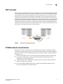

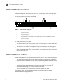


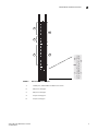


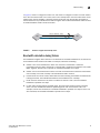

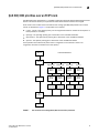


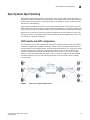


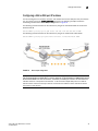
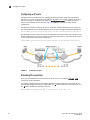
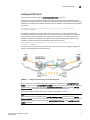


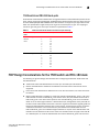
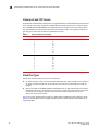
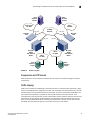


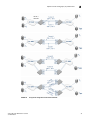


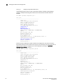
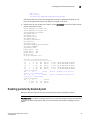

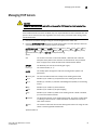


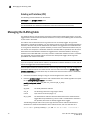


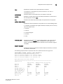


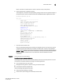


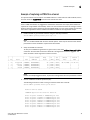
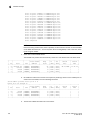


![ABiLINX 1101 取扱説明書[第5.4版]](http://vs1.manualzilla.com/store/data/006705938_2-cfec1f1deab6b23a53fc3bcbf103fd3e-150x150.png)