1
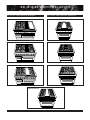
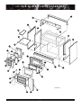
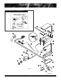
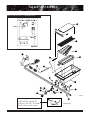
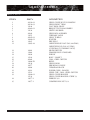
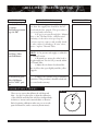
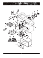
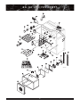
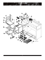
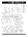
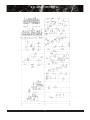
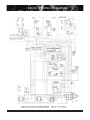
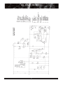
RD
PART LIST / SERVICE
MANUAL
A
PROFESSIONAL
48”, 36” & 30”
DUAL FUEL MODELS
DESI GN
R I CAN
ME
A
A
S
®
N
G S
S
O
O
TI
CE C I A D
R TIFIE
Retain this manual for future reference.
INTRODUCTION
with each appliance and should be consulted to check
for proper installation practices. Charges related to
Installation are not covered under warranty. Common
for a product this large and heavy is damage due to reckless handling by trucking firms, or Installation personnel
moving the product into position.
What follows is an overview of DCS warranty
provision. Review the warranty policy to determine what
is covered under the warranty repair provisions and what
will not be covered. Before beginning any work, the proposed service should either be authorized by DCS, or, in
the event the work is not covered under warranty, the
customer be informed of their responsibility for the
repair charges.
DCS SERVICE MANUAL
This service manual covers Models
DCS - (RD) - (36) (48) - (4) (6) - (GD) (GL) (GG)
DCS - (RD)-304
The DCS Professional Series of Dual Fuel
Ranges was designed to provide features tailored to a
customer with high expectations. This Service Guide
was created with the goal of minimizing customer
inconvenience and having any necessary repairs done
quickly and correctly. If, in the course of using this
manual, you should have any difficulty, or you feel
that some important item has been omitted, please let
us know with a phone call or Fax.
This manual was created for use by a qualified
technician, authorized by the DCS Service
Department.
To identify the Model and Serial #, locate and
read the appliance rating plate. The rating plate is
located on the rear left side of the interior top burner
box (remove the top burner grates and bowls), or on
the right side of the burner box on some six burner
models. In general, our Model numbering logic is as
follows;
1
2 3 4
ie. DCS-RD-484GG
1) (RD) denotes a Range with electric oven(s)
(27”& 24” self-cleaning) and an integral gas
cooktop.
2) (48)[47 7/8] , (36)[35 7/8] and (30)[29 7/8]
indicates unit nominal Width (in inches)
3) (4), or (6) indicates # of open top burners
4) (GG) indicates a Griddle and Char-Rock
Grill, (GD) indicates a thermostatically con
trolled Griddle section, or (GL) indicates a
Char-Rock Grill section.
Before servicing the range, it is first important to
accurately define the exact details of the com
plaint and then assess the cause of the defect.
Complete Installation Instructions are included
TA B L E
OF
CONTENTS:
Introduction / Warranty Introduction.....................1
Warranty Information.............................................2
Troubleshooting-General.........................................3
Orifice Hood / Pin Size Chart- L.P / Nat. Gas........3
Model Identification................................................4
Outer Body Parts..................................................5-6
RD-304 Outer Body Parts....................................7-8
Backguards.........................................................9-10
Open Top Burners Partlist..............................11-12
RD-304 Open Top Burners Partlist.................13-14
Troubleshooting - Leaks .......................................15
Troubleshooting - Open Top Burners ...................15
Griddle Partlist.................................................16-17
Troubleshooting - Griddle................................18-19
Grill Partlist......................................................20-21
Troubleshooting - Grill ...................................22-23
Location of Self-Clean & Bake Calibration Screws ...23
27”(48” & 36” Oven Partlist...........................24-25
24” (30”only) Oven Partlist............................26-27
12” (48”only) Small Oven Partlist...................28-29
Manifold Assembly-Size Item...................#32, Pg.12
Hardware Parts List..........................................Pg.30
RD48 Wiring Diagram.....................................Pg.31
RD48 Wiring Schematic...................................Pg.32
RD36 Wiring Diagram.....................................Pg.33
RD36 Wiring Schematic...................................Pg.34
RD304 Wiring Diagram...................................Pg.35
RD304 Wiring Schematic.................................Pg.36
1
WA R R A N T Y
This warranty covers the following cooktops and ranges:
DCS RD 484 GG, DCS RD 486 GL, DCS RD 486 GD, DCS RD 364 GD, DCS RD 366,
DCS RD 364 GL, & DCS RD 304.
L E N G T H O F WA R R A N T Y
One (1) Year Full - Covers the entire product
Five (5) Years Limited - Surface burners, Griddle burners, Grill burner, Oven burner
Ten (10) Years Limited - Porcelain oven, Porcelain inner door panels
D C S W I L L PAY F O R : :
All repair labor and replacement parts, for parts found to be defective, within the warranty period due to materials or workmanship.
Service must be provided by Authorized Factory Agent during
normal working hours.
D C S W I L L N OT PAY F O R : :
Installation or start-up
Normal adjustment to burners, gas regulators, etc.
Cleaning of igniters and/or general maintenance
Shipping damage
Service by an unauthorized agency. Damage or repairs due to service by an unauthorized agency or the use of unauthorized parts.
Overtime, weekends, holiday labor rates
Discoloration of the griddle plate
Improper installation, such as: no regulator, improper hook-up,
etc.
Chipping of porcelain enamel grates
Service visits to:
- Teach you how to use the appliance.
- Correct the installation. (You are responsible for providing electrical wiring, gas installation and other
connecting facilities.)
- Reset circuit breakers or replace home fuses.
- Damage caused from accident, abuse, alteration, mis
use, incorrect installation or installation not in accordance with local codes.
- Repairs due to other than normal household use.
- Units installed in non-residential applications such as:
day care centers, bed and breakfast centers, churches,
nursing homes, restaurants, hotels, schools, etc.
This warranty applies to appliances used in residential applications; it does not cover their use in commercial situations.This
warranty is for products purchased and retained in the 50 states of
the U.S.A., the District of Columbia and Canada. This warranty
applies even if you should move during the warranty period.
Should the appliance be sold by the original purchaser during the
warranty period, the new owner continues to be protected until
the expiration date of the original purchaser's warranty period.
This warranty gives you specific legal rights. You may also have
other rights which vary from state to state.
H OW TO O BTA I N S E RV I C E
For warranty service, contact your local DCS authorized service agency. Provide him with the Model #, Serial #, gas type
and date of installation, and a brief description of the problem. If you need assistance in locating the authorized service
agency in your area, contact your local dealer. He will have a listing of authorized DCS service agents in you area.
We want you to remain a satisfied customer. If a problem does come up that cannot be resolved to your satisfaction, please
let us know. Write: Dynamic Cooking Systems Inc., Customer Service Department, 5800 Skylab Road Huntington
Beach, CA 92647. Or call Direct Parts / Customer Service (888) 281-5698 or fax us at (714) 372-7001.
2
TROUBLESHOOTING
in pressure indicates a gas supply problem related to
installation, not covered by service warranty.
GENERAL INSTRUCTIONS:
CHECK ELECTRICAL SUPPLY
First, check to see if the electricity has been
turned on.
Next, check power to the cord in the back of
the range and at the wall receptacle. If power is OK
there, the next area to check will be at the service disconnect located behind the valve panel. The Valve
Panel can be removed by removing the five (5) screws
that hold it in place. Two (2) screws are located at
each end of the panel, while one (1) screw (painted
Red) behind a Burner Control knob must also be
removed before the valve panel can be removed.
Once the Valve Panel has been removed, unplug and
check for power to the female side of the plug. 220240V 120 between red /white 120 between black /
white 240 between red & black
Check for power at the Terminal Blocks,
(Black & Red = Live, White = Neutral)
STEP ONE: I S O L AT I N G T H E P RO B L E M
NOTE: Before addressing any specific problem the unit may have, it is advisable to help isolate
the nature of the problem by running a general check
of the 1) Gas Supply and 2) Electrical Supply. The
following procedure will narrow the possibilities and
help direct you to the source of the problem. A
detailed Troubleshooting section with specific symptoms and likely corrective courses of action follows
each sub-assembly Partlist section. Wiring diagrams
and schematics are also included to assist in troubleshooting.
CHECK GAS SUPPLY
First, check to see if the gas has been turned on.
Next, gain access to the regulator by removing
the grates over the cooktop burners on the far left
hand side of the cooktop. Beneath the grates, towards
the rear of the burner box, the regulator is located
between the manifold and rear incoming gas line.
Check the top of the regulator to see that it is set up
for the type of gas supplied to the unit. The cap on
top of the regulator indicates whether the unit is set
up for NATURAL or L.P. gas.
When the gas supply is on, check the gas
pressure with a manometer. The front main open top
burner orifice is the most convenient place to check
gas pressure. To access the main burner orifice,
remove the four (4) screws that hold the burner hanger down and A) move aside the burner assembly or B)
disconnect the igniter wires and remove the entire
burner / hanger assembly. Hook up a flexible line to
the main burner orifice, turn that burner on... the
pressure should read 5.0" W.C. for Natural Gas, and
10.0" W.C. for L.P. Gas. Turn on other burners and
check for an excessive drop in pressure. A large drop
ORIFICE or PIN SIZE References:
Gas Type
Incoming Pressure
Pressure Regulator
to Regulator
Supplies
NATURAL 7.0" to 9.0" W.C.
5.0" W.C.
L.P.
11" to 14.0" W.C.
10.0" W.C.
Orifice Size
Nat. (DMS)
Open Top
51
Center Simmer
75
Grill
48
Griddle
48
Small Oven
n/a
Large Oven
n/a
3
Pin Size Orifice Size
LP (DMS) LP (DMS)
58
50
79
80
55
55
55
55
n/a
n/a
n/a
n/a
RD MODEL IDENTIFICATION
48" DUAL FUEL RANGE MODELS:
36" DUAL FUEL RANGE MODELS:
MODEL DCS-RD-484 GG
MODEL DCS-RD-364 GD
MODEL DCS-RD-486 GL
MODEL DCS-RD-364 GL
MODEL DCS-RD-486 GD
MODEL DCS-RD-366
MODEL DCS-RD-304
OVEN ON
HEATING
DOOR LOCKED
4
HEATING
OUTER BODY PARTS ASSEMBLY
1
2
28
4
4A
23
27
3A
22
3
22A
19
18
26
8
17
10A
24
16
6
7
20
15
21
10
9
14
13
D
yn
a
m
ic
Co
ok
ing
Sys
t e ms
649FIG02.EPS
25
12
11
5
5
OUTER BODY PARTS LIST
PA RT S L I S T:
ITEM #
1
2
3
3A
4
4A
5
6
7
8
9
10
10A
11
11A*
12
13
14
15A
15
16
17
18
19
20
21
22
22A
23
24
25
26
27
28
*
PART #
DESCRIPTION
90104-01
90104-02
90300-01-PA
90300-03-PA
90300-02-PA
90531-01-PA
90531-03-PA
90531-02-PA
90303-01
90469-01
*90310-01
90303-02
90469-02
*90310-02
18052-2
90323
90551
150034-3
90186-01-PC
150034-1
14131
14045
90662-01
90184-05
17130-01
90187-02
18164-PL
90662-02
90184-06
90187-01
91254
90412
90403-PC
15001-39
15002-41
90658-02/90658-01
90658-03
90624/90623
90625
30313-3
150034-2
90470-02(R), 90470-01(L)
14138
16127
15002-41 (4)
14052
RD 48 LANDING LEDGE
RD 36 LANDING LEDGE
RD 484GG VALVE PANEL
RD 486GD VALVE PANEL
RD 486GL VALVE PANEL
RD 366 VALVE PANEL
RD 364GD VALVE PANEL
RD 364GL VALVE PANEL
RD 48 RIGHT BODY PANEL
RD 36 RIGHT BODY PANEL
RD 48 RIGHT SIDE INSUL. RET.
RD 48 LEFT BODY PANEL
RD 36 LEFT BODY PANEL
RD 48 LEFT SIDE INSUL. RET.
LEVELING LEG
RD 48 KICK PANEL ASSEMBLY
RD 36 KICK PANEL ASSEMBLY
HINGE RECEPTACLE
27" DOOR INSIDE LINER
27" OVEN DOOR HINGE
WINDOW PACK-27
WINDOW GASKET-27
27" Oven Door Panel Assy. (w/ Glass/Tape)
27” OVEN DOOR ASSEMBLY-Complete
DCS LOGO -LG-BLACK. (RANGES)
27" OVEN DOOR HANDLE
DOOR HANDLE ENDCAP
12" Oven Door Panel Assy. (w/ Glass/Tape)
12” OVEN DOOR ASSEMBLY-Complete
12" DOOR HANDLE
27" DOOR INSULATION RETAINER (RD 48/36)
12" DOOR INSULATION RETAINER
12" DOOR INSIDE PANEL
BOLT - DOOR HANDLE
SCREW - DOOR TOP
DRIP PAN - 48"
DRIP PAN - 36"
DRIP PAN HANDLE - 48"
DRIP PAN HANDLE - 36”
* ITEMS NOT PICTURED
6
DRIP PAN LINER (UNDER GRILL/ GRIDDLE ONLY)
12" OVEN DOOR HINGE
RD 36 SIDE COVER
WINDOW PACK-12” DOOR
LIGHT SWITCH - OVEN
FRONT PANEL SCREWS
OVEN DOOR GASKET (FRAME)
RD-304 OUTER BODY PARTS ASSEMBLY
1
2
19
4
4A
18
17
3A
3
8
10
10A
14
6
7
15
5
16
9
20
13
649FIG20.EPS
12
11
7
RD-304 OUTER BODY PARTS LIST
PA RT S L I S T:
ITEM #
PART #
DESCRIPTION
1
90104-03
LANDING LEDGE
2
90440-PA
VALVE PANEL
3
90432-01
RIGHT BODY PANEL
3A
90431-01
RIGHT SIDE INSUL. RET.
4
90432-02
LEFT BODY PANEL
4A
90431-02
LEFT SIDE INSUL. RET.
5
18052-2
LEVELING LEG
6
90758
KICK PANEL ASSEMBLY
7
150034-3
HINGE RECEPTACLE
8
90766-01-PC
DOOR INSIDE LINER
9
150034-1
OVEN DOOR HINGE
10
14131
WINDOW PACK
10A
14045
WINDOW GASKET
11
90765-12
Oven Door Panel Assy. (w/ Glass/Tape)
11A*
90765-02
OVEN DOOR ASSEMBLY-Complete
12
17130-01
DCS LOGO -LG-BLACK. (RANGES)
13
90187-02
OVEN DOOR HANDLE
14
90561
DOOR INSULATION RETAINER
15
15001-39
BOLT - DOOR HANDLE
16
15002-41
SCREW - DOOR TOP
17
90772
DRIP PAN ASSEMBLY
18
16127
LIGHT SWITCH-OVEN
19
15002-41
FRONT PANEL SCREWS
20
18164-PL
DOOR HANDLE ENDCAP
*
14052
OVEN DOOR GASKET
* ITEMS NOT PICTURED
8
BACK GUARDS ASSEMBLY
22” DUAL FUEL RANGE HIGH SHELF BACKGUARD
1
2
4
DCS-HSRD-48R
DCS-HSRD-36R
DCS-HSRD-30R
5
3
12” DUAL FUEL RANGE LOW BACK BACKGUARD
6
2
7
DCS-LBRD-48R
DCS-LBRD-36R
DCS-LBRD-30R
DUAL FUEL RANGE ISLAND TRIM BACKGUARD
8
9
DCS-ITRD-48R
DCS-ITRD-36R
DCS-ITRD-30R
649FIG07.EPS
9
BACK GUARDS ASSEMBLY
PA RT S L I S T:
ITEM #
PART #
90089-03
90089-04
90089-05
RD 48 HIGH SHELF BACK SHEET
RD 36 HIGH SHELF BACK SHEET
RD 30 HIGH SHELF BACK SHEET
2
90041-03
90041-04
90041-05
RD 48 TOP COVER
RD 36 TOP COVER
RD 30 TOP COVER
3
90087-03
90087-04
90087-02
RD 48 HIGH SHELF FRONT SHEET
RD 36 HIGH SHELF FRONT SHEET
RD 30 HIGH SHELF FRONT SHEET
4
90240-01
90240-02
90240-03
RD 48 HIGH SHELF WELD ASSY.
RD 36 HIGH SHELF WELD ASSY.
RD 30 HIGH SHELF WELD ASSY.
5
90241-01
90241-02
90241-03
RD 48 HIGH SHELF BOTTOM ENCLOSURE
RD 36 HIGH SHELF BOTTOM ENCLOSURE
RD 30 HIGH SHELF BOTTOM ENCLOSURE
6
90040-03
90040-04
90776
RD 48 LOW BACK BACK SHEET
RD 36 LOW BACK BACK SHEET
RD 30 LOW BACK BACK SHEET
7
90038-03
90038-04
90038-02
RD 48 LOW BACK FRONT SHEET
RD 36 LOW BACK FRONT SHEET
RD 30 LOW BACK FRONT SHEET
8
90245-04
90245-05
90245-03
RD 48 ISLAND TRIM CAP
RD 36 ISLAND TRIM CAP
RD 30 ISLAND TRIM CAP
9
90248-04
90248-05
90248-03
RD 48 ISLAND TRIM BACK SHEET
RD 36 ISLAND TRIM BACK SHEET
RD 30 ISLAND TRIM BACK SHEET
1
DESCRIPTION
10
OPEN TOP BURNER ASSEMBLY
E L E C T R I C A L S C H E M AT I C :
OPEN TOP
IGNITERS
120 VAC
60 Hz.
I PH.
I
2
3
SPARK
MODULE
NO
4
NO
3
SPARK
MODULE
NO
2
NO
I
UNITS WITH
(6) OPEN TOP
BURNERS ONLY
1
*IT IS CRITICAL FOR PROPER PERFORMANCE THAT THE SWITCHES
SUPPLYING POWER TO THE SPARK MODULE ARE PLUGGED INTO
THE SAME NUMBER TERMINAL AS THE ELECTRODE SERVING THE
BURNER IS PLUGGED INTO (e.g.- OPEN TOP SPARK IGNITER OUTPUT
#1 MUST BE ON THE SAME BURNER SERVED BY THE OPEN TOP
SWITCH PLUGGED INTO POWER INPUT # 1
2
3
5
6
9
28
8
7
4
27
19
32
10
18
15
16
17
11
12
13
26
20
25
21
29
23
31
24
22
30
11
14
649FIG04.EPS
OPEN TOP BURNER ASSEMBLY
PA RT S L I S T:
ITEM #
1
2
3
4
5
6
7
8
9
10
11
12
13
14
15
16
17
18
19
20
21
22
23
24
25
26
27
28
29
30
31
32
PART #
12112-01
12131-PC
12139
12138
12105-PC
12093
12094
15001-22
15002-26
14000
12113
90653-02-PL
15021-04
13236
90653-01-PL
12114
16006
15109
16212
13071
14006-PL
14125
14124
13070
13005-80
13005-87
13005-58
13005-51
13228
90129
90085-01
90084-01
90324
90324-01
90324-02
90324-03
90324-05
90324-06
12111
13003
DESCRIPTION
TOP HALF GRATE
SIMMER TUBE CAP
SIMMER BURNER CAP
SIMMER BURNER BASE
AERATION BOWL
ELECTRODE ASSEMBLY
ELECTRODE SPRING CLIP
BURNER BASE SCREWS
VENTURI BOLT
VENTURI GASKET
MAIN VENTURI, REAR
SIMMER VENTURI, REAR
VENTURI NUT
SPARK MODULE
SIMMER VENTURI, FRONT
MAIN VENTURI, FRONT
TERMINAL BLOCK
VALVE SCREW / PLUG / WASHER
POWER CORD - RANGES
SPARK SWITCH / SIMMER, STD. BURNER
BEZEL
SIMMER BURNER KNOB
SIMMER BLOCK O-RING
SIMMER BLOCK
SIMMER ORIFICE HOOD, LP GAS
SIMMER ORIFICE HOOD, NATURAL GAS
ORIFICE HOOD, LP GAS
ORIFICE HOOD, NATURAL GAS
MAIN BURNER VALVE
BURNER HANGER
GRATE SUPPORT (3/4” WIDE) (L/R)
GRATE SUPPORT (1 1/2” WIDE) (CENTER)
MANIFOLD ASSEMBLY (Complete w/Valve/Regulator)
DCS-RD-484GG
DCS-RD-486GL
DCS-RD-486GD
DCS-RD-366
DCS-RD-364GL
DCS-RD-364GD
AIR SHUTTER SIMMER
REGULATOR
NOTE: Burner Base Assembly Front – 90146-01 (includes item # 2,3,4,6,7,10,11,12)
Burner Base Assembly Rear – 90146-02 (includes item # 2,3,4,6,7,10,11,12,15,16)
12
RD-304 OPEN TOP BURNER ASSEMBLY
E L E C T R I C A L S C H E M AT I C :
120 VAC
60 Hz.
1 PH.
1
2
3
SPARK
MODULE
NO
4
1
NO
3
2
NO
I
L
N
NO
2
3
*IT IS CRITICAL FOR PROPER PERFORMANCE THAT THE SWITCHES
SUPPLYING POWER TO THE SPARK MODULE ARE PLUGGED INTO
THE SAME NUMBER TERMINAL AS THE ELECTRODE SERVING THE
BURNER IS PLUGGED INTO (e.g.- OPEN TOP SPARK IGNITER OUTPUT
#1 MUST BE ON THE SAME BURNER SERVED BY THE OPEN TOP
SWITCH PLUGGED INTO POWER INPUT # 1
5
6
9
36
8
7
4
27
10
35
11
31
33
13
16
12
30
15
32
14
18
17A
17B
34
26
29
19
25
20
649FIG21.EPS
24
22
23
28
21
13
RD-304 OPEN TOP BURNER ASSEMBLY
PA RT S L I S T:
ITEM #
PART #
1
2
3
4
5
6
7
8
9
10
11
12
13
14
15
16
17A
17B
18
19
20
21
22
23
24
25
26
27
28
12112-01
12131-PC
12139
12138
12105-PC
12093
12094
15001-22
15002-26
14000
12113
90653-02-PL
15021-04
13236
90653-01-PL
12114
16006
16006
15109
13071
14006-PL
14125
14124
13070
13005-75/79
13005-51/58
13228
90129
90765-42
29
30
31
32
33
34
35
36
90704
90705
18018-13
18018-11
18041
90566
90565
90085-01
DESCRIPTION
TOP HALF GRATE
SIMMER TUBE CAP
BURNER CAP
BURNER BASE
AERATION BOWL
ELECTRODE ASSEMBLY
ELECTRODE SPRING CLIP
BURNER BASE SCREWS
VENTURI BOLT
VENTURI GASKET
MAIN VENTURI, REAR
SIMMER VENTURI, REAR W/A
VENTURI NUT
SPARK MODULE
SIMMER VENTURI, FRONT W/A
MAIN VENTURI, FRONT
TERMINAL BLOCK
TERMINAL BLOCK W/CENTER JUMPER REMOVED
VALVE SCREW / PLUG / WASHER
SPARK SWITCH / SIMMER, STD. BURNER
BEZEL
SIMMER BURNER KNOB
SIMMER BLOCK O-RING
SIMMER BLOCK
SIMMER ORIFICE HOOD, NATURAL GAS/LP
MAIN ORIFICE HOOD, NATURAL GAS/LP
MAIN VALVE
BURNER HANGER
MANIFOLD ASSEMBLY
(Complete w/Valves/Regulator & Intake pipe).
AIR DUCT BOTTOM
AIR DUCT TOP
INTAKE PIPE
PIPE 1/2 NPT
1/2 ELBOW FEMALE
BRACKET GAS PIPE SPACER
BRACKET GAS PIPE RETAINER
GRATE SUPPORT
14
LEAK / OPEN TOP TROUBLESHOOTING
P RO B L E M A R E A :
W H AT TO D O :
Customer smells gas at
all times
CHECK for LEAKS at:
A) The two brass elbows coming from the
1/2"NPT pipe between the regulator and manifold
B) Along the manifold at every nut/washer
point and plug
C) At all connection points between tubing
and thermal valves at grill and griddle locations.
Customer smells gas
only when Open Top
Burners, Large Oven,
or Grill are in operation
CHECK for LEAKS at:
A) The Thermal Valve and connections supplying the Grill, with Grill turned on.
B) O-Ring between the Simmer Block and
Simmer Valve for all Open Top Burners, with burners on.
Open Top Burner
Doesn't Light
Is the igniter sparking? The spark should be
?
jumping to the simmer burner cap.
A) Make sure that the lead to the electrode is
secure, as well as the lead to the Spark Module and
that there is power also.
B) Spark Switches at control knobs should be
checked for power to and coming out from (with
knob in "lite" position. If there is power going to, yet
not coming out the other side, replace spark switch.
C) See Open Top Burner Lighting and
"Adjustable Low Setting" sections in the Installation
Manual.
15
U S E F U L N OT E S :
NOTE: If using a
soap and water solution
when checking for
leaks, be careful not to
get any water on Spark
Switches, as doing so
will cause a short in the
switch.
NOTE: It is important
that correct # wire be
traced from the Spark
Switch,to the Spark
Module, to the Burner
Electrode.
GRIDDLE ASSEMBLY
E L E C T R I C A L S C H E M AT I C :
1
25
L N
2
3
22
4
21
5
6
20
7
16
26
15
23
17
8
18
19
14
9
13
24
649FIG08.EPS
12
27
10
28
11
649FIG08.EPS
16
GRIDDLE ASSEMBLY
PA RT S L I S T:
ITEM #
PART #
1
2
3
4
5
6
7
8
9
10
11
12
13
14
15
16
17
18
19
20
21
22
23
24
90253-02
90582
90192-01
90195
90133
12005-1
16009-1
90141
30313-3
90746-04
13073
18017
18166
18165
15109
16046-02
13310
14006-PL
14129
16077
16006
16212
16077
13005-48
13005-55
25
18204-01
15139
16046-02
18077-2
18077-1
26
27
28
DESCRIPTION
GRIDDLE COVER
GRIDDLE FLUE COVER
GRIDDLE / GRILL FRONT TRIM
GRIDDLE FRONT TRIM
GRIDDLE PLATE ASSEMBLY
GRIDDLE BURNER
IGNITER
GRIDDLE BAFFLE
DRIP PAN LINER
GRIDDLE TUBING
THERMAL VALVE
ELBOW ASSEMBLY
MANIFOLD ADAPTER
PIPE PLUG
VALVE SCREW / PLUG / WASHER
INDICATOR LIGHT
GRIDDLE THERMOSTAT
BEZEL
GRIDDLE THERMOSTAT KNOB
FIBER GLASS SLEEVE
TERMINAL BLOCK
POWER CORD
FIBER GLASS SLEEVE
ORIFICE HOOD-NATURAL GAS (#48 DMS)
[ORIFICE PIN-LP GAS (#55 DMS)
(INTEGRAL TO THERMAL VALVE)]
GRIDDLE COVER HANDLE
GRIDDLE COVER HANDLE SCREW (2)
INDICATOR LIGHT LENS
FERRULE 3/8
COMPRESSION NUT 3/8
17
GRIDDLE TROUBLESHOOTING
P RO B L E M A R E A :
Griddle will not
operate
W H AT TO D O :
CHECK 1) the Electrical / Gas Supply as outlined in the General Instruction section.
2) Remove Griddle plate assembly (fastened by 2 screws in the front and 1 screw in
the back, under the flue cover- Visually check
for igniter breakage. If igniter is broken,
remove / replace
3) Remove Valve Panel (see General
instructions and note removal of "Red" screw
behind control knob - not on all units)
4) 120 V supplied to Thermostat from
the terminal block ?(live= black) If not, troubleshoot power supply lines, If YES,
5) Disconnect power, Remove wires off
Thermostat & check for continuity between
Thermostat terminals when Thermostat dial is
rotated to the ON. If there is no continuity
remove / replace Thermostat.
6) If Thermostat is OK, Remove the
wires from the Thermal Valve and check for
continuity between the two (2) terminals on
the face of the valve. If none, remove / replace.
7) If the Thermal Valve is OK, Remove
the wires from the Griddle Igniter and check
the igniter leads for continuity. If none, remove
/ replace igniter.
8) If the Igniter is OK, Check the
Neutral Return Wire for continuity to the neutral (white) wire of the power supply cord.
U S E F U L N OT E S :
NOTE: Be careful not
to damage the
Capillary when removing the Griddle plate
assembly
?
Griddle still will not
operate, (Electrically
operational - Steps 1-8
OK)
1) Verify Gas supply to the unit. Turn
the Gas supply OFF. Loosen tubing supplying
gas from the manifold to the Thermal Valve at
the Thermal Valve. Quickly turn manual valve
On, then Off while an assistant listens closely
for the sound of flowing gas at the loosened
end of the connection. If gas is not flowing,
check the tubing for blockage.
18
NOTE: -Ensure at the
supply source that the
live and neutral wires
are not reversed ( If
they are, this would not
be covered under warranty)
GRIDDLE TROUBLESHOOTING
P RO B L E M A R E A :
W H AT TO D O :
(Cont'd)-Griddle still
will not operate,
(Electrically operational
Steps 1-8 OK)
If dirt or other foreign matter is blocking gas
flow, then the supply line should be disconnected and the line purged. This procedure is
not covered under warranty.
2) If gas is present at the Manual Valve,
and Electrical continuity of the valve exists per
Step 6)- (previous section), remove and visually
check the valve orifice for blockage. If none
exists, remove / replace Thermal Valve
Low Flame / Heat
from Griddle Burner
CHECK 1) Gas pressure and supply as outlined in
the "General" section.
2) Ensure the orifice hood is not tightened
down onto the L.P. jet nested within the Thermal
Valve.
3) Adjust the air shutter closed until the
flame is yellow, then open slightly until the yellow
disappears.
GRIDDLE
CALIBRATION
1) To calibrate the Griddle Thermostat, place
a reliable griddle thermometer on the center of the
griddle plate. Rotate the thermostat to 350ºF. After 3
burner cycles, the griddle plate should have reached
equilibrium.
2) (You'll need a knob with a hole drilled
through the center to allow a flat-tipped screwdriver to
be inserted through it.) With the knob in place, insert
a thin blade, flat-tipped screwdriver through the
knob and nest it into the small slotted screw in the
thermostat (it may be necessary to clear the screw of
a small amount of sealant)
3) Note the temperature shown on the griddle thermometer, then, while holding the screw still
with the screwdriver, rotate the knob to the thermometer temperature. DO NOT TURN THE
CALIBRATION SCREW. Reset the temperature
and check for accuracy. Repeat if necessary.
19
U S E F U L N OT E S :
NOTE: Before calibrating the Thermostat,
ensure that the griddle
sensing bulb is placed
within the small "V"
tube welded directly to
the bottom of the griddle plate, pushed about
halfway back. The larger piece of angle iron is
for flame diffusion, not
for placement of the
sensing bulb.
GRILL ASSEMBLY
E L E C T R I C A L S C H E M AT I C :
1
LIVE
23
2
3
NEUTRAL
4
21
5
9
20
19
15
25
24
14
22
6
11
7
16
8
13
17
12
18
649FIG09.E
10
*Power is supplied to the igniter
& thermal valve through the
"common" and "NC" (normally
closed) contacts of the switch
COM
20
NC
NO
649FIG09.EPS
GRILL ASSEMBLY
PA RT S L I S T:
ITEM #
PART #
1
2
3
4
5
6
7
8
9
10
11
90254-02
90192-03
12148
90262-01
12134
90042
13073
90045-02
16009-01
18165
13005-48
12
13
14
15
16
17
18
19
20
21
22
23
16001
13068
18030
15109
90260
14006-PL
14130
16077
16006
16212
15112
18204-01
15139
18077-2
18077-1
24
25
DESCRIPTION
GRILL COVER W/ PULL HANDLE
GRILL FRONT TRIM
CAST IRON GRATE
BRIQUETTE TRAY ASSEMBLY
GRILL U-BURNER
GRILL BOX ASSEMBLY
THERMAL VALVE
GRILL TUBING
IGNITER
PIPE PLUG
ORIFICE HOOD-NAT. GAS (#48 DMS)
ORIFICE PIN-L.P. GAS (#55 DMS)
(INTEGRAL TO THERMAL VALVE)
MICROSWITCH
SIMMER VALVE-STANDARD
ELBOW
BOLT / GASKET
CAM - GRILL SWITCH
BEZEL
GRILL KNOB
FIBERGLASS SLEEVE
TERMINAL BLOCK
POWER CORD - RANGES
SPEED CLIP - CAM - GRILL SWITCH
GRILL COVER HANDLE
GRILL COVER HANDLE SCREW (2)
FERRULE 3/8
COMPRESSION NUT 3/8
21
GRILL TROUBLESHOOTING
P RO B L E M A R E A :
Grill will not operate
W H AT TO D O :
CHECK 1) the Electrical / Gas Supply as outlined in the General Instruction section.
2) Remove Grill racks and the radiant
tray- visually check for igniter breakage
3) Remove Valve Panel (see General
instructions and note removal of "Red" screw
behind control knob- not on all units)
4) 120 V supplied to "C"(common) terminal of Valve Switch?
5) Disconnect power, Remove wire from
"NC"(normally closed) terminal & check for
continuity between "C" and "NC" when valve
is rotated to the "ON" position. If none is,
switch positioned so that the tab on the valve
stem activates the switch when the knob is in
"OFF" (thus de-energizing to NC contact) ?
Test the switch manually, if non-operational,
remove / replace.
6) If switch is OK, Remove the wires
from the Thermal Valve and check for continuity between the two (2) terminals on the face of
the valve. If none, remove / replace.
7) If the Thermal Valve is OK, Remove
the wires from the Grill Igniter and check the
igniter leads for continuity. If none, remove /
replace igniter.
8) If the Igniter is OK, Check the
Neutral Return Wire for continuity to the neutral (white) wire of the power supply cord.
U S E F U L N OT E S :
?
Grill still will not
operate, (Electrically
operational - Steps 1-8
OK)
1) Verify Gas supply to the unit, Loosen
tubing supplying gas from the manual "on-off "
valve to the Thermal Valve at the Thermal
Valve. Quickly turn manual valve On, then Off
and listen closely for the sound of flowing gas.
If gas is not flowing, shut off gas supply, and
check the tubing for blockage.
22
NOTE: -Ensure at the
supply source that the
live and neutral wires
are not reversed ( If
they are, this would not
be covered under warranty)
GRILL TROUBLESHOOTING
P RO B L E M A R E A :
W H AT TO D O :
U S E F U L N OT E S :
(Cont'd)-Grill still will
not operate,
(Electrically operational
Steps 1-8 OK)
If dirt or other foreign matter is blocking gas
flow, then the supply line should be disconnected and the line purged. This procedure is
not covered under warranty.
2) If gas is present through the Manual
Valve, to the Thermal Valve, and Electrical
continuity of the valve exists per Step 6)
(previous section), remove and visually check
the valve orifice for blockage. If none exists,
remove / replace Thermal Valve
Low Flame / Heat
from Grill Burner
CHECK 1) Gas pressure and supply as outlined in
the "General" section.
2) If natural gas, ensure the orifice hood is
not tightened down onto the L.P. jet nested within
the Thermal Valve.
3) Adjust the air shutter closed until the
flame is yellow, then open slightly until the yellow
disappears.
Too much Heat given
off by Grill Burner
when in "LOW" position.
1) Adjust center simmer screw per Installation
Instructions. (This procedure is Installer related and
not covered under warranty)
C A L I B R AT I O N S C R E W S :
FIG.01
There are two screws that calibrate the self-clean and
bake. -See fig.01 on the right, to adjust the calibration
of the self-clean and bake turn each screw independently
clockwise to increase and counterclockwise to decrease.
Before beginning calibration make sure you use an adequate thermometer (such as a mercury thermometer).
23
SELF-CLEAN
BAKE
27” OVEN PARTS
9
36
8
35
34
41
10
32
13
14
11
12
33
3
2A
2
2A
4
37
18
7
2B
2C
15
1
5
22
27
23
24
25
PRO
OF
26
CLE
AN
17
5A
21
28
40
39
29
30
31
38
16
6
649FIG01.EPS
24
27” OVEN PARTLIST
PA RT S L I S T:
ITEM #
1
2
2A
2B
2C
3
3A
4
5
5A
6
7
8
9
10
11
12
13
14
15
16
17
18
*
*
21
22
23
24
25
26
27
28
29
30
31
32
33
34
35
36
37
38
39
40
41
*
PART #
DESCRIPTION
90947-01
90947-02
90484
90459
90408
90527-01
90527-02
16001
91162
16028-2
16030-2
90515
90305-PC
15226
16032-1
16212
16046-02
16077
13037
14006-PL
14126-01
50135
90392 - PC
13043
16242
90478
90237
50151-8
13038
16044-1
16044-2
13039
13039
16045-2
16045-2
16045-2
16045-3
16049
50166
16038
16148
16155
16147
16031
12063
19048
19003-02
14051-01
14052
SLIDE RACK SUPPORT WELD ASS’Y (L/H)
SLIDE RACK SUPPORT WELD ASS’Y (R/H)
BRACKET MICROSWITCH - INTERLOCK
PUSH ROD 3/8”- INTERLOCK
PUSH ROD BRACKET - INTERLOCK
EDGE GUARD (L/H)
EDGE GUARD (R/H)
MICROSWITCH - INTERLOCK
PUSH ROD SWITCH - INTERLOCK
BROIL ELEMENT 4,000 WATT
BAKE ELEMENT 6,000 WATT
BAKE ELEMENT SUPPORT ASS’Y
CONVECTION BAFFLE
THUMBSCREW - RACK SUPPORT
5 PUSH-BUTTON SELECTOR SWITCH
POWER CORD
INDICATOR LIGHT
FIBERGLASS SLEEVE
THERMOSTAT KS-HT
BEZEL
KNOB OVEN - SELF CLEAN
CAPILLARY BULB SUPPORT
27” OVEN TANK ASSEMBLY
HIGH TEMP CUT-OUT
OVEN LAMP ASSEMBLY
GUIDE CENTER DRIP PAN
GUIDE DRIP PAN
ELECTRICAL CONTROL BOX
50% PULSER
12” OVEN TIMER-PROOF
27” OVEN TIMER-CLEAN
12” OVEN HOT WIRE RELAY
27” OVEN HOT WIRE RELAY
FLANGE MOUNT RELAY DPDT
FLANGE MOUNT RELAY DPDT
FLANGE MOUNT RELAY DPDT
FLANGE MOUNT RELAY TPDT
TERMINAL BLOCK
BLOWER MOTOR
AIR INTERLOCK SWITCH
WHEEL BLOWER
WHEEL COOLING RVCR 8712-100 HS
MOTOR - CONVECTION RD
MOTORIZED DOOR LOCK
CATALYST
OVEN RACK LARGE OVEN
OVEN RACK SMALL OVEN
BUTTON PUSH
OVEN DOOR GASKET
* ITEMS NOT PICTURED
25
RD-304 24” OVEN PARTS
9
8
10
22
12
13
23
11
3
26
2
32
4
25
41
3A
7
15
2A
2B
33
1
5
5a
17
18
30
16
14
19
39
20
24
21
42
38
37
36
35
29
649FIG22.EPS
43
34
31
28
6
26
40
RD-304 24” OVEN
PA RT S L I S T:
ITEM #
1
2
2A
2B
3
3A
4
5
5A
6
7
8
9
10
11
12
13
14
15
16
17
18
19
20
21
22
23
24
25
26
27
28
29
30
31
32
33
34
35
36
37
38
39
40
41
42
43
PART #
DESCRIPTION
90407-01
90407-02
90754
90459
90525-01
90527-02
90529
90728
16248
16158
16265
90750-PC
15226
16032-1
16212
16046-02
13234
14006-PL
14190
13043
16242
90751
13038
16044-2
16045-2
16045-3
16049
90165
16038
50166-01
16247
13233
14052
90802
15003-26
15029
90759-PC
90404-01
90404-02
16130
90171
90170
90285
16053
90276
90771
90789
19048-01
12063
SLIDE RACK SUPPORT WELD ASS’Y (L/H)
SLIDE RACK SUPPORT WELD ASS’Y (R/H)
BRACKET MICROSWITCH - INTERLOCK
PUSH ROD 3/8”- INTERLOCK
EDGE GUARD (L/H)
EDGE GUARD (R/H)
MICROSWITCH - W/A INTERLOCK
LIFT CHANNEL - INTERLOCK
BROIL ELEMENT
BAKE ELEMENT
BAKE ELEMENT INNER
CONVECTION BAFFLE
THUMBSCREW - RACK SUPPORT
5 PUSH-BUTTON SELECTOR SWITCH
POWER CORD
INDICATOR LIGHT
T-STAT MAIN OVEN E/R 35
BEZEL
KNOB OVEN - SELF CLEAN
HI-TEMP CUT-OUT
OVEN LAMP ASSEMBLY
ELECTRICAL CONTROL BOX ASSEMBLY
50% PULSER
OVEN TIMER - CLEAN
FLANGE MOUNT RELAY DPDT
FLANGE MOUNT RELAY TPDT
TERMINAL BLOCK
CONVECTION MOTOR ASSEMBLY
AIR INTERLOCK SWITCH
BLOWER MOTOR
MOTORIZED DOOR LOCK
T-STAT E/R 25
OVEN DOOR GASKET (ITEM NOT PICTURED)
CLIP OVEN SEAM
HEX BOLT 1/4-20 X 3.5 SS
NUT W/RET. 1/4-20
OVEN TANK W/A
BRACKET INTERLOCK UPPER L/H
BRACKET INTERLOCK UPPER R/H
CONVECTION BLADE
MOTOR COVER PAD
MOTOR INSULATION PAD
MOTOR PAD
MOTOR COOLING BLADE
BRACKET MOTOR
BRACKET CHANNEL
REFLECTOR
OVEN RACK RD-304
CATALYST
27
12” OVEN
9
11
30
8
1
10
14
19
3
12
4
31
13
15
5
7
22 23
16
6
24 17
18
25
PROO
F
CLEA
26
N
21
27
28
2
29
649FIG03.EPS
28
649FIG03.EPS
12” OVEN
PA RT S L I S T:
ITEM #
1
2
*
3
4
5
6
7
8
9
10
11
12
13
14
15
16
17
18
19
*
21
22
23
24
25
26
27
28
29
30
31
PART #
DESCRIPTION
19004-1
19003-2
50086
50087-1
16029-02
16027-2
50011-01-PC
50096
16032-2
16212
16046-02
16077
13037
14006-PL
14126-02
50135
50058-PC
13043
16242
50018-2
14053
50151-8
13038
16044-1
16044-2
13039
13039
16045-2
16045-3
16049
50166
16038
12” OVEN RACK SUPPORT
12” OVEN RACK
HEAT ELEMENT CLIP
BRACKET - RACK
BROIL ELEMENT 3,600 WATTS
BAKE ELEMENT 3,700 WATTS
OVEN BOTTOM PAN
CLIP- OVEN SEAM
4 PUSH-BUTTON SELECTOR SWITCH
POWER CORD
INDICATOR LIGHT
FIBERGLASS SLEEVE
THERMOSTAT KS-HT
BEZEL
KNOB 12” OVEN
CAPILLARY BULB SUPPORT
12” OVEN TANK ASSEMBLY
HIGH TEMP CUT-OUT
OVEN LAMP ASSEMBLY
REFLECTOR
OVEN DOOR GASKET
ELECTRICAL CONTROL BOX
50% PULSER
12” OVEN TIMER-PROOF
27” OVEN TIMER-CLEAN
12” OVEN HOT WIRE RELAY
27” OVEN HOT WIRE RELAY
FLANGE MOUNT RELAY DPDT
FLANGE MOUNT RELAY TPDT
TERMINAL BLOCK
BLOWER MOTOR
AIR INTERLOCK SWITCH
* = ITEMS NOT PICTURED
29
HARDWARE
PA RT S L I S T:
ITEM #
1
2
3
4
5
6
7
8
9
10
11
12
13
14
15
16
17
18
19
20
21
22
23
24
25
PART #
DESCRIPTION
15002-41 (4)
15001-09
15001-29
15029-02
15002-32
15002-41
15001-39
15001-04
15001-05
15003-16
15104
15002-26
15109
15003-01
15001-41
15002-04
15021-07
15001-22
15001-03
90417
15001-33
15117
15003-26
15029
15001-23
FRONT PANEL SCREWS
KICK PANEL / SIDE PANEL SCREWS
KNOB / BEZEL
VALVE PANEL NUT
LEVELING SCREW
DOOR TOP - SCREW
BOLT - DOOR HANDLE
HARDWARE BAG B/GUARD, I-TRIM SCREW
HARDWARE BAG B/GUARD, I-TRIM SCREW
HARDWARE BAG B/GUARD HEX BOLT ZN
HARDWARE BAG B/GUARD WASHER ZN
VENTURI BOLT
VALVE SCREW / PLUG / WASHER
MANIFOLD BOLT HEX
SELECTOR SCREW
IGNITER SCREW GRIDDLE
IGNITER KEPS NUT GRIDDLE
GRIDDLE BURNER SCREW
RELAY SCREW
BAFFLE SCREW SPACER
BAFFLE SCREW
THUMB SCREW RACK SUPPORT
MOTOR COVER PAD BOLT HEX
BRACKET CHANNEL NUT W/RETAINER
ELEMENT SCREW
30
RD48 WIRING DIAGRAM
NOTES: (many of the parts have the name of the part instead of the
abbreviation)
AIS
BK-12
BK-30
BM
BLT
31
=
=
=
=
=
AIR INTERLOCK SWITCH (16038)
BAKE ELEMENT 12 (16027-2)
BAKE ELEMENT 30 (16030-2)
BLOWER MOTOR (50166)
BLOWER THERMOSTAT (16041)
BR-12
BR-30
BS
CF
CM
CR
CT
DPS
ELE
FMR-DPDT
FMR-TPDT
GV
GT
GS
HTC
HWR
IGN
K1
K2
K4
LM
LS
MDFRM
MDL
MPS
OL
PL
PLSR
PT
PP
RF
RIS
RR
RRM
S-12
S-30
TB-MAIN
TB-PANEL
T-STAT
=
=
=
=
=
=
=
=
=
=
=
=
=
=
=
=
=
=
=
=
=
=
=
=
=
=
=
=
=
=
=
=
=
=
=
=
=
=
=
BROIL ELEMENT 12 OVEN (16029-2)
BROIL ELEMENT 30 (16028-2)
BURNER SWITCHES (13071)
CENTER FRONT
CONVECTION MOTOR
CENTER REAR
CLEAN TIMER (16044-2)
COOR POSTION SWITCH
ELECTRODE (12093)
FLANGE MOUNT RELAY DPDT (16045-2)
FLANGE MOUNT RELAY TPDT (16045-3)
GRIDDLE & GRILL VALVE (13073)
GRIDDLE THERMOSTAT (13310)
GRILL SWITCH (16001)
HI-TEMP CUT-OUT (13043)
HOT WIRE RELAY (13039)
IGNITER (SMALL) (16009-1)
CLEAN REALY DPDT
PROOF RELAY DPDT
LATCH OPEN RELAY DPDT
LATCH MOTOR, DOOR
LIGHT SWITCH (16127)
MOTOR DUAL FUEL RD MODEL(16147)
MOTORIZED DOOR LOCK (16031)
MOTOR POSITION SWITCH
OVEN LIGHT (16242)
PILOT LIGHT (16046-02)
PULSER 50% (13038)
PROOF TIMER (16044-1)
PRONG PLUG 50A (16212)
RIGHT FRONT
RACK INTERLOCK SWITCH
RIGHT REAR
REAR REIG MODULE (13236)
SELECTOR 12” (16032-2)
SELECTOR 30” (16032-1)
TERMINAL BLOCK – MAIN (16049)
TERMINAL BLOCK – PANEL (16006)
THERMOSTAT KS-HT (16032-2)
RD 48 SCHEMATIC
32
RD 36 WIRING DIAGRAM
33
RD 36 SCHEMATIC
34
RD 304 WIRING DIAGRAM
35
RD 304 SCHEMATIC
36
As product improvement is an ongoing
process at DCS, we reserve the right to change
specifications or design without notice.
Litho in USA 06-03
Part No. 10649 REV 4
5800 Skylab Road Huntington Beach, CA 92647
(714) 372-7000
Fax (714) 372-7001
Direct Parts/Customer Care Center (888) 281-5698