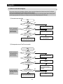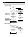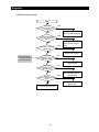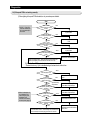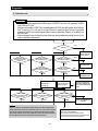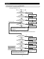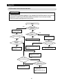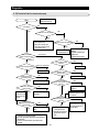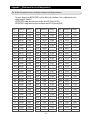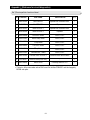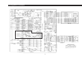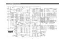
1
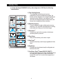
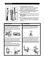
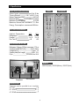
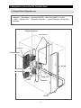
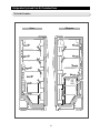
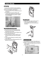
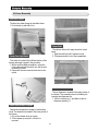
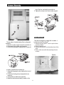
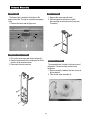
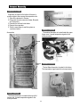
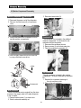
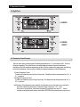
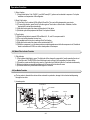
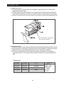
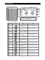
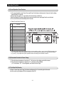
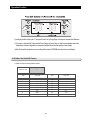
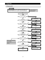
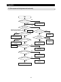
SAMSUNG Home Appliance Service
For the latest parts information,
Please access to our service web site
(http://www.e4buyer.com/refrigerator)
SIDE-BY-SIDE REFRIGERATOR
Model:
RS2533SW
SAM0058
1. INTRODUCTION
●
A newly developed SAMSUNG side by side refrigerator in 2002 has the following
characteristics.
1) Twin Cooling System
·The refrigerator and the freezer have two
evaporators. Given this independent system, the
freezer and the refrigerator are cooled individually as
required and are, therefore, more efficient. Food
odor from the refrigerator does not affect food in the
freezer due to separate air flow circulation.
2) Multi-Flow System
·Cool air circulates through multiple vents on every
shelf level. This provides even distribution of cooling
inside cabinets to keep your food fresh longer.
3) Xtra SpaceTM
·Vertical room next to the ice maker in the freezer
provides space for pizza etc.
4) Door Alarm
·Beep sound reminds you the door is open.
5) Xtra FreshTM
·Optimized humidity control keeps vegetables & fruits
fresh.
6) Deodorizer
·Reusable twin deodorizers keep the refrigerator air
fresh and odor free.
7) CoolSelect ZoneTM Drawer(RS2555, RS2577)
·User can select Quick Cool, Thaw and Select buttons
for quickly chill, thaw and cool items. Select Soft
freeze,Chill, and Cool to control the temperature of
the drawer.
2
2. INSTALLATION
1) To protect refrigerator in movement
Use padded hand truck as shown. If entrance width is
less than 39〃, remove doors prior to installation and
reattach doors according to procedure below.
2) Remove all protective tape and pad in refrigerators.
Connect water lines and power cord. Adjust the
clearance between the doors.
3) Set the temperature control to the temperature and
wait for an hour.
The refrigerator should get slightly chilled and the motor
runs smoothly.
4) Once the refrigerator temperature is sufficiently low
You can store food in the refrigerator. After starting the
refrigerator, it takes a few hours to reach the appropriate
temperature.
●
Removing Doors
●
Open the freezer and refrigerator doors, and
then take off the front leg cover assembly by
turning the three screws counter-clockwise.
Remove the screw from clamp disconnect, the
water tube by pressing the coupler, and pulling
the water tube away.
Attaching Doors
Insert the lower hinge in the bracket lower
hinge. Attach the freezer door by inserting the
hose in the lower side of the door into the hole in
the lower hinge and pulling the hose down.
Insert the upper hinge shaft into the hole. After
leveling between the upper hinge hole and the
hole of the cabinet. Reattach hinge screws and
screw in the clockwise direction. Connect the
wires. Put the front part of the upper hinge cover
on the front part of the upper hinge and reattach
from the front part of the upper hinge cover first.
With the door closed, remove the upper hinge
cover using a screwdriver, and then disconnect
the wires. Remove hinge screws and ground
screw counter-clockwise, and take off the upper
hinge. Take care removing the door to ensure that
it does not fall on you.
Remove the door from the lower hinge by
carefully lifting the door so as not to damage the
water tube. Remove the lower hinge from the
lower hinge bracket by lifting the lower hinge.
3
3. Nomenclature
2002 Models
R
S
25
33
SL
/
XAA
Company Name
COLOR ; SBS SW-SNOW WHITE SL-NOBLE STAIN
BMF SW-SNOW WHITE SL-NOBLE GRAY
OPTION ; SBS 33-GOOD 55-BETTER 77-BEST
BMF 55-NO DISPENSER 77-DISPENSER
Capacity ; CU. FT
Family ; S - SIDE BY SIDE (SBS)
H - HomePADTM (SIDE BY SIDE)
B - BOTTOM MOUNTED FREEZER (BMF)
Product ; R - REFRIGERATOR
Label Location
4
4. Specifications
ELECTRICAL SPECIFICATIONS
Defrost Control
From 24 to 32 hrs
Thermo-Bimetal
54℉(off)/23℉(on)
Defrost Thermistor(502AT)
50℉(off)
Electrical Rating
AC115V 60Hz, 4.8 Amps
Maximum Current Leakage
0.25 mA
Maximum Ground Path Resistance 0.1 Ohm
Energy Consumption
KWH/mo.
Freezer
Refrigerator
NO LOAD PERFORMANCE
Ambient Temperature
Refrigerator,℉
Freezer,℉
Run Time,%
70℉
34∼46
-14∼8
40
90℉
34∼46
-14∼8
60
Fan
Fan
REFRIGERATION SYSTEM
(Air inlet)
Heat exchanger
Refrigerant Charge (R134a)
7.76 oz
Compressor(MK183C-L2U)
532.3 Btu/hr
Compressor oil
Freol α-15
",130"
"
0.033"
Capillary tube(Dia, Length)
Dryer
Molecular Sieve XH-9
C-Fan
(Air inlet)
Electric box
MODELS
RS2533(Good), RS2555(Better), RS2577(Best)
REPLACEMENT PARTS
Dryer
Compressor
Main Board(RS2533)
DA41-00139A
Main Board(RS2555,2577)
DA41-00107A
Thermistor(Freezer)
DA32-10109W
Thermistor(Freezer Evaporator) DA32-00006A
Thermistor(Refrigerator)
DA32-10105U
Thermistor(Refrigerator Evaporator) DA32-00006B
Thermistor(Ambient)
DA32-10109V
Thermistor(CoolSelect ZoneTM)
DA32-10109X
Thermistor(Ice-Maker)
DA32-10108B
Thermo-Bimetal
DA47-10160E
Relay
DA35-10013Q
Overload Relay
DA34-10003D
Run Capacitor (12㎌)
2501-001045
Fan-Motor(FRE)
DA31-00020E
Fan-Motor(REF)
DA31-00002S(RS2533)
Fan-Motor(REF)
DA31-00020E(RS2555/2577)
Fan-Motor(Condenser)
DA31-00020H
Thermal Fuse
DA47-00095C
Sub-condenser
INSTALLATION
Clearance must be provided for air circulation
"
AT TOP
1"
"
AT SIDES
0.1"
"
AT REAR
1"
5
5. Warranty information
6
6. Interior Views and Dimensions
6-1) Shelves and Bins
Freezer
Refrigerator
7
Interior Views and Dimensions
6-2) Dimensions of Refrigerator(RS2533/2555/2577) (Inches)
Beverage StationTM
(RS2577)
8
7. Refrigeration Cycle and Cool Air Circulation Route
7-1) Refrigerant Route in Refrigeration cycle
Compressor → Sub-condenser → Side Cluster Pipe(FRE) → Side Cluster Pipe(REF) → Hot Pipe
→ Dryer → Capillary Tube → Refrigerator Evaporator → Freezer Evaporator→ Suction Pipe →
Compressor
Refrigerator Evaporator
SIDE CLUSTER PIPE
ACCUMULATOR
Freezer Evaporator
Dryer
SUCTION PIPE
SUB-CONDENSER
Capillary Tube
Muffler
Compressor
Hot Pipe
9
Hot Pipe
Refrigeration Cycle and Cool Air Circulation Route
7-2) Cool Air Circulation
Refrigerator
Freezer
10
8. Mechanical Disassembly
8-1) Refrigerator Disassembly
Control Panel
Door Handle
Beverage StationTM
Door Gasket
Refrigerator Door Light Switch
Refrigerator Light
Tempered Glass Shelf
Plastic Drawers in Refrigerator
Gallon Door Bin
Water Filter
Evaporator Cover in the Refrigerator
Upper Ductwork
Evaporator Fan Motor
Evaporator in Refrigerator
Refrigerator Thermistor
CoolSelect ZoneTM Thermistor
14
14
14
14
15
15
15
15
15
16
16
16
16
17
17
17
8-2) Freezer Disassembly
Door Bin in Freezer
Freezer Door Light Switch
Plastic(Wire) Drawer in Freezer
Freezer Shelf
Ice Dispenser & Ice Maker
Auger Motor Case
Freezer Light
Evaporator Cover in Freezer
Upper Ductwork
Evaporator Fan Motor
Evaporator in Freezer
Freezer Thermistor
Ambient Thermistor
Ice-Maker Thermistor
18
18
18
18
18
19
20
20
20
20
21
21
21
21
8-3) Machine Compartment Disassembly
Machine Compartment & Electrix Box
Water Solenoids
Condenser Fan
Sub-condenser
22
22
22
22
11
8. Mechanical Disassembly
8-1) Refrigerator Disassembly
Control Panel
Beverage StationTM
1. Insert a flat-blade screwdriver on the slot as shown,
and unlock the tabs.
2. Disconnect the wire connector in the back of control
panel.
The beverage stationTM allows access to the
refrigerator without opening the refrigerator door.
1. Open the door beverage stationTM
2. With a small flat-blade screwdriver,take out the
rubbercap, then put it into the small hole and
push the button inside.
3. Take off its door.
Door Handle
The door handles allow access into the refrigerator
and freezer. They are front mounted with Phillips
head screws.
1. With a small flat-blade screwdriver, press the
small button and pull handle cover out.
2. Remove the Phillips screws (8).
3. Lift the handle with an in and upward motion until
it disengages the locking tabs. Pull the handle
outward to remove it.
Door Gasket
The door gasket is a molded gasket set into a
channel located in the door liner.
1. Open the door.
2. Grasp the gasket and pull in an outward motion
until the molded gasket separates from the door
liner.
Button
12
Mechanical Disassembly
Refrigerator Door Light Switch
The refrigerator has a door light switch located in
the upper right corner for the refrigerator.
1. Use a small flat-blade screwdriver to unlock the
locking tab and pull the switch out until the
wire connector is visible.
Plastic Drawers in Refrigerator
Drawers are designed for storage of fruits,
vegetables, and deli items. The drawers are located
in the lower portion of the refrigerator.
1. Pull out the drawer as far as it goes.
2. Tilt the drawer up and pull it out until it is
removed.
Refrigerator Light
The refrigerator lights are located in the upper and
lower portion of refrigerator.
1. Pull out the screw cap and remove the screw.
2. To access the lower lights, pull out the screw cap
and remove the screw.
3. Remove the lamp cover by unlocking the tabs
and pulling the cover down.
Gallon Door Bin
The door bins allow storage of perishable items.
1. Push the bin up and slide it out.
Tempered Glass Shelf
These shelves allow the storage of larger items and
pull out for easy access.
1. Pull the shelf out as for as it goes.
2. Lift it up and remove it.
13
Mechanical Disassembly
Water Filter
The water filter is located in the upper right-hand
corner of the refrigerator. The water filter filters water
for the ice maker and the water dispenser.
1. Turn the water filter 1/2 turn counterclockwise and
pull it down.
2. To install the filter, align the indication mark
(unlock position) and push it up while turning 1/2
turn clockwise until the lock position is aligned.
Do not over tighten.
Upper Ductwork
1. Remove the screw caps (2) and screws (5).
2. Slide the upper fan ductwork out while
disconnecting the wire connector(lamp and
thermistor).
Evaporator Cover in the Refrigerator
1. Pull out the screw cap and remove the screw.
2. Remove the lamp cover by unlocking the tabs
and pulling the cover down.
3. Remove the water tank from the evaporator cover
by unscrewing the screws (2).
4. Remove the screws (6) at the evaporator cover
and the two fixed screws of the wire connector
cover.
5. Take off motor and lamp wire connector located
on the upper liner.
6. Remove the duckwork of the evaporator fan in the
direction of the arrow as shown.
Evaporator Fan Motor
The evaporator fan is located in the middle rear of
the freezer. This fan circulates cold air in the freezer.
1. Remove screws (4) located at the four corners of
the fan bracket.
2. Take the fan motor assembly off.
14
Mechanical Disassembly
Evaporator in Refrigerator
Refrigerator Thermistor
Evaporator is located in the bottom of refrigerator.
1. Take off the ductwork in refrigerator.
2. Disconnect the wire connector.(Heater and
Thermistor)
3. Desolder the capillary tube and the suction line
from the evaporator.
4. Remove the evaporator.
5. With a file, score the capillary tube just upstream
of the soldered point. Break off the soldered
section to help prevent solder from plugging the
tube during soldering.
6. Place a new evaporator and braze the suction
and capillary tube to evaporator using silver
solder.
7. Install a replacement dryer.
8. Evacuate and recharge the system using
reasonable procedures.
The refrigerator thermistor is located inside of the
upper light cover of the refrigerator.
Thermistor
CoolSelect ZoneTM Thermistor
Thermistor
The CoolSelect ZoneTM thermistor is located outside
the back of CoolSelect ZoneTM drawer. The
temperature signal goes to the micro-processor.
Capillary Tube
Suction Line
CoolSelect ZoneTM Thermistor
Thermal Fuse
15
Mechanical Disassembly
8-2) Freezer Disassembly
Door Bin in Freezer
The door bins allow storage of perishable items.
1. Push the bin up and slide it out.
Freezer Shelf
The shelves slide out for easy access for frozen
items.
1. Slide the shelf out until it reaches its stop.
2. Tilt down and slide it out of the compartment.
Freezer Door Light Switch
This switch is located in the left-hand portion of the
freezer and sends a signal to the processor.
1. With a small flat-blade screwdriver, unlock the
locking tabs and pull the switch out until the wire
connector is visible.
2. Disconnect the wire connector and remove the
switch.
The ice dispenser is located in the upper portion of
the freezer. This assembly stores ice made by the
icemaker and dispenses ice.
1. Lift the ice bucket up ① and slide out the ice
dispenser assembly ②.
Plastic (Wire) Drawer in Freezer
Drawers are designed for storage of meat and dry
foods. The drawers are located in the lower portion of
the freezer.
1. Pull out the drawer as far as it goes.
2. Tilt the drawer up and pull it out until it is
removed.
16
Mechanical Disassembly
top of the liner, and slide the ice maker in.
5. Tighten the screws (2) of the ice maker support.
Auger Motor Case
This shelf is designed to support the ice maker &
ice dispensed and Xtra SpaceTM.
1. Remove the Xtra SpaceTM cover to push it down
near the partition.
2. Slide the partition out.
3. Remove the screws (2) on the bottom front of the
case.
4. Slide out the case while disconnecting the wire
connect.
The ice maker is located inside of the ice dispenser
assembly.
1. Remove ice maker support screws (2), and slide out.
2. Disconnect the ice maker wire connector.
3. Unlock the locking tabs to separate the ice maker kit.
Partition
In order to assemble the icemaker kit.
1. Assemble the geared motor shaft and the front of
ice tray.
2. Lift the front locking tab and assemble the ice
maker kit.
3. Connect the ice maker wire connector.
4. Match the tab holes and tabs(2) located on the
Screws
17
Mechanical Disassembly
Freezer Light
Upper Ductwork
1. Remove the screw cap and screw.
2. Slide the upper fan ductwork out while
disconnecting the wire connector (Lamp and
Thermistor).
The freezer light is located in the bottom of the
auger motor case. The light is covered by an opaque
cover.
1. Remove the screw and the light cover.
Evaporator Cover in Freezer
1. Pull out the screw caps and remove screws (6).
2. Remove the ductwork of the evaporator fan in the
direction of the arrow as shown.
3. Disconnect the wire connector.
Evaporator Fan Motor
The evaporator fan is located in the lower rear of
refrigerator. This fan circulates cold air in the
refrigerator.
1. Remove screw(4) located at the four corners of
the fan bracket.
2. Take the fan motor assembly off.
18
Mechanical Disassembly
Evaporator in Freezer
Evaporator is located in the bottom of freezer to
produce cold air driven across the evaporator coils.
1. Take off the ductwork in Freezer.
2. Disconnect the wire connector (Heater, Bimental,
and Thermistor).
3. Desolder the inlet and outlet tubes.
4. Remove the evaporator.
5. Take the same steps to seal the system as
mentioned earlier.
Freezer Thermistor
Ambient Thermistor
The ambient thermistor is located inside the upper
hinge cover. It sends temperature signals to the
micro-processor.
Accumulator
Bimetal
Ambient
Thermistor
Thermal
Fuse
Ice-MakerThermistor
The Ice-Maker thermistor is located in its bottom.
The temperature signal sends the micro-processor.
Thermistor
Freezer Thermistor
The freezer thermistor is located at the top left of
freezer vent. It sends temperature signals to the
micro-processor.
Thermistor(Ice-Maker)
19
Mechanical Disassembly
8-3) Machine Compartment Disassembly
3. Disconnect water tubes (3).
Machine Compartment & Electric Box
1. Disconnect the power cord of the refrigerator.
2. Remove the fixed screws (6) of compressor
cover.
Condenser Fan
3. Slide up and take off the compressor cover to
see the machine compartment.
The condenser Fan is located in the middle of
machine compartment. It cools down the subcondenser and the compressor.
1. Disconnect the condenser fan wire.
2. Remove screw (1) on the drain water tray.
3. Take the condenser fan assembly off.
4. Press the tab in electric box cover to take out
by using a flat-blade screw driver.
(+)driver
Sub-condenser
The sub-condenser is located in the machine
compartment. The heat is extracted by condenser
fan.
1. Desolder the compressor discharge &
the sub-condenser outlet.
2. Take out the sub-condenser.
(-)driver
PCB-MAIN ASSY
Water Solenoids
When the solenoids receive a signal from the microprocessor, they supply water to the water dispenser
or the ice maker.
1. Remove bracket screw (1) on electric box.
2. Take the solenoids assembly out.
Desoldering Point
20
9. Operation Function
9-1) Digital Panel
24
9-2) Temperature Control Function
24
9-3) Power Freeze and Power Cool Functions
25
9-4) Child Lock Function
25
9-5) Ice & Water Dispenser Function
26
9-6) C-Fan Motor Delay Function of the Machine Compartment
26
9-7) CoolSelect ZoneTM Function(RS2555, RS2577)
26
9-8) Water Filter Indicator Function
27
9-9) Ice-Maker Function
27
9-10) Defrost Function
29
9-11) Forced Operation Function (Pull-down/R-Defrost/R,F-Defrost/Cancellation)
30
9-12) Sound Function
31
9-13) Exhibition Function
31
9-14) Self-Diagnostics Function
31
9-15) Load Operation Check Function
33
9-16) Restoration Function for Power Outage
33
9-17) Set Point Shift Function
33
9-18) Table of Set Point Shift Function
34
21
9. Operation Function
9-1) Digital Panel
for RS2533
for RS2555
RS2577
9-2) Temperature Control Function
When the system power is initally engaged, the default set temperature are -4℉ for the freezer and 38℉ for the set
refrigerator, respectively. The numbers shown on the digital display panel stand for the actual compartments
temperatures. When the compartment temperatures go down, so do the numbers on the display panel, and finally they
reach the set temperatures. Once the system is stabilized, the display temperatures are the set temperature.
1) Freezer Temperature Control.
To select a set temperature, press the Freezer Temp. button. The display shows the set temperature from -14℉ to
8 ℉ in sequence.
2) Refrigerator Temperature Control.
To select a set temperature, press the Fridge Temp. button. The display shown the set temperature from 34℉ to
46℉ in sequence.
note) Because of the temperature sensor sensivity, the refrigerator can be under and/or over cooled when
the air flow is blocked by stored foods. (Temperature range of the sensor : 15℉∼80℉)
In the event of a power failure, if the freezer temperature is maintained lower than 41℉, the last
selected set temperature and functions memorized in EEPROM will be restored when the power is on.
22
Operation Function
9-3) Power Freeze and Power Cool Functions
Select the Power Freeze or Power Cool buttons separately.
These buttons are toggled ON and OFF and the indicators as well.
Although you select Power Freeze or Power Cool, the set temperatures in the freezer and refrigerator are not
changed.
● The set temperatures for the compartments can be changed while these functions are in use.
●
●
●
1) Power Freeze function
1-1) When you press the Power Freeze button, the LED indicator lights right away, but there is 10 seconds lag time
to an actual operation. When this button is pressed again, the Power Freeze function stops and the indicator is off
immediately .
1-2) If you select Power Freeze, both the compressor and the freezer fan run for 10 hours continuously.
note) When the Power Freeze is selected, it enables maximum ice maker output. The ice making interval is
reduced from 90 mins to 55 mins (55 mins after the water delivery, if the ice temperature is maintained
lower than 19℉, the ice tray will be twisted). When the ice bucket is full before 10 hours of operation,
Power Freeze is automatically terminated.
1-3) During Power Freeze, the freezer retains the current settings.
1-4) When Power Freeze expires, the indicator goes off and the freezer set temperature will be restored.
2) Power Cool function
2-1) Power Cool operation and the indicator work exactly same as the Power Freeze function.
2-2) When Power Cool is selected, COMP and R-FAN operate continuosly until the refrigerator reaches 25℉. This
function will be terminated after 2 ½ hr running.
3) When you select Power Freeze and Power Cool together
Each function works at the same time. The COMP and F-FAN run continuously and the R-FAN runs until 25℉
in the refrigerator.
4) Initial Power-On
4-1) The freezer and the refrigerator temperatures are higher than 14℉and 50℉ espectively if, respectively. If Power
Freeze is selected, the R-FAN will be off. If Power Cool is selected, the F-FAN will be off.
4-2) When both functions are selected, there is no benefit of fast cooling for each compartment.
9-4) Child Lock Function
●
When the child lock button is pressed for 3 seconds, the child lock indicator is on with an audible tone.
-When it is locked, no function commands except the Ice type button will be accepted.
-This function will prevent accidental setting that may be caused by children or pets.
-To unlock the setting functions, press this button for 3 seconds again.
23
Operation Function
9-5) Ice & Water Dispenser Function
●
Among several ice-maker functions, the ice extraction function is performed by mechanical system. Only the relay
control for a cubed-ice dispensing and the SSR control for the ice chute door are performed electronically.
1) Select Cubed/Crushed/Ice-off function
1-1) The Ice Type button selects Cubed/Crushed/Ice-off options in sequence.
1-2) A default setting is Cubed option.
1-3) If Cubed ice is selected, the Crushed ice bypass solenoid and the geared motor will allow Cubed ice to by pass
the ice Crusher.
1-4) If Ice-off is selected, the ice maker will stop working. This option will be terminated when Cubed and Crushed
options are selected.
Note) When the Ice-off indicator is on and the remained ice is in tray, only Cubed ice will be dispensed from
the ice bucket.
1-5) The ice chute door must be open for 5 seconds after dispensing ceases. After this 5 seconds delay, SSR will be
controlled to shut the ice chute door.
Note) Do not force to close the ice chute door. Try to dispense some more ice again to work it automatically.
2) Water Dispenser function
2-1) To dispense water, depress the water dispenser lever located in the dispenser recess.
2-2) When the lever is depressed, the water solenoid valve located in the machine compartment is open to flow water.
2-3) There is no electronic control function for this option.
9-6) C-Fan Motor Delay Function of the Machine Compartment
●
According to the ambient temperature, the condenser fan located in the machine compartment is operated with
different modes.
C-FAN
Delay function
Operation
Ranges of ambient temp.
C-FAN is ON as soon as the compressor is on.
Above 66℉
C-FAN is ON with 5 minutes delay from the compressor on.
61℉ ~ 65℉
C-FAN is OFF regardless of the compressor operation.
Below 60℉
9-7) CoolSelect ZoneTM Function (RS2555,RS2577)
To select this function, open the refrigerator door and press the button on the control panel of CoolSelect Zone TM
drawer.
● When the CoolSelect ZoneTM function is selected, the damper inside fan ductwork is open. So the refrigerator cooling
is performed first, then the damper is closed to control the CoolSelect ZoneTM temperature.
●
24
Operation Function
1) Select function
1-1) Using Select button, Cool, Chill(30℉), and Soft Freeze(23℉) options can be selected in sequence. Cool option
maintains a set temperature of the refrigerator.
2) Quick Cool function
2-1) If the Quick Cool is selected, LEDs will flash 60 and Min. The count will be decreased in every minute.
2-2) To cancel this function, press Quick Cool button again or Thaw button or Select button. Otherwise, it will be
terminated 60 minutes later automatically.
2-3) After this function ends, this drawer will come back to Cool option.
2-4) A defrost cycle will be postponed until Quick Cool option is finished.
3) Thaw function
3-1)When the thaw button is pressed, LEDs will flash 4, 6, 10, and 12 in sequence and Hr.
3-2) The count will be decreased in every hour.
3-3) A cancellation of this function is same as Quick Cool function.
3-4) After this function ends, this drawer will be maintained with 30℉.
3-5) While the compressor is on, this drawer retains a certain temperature and while the compressor is off, the defrost
heater is activated and R-FAN is on with a closed position of the damper.
9-8) Water Filter Indicator Function
1) Filter Indicator
1-1)This indicator initally lights in green. The light color will be changed to orange after 5 month operation then to red
at the 6th month. The EEPROM in the control board counts a period of time regardless of a power failure.
1-2)To reset the counter and the light color, press Ice Type button and Child lock button for 3 seconds simultaneously.
1-3)If these two buttons are pressed simultaneously for 5 seconds, this function will cease.
1-4)To restore this function, press these buttons again for 3 seconds.
9-9) Ice-Maker Function
●
The Ice-maker is referred to the device with an automatic ice production, storage in the ice bucket and dispensing
through the ice chute.
1) Ice-maker parts
ICE-WAKER, KIT
EJECT-MOTOR
SUPT-RUBBER
EJECT-SENSOR
LEVELING-SWITCH
ICE Full-SWITCH
TEST-SWITCH
TRAY-ICE
SCREW
FIXER-SENSOR
KNOB-TOUCH
GUIDE-ICE(Lever to check ice full)
25
COVER-SENSOR
Operation Function
2) Preparation of Ice-maker
2-1) Connect the water line to the water supply valve of refrigerator to supply water. (See how to connect a water
supply line in the owner’s manual.)
2-2) Push the bucket back fully so that the guide-ice of ice maker should not touch the back of bucket. (If the back of
bucket touches the guide-ice of ice maker, the ice maker will not make ice any more because of a ice full signal.)
2-3) It takes 6 hours to harvest a first ice, and throw away 2-3 times of these ice to make sure the supplied water clean.
Push the bucket back fully so that the
lever should not be pushed up.
1) Initial Operation function
1-1) Whenever the power is on, the control board checks the ice tray leveling with the leveling switch within 2 seconds.
1-2) If the leveling switch is not off position, the geared motor will turn to the initial position to make the ice tray leveled.
1-3) When the ice tray is leveled, it will remain this position for 2 hours (1 cycle time for ice production).
1-4) After 2 hours, the sensor located under the ice tray will measure the tray temperature. If the temperature is
maintained lower than 19℉ for 5 minutes, and the ice full switch is off position, the ice tray twisting process will
begin.
<Reference table>
Leveling S/W
ON(“LOW”)
ON(“LOW”)
OFF(“HIGH”)
Ice full S/W
ON(“LOW”)
OFF(“HIGH”)
ON(“LOW”)
Judgement
Not ready
Not ready
Not ready(Ice bucket with full of ice )
OFF(“HIGH”)
OFF(“HIGH”)
Ready
26
Remark
·MICOM Port
PIN #51: Leveling
PIN #51: Ice full
·Port level
OFF : 4.5V ↑
ON : 0.5V ↓
Operation Function
2) Water Supply function
2-1) When the ice tray is levelled again after ejecting ice, the water solenoid value will be controlled to supply water by
time check basis. (See the “Time to supply water” Table)
3) Ice production
3-1) After 90 minutes pass from the water supply, the control board will check the temperature.
3-2) If the sensor reads the temperature lower than 19℉ for more than 5 minutes, than the ice production process is
completed.
4) Test function
In order to operate a test function, press the knob (Test Switch) for 1.5 second.
This function can be used to check a proper working, to clean the ice tray, and to adjust the water level in the ice tray.
4-1) This function only works when the ice tray is leveled and the ice full signal is cleared.
4-2) When the water line is connected, each process such as a water supply, ejection, and leveling, can be investigated
by this button.
●
●
5) Ice off function
5-1) When the Ice off option is selected by Ice Type button, the ice making process will cease.
5-2) When the ice making process ceases, the final state will be the ice tray with supplied water.
5-3) When Cubed or Crushed option is selected again, the control board will check an accummlated time period. After
making it 90 minutes and when the ice tray temperature is acceptable, ice ejection process will begin.
6) Functions when the freezer door is open
● When the freeze door is open, all ice maker related processes will cease in order to minimize noise and to prevent ice
from dispensing.
6-1) The ice tray stops moving regardless of the position.
6-2) The water supply process remains working as usual.
6-3) If the ice tray is in the middle of ice ejecting process, close the freezer for 30 seconds and check if the tray is
leveled. If it is not leveled, it must be out of order.
9-10) Defrost Function
1) A defrost is determined based on the accumulated compressor on-time.
2) When the power is engaged for the first time, the defrost cycle for the freezer and the refrigerator will begin after 4
hours of the accumulated compressor on-time.
3) A defrost interval depends on the ambient temperature, the number of door openings, and the door open time.
4) A minimum interval is 6 hours and a maximum is 8 hours for the refrigerator, and 12 hours and 16 hours for the
freezer, respectively.
5) The defrost heater on-time is determined by the defrost sensors as follow :
Refrigerator
Freezer
Heater ON
Below 50℉
-
Heater OFF
63℉
50℉
27
Operation Function
9-11) Forced Operation Function (Pull-down / R-Defrost / R.F-Defrost / Cancellation)
This function enables a pull-down mode, a defrost mode for the refrigerator only, a defrost mode for the freezer and
the refrigerator at the same time, and a cancellation of this function.
● Press Power Freeze and Fridge Temp. buttons for 8 seconds simultameously to get in the ready mode for a forced
operation.
● The display panel will return to normal after 20 seconds in the ready mode.
● At the ready mode, press any button(except Ice Type and Child Lock) once to start a pull-down operation, twice for a
defrost cycle for the refrigerator, three times for a defrost cycle for the freezer and the refrigerator, and finally four times
for cancellation of this function.
● Another way to cancel this function is to simply plug out and in the power cord.
●
1) Pull-down Operation
1-1) At the ready mode, press any button once then the buzzer will beep (ON for 1/2 second and OFF for 1/2 second)
until this mode is cancelled.
1-2) At this pull-down mode, the compressor will start immediately (No 5 minute delay) and if the system is in the
defrost cycle, it will be cancelled right away.
note) If this pull-down mode begins right after the compressor was off, the compressor may not start to run due to an
overload condition.
1-3) At this mode, the compressor and freezer fan will operate continuously for 24 hours and the refrigerator fan will be
on and off according to the set temperature(34℉)
1-4) After 24 hour operation, the system will be cycled at -14℉ for the freezer and 34℉ for the refrigerator.
1-5) In order to cancel this mode at any time, select the next mode on the ready mode or power off the system.
2) Defrost operation
2-1) At the pull-down mode, press any button again on the ready mode to begin the defrost cycle for the refrigerator.
2-2) The beep sound continues for 3 second at the beginning, then ON for 3/4 seconds and OFF for 1/4 second until
this mode cease.
2-3) After this operation, the system will come back to normal operation.
2-4) At this mode, press any button again on the ready mode to operate the defrost cycles for both compartments.
2-5) The beep sound continues for 3 seconds at that time, then ON for 1/4 second and OFF for 3/4 seconds until the
defrost operation cease.
3) Cancellation
3-1) At the R,F-Defrost mode, press any buttons again on the ready mode to return to a normal operation.
3-2) Simply unplug the power cord, then plug it again to return to a normal operation.
28
Operation Function
9-12) Sound Function
1) Sound function
1-1) To make sure a command input, whenever a button is pressed, a “ding-dong” sounds.
1-2) When two or more buttons are pressed simultaneously or if a wrong button is pressed, there is no sound.
2) Door Open Alarm
2-1) When the doors remain open for 2 minutes, there are 10 times beeps.
2-2) If the doors continue to remain open more than 2 minutes, the additional 10 beeps interval will change to 1 minute.
2-3) The beeps will cease immediately when the doors are closed.
9-13) Exhibition Function
●
This function is for a display purpose on the floor of show room or store.
1) Mode ON/OFF
1-1) For the exhibition mode, press Power Freeze and Freezer Temp. buttons simultaneously for 8 seconds until a
“ding-dong” sounds.
1-2) Press the same time buttons again for 8 seconds to cancel this mode put with a “ding-dong” sound.
2) Operation
2-1) Most of the system function except the compressor operation are working properly.
2-2) There is no defrost cycle in this mode.
9-14) Self-Diagnostics Function
1) Self-Diagnostics in the initial Power ON
1-1)The control board performs a self diagnostics test within 1 second and check out the temperature sensors abilities.
1-2) If a sensor failure occurs, a corresponding LED segment will blink with a beep.
1-3) When a LED segment blinks, only the cancellation function (Press Power Freeze and Power Cool buttons
simultaneously for 8 seconds) is acceptable.
1-4) After a replacement of bad sensor or a cancellation of this function, this self diagnostics will end.
2) Self-Diagnostics in the normal operation
2-1) To select this function, press Power Freeze and Power Cool buttons simultaneously for 8 seconds with an audible
tone.
2-2) In the self diagnostic mode, only corresponding LED segments will be illuminated (see the check list on the next
page)
2-3) After a 30 second illumination of error signal, the system will return to the normal operation.
29
Operation Function
Self-diagnostics check list
NO
①
②
③
④
⑤
⑥
⑦
⑧
⑨
⑩
⑪
Error
ICE-MAKER SENSOR
R-SENSOR
R-DEF-SENSOR
R-FAN ERROR
I/M function error
CoolSelect ZoneTM SENSOR
EXIT-SENSOR
F-SENSOR
F-DEF ERROR
F-FAN ERROR
C-FAN ERROR
If any LEDs blink, the corresponding sensors and
components must be checked for an error.
Error items of self-diagnostics
NO
Error items
LED Display
Details
Remarks
01 I/M-SENSOR
Indicate Error when the temperature sensed by
I/M sensor connector missing; contact
failure, electric wire cut, short-circuit; I/M- I/M-sensor is higher than 150℉ or lower than
sensor failure; and so on
–58℉.
02 R-SENSOR
REF sensor connector missing; contact
failure, electric wire cut, short- circuit; Rsensor itself failure; and so on
DEFROST
03 REFSENSOR
REF evaporator internal defrosting sensor Indicate Error when the temperature sensed by R
connector missing; contact failure, electric defrosting sensor is higher than 150℉ or lower than
wire cut, short-circuit; sensor itself failure;
–58℉.
and so on
04 R-FAN ERROR
R-Fan motor operation failure; feedback
Indicate Error if the F and G signals generated by the
signal line contact failed, electric wire cut,
FAN-motor operation are not input.
short- circuit; and so on
Indicate Error when the temperature sensed by
R-sensor is higher than 150℉ or lower than
–58℉.
05
I/M function
ERROR
Ice-ejector and level failed three times
or more
06
CoolSelect
ZoneTM sensor
CoolSelect ZoneTM sensor connector
missing; contact failed, electric wire cut,
short-circuit; CoolSelect ZoneTM sensor itself
failed; and so on.
Indicate Error when the temperature sensed by
CoolSelect ZoneTM sensor is higher than 150℉ or
lower than -58℉.
07 Ambient Air
Air sensor connector missing; contact
failure, electric wire cut, short-circuit;
open air sensor itself failure; and so on
Indicate Error when the temperature sensed by the
open air sensor is higher than 150℉ or lower than 58℉.
08 F-SENSOR
FRE sensor connector missing; contact
failed, electric wire cut, short-circuit; F- Indicate Error when the temperature sensed by Fsensor is higher than 150℉ or lower than -58℉.
Room sensor itself failure.
Defrost
09 FRE
SENSOR
FRE evaporator defrosting sensor
connector missing; contact failed,
electric wire cut, short-circuit; sensor
itself failure; and so on
Indicate Error when the temperature sensed by Fdefrosting sensor is higher than 150℉ or lower than
-58℉.
10 F-FAN ERROR
F-Fan motor operation failure; feedback
signal line contact failure, motor’s electric
wire missing; and so on.
Indicate Error if the F and G signals generated by
the FAN-motor operation are not input.
11 C-FAN ERROR
C-Fan motor operation failure; feedback
signal line contact failure, motor’s electric
wire missing; and so on.
Indicate Error if the F and G signals generated by the
FAN-motor operation are not input
SENSOR
(COMP-FAN)
30
Operation Function
9-15) Load Operation Check Function
1) In the normal operation, press Power Freeze and Power Cool buttons simultaneously for 6 second, then the display
panel will blink for 2 seconds.
2) Press Fridge Temp. button ⓐ to get into this check mode with an audible tone.
3) Each illuminating LED segment stands for the component which has an ouput signal from the control board.
4) This mode will terminate automatically after 30 seconds.
Table of Load Mode Check List
NO
Contents
① R-FAN High or AC motor operation
②
③
④
⑤
⑥
⑦
⑧
⑨
⑩
⑪
⑫
⑬
⑭
⑮
-
R-FAN Low
R-DEF heater
Start mode
Overload mode
Low-temperature mode
Exhibition mode
COMP
F-FAN High
F-FAN Low
F-DEF-Heater
C-FAN High
C-FAN Low
Dispenser-Heater
Damper
Normal condition
※ For the R-FAN, only one rpm is applied for the current models, so that ① and ② show R-FAN operation only.
※ The F-FAN and C-FAN are operated to High/Low rpm automatically according to the operational condition.
※ ④⑤ and ⑥ only explain the system operation status according to the ambient condition
9-16) Restoration Function for Power Outage
1) When the freezer temperature is lower than 41℉, all functions on the display panel will be restored.
2) When the freezer temperature is higher than 41℉, all functions will be initialized.
(-4℉ for the freezer, 38℉ for the refrigerator, and Cubed for the Ice Type)
9-17) Set Point Shift Function
●
●
Press Freezer Temp. and Power Cool buttons simultaneously for 12 seconds to get into this mode.
In this mode, only the display LEDs for temperature will be ON.
31
Operation Function
1) Initially, all products set the code, “0” and press Power Cool or Fridge Temp. to increase or decrease # of Reference.
2) To increase or decrease #of Code,press the Power Freeze or Freezer Temp. so that it can be adjusted such as the
temperatures of freezer,refrigerator,Ice maker,and CoolSelect ZoneTM,and the quantity of water supply.
3) After 20 seconds from adjustment, a new setting will be stored in EEPROM and return to the normal display.
9-18) Table of Set Point Shift Function
1) Shift the freezer temperature sensor
Reference Value
0
Code
Temp. shift
0
1
2
3
4
5
6
7
0
-1.0℉
-2.0℉
-3.0℉
-4.0℉
-5.0℉
-6.0℉
-7.0℉
32
Code
Temp. shift
8
9
10
11
12
13
14
15
1.0℉
2.0℉
3.0℉
4.0℉
5.0℉
6.0℉
7.0℉
8.0℉
Operation Function
Example) If you are lowering the current temperature of the freezer by -6.0℉
2) Shift the refrigerator temperature sensor
Reference Value
Code
0
1
2
3
4
5
6
7
1
Temp. shift
0
-1.0℉
-2.0℉
-3.0℉
-4.0℉
-5.0℉
-6.0℉
-7.0℉
Code
Temp. shift
8
9
10
11
12
13
14
15
1.0℉
2.0℉
3.0℉
4.0℉
5.0℉
6.0℉
7.0℉
8.0℉
Example) If you are raising the current temperature of the refrigerator by +3.0℉
33
Operation Function
■The following options is limited to a model with the Ice Maker.
5) Shift the CoolSelect ZoneTM temperature sensor.
3) Adjust the time to supply water for the ice
maker
Reference Value
Reference Value
3
Time to supply water
Code
CoolSelect ZoneTM
temperature sensor
0
5 sec
0
1
4 sec
1
0℉
-1.0℉
2
3 sec
2
3
6 sec
3
4
7 sec
4
Code
5
8 sec
5
6
9 sec
6
7
10 sec
7
8
12 sec
9
13 sec
10
15 sec
11
17 sec
12
19 sec
13
21 sec
14
23 sec
15
25 sec
4) Shift the Ice maker temperature sensor
Reference Value
Code
0
1
2
3
4
5
6
7
20
4
Ice maker
temperature sensor
19℉
21℉
17.5℉
16℉
14℉
12℉
10.5℉
8.5℉
34
-2.0℉
-3.0℉
1.0℉
2.0℉
3.0℉
4.0℉
11. Diagnostics
11-1) If power is not ON
Caution!
To check the main PCB, please apply
descriptions of operation and
references in the manual.
At the power of main PCB, the 115V power and a high-voltage over DC
170V occur. Please take care of yourself on repair and measurement.
Start
Is 115V AC fuse down?
Is power 115V
both terminals of CN10?
Is fuse on main PCB down?
Is DC 170V impressed to both
terminals of BD1?
YES
NO
Check the exchange of fuse and
disconnection cause.
YES
Check the assembly and connection of
electric wires.
NO
Exchange fuse
115V 2A?
Check the PCB pattern and replace BD1.
Top S/W 233Y
Is the voltage impressed DC 5.8V
between C and S ?
NO
Is 12V impressed to both
terminals of C102?
NO
Replace PCB assembly.
Is the load such as relay normal?
- Check the connections of main PCB.
- Check the connections between upper
hinge and CABI-door.
- Check the connections between door and
panel PCB.
NO
1) Replace D104 (D5S6M).
2) Replace PCB assembly.
Replace REG1(KA7805)
Is normal the load, such as
relay?
Is there any PCB soldering, short or broken?
NO
NO
1) Check the assembly of electric wires and troubleshoot.
2) Replace the panel PCB.
1) Replace the corresponding relay.
2) Check lead wire for contact.
Normal
36
Diagnostics
11-2) If the compressor and cooling fan motor don’t work normally
Start
NO
Did 5 min pass after COMP. OFF?
YES
YES
Does compressor work
with forced operation?
Did buzzer sound on forced operation?
(Check certainly after forced start.)
NO
Apply Ref.4
Is MICOM No.18 High?(5V)
Exchange MICOM and PCB.
NO
NO
Check after a lapse of 5 min.
Is freezer sensor normal?
YES
YES
Is the temp. sense
of main PCB Normal?
Is the voltage of IC03 pin No. 14 between 0-1V?
YES
Exchange and repair IC03.
(ULN2803)
Open and troubleshoot the
connection.
YES
NO
Apply Ref. 2
Is COMP relay normal?
Exchange or troubleshoot
COMP relay.
YES
NO
Is the contact of connector CN70 normal?
YES
Insert connector completely?
NO
Is COMP assembly normal?
Exchange and repair COMP.
assembly.
YES
Normal
36
NO
Open and repair the
connection.
NO
Troubleshoot the
sensor and Exchange
PCB.
Diagnostics
11-3) If defrost function
Start
Is F, R defrosting sensor by
self-diagnosis normal?
NO
Exchange and troubleshoot the
corresponding sensor.
YES
NO
Is F, R Room defrosting heater normal?
YES
See Ref. 3: ‘Check load’ in the manual.
Is temp. of the defrosting
sensor below 23℉?
Make decision on the basis of ref. 4 and
6 in the manual.
NO
Check temp. fuse,
breaking of heater wire, contact of
wire and so on.
Run forced operation for a
specified period.
YES
Perform forced defrosting for F and
R room at a time.
See test function in the manual.
Is power applied to the
respective defrosting heaters?
NO
YES
NO
Does the system
return to cooling operation after heating
for a specified period of time?
Recheck the corresponding sensor for
an error if it fails in return.
YES
Normal
Reference
If temp. of F, R defrosting sensor by the
working of heater are over 50℉, 63℉
Recheck the connection
terminal in Main PCB
YES
Check temp. fuse, breaking of heater wire,
contact of wire, and so on.
See ‘Load Drive Circuit section’ and
Ref. 2: How to check failure of relay.
Exchange or troubleshoot the failure relay or
exchange PCB ass’y.
37
NO
Repair the connection terminal.
Diagnostics
11-4) If there is a trouble with self-diagnosis
- Error of sensor can be seen on the front display of refrigerator. If power is impressed to refrigerator first, an failure of sensor is found. The refrigerator
will stop working and display(blink) the region of trouble-occurred sensor repetitively.
- Even if sensor has failure during the operation, the refrigerator will not stop working but can run the normal cooling operation because of being operated
in the Emergency Operation mode. Therefore you’ re requested to use how to check self-diagnosis(at page 31) in the manual.
1) If the ambient sensor has trouble
Start
Was the Main
– PCB connector(CN31) inserted
correctly?
NO
YES
See Ref. 4 (descriptions of
circuit operation, and how
to check temperature
sensor in the manual.)
A bad contact or connector missing?
Is the ambient temperature
sensor normal?
NO
YES
Exchange the temperature sensor.
Is the input of voltage to
MICOM pin No. 63 normal?
NO
YES
Check the iced solder and
short of main-PCB.
No trouble with PCB and temperature sensor.
Recheck the contact failure of connector.
2) If the temperature sensor of F and R room has trouble
Start
See Ref.4 (descriptions of
circuit operation, and how
to check temperature
sensor in the manual.)
Is the unit of
Fridge’s temperature
sensor normal?
NO
YES
Exchange the temperature sensor.
Was the Main – PCB
connector(CN30) inserted
correctly?
NO
YES
Is the sequence of
insertion of connector(CN30) wire identical to
the circuit diagram?
NO
YES
For sensor resistance per
temperature, make use of
the resistance values from
Ref. 4 and 5.
Is the input voltage to
MICOM pin No. 59 normal?
YES
No trouble with PCB and temperature sensor.
Recheck the connector for an error of contact.
38
NO
Troubleshoot a bad contact or missing of
connector.
Modify the wrong configuration of connector
wire -in case of being not inserted or
incorrectly inserted - to be coincided with the
circuit diagram.
Check if the iced solder of main PCB is
short.
Diagnostics
11-5) If alarm sound
1) If “Ding-Dong” sounds continuously
Start
Yes
Isn’t the door opened minutely?
No
Isn’t water penetrated
into the door S/W?
NO
Remove causes after
comprehending the conditions of
interference by door gasket, food etc.
YES
Freezer door MICOM No. 43,
Fridge door MICOM No. 44
– Regular voltage are 5V to Open :
0V to Close.
Is the input voltage of
main No. 43 and 44 changed at door-open,
door-close?
Exchange the door S/W.
NO
Troubleshoot the breaking of wire and
bad door S/W.
YES
Is the state of inserted connector
(CN30)being normal?
NO
Connector not inserted. Troubleshoot
poor contact.
YES
Separate the door S/W and
check if the measured value of
unit is changed from 0 to∞Ω
according to S/W ON/OFF.
NO
Is the door S/W self-unit normal?
YES
Exchange the door S/W.
Main PCB and door S/W are normal.
2) If “Beep” sounds continuously
Start
Didn’t you
select forced operation and forced
defrosting?
Selected
YES
Do buzzer
still sound after power-on
again?
YES
Check if there is any short parts due to
foreign matters and the test
jumper part in the main-PCB.
39
NO
Release the forced operation and
forced defrosting functions, or turn ON
again after power OFF.
Main-PCB is normal
Diagnostics
3) Without sound of buzzer operation
Start
Does it sound
‘Ding-Dong’if you press a button
on front panel?
YES
NO
Does it make a sound of ‘door-open’ alarm
when you are opening the door of freezer or fridge
more than 2 min?
Main PCB is normal; buzzer normal.
YES
NO
Is the bent or go-out of the buzzer
in the main PCB?
YES
NO
Refer the description of
Test function in the manual
for the Forced operation.
Are signals coming
out of MICOM No. 21 in a 1-sec cycle
after the Forced operation?
Buzzer is broken – replace it.
NO
Replace the main PCB.
(failure of MICOM)
YES
Is signal of Q801
Base ouputted with 1 sec. intervals
in the condition above?
NO
YES
Did lead of a
component fall on the vibration plate
of buzzer?
NO
The main PCB and buzzer are normal
40
Check the panel PCB with the
reference of ‘how to check panel
display’.
YES
Check the state of pattern connection
between MICOM No.21 and Q801.
(Check Open/Short)
Poor buzzer is broken down or
replace the buzzer.
Diagnostics
11-6) If the panel PCB is not working normally:
1) Where lighting of the panel PCB is disabled, or only some lamps are disabled.
Start
See Ref. 1: ‘View of the
connection cabinet-door
for the wire assembly’ in
the manual.
Is the connector
of upper hinge cover inserted
normally?
YES
NO
Is the main PCB
connector(CN50) inserted
normally?
NO
Reinsert the connector. Troubleshoot
a poor contact.
Reinsert the connector in the main
PCB.
YES
Is the connector of
door panel PCB connector inserted
normally?
NO
YES
Is lighting operated
normally when the exchange of panel
PCB?
YES
NO
1. Check the door wire of freezer – the disconnection of wire, short between wires.
2. Check the CABI wire of freezer – the disconnection of wire, short between wires.
3. Check the panel lighting circuit section within the main PCB for short open.
Reinsert the connector. Troubleshoot
a poor contact.
Panel PCB itself has trouble.
2) Where the Panel PCB key isn’t selected:
- The basic check way : If you is troubleshooting in the basic check method, then
YES
Is the locking lamp lit on?
NO
NO
Aren’t a key or more buttons
pressed continuously?
YES
Operated by
separation
Isn’t the PCB system
still operated by seperating of the
mechanism?
Refer to the description of
circuit operation in the
manual 10-6) Key scan
and display Circuit
selection’s, and measure
the wave pattern.(page 40)
YES
Is lighting
operated normally in the exchange
of panel-PCB?
YES
NO
Is a periodic
wave form outputted from the main
PCB IC9?
YES
Reassemble the PCB ass’y/Enforce
the cancellation of pressed keys.
Reassemble the PCB ass’y/Enforce
the cancellation of pressed keys.
Panel PCB has trouble for itself.
NO
1. Check the door wire of freezer – check the breaking of wire, short between wires.
2. Check the CABI wire of freezer – check the breaking of wire, short between wires.
3. Check for Short/Open of the Panel Lighting Circuit section in the main PCB.
41
Recheck after the release of locking
function.
1. Replace the main PCB.
2. Check the short wires of CoolSelect
ZoneTM panel.
Diagnostics
11-7) If fan doesn’t work:
Reference
The refrigerator has been applied with the BLDC fan motor. For RS2533, R room Fan is AC motor used. The BLDC
motor is driven by DC 8-12V.
Under the normal condition of COMP ON, it is operated together with F-FAN motor. With operation of the CoolSelect
ZoneTM function, the F-Fan motor may do not work. If the door is opened and closed once at a high ambient
temperature, the BLDC motor would be operated after a 1-minute or longer delay. Therefore, you’ re advised not to
take it for an error.
When the refrigerator is open, the freezer fan motor will also stop working simultaneously with the fan motor. (for the
purpose of performance improvement).
Start
YES
COMP OFF?
For C-FAN
For R-FAN
Is the voltage between GND
of the main-PCB and pin No. 4 of CN72
around DC 8-10V?
For F-Fan
Is the voltage DC10V between
GND of the main-PCB and pin No. 4
of CN72 ?
NO
Is the voltage DC 9-11V between
GND of the main-PCB section and
CN72 pin No. 6?
Is the voltage DC 0V between
CN30 No. 1 and No. 2
in the main-PCB?
YES
YES
Apply power around 5 minutes
after the power OFF. (Prevent
overload of compressor.)
Measure with the door closed.
- door open: DC 5V
- door close : 0V
For R-RAN
Does DC 8-10V alternate
with below DC 2V between GND of the main-PCB
section and CN72 pin No. 4?
YES
YES
NO
NO
Is the voltage DC 0V between
CN30 No. 5 and No. 6 in the main-PCB
section?
For C-FAN
Execute Forced
operation. (See page
34 in the manual)
NO
Fan works normally.
NO
Troubleshoot the
connections of door S/W.
In the first power application, the
freezer / fridge / compressor fans
work for 5 minutes regardless of the
condition.
For F-FAN
Does DC 10V alternate
with below DC 2V between GND of the main-PCB section and
CN72 pin No. 5?
YES
NO
Does DC 9-11V alternate
with below DC 2V between GND of the main-PCB section
and CN72 pin No. 6?
YES
Exchange or troubleshoot the
main PCB.
Reference
CN72 No. 3(F), 2(R),1(C) will be generated pulse signals when the motor rotates. These signals will be
inputted into MICOM. Unless signals are not inputted in the restart of motor, it will be ON 10 seconds after
the fan OFF. But if signals are not still entered, the above operation will restart four times more. Without
signals entered continuously, the motor will get restarted after 10 minutes. This function is effective where
the normal operation of motor would be restrained due to foreign matters such as ice.
42
Expected causes :
1. Check if the fan motor has failure itself.
2. Check if the wire connections have a trouble of contact.
3. Check the input of the fan motor rotation pulse in the operation motor
fan. (See the details of Fan Motor Drive Circuit section.)
Diagnostics
11-8) If CoolSelect ZoneTM isn’t operated normally (RS2555, RS2577)
1) If the lamp of CoolSelect ZoneTM is not lit.
Start
Is the connector of
CoolSelect ZoneTM inserted correctly
in the refrigerator?
NO
YES
Is the connector of main
PCB (CN51) inserted correctly?
NO
YES
Is the connector of
CoolSelect ZoneTM panel PCB
inserted ?
If the Panel key isn’ t selected:
NO
YES
Is lighting operated
normally in the exchange of CoolSelect ZoneTM
panel PCB?
YES
NO
1.Check the wires of CoolSelect ZoneTM– check the disconnection of wire, short between wires.
2. Check the Lighting Circuit of CoolSelect ZoneTM panel in the main PCB for Short/Open.
3. Check the main PCB of CoolSelect ZoneTM assembly for Short; the wire assembly state between
the panel and main PCB.
Reinsert the connector; troubleshoot
a bad contact.
Reinsert the connector in the main
PCB.
Reinsert the connector; troubleshoot
a bad contact.
Panel PCB has trouble for itself.
2) If the Panel PCB key isn’t selected:
- The basic method is applied to check – if you fail in troubleshooting after above the execution, then
Aren’t a key or more pressed
continuously?
NO
Reassemble the PCB ass’y/Enforce
the cancellation of pressed keys
YES
Isn’t the PCB system
still operated by separation?
NO
YES
Is lighting operated
normally after the exchange of
panel-PCB?
YES
NO
Refer to 8-7) CoolSelect Zone ,
Panel Circuit and measure the
wave form.
TM
Is a periodical wave
form outputted from the main
PCB IC9?
YES
Panel PCB has trouble for itself.
NO
1. Check the wires of CoolSelect ZoneTM – check the disconnection of wire, short between wires.
2. Check Short/Open the Lighting Circuit section of CoolSelect ZoneTM panel in the main PCB.
3. Check the short of main PCB in CoolSelect ZoneTM . Check the wire assembly
43
Reassemble the PCB asswmbly and
Enforce the cancellation of pressed keys
1. Replace the main PCB.
2. Check the wire shorts of CoolSelect
ZoneTM panel.
Diagnostics
11-9) If the lamps of freezer / refrigerator does not light.
Caution!
1. When you are exchanging the lamp of freezer, please exchange or troubleshoot it with the power OFF to
avoid an electric shock.
2. Please keep in mind you do not get burnt by the excessive heating of an incandescent light bulb.
Start
YES
Is the inside lamp filament cut?
How to check :
Separate the door S/W and measure its
resistance with a measure. As the result,
every Open/Close of the door S/W should turn 0/
∞, respectively.
1) Where 0 alone comes out : Door S/W has Short
trouble.
2) Where ∞ alone comes out : Door S/W has
Open trouble.
Exchange or troubleshoot the
inside lamp.
NO
Does the F-door S/W
have a normal contact?
YES
NO
Exchange or troubleshoot the
door S/W
Check the connections of F and R-door S/W;
check and troubleshoot the inside lamp socket.
Reference
If the door is opened, then the contact of door S/W is opened and MICOM gets applied 5V to finally sense Open. If 5V has been sensed over two
minutes afterwards, then an Door-Open alarm will sound ‘Ding-Dong’ for 10 seconds in a one-minute cycle. For that reason, if the door S/W has failure, the
refrigerator can make a “Ding-Dong” sound per a one-minute cycle. Please note step for its service!
44
Diagnostics
11-10) If the solenoid in the ice-chute cover doesn’t work :
Preliminary check
1) Check if the solenoid is unconditionally operated for 0.3 sec, independent of the Open/Close condition of cover ice-route, after
a lapse of about 5 seconds from power ON. (Before installation, the cancellation of cover ice-route open is enabled.)
2) Check if the connector in upper hinge section is hook-up correctly.
Start
YES
Is the S/N(solenoid) for
0.3 sec operated after 5 seconds
from power ON?
The S/N control PCB assembly and
wire system have no trouble.
NO
Is MICOM No. 27 on
PCB maintaining High for 0.3 sec at the first
power ON?
NO
Press Ice lever and keep it open.
NO
YES
All the control system of cover iceroute has no trouble.
MICOM control port is normal.
Exchange the main PCB assembly.
YES
Is the cover closed of
S/N after about
7∼10 seconds?
YES
NO
NO
Does C-E(between C and E)
of TR Q701 turn ON for 0.3 sec?
After replace TR Q701 and check SSR71 then
exchange the failed components or replace the
PCB assembly.
YES
TR701 and SSR71 are normal
Check the stop lever and support
time-delay.
With the ice S/W ON
and ICE S/W on, ice-movement motor in F room?
YES
Subject to the ice
S/W ON, do CN31 No. 2 and MICOM No. 45
get impressed 0V?
NO
Check the ICE S/W, and troubleshoot
the wire connection system.
YES
- Main PCB and the sensing section of
ice-S/W are normal.
- Check the operation of SSR71 and
Q701.
45
Diagnostics
11-11) If Crushed Ice/Cubed Ice doesn’t work properly:
The close condition on operation
is subject to the freezer door.
Start
NO
Is ice ejected?
YES
Does ice in the ice tray exist ?
NO
YES
1) Check the ice-ejector S/W.
2) Check the door S/W.
3) Check the ice moving motor.
4) Check the cut of wire in the Ice
moving Motor section.
Do you see Ice Stop on the digital panel?
YES
1) Check the water hose for folding or
fastening.
2) Check the ice-water-way and
solenoid value
3) Check the wires of ice-maker.
Cancel Ice Stop, select
the Cubed/Crushed ice.
Crushed ice
What’s your selection
between crushed and cubed?
Cubed ice
YES
Is the Crushed Ice extracted
sufficiently?
Is the cube ice ejected sufficiently?
Measure both contact
terminals of RY77 after the
separation of CN70, CN71
connectors.
YES
Failure of Main PCB and exchange it.
NO
Does the voltage
of IC3 No. 18 turn 0V even in the ice
S/W OFF?
Failure of Main PCB. –Exchange it.
NO
Does IC3 No. 18 turn 0V if
pressing Ice S/W?
YES
Does MICOM No. 25 turn 5V if
pressing Ice S/W?
NO
Does MICOM No. 25 turn
5V if pressing Ice S/W?
Normal operation
NO
Normal operation
NO
YES
Cubed ice extracted
Measure both terminals of RY77
contact after the separation of CN70,
CN71 connectors.
Does the contact
shelf of RY77 relay turn 0Ω even in the
power OFF?
YES
YES
Failure of Main PCB(IC3) and
exchange it.
NO
Failure of Main PCB(IC3) –
exchange it.
Does the
contact shelf of RY77 relay turn 0Ωif
pressing ICE S/W?
NO
NO
NO
Exchange of Main PCB(RY77
relay).
Main PCB is normal.
- - - Check other sections.
1) Check the wire between the
AUGER motor and main
PCB.
Main PCB is normal.
- - - Necessary to check other sections.
1) Check the wire between terminals of the AUGER motor
and main PCB.
2) Failure of cube solenoid itself, or bad contact of the
connector.
46
YES
Failure of Main PCB – exchange.
(The contact terminal of RY77
relay short failure.)
13. Safety Instructions on Service
●Unplug the refrigerator before making any repair or any replacement.
Avoid the electric shock.
●Use the rated components on the replacement.
Check the correct model number, rated voltage, rated current, operating temperature and so
on.
●On repair, be sure that the wires such as harness are bundled tightly and are not exposed by
water.
Bundle wires tightly in order not to be detached by the external force.
●On repair, remove completely dust, particles or other things on housing parts, harness parts,
and connectors.
Cleaning may prevent fire by tracking or short.
●Check if there is any trace indicating the infitration of water on electrical parts.
If there is, kind of trace, change the related components or do the necessary action
such as taping using the insulating tape.
●After repair, check the assembled state of parts.
It must be the same assembled state when compared with the state before
disassembly.
●Check the surrounding conditions of the installed refrigerator.
When the refrigerator is located at humid or wet place, or the installed state is
unstable, change the location.
●If needed, do the ground.
Especially, if there is a possibility of the electric leakage, this appliance must be
properly grounded.
●Do not allow consumers to use one outlet for several plugs.
●Check whether the power cord is placed under other appliance and so, damaged, worn-out,
and squeezed.
Repair the defective power plug or outlet immediately.
Make sure that the power cord is not placed under other appliance or squeezed.
●Do not allow consumers to keep bottles or the likes in the freezer or to keep foods in unstable
position.
●Do not allow consumers to repair the appliance by themselves.
●Do not allow consumers to keep other chemicals except food.
Medicines and other materials for research ; This appliance will not maintain the precisely
constant temperature for them.
Volatile material(Alcohol, Benzene, Ether, LP gas etc.) : possibility of explosion
47
Appendix Ⅰ (Reference for circuit diagnostics)
Ref.1) Wire connector on the cabinet door.
Ref. 2) How to check relay failure
Disconnect the connector of the main PCB
CN70 and CN71, then check the follows :
1. Measure the voltage at both terminals of a coil and
determine if the relay is working.
2. Measure the voltage at both terminals of a trigger and
determine if SSR is working.
3. Measure the resistance at both terminals of a load
contact, and determine if there is an error in voltages of
coil and trigger.
Note) NC -> Normally Close (C terminal and ON terminal)
NO -> Normally Open (C terminal and Open terminal)
C -> Common Terminal
Div. of contact Voltage at both terminal of coil and trigger Both terminals of contact
DC 12V (Working Condition)
3-contact
terminal
Relay
2-contact
terminal
Relay
SSR
DC 0V (Stop Condition)
∼ DC 12V (load working condition)
∼DC 0V (load stop condition)
∼DC 12V (load working condition)
∼DC 0V (load stop condition)
Between C and NO
Between C and NC
Between C and NO
Between C and NC
Between both terminals of contact
Between both terminals of contact
Between both terminals of contact
Between both terminals of contact
48
Resistance value
0Ω (Short) -> Normal
∞Ω (Open) -> Normal
∞Ω (Open) -> Normal
0Ω (Short) -> Normal
0Ω (Short) -> Normal
∞Ω (Open) -> Normal
About 4-5㏀ (Short) -> Normal
∞Ω (Open) -> Normal
Appendix Ⅰ (Reference for circuit diagnostics)
Ref. 3) Check a load
Unplug the powercord and disconnect the
main PCB CN70 and CN71, the measure the
follows :
1. As shown in table below, measure the
resistance between terminals, check load
trouble and wire connection error.
2. The diagram of circuit was drawn based on the
maximum load. When a repair is needed, see
the electric wiring diagram on the back of
refrigerator to troubleshoot the corresponding
model.
3. For safety, you must turn the power off.
F-DEFROST HEATER
Load
Freezer Def heater
Measuremenr Termina l
Value
between CN70 13
and CN70 7
0Ω
∞Ω
0Ω
∞Ω
Ref. Def heater
between CN70
9 and CN70 7
1) Beverage StationTM heater
2) Dispenser heater
3) Water tank heater
between CN70
11 and CN70 1
Cover Over Solenoid
between CN71
7 and CN70 11
Ice Solenoid Valve
between CN71
5 and CN70 11
Auger Motor
between CN71
3 and CN70 11
Cube Solenoid Valve
between CN71
1 and CN70 11
Contents
0Ω
Temperature fuse, heater, wires short trouble
Temperature fuse, heater, wires disconnection trouble
Temperature fuse, heater, wires short trouble
Temperature fuse, heater, wires disconnection trouble
Heater, wires short trouble
∞Ω
Heater, wires, and connector disconnection
0Ω
∞Ω
0Ω
∞Ω
0Ω
∞Ω
0Ω
Coil, wires short trouble
Coil, wires disconnection trouble
Coil, wires short trouble
Coil, wires disconnection trouble
Coil, wires short trouble
Coil, wires disconnection trouble
Coil, wires short trouble
∞Ω
Coil, wires disconnection trouble
49
Appendix Ⅰ (Reference for circuit diagnostics)
Ref. 4) Check sensors
Disconnect the connector from the Main PCB,
than measure the resistance of the following
sensors.
1. Check the resistance the Freezer sensor cn30 between the no. 2 and 3.
2. Check the resistance the Fridge Room sensor cn30 between the no. 6 and 7.
3. Check the resistance the F Defrosting sensor cn30 between the no. 2 and 4.
4. Check the resistance the R Defrosting sensor cn30 between the no. 6 and 8.
5. Check the resistance between the no. ① and ④ the ambient Air sensor cn31.
6. Check the resistance between the no. ③ and ④of the Ice-Maker sensor cn90.
7. Check the resistance between the no. ⑬ and ⑭ of the CoolSelect Zone TM
sensor cn51.
8. Decide the sensor by comparing above resistances to the temperature of
each sensor with the conversion table of sensor resistance and voltage from
the reference temperature of Ref. 6 on this manual.
※When the resistance is ∞Ωor 0Ω,check the connection of electric wire and
sensorconnector.
Ref. 5) Check Door S/W
Check the condition in power on. Door S/W
have 2 contact points. One contact point
perceives the door open/close by DC 5V on
the PCB. Another contact point turns on/off
the Lamp.
(Lamp on the REF)
1. If the Lamp turns on correctly when the door is open, it is normal. Press the door s/w and check it the lamp
turns off. If it doesn’t work properly, check the door s/w on the refrigerator.
(Door open on the REF and the sensor part of the Main PCB)
1. Check the voltage between no. 5 “+” terminal and no.6 “-” terminal of CN30.
2. If 5V is checked when the door is open, it is normal.
3. If 0V is checked when the door is closed, it is normal. If it is not, check the door s/w and electric wire
connection.
(Lamp on the FRE)
1. If the Lamp turns on correctly when the door is open, it is normal. Press the door s/w and check it the lamp
turns off. If it doesn’t work properly, check the door s/w on the FRE.
(Door open on the FRE and the sensor part of the Main PCB)
1. Check the voltage between no. 1 “+” terminal and no.2 “-” terminal of CN30.
2. If 5V is checked when the door is open, it is normal.
3. If 0V is checked when the door is closed, it is normal. If it is not, check the door s/w and electric wire
connection.
50
Appendix Ⅰ (Reference for circuit diagnostics)
Ref. 6) Table of temperature sensor according to resistance and voltage conversion.
The input voltage to the MICOM PORT could be different by a hardware. This is a table based on the
voltage using the 10kohm-F.
MICOM PORT voltage when the sensor is open: about DC 5V(Vcc LEVEL)
MICOM PORT voltage when the sensor is shorted: about DC 0V(Ground LEVEL)
Temp.(℉) Resistance(㏀)
-43.6
-41.8
-40.0
-38.2
-36.4
-34.6
-32.8
-31
-29.2
-27.4
-25.6
-23.8
-22.0
-20.2
-18.4
16.6
-14.8
-13.0
-11.2
-9.4
-7.6
-5.8
-4.0
-2.2
-0.4
1.4
3.2
5.0
6.8
8.6
10.4
98.870
93.700
88.850
84.150
79.800
75.670
71.800
68.150
64.710
61.480
58.430
55.550
52.840
50.230
47.770
45.450
43.260
41.190
39.240
37.390
35.650
33.990
32.430
30.920
29.500
28.140
26.870
25.650
24.510
23.420
22.390
Voltage(V)
4.541
4.518
4.494
4.469
4.443
4.416
4.389
4.360
4.331
4.301
4.269
4.237
4.204
4.170
4.134
4.098
4.061
4.023
3.985
3.945
3.905
3.863
3.822
3.778
3.734
3.689
3.644
3.597
3.551
3.504
3.456
Temp.(℉) Resistance(㏀)
12.2
14.0
15.8
17.6
19.4
21.2
23.0
24.8
26.6
28.4
30.2
32.0
33.8
35.6
37.4
39.2
41.0
42.8
44.6
46.4
48.2
50.0
51.8
53.6
55.4
57.2
59.0
60.8
62.6
64.4
66.2
21.410
20.480
19.580
18.730
17.920
17.160
16.430
15.740
15.080
14.450
13.860
13.290
12.740
12.220
11.720
11.250
10.800
10.370
9.959
9.569
9.195
8.839
8.494
8.166
7.852
7.552
7.266
6.992
6.731
6.481
6.242
51
Voltage(V)
3.408
3.360
3.310
3.260
3.209
3.159
3.108
3.057
3.006
2.955
2.904
2.853
2.801
2.750
2.698
2.647
2.596
2.545
2.495
2.445
2.395
2.346
2.296
2.248
2.199
2.151
2.104
2.057
2.012
1.966
1.922
Temp.(℉) Resistance(㏀)
68.0
69.8
71.6
73.4
75.2
77.0
78.8
80.6
82.4
84.2
86.0
87.8
89.6
91.4
93.2
95.0
96.8
98.6
100.4
102.2
104.0
105.8
107.6
109.4
111.2
113.0
114.8
116.6
118.4
120.2
6.013
5.792
5.581
5.379
5.185
5.000
4.821
4.650
4.487
4.329
4.179
4.033
3.894
3.760
3.631
3.508
3.390
3.276
3.167
3.062
2.962
2.864
2.770
2.680
2.593
2.510
2.429
2.352
2.278
2.206
Voltage(V)
1.878
1.834
1.791
1.749
1.707
1.667
1.626
1.587
1.549
1.511
1.474
1.437
1.401
1.366
1.332
1.298
1.266
1.234
1.203
1.172
1.143
1.113
1.085
1.057
1.030
1.003
0.977
0.952
0.928
0.904
Appendix Ⅰ (Reference for circuit diagnostics)
Ref. 7) Service part lists of each circuit board.
NO
CODE-NO
PART NAME
SPECIFCATION
Q’TY
1
DA41-00104E
Main PCB ASS’Y
Dispenser with CoolSelect ZoneTM
1
2
DA41-00134A
Main PCB ASS’Y
Dispenser
1
3
DA41-00105C
PANEL PCB ASS’Y
Dispenser with CoolSelect ZoneTM
1
4
DA41-00105D
PANEL PCB ASS’Y
Dispenser
1
5
DA32-00006B
R-DEFROST Sensor
502AT, PX-41C
1
6
DA32-10109V
Ambient Temp. Sensor
502AT, PX-41C
1
7
DA32-10109W
F-Temp.Sensor
502AT, PX-41C
1
8
DA32-00006A
F-DEFROST Sensor
502AT, PX-41C
1
9
DA32-10105U
R-Temp.Sensor
502AT, PX-41C
1
10
DA32-10109X
CoolSelect ZoneTM Sensor
502AT, PX-41C
1
11
DA41-00108A
CoolSelect ZoneTM PCB ASS’Y
CoolSelect ZoneTM MAIN+PANEL
1
12
3301-000016
FERRITE CORE (LOCK TYPE)
-
1
13
DA27-00002A
NOISE FILTER
Commonly used in ET-PJT
1
※ The last no. of the code number such as DA41-xxxxx? for the Main PCB-ASS’Y could be changed by
MICOM and option.
52
Appendix Ⅱ (RS2533 for Circuit Diagram)
53
Appendix Ⅱ (RS2555 &RS2577 for Circuit Diagram)
54