1
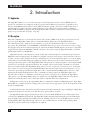
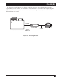
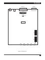
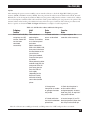
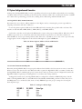
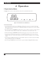
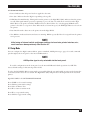
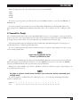
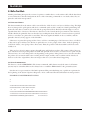
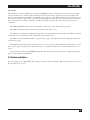
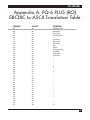
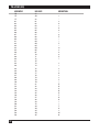
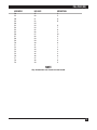
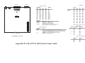
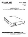
APRIL 1999
PCA35A-R3
PCA35AE-R2
PS035A
PS034E
PQ-6 PLUS (RO)
Receive-only printer interface for IBM® System 3X and AS/400
PQ-6
PWR
STOP
T
STAR
FF
LF
RO)
Plus (
TEST
DATA
OUT
DTR
LINE
SYNC
TEST
CUSTOMER
SUPPORT
INFORMATION
Order toll-free in the U.S. 24 hours, 7 A.M. Monday to midnight Friday: 877-877-BBOX
FREE technical support, 24 hours a day, 7 days a week: Call 724-746-5500 or fax 724-746-0746
Mail order: Black Box Corporation, 1000 Park Drive, Lawrence, PA 15055-1018
Web site: www.blackbox.com • E-mail: [email protected]
PQ-6 PLUS (RO)
FEDERAL COMMUNICATIONS COMMISSION
AND
INDUSTRY CANADA
RADIO FREQUENCY INTERFERENCE STATEMENTS
This equipment generates, uses, and can radiate radio frequency energy and if not installed and used
properly, that is, in strict accordance with the manufacturer’s instructions, may cause interference to radio
communication. It has been tested and found to comply with the limits for a Class A computing device
in accordance with the specifications in Subpart J of Part 15 of FCC rules, which are designed to provide
reasonable protection against such interference when the equipment is operated in a commercial
environment. Operation of this equipment in a residential area is likely to cause interference, in which
case the user at his own expense will be required to take whatever measures may be necessary to correct
the interference.
Changes or modifications not expressly approved by the party responsible for compliance could void the
user’s authority to operate the equipment.
This digital apparatus does not exceed the Class A limits for radio noise emission from digital apparatus set out in the
Radio Interference Regulation of Industry Canada.
Le présent appareil numérique n’émet pas de bruits radioélectriques dépassant les limites applicables aux appareils
numériques de la classe A prescrites dans le Règlement sur le brouillage radioélectrique publié par Industrie Canada.
1
PQ-6 PLUS (RO)
INSTRUCCIONES DE SEGURIDAD (Normas Oficiales Mexicanas Electrical Safety Statement)
1. Todas las instrucciones de seguridad y operación deberán ser leídas antes de que el aparato eléctrico sea operado.
2. Las instrucciones de seguridad y operación deberán ser guardadas para referencia futura.
3. Todas las advertencias en el aparato eléctrico y en sus instrucciones de operación deben ser respetadas.
4. Todas las instrucciones de operación y uso deben ser seguidas.
5. El aparato eléctrico no deberá ser usado cerca del agua—por ejemplo, cerca de la tina de baño, lavabo, sótano
mojado o cerca de una alberca, etc..
6. El aparato eléctrico debe ser usado únicamente con carritos o pedestales que sean recomendados por el fabricante.
7. El aparato eléctrico debe ser montado a la pared o al techo sólo como sea recomendado por el fabricante.
8. Servicio—El usuario no debe intentar dar servicio al equipo eléctrico más allá a lo descrito en las instrucciones de
operación. Todo otro servicio deberá ser referido a personal de servicio calificado.
9. El aparato eléctrico debe ser situado de tal manera que su posición no interfiera su uso. La colocación del aparato
eléctrico sobre una cama, sofá, alfombra o superficie similar puede bloquea la ventilación, no se debe colocar en
libreros o gabinetes que impidan el flujo de aire por los orificios de ventilación.
10. El equipo eléctrico deber ser situado fuera del alcance de fuentes de calor como radiadores, registros de calor,
estufas u otros aparatos (incluyendo amplificadores) que producen calor.
11. El aparato eléctrico deberá ser connectado a una fuente de poder sólo del tipo descrito en el instructivo de
operación, o como se indique en el aparato.
12. Precaución debe ser tomada de tal manera que la tierra fisica y la polarización del equipo no sea eliminada.
13. Los cables de la fuente de poder deben ser guiados de tal manera que no sean pisados ni pellizcados por objetos
colocados sobre o contra ellos, poniendo particular atención a los contactos y receptáculos donde salen del aparato.
14. El equipo eléctrico debe ser limpiado únicamente de acuerdo a las recomendaciones del fabricante.
15. En caso de existir, una antena externa deberá ser localizada lejos de las lineas de energia.
16. El cable de corriente deberá ser desconectado del cuando el equipo no sea usado por un largo periodo de tiempo.
17. Cuidado debe ser tomado de tal manera que objectos liquidos no sean derramados sobre la cubierta u orificios de
ventilación.
18. Servicio por personal calificado deberá ser provisto cuando:
A: El cable de poder o el contacto ha sido dañado; u
B: Objectos han caído o líquido ha sido derramado dentro del aparato; o
C: El aparato ha sido expuesto a la lluvia; o
D: El aparato parece no operar normalmente o muestra un cambio en su desempeño; o
E: El aparato ha sido tirado o su cubierta ha sido dañada.
2
PQ-6 PLUS (RO)
TRADEMARKS
The trademarks mentioned in this manual are the sole property of their owners.
3
PQ-6 PLUS (RO)
CONTENTS
1. Specifications . . . . . . . . . . . . . . . . . . . . . . . . . . . . . . . . . . . . . . . . . . . . . . . . . . . . . . . . . . . . . . . . . . . . . . . . . . . . 5
2. Introduction . . . . . . . . . . . . . . . . . . . . . . . . . . . . . . . . . . . . . . . . . . . . . . . . . . . . . . . . . . . . . . . . . . . . . . . . . . . . . 6
2.1 Application . . . . . . . . . . . . . . . . . . . . . . . . . . . . . . . . . . . . . . . . . . . . . . . . . . . . . . . . . . . . . . . . . . . . . . . . . . . 6
2.2 Description . . . . . . . . . . . . . . . . . . . . . . . . . . . . . . . . . . . . . . . . . . . . . . . . . . . . . . . . . . . . . . . . . . . . . . . . . . . 6
3. Installation . . . . . . . . . . . . . . . . . . . . . . . . . . . . . . . . . . . . . . . . . . . . . . . . . . . . . . . . . . . . . . . . . . . . . . . . . . . . . . 8
3.1 Initial Setup . . . . . . . . . . . . . . . . . . . . . . . . . . . . . . . . . . . . . . . . . . . . . . . . . . . . . . . . . . . . . . . . . . . . . . . . . . 8
3.1.1 Installing a Supported Printer. . . . . . . . . . . . . . . . . . . . . . . . . . . . . . . . . . . . . . . . . . . . . . . . . . . . . . . 8
3.1.2 Power Supply and Grounding of the PQ-6 PLUS (RO) . . . . . . . . . . . . . . . . . . . . . . . . . . . . . . . . . 11
3.1.3 Off-Line Test of PQ-6 (RO) and Printer . . . . . . . . . . . . . . . . . . . . . . . . . . . . . . . . . . . . . . . . . . . . . . 12
3.2 System Configuration and Connection . . . . . . . . . . . . . . . . . . . . . . . . . . . . . . . . . . . . . . . . . . . . . . . . . . . 15
3.2.1 PQ-6 PLUS (RO) Address Selection . . . . . . . . . . . . . . . . . . . . . . . . . . . . . . . . . . . . . . . . . . . . . . . . . 15
3.2.2 System Configuration Reset. . . . . . . . . . . . . . . . . . . . . . . . . . . . . . . . . . . . . . . . . . . . . . . . . . . . . . . . 15
3.2.3 Printer Codes for Pitch and Density . . . . . . . . . . . . . . . . . . . . . . . . . . . . . . . . . . . . . . . . . . . . . . . . . 16
3.3 Placing the PQ-6 in Operation . . . . . . . . . . . . . . . . . . . . . . . . . . . . . . . . . . . . . . . . . . . . . . . . . . . . . . . . . . 16
4. Operation . . . . . . . . . . . . . . . . . . . . . . . . . . . . . . . . . . . . . . . . . . . . . . . . . . . . . . . . . . . . . . . . . . . . . . . . . . . . . . 18
4.1 Operator Controls and Indicators . . . . . . . . . . . . . . . . . . . . . . . . . . . . . . . . . . . . . . . . . . . . . . . . . . . . . . . 18
4.1.1 Function Switches. . . . . . . . . . . . . . . . . . . . . . . . . . . . . . . . . . . . . . . . . . . . . . . . . . . . . . . . . . . . . . . . 18
4.1.2 Indicator Lights . . . . . . . . . . . . . . . . . . . . . . . . . . . . . . . . . . . . . . . . . . . . . . . . . . . . . . . . . . . . . . . . . 19
4.2 Setup Mode. . . . . . . . . . . . . . . . . . . . . . . . . . . . . . . . . . . . . . . . . . . . . . . . . . . . . . . . . . . . . . . . . . . . . . . . . . 19
4.3 Command Pass Through . . . . . . . . . . . . . . . . . . . . . . . . . . . . . . . . . . . . . . . . . . . . . . . . . . . . . . . . . . . . . . . 21
4.4 Buffer Print Mode . . . . . . . . . . . . . . . . . . . . . . . . . . . . . . . . . . . . . . . . . . . . . . . . . . . . . . . . . . . . . . . . . . . . 22
4.4.1 Printout Format . . . . . . . . . . . . . . . . . . . . . . . . . . . . . . . . . . . . . . . . . . . . . . . . . . . . . . . . . . . . . . . . . 22
4.4.2 Data Interpretation . . . . . . . . . . . . . . . . . . . . . . . . . . . . . . . . . . . . . . . . . . . . . . . . . . . . . . . . . . . . . . 22
4.4.3 Notes . . . . . . . . . . . . . . . . . . . . . . . . . . . . . . . . . . . . . . . . . . . . . . . . . . . . . . . . . . . . . . . . . . . . . . . . . . 23
4.5 Functions and Options . . . . . . . . . . . . . . . . . . . . . . . . . . . . . . . . . . . . . . . . . . . . . . . . . . . . . . . . . . . . . . . . 23
Appendix A: PQ-6 PLUS (RO) EBCDIC to ASCII Translation Table. . . . . . . . . . . . . . . . . . . . . . . . . . . . . . . . . 25
Appendix B: Quick Reference Guide for PQ-6 PLUS (RO) . . . . . . . . . . . . . . . . . . . . . . . . . . . . . . . . . . . . . . . 28
4
PQ-6 PLUS (RO)
1. Specifications
Controls—PCA35A-R3, PCA35AE-R2: Reset, Start, Stop, LF, FF, Test
Speed—Serial port, 50 bps to 19.2 kbps
Interface—IBM twinaxial; RS-232/V.24 DCE asynchronous or Centronics type parallel
Connectors—(1) DB15 male with twinax V, (1) DB25 female
Indicators—(5) LEDs: DTR, Line Sync, Power, Test, Data Out
Temperature—Operating: 40 to 100 °F (5 to 42 °C);
Storage: -40 to 140 °F (-40 to 60 °C)
Humidity—0 to 95% noncondensing
MTBF—50,000 hours
Power—PCA35A-R2: 115-VAC, 60-Hz wallmount transformer (part number PS035A);
PCA35AE-R2: 230-VAC, 50-Hz (part number PS034E)
Size—PCA35A-R3, PCA35AE-R2: 2.1"H x 8.8"W x 11.5"D (5.3 x 22.4 x 29.2 cm)
Weight—PCA35A-R3, PCA35AE-R2: 4 lb. (1.9 kg)
5
PQ-6 PLUS (RO)
2. Introduction
2.1 Application
The PQ-6 PLUS (RO) is a “receive-only” microprocessor-based printer interface for the IBM System/34,
System/36, and System/38 computers. It allows a printer with an RS-232 or Centronics compatible port to
interface with IBM twinaxial cable via a male DB15 and twinax “pigtail” cable. Device address and serial or
parallel output are switch selectable, and the baud rate is selectable in 16 settings from 50 to 19,200 bps.
XON/XOFF and DTR are supported by the PQ-6 PLUS (RO) for buffer control. Data format is 7 bits, space
parity, 1 stop or 8 data bits, no parity, 1 stop bit.
2.2 Description
Data and commands are received from the twinax cable serially (1-MHz clock) by the proprietary front-end
processor of the PQ-6 PLUS (RO). Those commands and data addressed to the PQ-6 PLUS (RO) as
determined by the device address selection switches, are passed to the Z-80A microprocessor for further
processing. The Z-80A CPU converts EBCDIC to ASCII and makes the protocol conversions it needs to change
the high-speed synchronous twinax input into an asynchronous RS-232 ASCII output or Centronics compatible
output. You may bypass the EBCDIC to ASCII controller to the printer using the PQ-6 PLUS (RO) commandpassthrough feature (see Section 4.3).
Input data from the controlling host consists of data and command sequences normally interpreted by an
IBM 5256, 5224, and 5225 printer. In addition to printable characters and carriage-control characters (such as
new line, carriage return, and line feed), the controlling host can send command sequences to control output
format. These commands include page width, page length, characters-per-inch, and horizontal and vertical
carriage-positioning sequences. The PQ-6 PLUS (RO) interprets these command sequences and outputs ASCII
characters to perform the appropriate function. For example, when a form length command is received, the
value is stored internally in the PQ-6 PLUS (RO); when it receives a request for a form feed or for an absolute
move to line one of the next page, the PQ-6 PLUS (RO) will cause the paper in the attached printer to eject a
form of the previously specified form length. Since some commands issued to IBM printers cannot be easily
implemented on RS-232 ASCII printers, these commands are interpreted by the PQ-6 PLUS (RO) and
discarded. For example, a command to set the lines per inch to seventy-two is accepted by the PQ-6 PLUS
(RO), but no corresponding ASCII sequence is output, since the PQ-6 PLUS (RO) cannot know in advance
whether the attached printer can accommodate such a command and how to implement it.
As shipped from the factory, the PQ-6 PLUS (RO) is configured to emulate an IBM 5256 printer. If the PQ-6
PLUS (RO) is to emulate the 5224 or 5225 printer, you need to set the appropriate switch on the printed circuit
board (see Section 4.5).
Serial transmission speed is switch-selectable via printed-circuit-board switches, up to 19,200 bps. Output data
is asynchronous with one start bit, seven data bits, space parity, and one stop bit.
The PQ-6 PLUS (RO) supports both software flow control via XON/XOFF characters and hardware flow
control via the DTR RS-232 input lead. The PQ-6 PLUS (RO) will suspend printing whenever the DTR signal
drops and will resume printing when DTR is asserted. Similarly, when it receives an XOFF character (hex 13),
the PQ-6 PLUS (RO) suspends printing; when it receives an XON (hex 11), it will resume printing. Both
methods are always enabled. No configuration is required.
6
PQ-6 PLUS (RO)
The Centronics parallel interface is a 25-pin, parallel byte interface. It has eight lines that carry their
respective binary bits in parallel. The transmission of these data bits is controlled by the computer-supplied
STROBE pulse. Handshaking (flow control) is achieved by asserting or deasserting either the ACKNLG or
BUSY signal from the printer.
Twinaxial
PQ-6 PLUS (RO)
S/3X, AS/400 or remote controller
Serial EBCDIC
data and
commands
(1 MHz bit rate)
ASCII data serial
or parallel
Printer
Figure 2-1. Typical Application.
7
PQ-6 PLUS (RO)
3. Installation
The installation procedure is divided into three sections:
• Section 3.1, Initial Setup, explains how to position the PQ-6 (RO) after unpacking it, plug in the power
supply, and run off-line tests.
• Section 3.2, System Configuration and Connection, covers the considerations for setting up the PQ-6 PLUS
(RO). Items covered include setting the device address and all corresponding physical connections.
• Section 3.3, Placing the PQ-6 PLUS (RO) into Operation, details online testing procedures that you should
implement after completely installing the unit. This section also contains recovery procedures that you can
use if the PQ-6 PLUS (RO) malfunctions.
3.1 Initial Setup
3.1.1 INSTALLING A SUPPORTED PRINTER
CAUTION
Connecting a device to the DB25 connector without properly configuring the P3
jumper inside the box may cause damage to the PQ-6 PLUS (RO) and/or the attached
device.
8
PQ-6 PLUS (RO)
DB25 Female
Power
Serial
Parallel
+5
Ground
1 2 3 4 5 6 7 8
SW2
1 2 3 4 5 6 7 8
EPROM
ON
SW1
Reset
DB15 Male
Test
Data Out
DTR
Line Sync
Power
Figure 3-1. Board Layout.
9
PQ-6 PLUS (RO)
Installing an RS-232 Printer
Connect the 6-pin connector from the power supply to the 6-pin connector on the back of the PQ-6 PLUS
(RO). Remove the top cover of the PQ-6 PLUS (RO). Do not plug it into the AC outlet at this time. Locate
switch SW1 to set the baud rate and port configuration. Select the serial transmission speed (baud rate) for the
PQ-6 PLUS (RO) output port using the four switches labeled Rate 4, Rate 3, Rate 2, and Rate 1 on the printed
circuit board according to Table 3-1.
Table 3-1. Baud Rate.
0=OFF
1=ON
Switch
S5
S6
S7
S8
Baud Rate
OFF
OFF
OFF
OFF
OFF
OFF
OFF
OFF
ON
ON
ON
ON
ON
ON
ON
ON
OFF
OFF
OFF
OFF
ON
ON
ON
ON
OFF
OFF
OFF
OFF
ON
ON
ON
ON
OFF
OFF
ON
ON
OFF
OFF
ON
ON
OFF
OFF
ON
ON
OFF
OFF
ON
ON
OFF
ON
OFF
ON
OFF
ON
OFF
ON
OFF
ON
OFF
ON
OFF
ON
OFF
ON
50
75
110
134.5
150
300
600
1200
1800
2000
2400
3600
4800
7200
9600
19200
Select the port configuration for RS-232 serial operation by setting Opt 3 to the “ON” position.
Place the large internal jumper strip on P3 (P2 on boards with revision levels below C) in the “B-C” position
to select RS-232 output. Make sure that the cable to the PQ-6 PLUS (RO) is wired for DCE and contains wires
for pins 1, 2, 3, 7, and 20, connecting at the PQ-6 PLUS (RO) with a male DB25 connector. The signals are
shown in Table 3-2.
Table 3-2. Signals on the DCE cable.
Pin
Signal Name
Source
1
2
3
7
20
Chassis Ground
Receive Data
Transmit Data
Signal Ground
Data Terminal Ready
—
Printer
PQ-6 PLUS (RO)
—
Printer
Place the supported printer close to the PQ-6 PLUS (RO). Connect the printer RS-232 cable to the DB25
connector on the back panel of the PQ-6 PLUS (RO). Proceed to Section 3.2.3.
10
PQ-6 PLUS (RO)
Installing a Centronics compatible printer
Connect the 6-pin connector from the power supply to the 6-pin connector on the back of the PQ-6 PLUS
(RO). Do not plug it into the AC outlet at this time.
Place the large jumper strip at P3, in the “A-B” position for parallel output.
The Centronics DB25 pinout is a standard DB25 to Centronics cable (Black Box part number EYN600) that
connects the PC to the printer. This cable’s pinning is shown in Table 3-3.
Table 3-3. Centronics to RS-232 Cable Wiring.
Pin No.
Signal
Source
Description
1
2
3
4
5
6
7
8
9
10
Strobe
Data 1
Data 2
Data 3
Data 4
Data 5
Data 6
Data 7
Data 8
Acknlg
PQ-6 PLUS (RO)
PQ-6 PLUS (RO)
PQ-6 PLUS (RO)
PQ-6 PLUS (RO)
PQ-6 PLUS (RO)
PQ-6 PLUS (RO)
PQ-6 PLUS (RO)
PQ-6 PLUS (RO)
PQ-6 PLUS (RO)
Printer
Data strobe pulse to printer.
11
12
13
Busy
Paper End
Select
Printer
Printer
Printer
14
Auto Feed
PQ-6 PLUS (RO)
15
Fault
Printer
16
18, 19,
23, 25
Input
Ground
PQ-6 PLUS (RO)
PQ-6 PLUS (RO)
8 bits of parallel data.
Indicates data received and ready to accept other
data.
Indicates printer cannot receive data.
Indicates out of paper.
Indicates printer is selected and ready to receive
data.
When this signal is low (Jumper J1), the paper is
automatically fed one line after printing. This
signal does not apply to all printers.
Indicates a printer fault condition such as out of
paper.
Clears the printer buffer and initializes the logic.
Logic ground.
Connect the Centronics printer cable to the DB25 connector at the back of the PQ-6 PLUS (RO). Locate
SW1 and set switch option 3 (position 2) to the “OFF” position.
3.1.2 POWER AND GROUNDING OF PQ-6 PLUS (RO)
Plug the power supply into a suitably grounded AC receptacle.
11
PQ-6 PLUS (RO)
3.1.3 OFF-LINE TEST OF PQ-6 PLUS (RO) AND PRINTER
Initial Power On Test
Once both the printer and the PQ-6 PLUS (RO) are plugged into the AC line, turn the printer power switch
“ON” and put it into an “on-line” condition. Make sure the connection between the printer and the PQ-6 PLUS
(RO) is complete. Run the following test to check the power and connections for both devices.
Table 3-4. Initial Test.
12
Initial Test
Device Response
Corrective Action
Plug the PQ-6 (RO) PLUS
power supply into the AC line.
Power and DTR indicators.
Proper response. No corrective
action is necessary.
No response on power or
DTR indicators.
Power supply not plugged into back
connector of the PQ-6 (RO), or no AC
line power, or PQ-6 (RO) power supply
is defective.
DTR indicator blinking.
If configured for serial: The attached
serial device is not providing Data
Terminal Ready (DTR) on Pin 20 of the
PQ-6’s DB25 connector. If configured for
parallel: The attached parallel printer is
not providing the select signal on Pin 13
of the PQ-6’s DB25 connector. Check
that the printer is “ON,” on-line, and the
cable is connected and configured
properly.
PQ-6 PLUS (RO)
Self-Test
After running the power test successfully, you can run the self-test to check the PQ-6 PLUS (RO) program
memory (ROM) and buffer memory (RAM). You can perform the self-test via two different methods: internal
DIP switches or the front-panel test button. Either way, the printer will print the software revision level, address
selected, and printer emulated. The self-test will also send a printed barber-pole test pattern to the printer. The
amount of data in the barber pole is different between the two types of self-tests. The self-test procedures and
device response are shown in Table 3-5. Figure 3-1 illustrates a sample of a self-test printout.
Table 3-5. Self-Test Procedures and Device Responses.
Preliminary
Condition
Initial
Test
Device
Response
Both PQ-6 PLUS (RO)
and printer are “ON”
and the “Power ON”
test has been
conducted
successfully.
Two methods of
1. Printed verification
performing the
occurs as described
self-test: via switches
above.
or via the front-panel
test button
Switch method: Set
SW2-4 ON, SW2-5 ON,
then press and release
the reset button on the
rear of the unit.
Front-panel method:
Press the front-panel
test button.
When performing either
method of self-test, the
front-panel LEDs will
flash once, then the
Data Out LED will
flash rapidly
(depending on the
baud rate if serial)
while data is being
sent to the attached
printer.
2. No response
from printer or random
or garbage characters
are printed.
Corrective
Action
1. Proper response. No
corrective action necessary.
2. Check that the printer is
on-line and the cable is
configured properly. Incorrect
baud rate, parity, or stop bits if
using serial interface.
3. Printed verification
3. Locate Jumper (J1) on PC
has blank line between board and position jumper from
printed lines.
the +5V pin to the center pin.
After the self-test is successfully performed, set SW2 position 5 to “OFF” and press the reset switch.
13
PQ-6 PLUS (RO)
PQ6.PLUS
REV1.41 SOFTWARE
RAM OK
ROM OK
DEVICE ADDRESS 0
Printer = 5256
.<(+|& !$*);^-/,%>? -:#@'="abcdefghi jklmnopqr
-stuvwxyz
{ABCDEFGHI
}JKLMNOPQ
<(+|& !$*);^-/,%>? -:#@'="abcdefghi jklmnopqr
-stuvwxyz
{ABCDEFGHI
}JKLMNOPQ
.<(+|& !$*);^-/ ,%>? -:#@'="abcdefghi jklmnopqr
-stuvwxyz
{ABCDEFGHI
}JKLMNOPQ
<(+|& !$*);^-/ ,%>? -:#@'="abcdefghi jklmnopqr
-stuvwxyz
{ABCDEFGHI
}JKLMNOPQR
<(+|& !$*);^-/ ,%>? -:#@'="abcdefghi jklmnopqr
-stuvwxyz
{ABCDEFGHI
}JKLMNOPQR
.<(+|& !$*);^-/ ,%>? -:#@'="abcdefghi jklmnopqr
-stuvwxyz
{ABCDEFGHI
}JKLMNOPQR
<(+|& !$*);^-/ ,%>? -:#@'="abcdefghi jklmnopqr
-stuvwxyz
{ABCDEFGHI
}JKLMNOPQR
+\& !$*);^-/ ,%>? -:#@'="abcdefghi jklmnopqr
-stuvwxyz
{ABCDEFGHI
}JKLMNOPQR
& !$*);^-/ ,%>? -:#@'="abcdefghi jklmnopqr
-stuvwxyz
{ABCDEFGHI
}JKLMNOPQR
!$*);^-/ ,%>? -:#@'="abcdefghi jklmnopqr
-stuvwxyz
{ABCDEFGHI
}JKLMNOPQR
!$*);^-/ ,%>? -:#@'="abcdefghi jklmnopqr
-stuvwxyz
{ABCDEFGHI
}JKLMNOPQR
!$*);^-/ ,%>? -:#@'="abcdefghi jklmnopqr
-stuvwxyz
{ABCDEFGHI
}JKLMNOPQR
!$*);^-/ ,%>? -:#@'="abcdefghi jklmnopqr
-stuvwxyz
{ABCDEFGHI
}JKLMNOPQR
!$*);^-/ ,%>? -:#@'="abcdefghi jklmnopqr
-stuvwxyz
{ABCDEFGHI
}JKLMNOPQR
*);^-/ ,%>? -:#@'="abcdefghi jklmnopqr
-stuvwxyz
{ABCDEFGHI
}JKLMNOPQR
^-/ ,%>? -:#@'="abcdefghi jklmnopqr
-stuvwxyz
{ABCDEFGHI
}JKLMNOPQR
-/ ,%>? -:#@'="abcdefghi jklmnopqr
-stuvwxyz
{ABCDEFGHI
}JKLMNOPQR
,%>? -:#@'="abcdefghijklmnopqr
-stuvwxyz
{ABCDEFGHI
}JKLMNOPQR
,%>? -:#@'="abcdefghijklmnopqr
-stuvwxyz
{ABCDEFGHI
}JKLMNOPQR
,%>? -:#@'="abcdefghijklmnopqr
-stuvwxyz
{ABCDEFGHI
}JKLMNOPQR
,%>? -:#@'="abcdefghijklmnopqr
-stuvwxyz
{ABCDEFGHI
}JKLMNOPQR
,%>? -:#@'="abcdefghijklmnopqr
-stuvwxyz
{ABCDEFGHI
}JKLMNOPQR
%>? -:#@'="abcdefghijklmnopqr
-stuvwxyz
{ABCDEFGHI
}JKLMNOPQR
>? -:#@'="abcdefghi jklmnopqr
-stuvwxyz
{ABCDEFGHI
}JKLMNOPQR
-:#@'="abcdefghi jklmnopqr
-stuvwxyz
{ABCDEFGHI
}JKLMNOPQR
-:#@'="abcdefghi jklmnopqr
-stuvwxyz
{ABCDEFGHI
}JKLMNOPQR
-:#@'="abcdefghi jklmnopqr
-stuvwxyz
{ABCDEFGHI
}JKLMNOPQR
-:#@'="abcdefghi jklmnopqr
-stuvwxyz
{ABCDEFGHI
}JKLMNOPQR
-:#@'="abcdefghijklmnopqr
-stuvwxyz
{ABCDEFGHI
}JKLMNOPQR
-:#@'="abcdefghijklmnopqr
-stuvwxyz
{ABCDEFGHI
}JKLMNOPQR
-:#@'="abcdefghijklmnopqr
-stuvwxyz
{ABCDEFGHI
}JKLMNOPQ
:#@'="abcdefghijklmnopqr
-stuvwxyz
{ABCDEFGHI
}JKLMNOPQR
@'=" abcdefghijklmnopqr
-stuvwxyz
{ABCDEFGHI
}JKLMNOPQR
=" abcdefghijklmnopqr
-stuvwxyz
{ABCDEFGHI
}JKLMNOPQR
abcdefghijklmnopqr
-stuvwxyz
{ABCDEFGHI
}JKLMNOPQR
bcdefghijklmnopqr
-stuvwxyz
{ABCDEFGHI
}JKLMNOPQR
defghijklmnopqr
-stuvwxyz
{ABCDEFGHI
}JKLMNOPQR
fghijklmnopqr
-stuvwxyz
{ABCDEFGHI
}JKLMNOPQR
hijklmnopqr
-stuvwxyz
{ABCDEFGHI
}JKLMNOPQR
jklmnopqr
-stuvwxyz
{ABCDEFGHI
}JKLMNOPQR
jklmnopqr
-stuvwxyz
{ABCDEFGHI
}JKLMNOPQR
jklmnopqr
-stuvwxyz
{ABCDEFGHI
}JKLMNOPQR
jklmnopqr
-stuvwxyz
{ABCDEFGHI
}JKLMNOPQR
klmnopqr
-stuvwxyz
{ABCDEFGHI
}JKLMNOPQR
Figure 3-1. Sample Self-Test Printout.
14
PQ-6 PLUS (RO)
3.2 System Configuration and Connection
At this point, the PQ-6 PLUS (RO)’s serial or parallel port has been tested off-line and verified to be in working
condition. However, before attaching to the host system, you must consider the overall system layout to establish
the relative device positioning, port selection, cabling, device addressing, and unit identification.
3.2.1 PQ-6 PLUS (RO) ADDRESS SELECTION
Determine the correct device address number for the PQ-6 to use by contacting the person responsible for
assigning workstation and device addresses.
Locate the printer-options/address-selection DIP switches by removing the top half of the enclosure. The
switches are labeled SW2: ADR4 (POS 6), ADR2 (POS 7), and ADR1 (POS 8).
Set the three switches on the right of the DIP switch to arrive at the proper twinax address. When the switch
is OFF, it represents a zero. Conversely, when the switch is ON, it represents a one. The three switches are
labeled ADR 4, 2, and 1, representing a binary value. Therefore, any address, zero to six, can be represented by
an appropriate on-off configuration of the switches. Examples are given in Table 3-6.
Table 3-6. Printer Options/Address Selection DIP Switch.
Decimal
SW6 ADR4
Device Address
SW7 ADR2
SW 8 ADR1
0
1
2
3
4
5
6
7
OFF
OFF
OFF
OFF
ON
ON
ON
ON
OFF
OFF
ON
ON
OFF
OFF
ON
ON
OFF
ON
OFF
ON
OFF
ON
OFF
ON
(ON=ILLEGAL)
3.2.2 SYSTEM CONFIGURATION REQUEST
Physically, the PQ-6 PLUS (RO) is now properly addressed and cabled to the host system or remote controller.
However, before the System 3X or AS/400 system will recognize the PQ-6 PLUS (RO), you must: 1) make sure
the PQ-6 PLUS (RO) is emulating the proper system device and 2) perform a system configuration (unless the
PQ-6 PLUS (RO) is replacing an existing printer or you have auto-config enabled).
As shipped from the factory, the PQ-6 PLUS (RO) is configured to emulate an IBM 5256 printer. On the
inside of the PQ-6 PLUS (RO) are two DIP switches labeled ID1 and ID2 SW2, positions 1 and 2. They select
the IBM printer to be emulated (5256, 5224, or 5225). Table 3-7 gives the proper settings for selecting the
desired printer type.
Table 3-7. Settings for Printer Type.
ID2 SW2-1
ID1 SW2-2
Printer Type
OFF
OFF
ON
ON
OFF
ON
OFF
ON
5256
5224
5225
UNUSED
15
PQ-6 PLUS (RO)
You must configure the system at a console to inform the operating system of the new device port, address,
and unit ID assignments.
NOTE
You don’t have to configure the system if a previously existing 5256, 5224, or 5225
printer was replaced by the PQ-6 PLUS (RO) or if you have auto-config enabled on the
AS/400. If the PQ-6 PLUS (RO) is replacing an existing device, printer ID and device
addressing must remain as established for the removed device.
3.2.3 PRINTER CODES FOR PITCH AND DENSITY
The printer control ode feature in the PQ-6 PLUS (RO) allows the host to control the horizontal pitch (10 and
15 CPI) and vertical pitch (6 and 8 LPI) for certain attached ASCII printers. You can find the list of printers on
page 20.
3.3 Placing the PQ-6 in Operation
When notified that the system operator has completed the system configuration, you can power on the PQ-6
PLUS (RO) (and all other cabled-through devices) using the following procedure:
A. Plug the power supply into the AC line.
B. Place the AC power switch on the attached printer in the “ON” position and place the printer into
“on-line” mode. The DTR indicator should light.
C. The LINE SYNC indicator should light as soon as communications with the host are established. The PQ-6
PLUS (RO) should now be exercised online to verify the operational readiness. Simply execute a print
comand.
MALFUNCTION RECOVERY PROCEDURES
Table 3-8 describes the recovery procedures you can use if the machine malfunctions.
Table 3-8. Recovery Procedures.
Indicator Condition
16
Probable Cause
Recovery Action
PQ-6 PLUS (RO)
No indicator lights
Power supply not plugged
into AC or into PQ-6.
Plug power supply cord into a suitable receptacle.
Line Sync light “OFF”
Printer improperly addressed.
Set correct address on SW2-6, 7, and 8; press
RESET. Check twinax connections.
DTR Flashing
Attached printer OFF, in error
condition, or switches and P2
jumper not in proper position.
Turn on attached printer or check for proper configuration.
Head moving printing
No ribbon.
Defective ribbon.
Install new ribbon.
Install new ribbon.
No printing in test mode. Ribbon out.
Paper out.
Printer AC off.
No DTR or select from printer.
Test message printed
incorrectly.
Install new ribbon.
Install forms.
Turn on printer power.
Check cables and printer power.
Incorrect PQ-6(RO) baud rate. Set correct baud rate via switches on the board.
Bad cable connection to printer. Disconnect power supply, check cable for complete
insertion at both ends. Check for broken wires.
17
PQ-6 PLUS (RO)
4. Operation
4.1 Operator Controls and Indicators
Use Figure 4-1 to locate the controls, indicators, and connectors described in this section.
START
TEST
STOP
LF
FF
TEST
DATA
OUT
DTR
LINE
SYNC
PWR
Figure 4-1. Front-Panel Controls and Indicators.
4.1.1 FUNCTION SWITCHES
• Test: Pressing this switch will cause the TEST light to blink and a test pattern to be printed. If the PQ-6
(RO) cannot detect the attached printer, the TEST light will blink repeatedly. You can clear this condition
by readying the printer.
• Line Feed: Pressing the LINE FEED switch will cause the paper to advance one line for each key you press.
The internal line counter will also be advanced. For continuous line feeds, hold this switch “ON.”
• Form Feed: Pressing the FORM FEED switch will cause the paper to move to the top of the next form.
• Stop: Pressing the STOP switch stops printing on the PQ-6 PLUS (RO) Plus. It also presents “unit not
available” status to the controller. The message “press start on printer Pn” will appear on the controlling
console.
• Start: Pressing the START switch will present “unit available” status to the controller and clear the STOP
message. Printing will resume on the PQ-6 Plus.
• Reset: Pressing the RESET switch (located on the rear panel) initializes all PQ-6 PLUS (RO) hardware.
18
PQ-6 PLUS (RO)
4.1.2 INDICATOR LIGHTS
• Power: Indicates that AC power has been applied to the unit.
• Line Sync: Indicates that the PQ-6 is responding to host polls.
• DTR (Data Terminal Ready): This signal from the printer to the PQ-6 PLUS (RO) indicates that the printer
is ready. This signal must be present for printing to proceed. You can enable flow control from the PQ-6
PLUS (RO) to the printer via XON/XOFF characters (Hex 11/Hex 13) or by dropping DTR when the
printer is not able to accept more data. When used as a Centronics port, the DTR light indicates select from
the printer.
• Data Out: Shows the data sent to the printer from the PQ-6 PLUS.
• Test: Blinks to indicates that internal tests are running. Blinks repeatedly if the select signal from the printer
is not present.
NOTE
Initial setup of internal switch and jumper settings for baud rate, printer interface, etc.,
must have been done previously. See Section 3.1.
4.2 Setup Mode
You can configure the PQ-6’s twinax address, printer emulated, ASCII printer type, page select and command
pass-through by the front panel or the internal DIP switches.
NOTE
ASCII printer type is only selectable via the front panel.
To enable configuration via the front panel, set the internal DIP switch bank 2 position 4 to OFF. The
factory-default setting for this switch position is ON.
To place the PQ-6 PLUS (RO) in setup mode, press and hold in the test switch while pressing and releasing the
reset switch, then release the test switch. The PQ-6 PLUS (RO) will print the following menu on the attached
printer:
PQ-6 PLUS REV. 1.41 SOFTWARE SETUP MODE
Press START to select switch settings
Press STOP to print switch settings
Press LF to do Printer Test
Press FF to return to twinax mode
Press FF to accept switch setting
Press STOP to toggle switch setting
19
PQ-6 PLUS (RO)
DEVICE ADDRESS 0
DEVICE ADDRESS 7
DEVICE ADDRESS 6
DEVICE ADDRESS 5
DEVICE ADDRESS 4
DEVICE ADDRESS 3
DEVICE ADDRESS 2
DEVICE ADDRESS 1
DEVICE ADDRESS 0
Printer=5224
Printer=5225
Page Eject is Form Feeds
Page Eject is Line Feeds
Command Pass Thru is Disabled
Command Pass Thru is Enabled
Current printer attached is Generic 3400h
Current printer attached is IBM Proprinter
Current printer attached is Okidata 2410
Current printer attached is Okidata 83/84
Current printer attached is MX-80
Current printer attached is T.I. 810/820
Current printer attached is NEC SpWr 3500
Current printer attached is FX-80
Press FF to save configuration
Press STOP to cancel configuration
SELECTING SWITCH SETTINGS
This mode lets you change the initial switch settings using the front panel instead of removing the top cover of
the PQ-6 PLUS.
Follow the instructions on the printed menu to select the different switch selections.
Upon exiting this mode, the switch selections will be stored in nonvolatile memory; the PQ-6 will retain
them until you change them using the front panel. On the next power-up, the PQ-6 PLUS will be configured to
the last stored setup. If no previous configuration was stored, the PQ-6 PLUS will default to the current switch
settings on the PC board, and the printer type will be Generic 3400h.
20
PQ-6 PLUS (RO)
When selecting printer type, the following data is used by the PQ-6 PLUS:
6 LPI
8 LPI
10 CPI
15 CPI
If you select a generic printer, the data used is located at 3400H and must be entered in the EPROM (see
Section 3.3.3).
To cancel a print job sent from the host, press and hold the STOP button on the PQ-6 Plus (RO) front
panel, and press the START button simultaneously. This sends a cancel request to the host, ending the print
job.
4.3 Command Pass-Through
The command pass-through feature in the PQ-6 PLUS (RO) lets you (or a programmer) control an attached
printer so that you can use special functions or features of the printer. It’s required because the IBM System 3X
operating software will not allow codes below Hex 40 to be transmitted on the twinax cable.
The method will transmit any 8-bit binary value from Hex 00 to Hex FF. The PQ-6 does not interpret or
translate data when in command pass-through mode.
To enter command pass-through mode, send the two-character sequence ampersand percent (&%) as part
of the normal printable data.
NOTE
Ampersand (&)=EBCDIC 50 Hex
Percent (%)=EBCDIC 6C Hex
After it enters command pass through mode, the PQ-6 PLUS (RO) takes characters from its internal print
buffer and outputs a single 8-bit binary value for every two EBCDIC characters it receives. The two EBCDIC
characters should embody the Hex representation of a legal 8-bit value.
Example: To send an ASCII escape character (1B Hex), send the two-character sequence ampersand percent
as a terminating character pair.
NOTE
No gaps or spaces should occur between any characters during command pass
through mode.
To send the sequence of ASCII characters “ABC (space) 1 2 3,” the following command pass-through
sequence would be sent:
EBCDIC - & % 4 1 4 2 4 3 2 0 3 1 3 2 3 3 & %
Hex
- 50 6C F4 F1 F4 F2 F4 F3 F2 F0 F3 F1 F3 F2 F3 F3 50 6C
21
PQ-6 PLUS (RO)
4.4 Buffer Print Mode
A buffer print listing interprets the actions of a printer or similar device on the twinax cable. All the data that is
received is listed as a hexadecimal printout. None of the formatting commands are executed; rather, they are
printed to aid in the interpretation.
4.4.1 PRINTOUT FORMAT
The data transmitted on the twinax cable is sent in blocks. A block can be one byte to 256 bytes long. The PQ-6
does not interpret the poll requests and device commands (such as device status) in a buffer print listing, but
prints all of the data received in each of the blocks, grouped in its block. Each byte that the PQ-6 receives is
expanded into three characters. The first two characters are the hexadecimal representation of the data byte,
and the third is the printable character that the byte would print if any. The three characters that are printed
for the received byte are printed in a vertical line. The most significant nibble on the second line, and the
printable character, if any, appear on the third line.
Characters are printed in groups of three lines, each line containing up to 128 characters. Since each block
of data can be up to 256 bytes, the blocks are printed in one or two groups of three lines. At the beginning of
each block of data, a new group of three lines starts. Thus, the position of the data within each block can be
readily seen.
Take care here if you’re using a printer that will print only 80 character lines. The groups of three lines are
up to 128 characters long. If the printer used will only print 80 character lines, or has been set to print only 80
character lines, one of two things will occur depending on the printer. If the printer is set to not auto-new-line,
the printer does an auto-new-line after reaching its line length, and the end of each line will be interlaced
between each of the original lines. You can interpret this once you realize what is happening.
4.4.2 DATA INTERPRETATION
The data is received in IBM EBCDIC. The format commands, while almost exactly the same for all twinax
systems, may be somewhat different. It is always best to consult the IBM manual for the particular system.
Listed next is a representation of the buffer printout. This particular listing was copied from a printout for
the beginning of the System 34 printer diagnostic. A few comments follow that will assist in its interpretation.
EXAMPLE OF A BUFFER PRINT LISTING
0
C
2C002D02002D0802C082C042C040
B62CB2490AB1310B124B222B8201
F
K
J a A d B
H
CCCCCCCCCDDDDDDDDDEEEEEEEE44444FFFFFFFFFF
12345678912345678923456789000000123456789
ABCDEFGHIJKLMNOPQRSTUVWXYZ
0123456789
22
PQ-6 PLUS (RO)
4.4.3 NOTES
The first block contains a single byte (a hex 0C). In EBCDIC, that’s a formfeed. Note that it is not a printing
character and the space under the 0C is blank. The next block of data contains 28 bytes. It starts with a 2B,
which is a format command (similar to an ASCII escape sequence). The 2BC6 denotes set line density, 02 says 2
bytes after the 2BC6 are part of the command. The 0C designates 6 lines per inch. The C6 has an “F” under it.
If it occurred not in a format command, it would be printable “F,” but it does not print since it is part of a
command.
The 2B D2 04 29 00 0A is the format command to set the printer into 10 characters per inch.
The 2B D1 03 81 00 sets the printer into the international character set.
The 2B C1 is for setting the maximum print position. 02 again states that 2 bytes follow the 2BC1 command,
and 84 is hex for 132. Thus, it sets the maximum print position to 132.
The 2B C2 sets the maximum number of print lines per page. 02 42 specifies two following bytes and sets it
to 66 lines per page.
The 2B C8 states what the printer will do when it receives a character that is undefined. This sequence of 02
bytes sets the printer to print a hex 40 (which is a space), and the 01 indicates to continue without any error
action.
The next block of data is actual EBCDIC printable data (the first data that the printer actually prints). This
pattern is the alphabet and numbers.
4.5 Functions and Options
For easy setup, the new PQ-6 PLUS (RO) single-port device features slide-type DIP switches that you can access
by removing the top cover.
23
PQ-6 PLUS (RO)
SWITCH DEFINITION TABLES
Table 4-1. Option Switch SW1 Baud Rate Selection (0=OFF, 1=ON).
Switch Bank 1
5
6
7
8
OFF
OFF
OFF
OFF
OFF
OFF
OFF
OFF
ON
ON
ON
ON
ON
ON
ON
ON
OFF
OFF
ON
ON
OFF
OFF
ON
ON
OFF
OFF
ON
ON
OFF
OFF
ON
ON
OFF
ON
OFF
ON
OFF
ON
OFF
ON
OFF
ON
OFF
ON
OFF
ON
OFF
ON
OFF
OFF
OFF
OFF
ON
ON
ON
ON
OFF
OFF
OFF
OFF
ON
ON
ON
ON
Baud Rate
50
75
110
134.5
150
300
600
1200
1800
2000
2400
3600
4800
7200
9600
19200
Option Select
1 (OPT4)
2 (OPT3)
3 (OPT2)
4 (OPT1)
ON=Buffer print mode.
ON=Serial
OFF=Parallel
ON=Enable Command Passthrough
OFF=Disable Command Passthrough
OFF=Use FF (Form Feed) character for page eject.
ON=Use Multiple Line Feed for page eject.
Table 4-2. Option Switch SW2.
Switch Bank 2 Position
Function
1, 2
3
Printer type select (00=5256, 01=5224, 10=5225, 11=illegal)
Parallel Print option (OFF=PQ-6 responds to the busy and acknowledge
signals from the printer. ON=PQ-6 responds to the busy signal only. This
setting increases the data transfer rate to the printer.)
Configuration option (ON=DIP switch, OFF=Front panel)
Self-Test
Address select (0-6) 0=OFF, 1=ON
4
5
6, 7, 8
When the auto-feed jumper is installed in the ground position, the paper is automatically fed one line after
printing. This signal does not apply to all printers.
Jumper (J1) applies either +5 or ground or pin 14 of the Centronics printer connector.
24
PQ-6 PLUS (RO)
Appendix A: PQ-6 PLUS (RO)
EBCDIC to ASCII Translation Table
HEX EBCDIC
HEX ASCII
DESCRIPTION
05
0B
0C
00
0F
15
16
25
2F
40
46
47
48
49
4B
4C
4D
4E
4F
50
5A
5B
5C
5D
5E
5F
60
61
6A
6B
6C
6D
6E
6F
79
7A
7B
7C
09
08
0C
00
20
0A
08
0A
07
20
20
20
20
20
2E
3C
28
2B
7C
26
21
24
2A
29
3B
5E
2D
2F
7C
2C
25
5F
3E
3F
60
3A
23
40
Horizontal Tab
Backspace
Form Feed
Carriage Return
|
Line Feed
Backspace
Line Feed
Bel
Space
Carriage Return
Line Feed
Form Feed
Line Feed
.
<
[
|
&
$
*
]
;
^
/
|
,
%
_
>
?
:
=
@
25
PQ-6 PLUS (RO)
26
HEX EBCDIC
HEX ASCII
DESCRIPTION
7D
7E
7F
81
82
83
84
85
86
87
88
89
91
92
93
94
95
96
97
98
99
A1
A2
A3
A4
A5
A6
A7
A8
A9
C0
C1
C2
C3
C4
C5
C6
C7
C8
C9
D0
D1
D2
D3
D4
D5
27
3D
22
61
62
63
64
65
66
67
68
69
6A
6B
6C
6D
6E
6F
70
71
72
7E
73
74
75
76
77
78
79
7A
7B
41
42
43
44
45
46
47
48
49
7P
4A
4B
4C
4D
4E
'
=
"
a
b
c
d
e
f
g
h
i
j
k
l
m
n
o
p
q
r
s
t
u
v
w
x
y
z
[
A
B
C
D
E
F
G
H
I
]
J
K
L
M
N
PQ-6 PLUS (RO)
HEX EBCDIC
HEX ASCII
DESCRIPTION
D6
D7
D8
E9
E0
E2
E3
E4
E5
E6
E7
E8
E9
F0
F1
F2
F3
F4
F5
F6
F7
F8
F9
4F
50
51
52
5C
53
54
55
56
57
58
59
5A
30
31
32
33
34
35
36
37
38
39
O
P
Q
R
S
T
U
V
W
X
Y
Z
0
1
2
3
4
5
6
7
8
9
NOTE
Any characters not shown are not used.
27
DB25 Female
DB15 Male
Baud Rate.
Option Switch SW1.
Power
Parallel
Ground
+5
EPROM
Switch Bank 1
5
6
7
8
OFF
OFF
OFF
OFF
OFF
OFF
OFF
OFF
ON
ON
ON
ON
ON
ON
ON
ON
OFF
OFF
ON
ON
OFF
OFF
ON
ON
OFF
OFF
ON
ON
OFF
OFF
ON
ON
OFF
ON
OFF
ON
OFF
ON
OFF
ON
OFF
ON
OFF
ON
OFF
ON
OFF
ON
OFF
OFF
OFF
OFF
ON
ON
ON
ON
OFF
OFF
OFF
OFF
ON
ON
ON
ON
Baud Rate
50
75
110
134.5
150
300
600
1200
1800
2000
2400
3600
4800
7200
9600
19200
0=OFF
1=ON
12 3 4 5678
1 (OPT4)
2 (OPT3)
3 (OPT2)
4 (OPT1)
Test
Data Out
DTR
Line Sync
Power
ON=Buffer print mode.
ON=Serial
OFF=Parallel
ON=Enable Command Pass Thru
OFF=Disable Command Pass Thru
OFF=Use FF (Form Feed) character for page eject.
ON=Use Multiple Line Feed for page eject.
Option Switch SW2.
Switch Bank 2
Position
Function
1, 2
3
Printer type select (00=5256, 01=5224, 10=5225, 11=illegal)
Parallel Print option (OFF=PQ-6 responds to the busy and acknowledge
signals from the printer. ON=PQ-6 responds to the busy signal only. This
setting increases the data transfer rate to the printer.)
Configuration option (ON=DIP switch, OFF=Front panel)
Self-Test
Address select (0-6) 0=OFF, 1=ON
ON
12 3 4 5678
SW2
Option Select
SW1
Reset
Serial
4
5
6, 7, 8
Switch
S5
S6
S7
S8
OFF
OFF
OFF
OFF
OFF
OFF
OFF
OFF
ON
ON
ON
ON
ON
ON
ON
ON
OFF
OFF
OFF
OFF
ON
ON
ON
ON
OFF
OFF
OFF
OFF
ON
ON
ON
ON
OFF
OFF
ON
ON
OFF
OFF
ON
ON
OFF
OFF
ON
ON
OFF
OFF
ON
ON
OFF
ON
OFF
ON
OFF
ON
OFF
ON
OFF
ON
OFF
ON
OFF
ON
OFF
ON
50
75
110
134.5
150
300
600
1200
1800
2000
2400
3600
4800
7200
9600
19200
Printer Options/Address Selection DIP Switch.
Device Address
Decimal SW6 ADR4
SW7 ADR2
SW 8 ADR1
0
1
2
3
4
5
6
7
OFF
ON
OFF
ON
OFF
ON
OFF
ON
OFF
OFF
OFF
OFF
ON
ON
ON
ON
PQ-6 (RO) Board Layout.
Appendix B: PQ-6 PLUS (RO) Quick Setup Guide
Baud Rate
OFF
OFF
ON
ON
OFF
OFF
ON
ON
(ON=ILLEGAL)
Settings for Printer Type.
ID2 SW2-1
ID1 SW2-2
Printer Type
OFF
OFF
ON
ON
OFF
ON
OFF
ON
5256
5224
5225
UNUSED
© Copyright 1999. Black Box Corporation. All rights reserved.
1000 Park Drive
•
Lawrence, PA 15055-1018
•
724-746-5500
•
Fax 724-746-0746