1
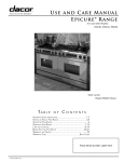
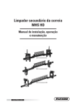
Installation Instructions
Epicure ® Ranges
For use with models:
Part No. 65089 Rev. J
EGR30, ERD30, ERD60
Table of Contents
Important Safety Instructions...................................................... 1
General Safety Precautions......................................................... 1
Product Specifications.................................................................3
Product Dimensions.....................................................................3
Gas Supply Requirements........................................................... 3
Electrical Power Supply Requirements.......................................3
Planning the Installation............................................................... 4
Cabinet and Countertop Preparation...........................................4
Installation Instructions................................................................6
Verifying Package Contents........................................................ 6
Installing the Anti-Tip Bracket...................................................... 6
Door Removal..............................................................................6
Utility Locations............................................................................7
Electrical Connection...................................................................8
Gas Connection...........................................................................9
Installing the Range..................................................................... 9
Installing the Burner Components.............................................10
Re-Installing the Oven Doors....................................................10
Verifying Proper Operation........................................................ 10
Notes.......................................................................................11-13
IMPORTANT:
•
Installer: In the interest of safety and to minimize problems, read these installation instructions completely and carefully before you
begin the installation process. Leave these installation instructions with the customer.
•
Customer: Keep these installation instructions for future reference and the local electrical inspector’s use.
Customer Service Information
If the unit requires service or you have questions or problems with installation, contact your Dacor
Service Team.
®
dealer or the Dacor Customer
Dacor Customer Service Team
(800) 793-0093 (U.S.A. and Canada)
Monday — Friday 6:00 a.m. to 5:00 p.m. Pacific Time
Web site: www.Dacor.com
Be sure to have the model and serial number available when you call. The model and serial number are on the product data label
attached to the appliance. Open the oven door and remove the inlet air cooling grill for access to the label.
All specifications subject to change without notice. Dacor assumes no liability for changes to specifications.
© 2006 Dacor, all rights reserved.
Important Safety Instructions
Safety Symbols and Labels
Important Information About Safety
Instructions
DANGER
The Important Safety Instructions and warnings in these
instructions are not meant to cover all possible problems and
conditions that can occur. Use common sense and caution when
installing, maintaining or operating this or any other appliance.
Immediate hazards that WILL result in severe personal injury or
death.
Always contact Dacor about problems or conditions you do not
understand.
Hazards or unsafe practices that COULD result in severe
personal injury or death.
READ AND SAVE THESE
INSTRUCTIONS
WARNING
CAUTION
Hazards or unsafe practices that COULD result in minor
personal injury or property damage.
DANGER
WARNING
IMPORTANT: If you smell gas:
•
Do not use or light any appliance.
•
Do not touch any electrical switch or use any electrical
devices, including the telephone, in your building.
•
From a neighbors phone, immediately call the gas
supplier. Follow the gas supplier’s instructions.
•
If you cannot contact the gas supplier, call the fire
department.
WARNING – NEVER use this appliance as a space heater
to heat or warm the room. Doing so may result in carbon
monoxide poisoning and overheating of the appliance.
WARNING
IMPORTANT: Do not store or use combustible, flammable or
explosive vapors and liquids (such as gasoline) inside or in
the vicinity of this or any other appliance. Also keep items that
could explode, such as aerosol cans, away from the burners
and the oven. Do not store flammable or explosive materials
in adjacent cabinets or areas.
WARNING – NEVER cover any slots, holes or passages in
the oven bottom or cover an entire rack with materials such as
aluminum foil. Doing so blocks air flow through the oven and
may cause carbon monoxide poisoning. Aluminum foil linings
may also trap heat, causing a fire hazard.
CALIFORNIA
PROPOSITION 65 WARNING
The burning of gas cooking fuel generates some by-products
that are on the list of substances which are known by the State
of California to cause cancer or reproductive harm. California
law requires businesses to warn customers of potential
exposure to such substances. To minimize exposure to these
substances, always operate this unit according to the use
and care manual, ensuring you provide good ventilation when
cooking with gas.
General Safety Precautions
To reduce the risk of fire, explosion, electric shock, serious injury or death when installing or using this appliance, follow
basic safety precautions, including the following:
WARNING
•
Read the accompanying use and care manual completely before operating this appliance.
•
Keep packaging materials away from children. Plastic sheets and bags can cause suffocation.
•
If you receive a damaged product, immediately contact your dealer or builder. Do not install or use a damaged appliance.
•
This range must be properly installed and grounded by a qualified installer according to these installation instructions prior to
use. The installer should show the customer the location of the gas shut off valve and the fuse or junction box so that they know
where and how to turn off the gas supply and electric power to the range.
•
Do not operate the range without the backguard or raised vent in place if the back wall is made of combustible materials. A fire
may result.
•
Do not install, repair or replace any part of the range unless specifically recommended in the literature accompanying it. A
qualified service technician should perform all other service.
•
Do not connect this range to the gas supply without the supplied gas pressure regulator installed.
1
Important Safety Instructions
General Safety Precautions (cont.)
WARNING
•
Before performing any type of service or installation, make sure that the gas supply and electric power to the range are off.
•
NEVER block or cover any slots, holes or passages anywhere inside the oven or on the outside of the range or cover an
oven rack with materials such as aluminum foil. Doing so blocks airflow through the oven and cooktop and may cause carbon
monoxide poisoning or fire.
•
Only use the range for cooking tasks expected of a home appliance as outlined in the literature accompanying it. This range is
not intended for commercial use.
•
DO NOT TOUCH THE SURFACES OF THE OVEN OR COOKTOP DURING OR IMMEDIATELY AFTER USE.
•
Do not climb on any part of the appliance.
•
Do not leave children alone or unattended in the area around the range. Do not allow children to play with the controls, pull on
the handle, or touch other parts of the range.
•
Do not store items of interest to children on top of or above the range. Children could be burned or injured while climbing on the
appliance.
•
Do not attempt to use this appliance in the event of a power failure.
•
Do not tamper with the controls. Do not adjust or alter any part of the range unless specifically instructed to do so in these
instructions.
•
To prevent the unit from tipping forward and to provide a stable installation, the unit must be secured in place with the anti-tip
device as specified in these instructions.
•
Clean the cooktop thoroughly before operating it for the first time.
•
Keep flammable items, such as paper, cardboard, plastic and cloth away from the burners and other hot surfaces. Do not place
such items in the oven. Do not allow pot holders to touch hot surfaces or gas burners.
•
Do not wear loose or hanging apparel while using the range. Do not allow clothing to come into contact with the interior of the
oven or the cooktop and surrounding areas during and immediately after use.
•
To avoid a fire hazard, do not hang flammable or heat sensitive objects over the range.
•
If the range is near a window, do not use long curtains as window treatment. The curtains could blow over the cooktop and
create a fire hazard.
•
Do not use the oven for storage.
•
Do not touch the burner assembly, grates or surrounding surfaces (including the backguard) or the interior surfaces of the oven
during use. After use, make sure these surfaces have had sufficient time to cool before touching them.
•
Do not touch the outside surfaces of the range during the self-clean cycle. They will be hot. Venting from the oven may cause the
cooktop and backguard to become hot.
•
Make sure that all the cooktop parts are dry before lighting a burner.
•
Turn the knobs to the OFF position prior to removing them from the valve stems.
•
The cooktop should never be operated without the knobs and trim rings in place.
•
For your safety, do not use the oven to cook without the convection filter(s) installed. When the filter is not installed, the spinning
fan blades at the back of the oven are exposed.
•
Non-stick coatings, when heated, can be harmful to birds. Remove birds to a separate, well-ventilated room during cooking.
caution
•
To prevent damage, remove the meat probe from the oven when it is not being used.
•
Do not line the oven with aluminum foil or other materials. These items can melt or burn up during self-cleaning and cause
permanent damage to the oven.
•
Do not leave metal objects, such as aluminum foil, the meat probe, cookie sheets, etc. on the bottom of the oven. Objects left on
the bottom of the oven could damage the bake element. In addition, the objects themselves could be damaged.
•
Do not cover bake or broil elements in the top and bottom of the oven with cookie sheets, aluminum foil, pots, pans, etc.
Covering them could cause the heating elements to over-heat, damaging the oven.
•
Always ensure that the light fixture lens covers are in place when using the oven. The lens covers protect the light bulbs from
breakage caused by high oven temperatures or mechanical shock.
2
Product Specifications
Product Dimensions
Gas Supply Requirements
NOTE: For ERD series models, all front-to-back depth dimensions
are reduced by 1” (25mm) when the backguard and the full side
panels are removed.
Check your local building codes for the proper method of
installation. In the absence of local codes, this appliance should
be installed in accordance with the National Fuel Gas Code ANSI
Z223.1. Be certain that the appliance being installed is correct for
the gas service being provided. Refer to the data label located
behind the inlet air cooling grill, or the table below, for gas supply
requirements. Open the oven door and remove the inlet air
cooling grill for access to the data label.
28 1/2" (724mm)
Handle
27" (686mm)
Front Edge of Bullnose
26" (660mm)
Face of Control Panel/Oven Door
24 3/8" (619mm)
Rear of Control Panel/Oven Door
1 9/16"
(40mm)
6” (152mm) Backguard
When Backguard and
Side Panels are
removed, the overall
depth decreases
by 1" (25mm)
Electrical Power Supply Requirements
It is the owner’s responsibility to ensure that the electrical
connection of this appliance is performed by a qualified
electrician. The electrical installation, including minimum supply
wire size and grounding, must be in accordance with the National
Electric code ANSI/NFPA 70-1993* (or latest revision) and local
codes and ordinances.
35 3/4"
(908mm)
to
37”
(940mm)
*A copy of this standard may be obtained from:
National Fire Protection Association
1 Batterymarch Park
Quincy, Massachusetts 02269-9101
Finished Side Panel
The correct voltage, frequency and amperage must be supplied to
the appliance from a separate, grounded, circuit that is protected
by a properly sized circuit breaker or time delay fuse. Refer to the
data label, or the table below, for electrical requirements.
Accessory 3” (76mm) Side Panels
(Dacor Model No. AESP03)
EGR30, ERD30, ERD60 Overall Dimensions - Side View
Model No.
EGR30
EGR30LP
ERD30
ERD30LP
ERD60
ERD60LP
Electrical
Circuit Required
Total
Connected
Load
120 Vac 60Hz,
15 Amp.
0.75 kW
(6.2 Amp.)
240 Vac, 60Hz,
30 Amp.
4.2 kW
(18 Amp.)
240 Vac, 60Hz,
30 Amp. X 2*
4.1 kW X 2*
(21 Amp X 2)
Gas
Type
Manifold
Pressure
Min. Gas Supply
Pressure
Natural
5” Water
Column
6” Water Column
LP
10” Water
Column
11” Water Column
Natural
5” Water
Column
6” Water Column
LP
10” Water
Column
11” Water Column
Natural
5” Water
Column
6” Water Column
LP
10” Water
Column
11” Water Column
Gas and Electrical Supply Requirements
* For model ERD60, two separate dedicated circuits are required, one for the left, and one for the right
side of the range.
The above information is for reference only. If the information above differs from the information on the
product data label on the appliance, use the information on the label.
3
Planning the Installation
WARNING
•
Both the gas supply piping and shut-off valve, and the
electrical junction box/receptacle must be located so they do
not interfere with the range when it is installed. In addition,
the junction box must be located so the range can be
removed for service when the conduit supplied with the unit
is attached to the junction box. Do not lengthen the conduit or
wiring provided with the range.
•
All dimensions shown are based on standard American
cabinets 36 inches (914mm) high at the finished countertop
by 24 inches (610mm) deep, with a 25 inch (635mm) overall
countertop depth. All minimum clearances shown MUST be
maintained.
•
Carefully check the location where the range is to be
installed. For best performance, the range should be placed
away from drafts that may be caused by doors, windows and
HVAC outlets.
•
If cabinet storage space is to be provided directly above the
range, the risk of personal injury may be reduced by installing
a ventilating hood that projects horizontally a minimum of 5
inches beyond the face of the cabinets.
•
The range may be installed flush to the rear wall. Dacor
highly recommends installing a non-combustible material on
the rear wall above the range and up to the vent hood. It is
not necessary to install non-combustible materials behind the
range below the countertop height.
IMPORTANT: Observe all governing codes and ordinances
during planning and installation. Contact your local building
department for further information.
Cabinet and Countertop Preparation
•
•
The shaded areas shown in the illustrations below show the
recommended location of the gas stub and the electrical
junction box/receptacle in the lower left corner of the adjacent
right cabinet. For replacement purposes, the location of the
existing utilities may be utilized provided that they do not
interfere with the sides or rear of the range. If installing the
gas valve behind the range, verify that doing so is permitted
by local building codes.
A manual shut valve must be installed in the gas piping,
external to the appliance, for the purpose of turning on or
shutting off gas to the appliance. Plan the location of the
range and the gas supply to allow access to the valve when
the unit is installed. Access to the remote circuit breaker
panel/fuse box with the range in place must also be allowed
for in the installation. Any openings in the wall behind the
appliance and in the floor under the appliance must be
sealed.
B
Model
Number
ERD30
EGR30
ERD60
Non-Combustible
surface along
back wall
30” (762mm)
min.*
**
A
Suggested
location of
utilities
* Vertical to combustible surface
** Cabinet depth is at discretion of customer
but cabinet face MUST NOT protrude further
than rear of front panel, see product dimesions
Cutout Dimensions
4
“A”
“B”
30 1/16”
(764mm)
36” (914mm)
Recommended
30” (762mm) Minimum
60 1/8”
(1572mm)
66” (1676mm)
Recommended
60” (1542mm) Minimum
Installation Specifications
3/4" (19mm)
Max. backsplash
1/4" (6mm)
Min. flat ledge
Rear wall
Rear wall
Vertical
non-combustible
surface
23 3/16"
(589mm)
Variable
13/16" - 3 13/16"
(21 - 97mm)
13/16" (21mm)
13/32"
(10mm)
29 1/4" (743mm)
30 1/16" (764mm)
ERD/EGR30 Slide-In, Self-Rimming
Installation with Side Panels and
Backguard Removed
Top View
Vertical
non-combustible
surface rear wall
20 3/16"
(513mm)
Vertical
non-combustible
surface
27 7/8" (708mm)
27 13/16"
(706mm)
29 1/4" (743mm)
30 1/16" (764mm)
13/32"
(10mm)
ERD/EGR30 Slide-In, Self-Rimming Installation using
3” Side Panels (Model No. AESP03),
Backguard Removed.
Top View
Backsplash
thicker than
3/4" (19mm)
1/4" (6mm)
Min. flat ledge
2 13/16"
(71mm)
Adjust for backsplash
over 3/4" thick
from 13/16" to 3 13/16"
(21 - 97mm)
13/32" (10mm)
29 1/4" (743mm)
30 1/16" (764mm)
Countertop overhangs cabinet
6" (152mm) Min.
to combustible side
walls above the range
(both sides)
ERV30 with ERD30 Slide-In, Self-Rimming Installation using 3” Side Panels (Model No. AESP03), Backguard Removed.
Top View
Vertical
non-combustible
surface rear wall
27 7/8" (708mm)
3/4" (19mm)
Max. backsplash
27 13/16"
(706mm)
23 3/16"
(589mm)
1/4" (6mm)
Min. flat ledge
2 13/16"
(71mm)
13/16" (21mm)
13/32" (10mm)
29 1/4" (743mm)
30 1/16" (764mm)
Countertop overhangs cabinet
6" (152mm) Min.
to combustible side
walls above the range
(both sides)
ERV30 with ERD30 Slide-In, Self-Rimming Installation with Side Panels and Backguard Removed - Top View
5
Installation Instructions
WARNING
•
Observe all governing codes and ordinances during
planning and installation. Contact your local building
department for further information.
•
If the gas or electric service provided does not meet the
product specifications, do not proceed with the installation.
Call the selling dealer, the gas supplier or a licensed
electrician.
•
This appliance must be installed by a licensed plumber
or gas fitter when installed within the Commonwealth of
Massachusetts.
Verifying the Package Contents
Door Removal
To make the range easier to move during installation, remove the
door(s) before installation.
WARNING
•
Do not attempt to disengage the hinge catches with the
door removed from the oven. The hinge springs could
release causing personal injury.
•
Do not lift or carry the oven door(s) by the door handle.
1. Open the door to its fully opened position.
2. Rotate the catch over the retaining arm on each hinge.
Hinge Catch
Verify that all required components have been provided. If
any item is missing or damaged, please contact your dealer
immediately. Do not install a damaged or incomplete appliance.
•
Use and care manual
•
Ignitor cleaning kit
•
Broiler pan/grill
•
Anti-tip bracket (selected models)
•
Grate/burner cap packs
•
Griddle
•
Burner rings
•
Wok ring
•
Simmer plate
•
Spatula
•
Stainless steel cleaner
•
Lens pry stick (selected models)
To remove door
,
rotate catch up.
3. Lift the oven door to about a 30 degree angle from the
horizontal position.
Installing the Anti-Tip Bracket
Hinge Catch
(Models ERD30 and EGR30 Only)
30” ranges require an anti-tip device. Before installing the range,
you must locate the anti-tip bracket in the product packaging and
secure it to the floor as shown below.
8 3/8”
(213mm)
2 3/16”
(56mm)
To remove door
,
rotate catch up.
Rear Wall
3 7/8" (98mm)
1 1/2" (38mm)
Floor
30 1/16"
(763m) Min.
Installation of ERD30/EGR30 Anti-Tip Bracket
Top View
6
30°
Lift door up to 30° angle,
then pull door away
from the range oven section.
4. Pull the door away from the oven while continuing to lift.
Installation Instructions
Utility Locations
60” (1524mm)
30” (762mm)
6" (152mm)
Backguard
6" (152mm)
Backguard
Power Cord
Factory installed
3/4” regulator (1/2” supply ok)
Power Cord
Factory installed 3/4” regulator (1/2” supply ok)
Gas and Electrical Locations - 30 Inch Models
Electrical Connection
WARNING
Gas and Electrical Locations - 60 Inch Models
Connecting to a Four-Wire Electrical System
1. Make sure power to the junction box is switched off at the
circuit breaker or fuse box.
On ERD series models connect the ground terminal (or
lead) on the appliance to a grounded, metallic, permanent
wiring system or grounding conductor.
2. Separate the green and white appliance wires.
•
ERG series models must be connected to a 3-prong
grounded electrical outlet. Failure to do so may result in an
electrical shock hazard.
4. Connect the black appliance wire to the black (L1) power
supply wire in the junction box.
•
Do not use an extension cord with this appliance. Such use
may result in fire, electrical shock, or other personal injury.
•
Do not install a fuse in the neutral or ground circuit. A fuse
in the neutral or ground circuit may result in an electrical
shock hazard.
•
3. Connect the white appliance wire to the neutral (white) supply
wire in the junction box.
5. Connect the red appliance wire to the red (L2) power supply
wire in the junction box.
6. Connect the green appliance wire to the green house
grounding wire in the junction box.
Cable from
power supply
IMPORTANT:
•
The power supply must be properly polarized. Reverse
polarity will result in continuous sparking of the electrodes,
even after flame ignition. If there is any doubt as to whether
the power supply is properly polarized or grounded, have it
checked by a qualified electrician.
•
Two separate electrical circuits and gas supplies are required
for the ERD60. See page 3 for electrical specifications.
Electrical Connection of EGR Series Ranges
Connect ERG series models to a 3-prong grounded electrical
outlet.
Junction
box
RED
RED
WHITE
WHITE
GREEN
GREEN
BLACK
BLACK
Electrical Connection of ERD Series Ranges
Wire nut
(4 places)
With the range positioned directly in front of the cabinet cutout,
feed the appliance conduit(s) to the electrical junction box. Then,
depending upon local codes, utilize either one of the following
three techniques to connect the appliance to the electrical power
supply:
Four Wire Method (see column 2 on this page)
Three Wire Neutral Ground Method (See page 8)
Four Wire Method with External Ground (See page 8)
Conduit from
appliance
Connecting the Appliance to a
Four-Wire Power Supply
7
Installation Instructions
Electrical Connection of ERD Series Ranges
(continued)
Cable from
power supply
Connecting to a Three-Wire Electrical System
(where local codes permit)
Junction
box
WARNING
Do not connect the green appliance wire to the neutral (white)
supply wire unless local building codes permit.
RED
RED
GREEN
WHITE
WHITE
1. Make sure power to the junction box is switched off at the
circuit breaker or fuse box.
BLACK
BLACK
2. Connect the green and white appliance wires to the neutral
(white) supply wire in the junction box.
Wire nut
(3 places)
3. Connect the black appliance wire to the black (L1) power
supply wire in the junction box.
4. Connect the red appliance wire to the red (L2) power supply
wire in the junction box.
Conduit from
appliance
Connecting the Appliance to a
Three-Wire Power Supply (where local codes permit)
Connecting to a Four-Wire Electrical System with
External Ground (where local codes permit)
2. Separate the green and white appliance wires.
3. Connect the white appliance wire to the neutral (white) supply
wire in the junction box.
WARNING
Do not ground the appliance to a gas supply pipe or hot water
pipe.
A grounded cold water pipe must have metal continuity to
electrical ground and must not be interrupted by insulating
materials. Any insulating materials must be jumped with a length
of No. 4 copper wire securely clamped to bare metal at both ends.
1. Make sure power to the junction box is switched off at the
circuit breaker or fuse box.
Cable from
power supply
Junction
box
RED
RED
GREEN
GREEN
4. Connect the black appliance wire to the black (L1) power
supply wire in the junction box.
5. Connect the red appliance wire to the red (L2) power supply
wire in the junction box.
6. Connect the green appliance wire to a grounded supply
wire in the junction box or to a grounded cold water pipe. If
connecting to a grounded cold water pipe, a separate copper
grounding wire (No. 10 minimum) must be connected to a
grounded cold water pipe by means of a clamp and then to
an external grounding connector screw.
Separate No. 10 (minimum)
copper grounding wire
No. 4
copper wire
Meter
WHITE
WHITE
Clamp must be
tight on pipe
BLACK
BLACK
Wire nut
(4 places)
Metal
water pipe
Clamps
Bare metal
Conduit from
appliance
Connecting the Appliance Ground to a Grounded Junction Box Wire or Grounded Cold Water Pipe
8
Installation Instructions
Gas Connection
WARNING
•
Make sure the gas is turned off at the gas supply valve
before connecting the gas line.
•
Do not apply excessive pressure when tightening gas
connections and fittings.
•
Do not use teflon tape or plumber’s putty on gas flex line
connections.
•
Turn all cooktop control valves to the OFF position. Turn on
gas supply and check all lines and connections for leaks
using a soap and water solution. Do not use a flame to
check for leaks. After verifying that there are no gas leaks,
turn off the gas supply to the range by turning the gas shutoff valve to the OFF position.
•
For LP installations, the LP gas tank must have its own
high pressure regulator. This is in addition to the pressure
regulator provided with the range.
•
The maximum gas supply pressure to the range gas
regulator must never exceed 1/2 pound per square inch.
IMPORTANT: The gas pressure regulator is pre-set at the factory
for the type of gas intended for use with the appliance. Verify
that the appliance is compatible with the type of gas available
by checking the data plate located behind the inlet air cooling
grill. Open the oven door and remove the inlet air cooling grill for
access to the data plate. Ranges intended for use with LP gases
will have “LP” as a part of the model number. Consult your dealer
if the range is not compatible with your gas supply.
Gas Line Installation
Before sliding the range into the cabinet, connect a flexible gas
connector to the gas shut-off valve previously installed on the stub
out. The gas valve must be turned off during installation. Connect
the flex connector to the pipe fitting at the rear of the range.
Installing the Range
Installation of Self-Rimming Configuration
(Models ERD30 and EGR30 only)
1. Measure the distance from the floor to the countertop. Adjust
the leveling legs to position the bottom edge of the range top
frame approximately 1/8” above the level of the countertop to
allow the range to slide over it.
2. Attach the anti-tip leveler to the range as shown below, if it is
not already attached. Lower the ant-tip leveler until it is 3/16”
off the floor so that it will engage the anti-tip bracket when the
range is pushed into its final position.
3. Carefully slide the range into position in the cutout. The rear
anti-tip leg should engage the anti-tip bracket.
4. Lower the range onto the countertop by turning the leveling
legs counterclockwise. Lower the range until the bottom of
the range top just contacts the countertop. Do not allow the
full weight of the range to hang on the counter.
Installation of Free-Standing Configurations
1. Measure from the floor to the countertop and adjust the
leveling legs as required to position the top frame at
the desired height based on the cabinet and countertop
installation.
2. On models ERD30 and EGR30, attach the anti-tip leveler to
the range as shown below if it is not already attached. Lower
the ant-tip leveler until it is 1/16” off the floor so that it will
engage the anti-tip bracket when the range is pushed into its
final position.
3. Carefully slide the range into position in the cutout. On
models ERD30 and EGR30, the rear anti-tip leg should
engage the anti-tip bracket.
Rear
Leveler
5/16 - 18 x 2
or Equivalent
Left
Rear
Leg
Location Anti-Tip Leveler (Models ERD30 and EGR30 Only)
9
Installation Instructions
Installing the Burner Components
Verifying Proper Operation
WARNING
Never attempt to operate the cooktop section of the range
with any of the burner rings, burner caps or grates removed.
1. Remove the brass burner rings, porcelain burner caps, and
porcelain gates from their shipping packages.
2. Place each burner ring onto its corresponding burner base,
being certain that the five alignment tabs slide into the
matching notches in the base.
3. Set each porcelain burner cap on top of its corresponding
burner ring. Place the oven exhaust cover over the opening in
the top frame.
4. Place each grate onto the top frame, being certain that the
rubber feet are positioned in the locating dimples.
Re-Installing the Oven Doors
1. Grasp the oven door on opposite sides and lift it until the door
hinges are aligned with the openings in the oven frame.
WARNING
•
Before operating the range, read the accompanying use
and care manual completely. Important safety, service
and warranty information is contained in the use and care
manual.
•
The range and shut-off valve must be disconnected
from the gas supply piping during any pressure testing
exceeding 1/2 psi (3.5kPa).
•
The range must be isolated from the gas supply piping by
closing the shut-off valve during any pressure testing at or
below 1/2 psi (3.5 kPa).
1. Before beginning the test procedure, make sure all cooktop
control valves are in the OFF position, and all burner rings,
burner cap, and grates are properly positioned on the top
frame. Turn on the gas supply at the shut-off valve.
2. Turn on the power supply to the range.
3. Set the time of day by pressing the CLOCK key and then
pressing either of the TIME • TEMP keys to advance or
reduce the time in the display in the desired setting.
4. Press the BAKE key. Select a temperature of 350˚F by
pressing the TIME • TEMP “+” key. The display should show
“BAKE ON”. Press the CANCEL • SECURE key to stop the
oven heating process.
30°
Lift door up to 30° angle,
then pull door away
from the range oven section.
2. Holding the door at about a 30˚ angle from the horizontal,
slide the hinges into the openings until the bottom hinge arms
drop fully into the hinge receptacles.
3. Lower the door to the fully opened position, and then rotate
the two hinge catches toward the oven.
4. Open and close the door completely to ensure that it is
properly installed.
5. Peel off the protective layer of plastic that covers the door
panel.
5. Test each top burner separately by pressing and turning one
control knob at a time counterclockwise to the HIGH position.
All ignitors will spark continuously, but only the burner
with gas flowing to it will ignite. It will take approximately 4
seconds for ignition to occur, at which time the ignitors will
stop sparking. If ignition does not occur within 4 seconds,
turn off the knob, wait for at least 2 minutes to allow any gas
to dissipate, then repeat this ignition test. The control knob
can then be rotated counterclockwise from HIGH to LOW
to adjust the flame height progressively. Repeat the ignition
test for all burners. When installed properly, the flame will be
steady and quiet. It will also have a sharp, blue inner cone
that will vary in length proportional to the burner size.
If the range does not operate properly, follow these
troubleshooting steps:
1. Verify that power and gas are supplied to the range.
2. Check the electrical connections and gas supply to ensure
that the installation has been completed correctly.
3. Repeat the above bake test or burner ignition test.
4. If the appliance still does not work, contact an authorized
Dacor service company at (800) 793-0093. Do not attempt
to repair the appliance yourself. Dacor is not responsible for
service required to correct a faulty installation.
10
Notes
11
Notes
12
Notes
13
Dacor ● 1440 Bridge Gate Drive, Diamond Bar, CA 91765 ● Tel: (800) 793-0093 ● FAX: (626) 403-3130 ● www.Dacor.com