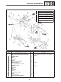
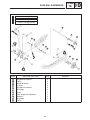
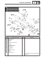
1
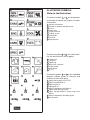
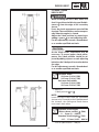
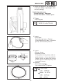
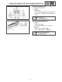
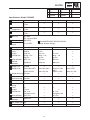
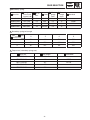
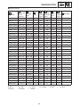
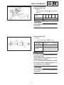
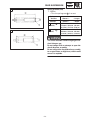
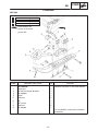
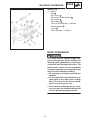
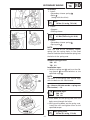
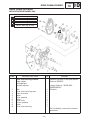
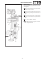
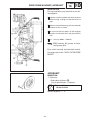
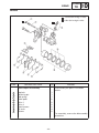
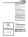
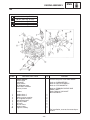
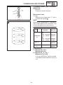
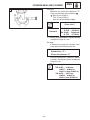
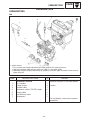
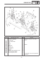
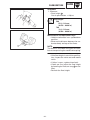
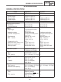
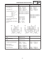
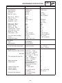
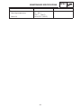
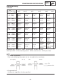
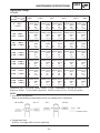
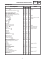
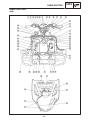
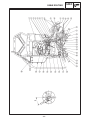
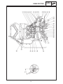
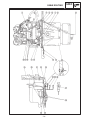
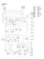
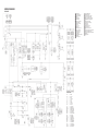
SUPPLEMENTARY SERVICE MANUAL FOREWORD This Supplementary Service Manual has been prepared to introduce new service and new data for the VX500SXBC, VX700ERC. For complete information, on service procedures, it is necessary to use this Supplementary Service Manual together with following manual: VT500A, VT600A, MM600A, MM700A VX500XTA/XTCA/XTCEA/XTCRA VX600XTA/XTCA/XTCEA/XTCRA/SXA VX700SXA SERVICE MANUAL: 8CY-28197-10 (LIT-12618-01-83) OE001 NOTICE This manual was written by the Yamaha Motor Company primarily for use by Yamaha dealers and their qualified mechanics. It is not possible to put an entire mechanic’s education into one manual, so it is assumed that persons using this book to perform maintenance and repairs on Yamaha snowmobiles have a basic understanding of the mechanical concepts and procedures inherent in snowmobile repair. Without such knowledge, attempted repairs or service to this model may render it unfit to use and/or unsafe. Yamaha Motor Company, Ltd. is continually striving to improve all models manufactured by Yamaha. Modifications and significant changes in specifications or procedures will be forwarded to all Authorized Yamaha dealers and will, where applicable, appear in future editions of this manual. OE022 VX500SXBC VX700ERC SUPPLEMENTARY SERVICE MANUAL 1998 by Yamaha Motor Corporation, U.S.A. 1st Edition, March 1998 All rights reserved. Any reprinting or unauthorized use without the written permission of Yamaha Motor Corporation, U.S.A. is expressly prohibited. Printed in U.S.A. OE011 HOW TO USE THIS MANUAL Particularly important information is distinguished in this manual by the following notations: The Safety Alert Symbol means ATTENTION! BE ALERT! YOUR SAFETY IS INVOLVED! Failure to follow WARNING instructions could result in severe injury or death to the snowmobile operator, a bystander, or a person inspecting or repairing the snowmobile. CAUTION: A CAUTION indicates special precautions that must be taken to avoid damage to the snowmobile. NOTE: A NOTE provides key information that can make procedures easier or clearer. MANUAL FORMAT All of the procedures in this manual are organized in a sequential, step-by-step format. The information has been compiled to provide the mechanic with an easy to read, handy reference that contains comprehensive explanations of all inspection, repair, assembly, and disassembly operations. If this revised format, the condition of a faulty component will precede an arrow symbol and the course of action required to correct the problem will follow the symbol, e.g., D Bearings Pitting /Damage ! Replace. EXPLODED DIAGRAM Each chapter provides exploded diagrams before each disassembly section to facilitate correct disassembly and assembly procedures. OE031 1 2 3 4 5 6 7 8 ILLUSTRATED SYMBOLS (Refer to the illustration) Illustrated symbols 1 to 9 are designed as thumb tabs to indicate the chapter’s number and content. 1 General information 2 Periodic inspection and adjustment 3 Chassis 4 Power train 5 Engine overhaul 6 Cooling system 7 Carburetion 8 Electrical 9 Specifications 9 11 12 13 14 15 16 17 18 19 20 21 22 23 24 25 26 Illustrated symbols 11 to 17 are used to identify the specifications which appear. 11 Filling fluid 12 Lubricant 13 Tightening 14 Wear limit, clearance 15 Engine speed 16 Special tool 17 Ω, V, A Illustrated symbols 18 to 26 in the exploded diagram indicate grade of lubricant and location of lubrication point. 18 Apply locking agent (LOCTITE) 19 Apply Yamabond No.5 20 Apply engine oil 21 Apply gear oil 22 Apply molybdenum disulfide oil 23 Apply wheel bearing grease 24 Apply low-temperature lithium-soap base grease 25 Apply molybdenum disulfide grease 26 Use new one CONTENTS GENERAL INFORMATION . . . . . . . . . . . . . . 1 MACHINE IDENTIFICATION . . . . . . . . . 1 FRAME SERIAL NUMBER . . . . . . . 1 ENGINE SERIAL NUMBER . . . . . . . 1 IMPORTANT INFORMATION . . . . . . . . 1 LOCTITE . . . . . . . . . . . . . . . . . . . . . . 1 POWER TRAIN . . . . . . . . . . . . . . . . . . . . . 2 DRIVE V-BELT . . . . . . . . . . . . . . . . . . 2 BRAKE PAD INSPECTION . . . . . . . . 4 SLIDE RUNNER INSPECTION . . . . 4 TUNING . . . . . . . . . . . . . . . . . . . . . . . . . . . 5 CLUTCH . . . . . . . . . . . . . . . . . . . . . . . 5 GEAR SELECTION . . . . . . . . . . . . . . 8 FRONT SUSPENSION . . . . . . . . . . 11 REAR SUSPENSION . . . . . . . . . . . 12 ENGINE . . . . . . . . . . . . . . . . . . . . . . . . . . . . . ENGINE ASSEMBLY . . . . . . . . . . . . . . . 500 . . . . . . . . . . . . . . . . . . . . . . . . . . . 700 . . . . . . . . . . . . . . . . . . . . . . . . . . . CYLINDER HEAD AND CYLINDER . . INSPECTION . . . . . . . . . . . . . . . . . . CARBURETION . . . . . . . . . . . . . . . . . . . . . . . CARBURETORS . . . . . . . . . . . . . . . . . . . 500 . . . . . . . . . . . . . . . . . . . . . . . . . . . 700 . . . . . . . . . . . . . . . . . . . . . . . . . . . ASSEMBLY . . . . . . . . . . . . . . . . . . . . 38 38 38 39 41 CHASSIS . . . . . . . . . . . . . . . . . . . . . . . . . . . . SKI (500) . . . . . . . . . . . . . . . . . . . . . . . . . INSPECTION . . . . . . . . . . . . . . . . . . FRONT SUSPENSION . . . . . . . . . . . . . INSTALLATION . . . . . . . . . . . . . . . . 14 14 15 15 16 POWER TRAIN . . . . . . . . . . . . . . . . . . . . . . . SECONDARY SHEAVE . . . . . . . . . . . . . ASSEMBLY . . . . . . . . . . . . . . . . . . . . DRIVE CHAIN HOUSING . . . . . . . . . . . WITHOUT REVERSE MODEL (500) . . . . . . . . . . . . . . . . . . . . . . . . . . INSTALLATION . . . . . . . . . . . . . . . . DRIVE CHAIN HOUSING AND JACKSHAFT INSTALLATION . . . . WITH REVERSE MODEL (700) . . . INSTALLATION . . . . . . . . . . . . . . . . JACKSHAFT . . . . . . . . . . . . . . . . . . . . . . INSPECTION . . . . . . . . . . . . . . . . . . BRAKE . . . . . . . . . . . . . . . . . . . . . . . . . . . BRAKE PAD REPLACEMENT . . . . SLIDE RAIL SUSPENSION . . . . . . . . . FRONT AXLE AND TRACK . . . . . . . . . INSTALLATION . . . . . . . . . . . . . . . . 17 17 17 18 SPECIFICATIONS . . . . . . . . . . . . . . . . . . . . . GENERAL SPECIFICATIONS . . . . . . . . MAINTENANCE SPECIFICATIONS . . ENGINE . . . . . . . . . . . . . . . . . . . . . . . POWER TRAIN . . . . . . . . . . . . . . . . CHASSIS . . . . . . . . . . . . . . . . . . . . . . ELECTRICAL . . . . . . . . . . . . . . . . . . . CABLE ROUTING <500> . . . . . . . . . . . CABLE ROUTING <700> . . . . . . . . . . . 42 42 44 44 48 52 53 60 70 18 19 20 21 23 23 23 24 25 27 32 32 33 33 33 34 35 35 COOLING SYSTEM . . . . . . . . . . . . . . . . . . . 37 HEAT EXCHANGER . . . . . . . . . . . . . . . 37 MACHINE IDENTIFICATION/IMPORTANT INFORMATION GEN INFO 1E001 GENERAL INFORMATION MACHINE IDENTIFICATION FRAME SERIAL NUMBER The frame serial number 1 is located on the right-hand side of the frame (just below the front of the seat). ENGINE SERIAL NUMBER The engine serial number 1 is located on the right-hand side of the crankcase. 500 NOTE: Designs and specifications are subject to change without notice. 700 IMPORTANT INFORMATION LOCTITE After installing fasteners that have LOCTITE applied, wait 24 hours before using the machine. This will give the LOCTITE time to properly dry. –1– DRIVE V-BELT INSP ADJ POWER TRAIN DRIVE V-BELT When installing the new V-belt, make sure that it is positioned within the specified distances 1 from the edge of the secondary sheave. If not, the clutch engagement speed will be changed. The machine may move unexpectedly when the engine is started. Adjust the V-belt position by removing or adding a spacer 2 on each adjusting bolt. For this adjustment, consult a Yamaha dealer or another qualified mechanic. CAUTION: As the V-belt wears, adjustment may be necessary. To ensure proper clutch performance, the V-belt position should be adjusted by adding a spacer on each adjusting bolt when the V-belt position reaches below the edge. For this adjustment, consult a Yamaha dealer or another qualified mechanic. New belt width: 35.0 mm (1.38 in) (500) 34.5 mm (1.36 in) (700) Belt wear limit width: 33.0 mm (1.30 in) (500) 32.5 mm (1.28 in) (700) 1. Measure: S V-belt position a or b NOTE: Install the new V-belt onto the secondary sheave only. Do not force the V-belt between the sheaves; the sliding and fixed sheave must touch each other. Standard V-belt height (Below sheave surface) a (500): 0 X 2 mm (0 X 0.08 in) Standard V-belt height b (700): –0.5 X 1.5 mm (–0.02 X 0.06 in) S Out of specification ! Adjust. –2– DRIVE V-BELT INSP ADJ 2. Adjust the position of the V-belt by removing or adding a spacer 1 on each adjusting bolt 2 . V-belt height adjustment To move V-belt up: Add spacer To move V-belt down: Reduce spacer 3. Tighten: S Adjusting bolt Adjusting bolt: 10 Nm (1.0 mSkg, 7.2 ftSlb) 4. Inspect: S Drive V-belt Cracks/damage/wear ! Replace. Oil or grease on the V-belt ! Check the primary and secondary sheaves. 5. Inspect: S Primary sheave S Secondary sheave Oil or grease on the primary and secondary sheaves ! Use a rag soaked in lacquer thinner or solvent to remove the oil or grease. Check the primary and secondary sheaves. 6. Measure: S Drive V-belt length a Out of specification ! Replace. Drive V-belt length: 500 1,119 X 1,129 mm (44.063 X 44.437 in) 700 1,129 X 1,137 mm (44.4 X 44.7 in) –3– BRAKE PAD INSPECTION/SLID RUNNER INSPECTION INSP ADJ BRAKE PAD INSPECTION 1. Apply the brake lever. 2. Inspect: S Brake pad Wear indicator 1 nearly contacts the brake disc ! Replace the brake pads as a set. Wear limit a : 4.7 mm (0.185 in) SLIDE RUNNER INSPECTION 1. Inspect: S Slide runner 1 Cracks/damage/wear ! Replace. 2. Measure: S Slide runner thickness 2 Out of specification ! Replace. Slide runner wear limit: 10 mm (0.39 in) –4– CLUTCH INSP ADJ TUNING W White S Silver L CLUTCH High altitude P R Red O Orange Pink Y Yellow Blue G Green Specifications Model: VX500SXB A Elevation X 3,500 ft B Idle speed Approx. 1,600 r / min C Clutch engagement Approx. 4,000 r / min D Shift speed Approx. 7,800 r / min E Main jet #151.3 (STD) F Pilot (slow) jet G Idle mixture screw #45 (STD) H Gearing I J K L Primary spring Color Length Preload rate M Wire diameter N Outside diameter 3,000 X 5,000 ft 4,500 X 7,000 ft 6,500 X 10,000 ft z z z 4,100 r / min z 4,200 r / min z z z d See MAINTENANCE SPECIFICATIONS (High altitude settings) 1-3 / 4 (STD) 22/39 (70L) 21/39 (68L) 20/39 (68L) W-P-W 78.7 mm 30 kg – 2.25 kg / mm ø5.5 mm z z z z Y-P-Y 77.4 mm 30 kg – 2.5 kg / mm ø5.8 mm ø60 mm z z O-P-O 74.6 mm 30 kg – 3.25 kg / mm ø6.0 mm z z None (OUT) z None (OUT) None (IN) None (IN) z z z z z z z z z z z z R 75 mm 90_ (3-6) 729 kgmm / rad ø5.3 mm z z z z z z z z z z z z ø69.5 mm z z z a Sec. torque cam 43_ z z z b Sec. clutch shim z z z O Weight (1D) P Weight rivet Q Weight bushing 8CR Steel 13.9 (OUT) Aluminum 10.3 (IN) Duralon R Roller outer dia. ø15.0 mm S Roller bushing Duralon T Pri. clutch shim None U Secondary spring V Color W Length X Preload rate Y Wire diameter Z Outside diameter 1.0 mm z Aluminum 10.3 (OUT) None (IN) 19/39 (68L) –5– CLUTCH INSP ADJ W white S Silver L P R Red O Orange Pink Y Yellow Blue G Green Specifications Model: VX700ER A Elevation X 3,500 ft 3,000 X 5,000 ft 4,500 X 7,000 ft 6,500 X 10,000 ft B Idle speed Approx. 1,600 r / min z z z C Clutch engagement D Shift speed Approx. 4,000 r / min z z z Approx. 8,300 r / min z z z E Main jet #1: #145 #2, 3: #143.8 (STD) F Pilot (slow) jet #45 (STD) G Idle mixture screw 1-1 / 2 (STD) H Gearing I J K L Primary spring Color Length Preload rate 22 / 39 (70L) d See MAINTENANCE SPECIFICATIONS (High altitude settings) z z 22 / 40 (70L) W-S-W 81.0 mm 35 kg – 2.25 kg / mm ø5.5 mm G-P-G 76.3 mm 30 kg – 2.75 kg / mm ø5.8 mm P 75.4 mm 30 kg – 3.0 kg / mm ø6.0 mm z z ø48.0 mm ø48.0 mm ø60.0 mm z O Weight (1D) P Weight rivet 8CH-00 Steel 10.3 (OUT) z Steel 10.3 (OUT) Q Weight bushing Steel 13.9 (IN) Duralon Steel 13.9 (IN) z z Aluminum 10.3 (OUT) Steel 13.9 (IN) z M Wire diameter N Outside diameter z z z None (OUT) Steel 13.3 (IN) z R Roller outer dia. ø14.5 mm S Roller bushing Duralon z z z z z z T Pri. clutch shim None z z z G 75 mm 60_ (3-3) 848 kgmm / rad ø5.5 mm z z ø69.5 mm z z z a Sec. torque cam 45_ z z z b Sec. clutch shim z z z U Secondary spring V Color W Length X Preload rate Y Wire diameter Z Outside diameter 1.0 mm z z –6– R z 60_ (3-3) 729 kgmm / rad ø5.3 mm z z z z CLUTCH INSP ADJ 2E331 The clutch may require tuning depending upon the area of operation and desired handling characteristics. The clutch can be tuned by changing engagement and shifting speed. Clutch engagement speed is defined as the engine speed where the machine first begins to move from a complete stop. Shifting speed is when the machine has been started at full-throttle from a dead stop and has travelled 200 X 300 m (650 X 1,000 ft). Normally, when a machine reaches shifting speed, the vehicle speed increases but the engine speed remains nearly constant. Under unfavorable conditions (wet snow, icy snow, hills, or rough terrain), however, engine speed may decrease after the shifting speed has been reached. A Engine speed B Good condition C Bad condition D Clutch shifting speed E Clutch engagement speed F Starting position G 200 X 300 m (650 X 1,000 ft) H Distance travelled –7– INSP ADJ GEAR SELECTION GEAR SELECTION The reduction ratio of the driven gear to the drive gear must be set according to the snow conditions. If there are many rough surfaces or unfavorable snow conditions, the drive/driven gear ratio should be increased. If the surfaces are fairly smooth or better snow conditions exist, decrease the ratio. Gear ratio chart The following drive and driven gears and chains are available as options. The figures in the upper lines represent the drive/driven gear ratios, while the number on the following line, followed by an “L”, designates the number of chain links. NOTE: Do not set the gearing to any of the indicated (x) settings. 1 Chain and sprocket parts number: A Parts name B Teeth & Links C Parts No. D Standard 18T 89J-17682-80 19T 89J-17682-91 20T 89J-17682-00 21T 89J-17682-10 22T 89J-17682-20 23T 89J-17682-30 39T 89J-47587-90 40T 89J-47587-00 39T (REVERSE) 8CW-47587-90 68LINKS 94860-02068 70LINKS 94860-02070 E Drive sprocket F Driven sprocket G Chain (links) VX500, VX700 VX500 VX700 VX500, VX700 2 Gear ratio A Drive gear 18T 19T 20T 21T 22T 23T 39T 2.17 68L 2.05 68L 1.95 68L 1.86 68L 1.77 70L 1.70 70L 40T* 2.22 68L 2.10 68L 2.00 68L 1.90 70L 1.82 70L 1.74 70L B Driven gear * Not for reverse models –8– GEAR SELECTION INSP ADJ 3 Secondary spring A Parts No. B Spring rate C No. of NSmm/ rad coils (kgmm/ rad) D Color E Wire gauge (mm) F Free length (mm) G Standard 90508-500B1 6003 (613) 5.2 BROWN 5.0 75 90508-536A9 7147 (729) 5.5 RED 5.3 75 VX500 90508-556A2 8314 (848) 5.5 GREEN 5.5 75 VX700 90508-556A7 9460 (965) 4.8 SILVER 5.5 75 4 Secondary spring twist angle A Seat 0 3 6 9 1 10_ 40_ 70_ 100_ 2 20_ 50_ 80_ 110_ 3 30_ 60_ 90_ 120_ B Sheave 5 Torque cam (secondary spring seat) A Parts No. B Cam angle 8BV-17604-10 41_ 8BV-17604-30 43_ VX500 8BV-17604-50 45_ VX700 8BV-17604-70 47_ 8BV-17604-90 39_ –9– C Standard INSP ADJ GEAR SELECTION 6 Primary spring B A Parts No. Spring rate N / mm (kg / mm) C Preload (kg) D Color E F Wire gauge (mm) Outside diameter (mm) G No. of coils H Free length (mm) 90501-481J1 9.8 (1.0) 196.1 (20) S-B-S 4.8 60 5.16 85.4 90501-487G8 14.7 (1.5) 147 (15) G 4.8 60 4.19 75.4 90501-507G2 14.7 (1.5) 196.1 (20) G-B-G 5.0 60 4.61 78.7 90501-524G5 14.7 (1.5) 245 (25) G-Y-G 5.2 60 5.08 82.1 90501-507G7 17.1 (1.75) 147 (15) R-G-R 5.0 60 4.24 74.0 90501-524G4 17.1 (1.75) 245 (25) R-Y-R 5.2 60 4.64 79.7 90501-526J9 17.2 (1.75) 294 (30) R-P-R 5.2 48 4.77 82.5 90501-527G1 17.2 (1.75) 196.1 (20) R-B-R 5.2 60 4.65 76.8 90501-525J8 19.6 (2.0) 294 (30) B-P-B 5.2 48 4.43 80.4 90501-526G4 19.6 (2.0) 147 (15) B-G-B 5.2 60 4.32 72.9 90501-553G0 19.6 (2.0) 245 (25) B-Y-B 5.5 60 5.10 78.0 90501-556G6 19.6 (2.0) 196.1 (20) B 5.5 60 4.95 75.4 90501-550J8 22 (2.25) 294 (30) W-P-W 5.5 60 4.62 78.7 90501-553G6 22 (2.25) 245 (25) W-Y-W 5.5 60 4.61 76.5 90501-555J9 22 (2.25) 343 (35) W-S-W 5.5 48 4.66 81.0 90501-556G5 22 (2.25) 196.1 (20) W-B-W 5.5 60 4.62 74.3 90501-557G6 22 (2.25) 147 (15) W-G-W 5.5 60 4.62 72.1 90501-556G7 24.5 (2.5) 196.1 (20) Y-G-Y 5.5 60 4.36 73.4 90501-581J7 24.5 (2.5) 245 (25) Y 5.8 60 4.96 75.4 90501-582J1 24.5 (2.5) 294 (30) Y-P-Y 5.8 60 4.96 77.4 90501-586J0 24.5 (2.5) 343 (35) Y-S-Y 5.8 48 4.91 79.4 90501-605G7 26.8 (2.74) 235 (24) G-Y-G 6.0 60 5.00 74.1 90501-585J3 27 (2.75) 294 (30) G-P-G 5.8 48 4.64 76.3 90501-607G0 27 (2.75) 196.1 (20) G-B-G 6.0 60 5.12 72.7 90501-607G4 27 (2.75) 147 (15) Gr-g-Gr 6.0 60 5.12 70.9 90501-602J0 29.4 (3.0) 294 (30) P 6.0 60 4.74 75.4 90501-604G0 29.4 (3.0) 235 (24) P-Y-P 6.0 60 4.80 73.3 90501-606G9 29.4 (3.0) 196.1 (20) P-B-P 6.0 60 4.86 72.1 90501-607G3 29.4 (3.0) 147 (15) P-G-P 6.0 60 4.86 70.4 90501-605J5 31.9 (3.25) 294 (30) Or-P-Or 6.0 48 4.53 74.6 Color B– Blue S– Silver G– Gold W– White Gr– Green Y– Yellow Or– Orange –10– P– Pink I Standard VX500 VX700 R– Red INSP ADJ FRONT SUSPENSION FRONT SUSPENSION Spring preload (700) 1. Adjust: S Turn the adjusting ring 1 to the proper position. Spring adjuster position 1 2 3 Preload Softer z Standard 1 4 5 ! Harder CAUTION: Be sure that the left and right spring preload is the same. Spring preload (500) 1. Adjust: S Turn the spring seat 1 in or out. Spring seat distance Preload a Length Standard Shorter z ! Longer Harder z ! Softer Max. Min. 213 mm 223 mm 233 mm (8.39 in) (8.78 in) (9.17 in) This shock absorber contains highly pressurized nitrogen gas. Do not tamper with or attempt to open the shock absorber assembly. Do not subject the shock absorber assembly to an open flame or high temperature, as this could cause it to explode. CAUTION: Be sure that the left and right spring preload is the same. –11– INSP ADJ REAR SUSPENSION REAR SUSPENSION Stopper band 1. Adjust: S Stopper band tension CAUTION: Be sure that the left and right length is the same. NOTE: This adjustment affects the handling characteristics of the machine. Adjustment steps: S Loosen the locknut 1 . S Turn the adjusting nut 2 in or out to adjust the stopper band tension. Adjuster Thread length Longer z ! Shorter maximum minimum STD 500 15 mm (0.59 in) 700 10 mm (0.39 in) Effects More weight on skis. Less weight transfer Less weight on skis. More weight transfer S Tighten the locknut. Spring preload (700) 1. Adjust: S Turn the adjusting ring 1 to the proper position. A Spring adjuster position B –12– 1 2 3 Preload Softer z A Standard (front) 1 Spring adjuster position 1 Preload Softer z B Standard (rear) 2 2 3 4 5 ! Harder 4 5 6 7 ! Harder REAR SUSPENSION INSP ADJ Spring preload (500) 1. Adjust: S Turn the spring seat 1 in or out. A B Spring seat distance Standard Shorter z ! Longer Preload Harder z ! Softer A Length a (front) Max. Min. 172 mm 182 mm 192 mm (6.77 in) (7.17 in) (7.56 in) B Length b (rear) Max. Min. 302 mm 312 mm 322 mm (11.89 in) (12.28 in) (12.68 in) This shock absorber contains highly pressurized nitrogen gas. Do not tamper with or attempt to open the shock absorber assembly. Do not subject the shock absorber assembly to an open flame or high heat, which could cause it to explode. –13– SKI CHAS CHASSIS SKI (500) A : 10 Nm (1.0 mSkg, 7.2 ftSlb) B : 21 Nm (2.1 mSkg, 15 ftSlb) C : 48 Nm (4.8 mSkg, 35 ftSlb) : ESSO beacon 325 grease or Aeroshell grease #7A Order 1 2 3 4 5 6 7 8 9 Job name/Part name Q’ty Ski removal Cotter pin Ski column lower bracket Ski stopper Collar Washers Ski Ski runner Washers Ski handle Remarks Remove the parts in the order below. 1 1 1 1 6 1 1 6 1 For installation, reverse the removal procedure. –14– SKI/FRONT SUSPENSION CHAS INSPECTION 1. Inspect: S Ski 1 S Ski runner 2 S Ski column lower bracket 3 S Ski handle 4 S Ski stopper 5 Wear/cracks/damage ! Replace. S Mounting bolt 6 S Collar 7 Wear/damage ! Replace. FRONT SUSPENSION This shock absorber contains highly compressed nitrogen gas. Before handling the shock absorber read and make sure that you understand the following information. The manufacturer cannot be held responsible for property damage or personal injury that may result from improper handling. D Do not tamper or attempt to open the gas chamber. D Do not subject the shock absorber to an open flame or any other source of high heat. This may cause the unit to explode due to excessive gas pressure. D Do not deform or damage the gas chamber in any way. Gas chamber damage will result in poor damping performance. –15– FRONT SUSPENSION CHAS INSTALLATION 1. Install: S Control rod 1 S Nut 2 S Joint 3 a Set length D Left hand C Model VX500 F Set length a (mm) H Upper I Lower VX700 H Upper I Lower B Set angle (_) 460.2 ± 0.5 mm (18.11 ± 0.0197 in) 94 ± 1 458.7 ± 0.5 mm (18.059 ± 0.0197 in) 94 ± 1 475.5 ± 0.5 mm (18.012 ± 0.0197 in) 93 ± 1 472.6 ± 0.5 mm (18.606 ± 0.0197 in) 93 ± 1 E Right hand C Model VX500 F Set length a (mm) H Upper I Lower VX700 H Upper I Lower B Set angle (_) 460.2 ± 0.5 mm (18.11 ± 0.0197 in) 86 ± 1 458.7 ± 0.5 mm (18.059 ± 0.0197 in) 86 ± 1 475.5 ± 0.5 mm (18.012 ± 0.0197 in) 87 ± 1 472.6 ± 0.5 mm (18.606 ± 0.0197 in) 87 ± 1 A 14 mm = 62 X 84 Nm (6.2 X 8.4 mSkg, 14 mm = 45 X 60 ftSlb) 2. Install: S Steering arm 1 NOTE: Align the punch mark a on the ski column with the punch mark b on the steering arm. Nut (steering arm): 54 Nm (5.4 mSkg, 38 ftSlb) –16– SECONDARY SHEAVE POWR TR ASSEMBLY 1. Install: S Secondary sheave spring 1 S Bolts 2 (along with the shims) Bolt: 10 Nm (1.0 mSkg, 7.2 ftSlb) 2. Install: S Stopper S Sliding sheave Screw (stopper): 6.5 Nm (0.65 mSkg, 4.6 ftSlb) 3. Install: S Secondary sheave spring 1 S Spring seat 2 NOTE: Hook the end of the secondary sheave spring into the spring holes in the fixed sheave. Hook the other end of the spring into the holes in the spring seat. Standard spring position: 500 3-6 700 3-3 Installation steps: D Hold the spring seat 1 and turn the sliding sheave 2 counterclockwise to the specified angle a . NOTE: The holes in the spring seat should align with the bolts on the fixed sheave. a = (sheave side hole number + spring seat hole number) 10 Standard angle: 500 90_ 700 60_ D Push down on the spring seat until the bolts come through the holes. D While pushing down on the spring seat, install the nuts and tighten them to the specified torque. Nut (spring seat): 23 Nm (2.3 mSkg, 17 ftSlb) –17– DRIVE CHAIN HOUSING POWR TR DRIVE CHAIN HOUSING WITHOUT REVERSE MODEL (500) A : 10 Nm (1.0 mSkg, 7.2 ftSlb) B : 24 Nm (2.4 mSkg, 17 ftSlb) C : 48 Nm (4.8 mSkg, 35 ftSlb) D : 60 Nm (6.0 mSkg, 43 ftSlb) Order Job name/Part name Q’ty Remove the parts in the order below. Refer to “BRAKE”. Drive chain housing removal Brake caliper Parking brake Tension adjuster 1 2 3 4 5 6 7 8 9 10 Remarks 1 1 1 1 1 1 1 1 1 1 Bolt Drive chain housing cover Chain tensioner Roller Drive sprocket Collar Drive chain Driven sprocket Collar Drive chain housing Loosen. Refer to “SLIDE RAIL SUSPENSION”. Oil drain. For installation, reverse the removal procedure. –18– DRIVE CHAIN HOUSING POWR TR INSTALLATION During installation, pay attention to the following point: A Make sure that the bearing seals face towards the drive chain, as shown. B Properly install the rubber seal onto the drive chain housing, making sure that these are no gaps. C Be sure to install the spacers in their original positions of the brake disc and jackshaft will stick. D 0.1 X 0.5 mm (0.004 X 0.020 in) : ESSO beacon 325 grease or Aeroshell grease #7A –19– DRIVE CHAIN HOUSING POWR TR DRIVE CHAIN HOUSING AND JACKSHAFT INSTALLATION 1. Install: S Drive chain housing S Jackshaft Installation steps: D Install the drive chain housing 1 . D Tighten the bolts 2 . Bolt (drive chain housing): 48 Nm (4.8 mSkg, 35 ftSlb) D Temporarily tighten the nuts 3 . D Tighten the nuts 3 . Nut (jackshaft): 60 Nm (6.0 mSkg, 43 ftSlb) D Retighten the nuts 3 . Nut (bearing holder): 23 Nm (2.3 mSkg, 17 ftSlb) D Tighten the set screws 5 . Set screw (bearing): 8.5 Nm (0.85 mSkg, 6.1 ftSlb) D Install the drive chain housing cover 6 . D Tighten the bolts 7 . Bolt (drive chain housing cover): 24 Nm (2.4 mSkg, 17 ftSlb) –20– DRIVE CHAIN HOUSING POWR TR WITH REVERSE MODEL (700) Order Job name/Part name 10 Nm (1.0 mSkg, 7.2 ftSlb) B : 24 Nm (2.4 mSkg, 17 ftSlb) C : 48 Nm (4.8 mSkg, 35 ftSlb) D : 60 Nm (6.0 mSkg, 43 ftSlb) Q’ty Drive chain housing removal Battery Battery bracket Brake caliper Parking brake Tension adjuster 1 2 3 4 5 6 7 8 9 A : Remarks Remove the parts in the order below. Refer to “BRAKE”. Loosen. Refer to “SLIDE RAIL SUSPENSION”. Joints Shift rod Shift lever assembly Lever Joints Lever rod Bolt Drive chain housing cover Washer 2 1 1 1 2 1 1 1 1 –21– Oil drain. DRIVE CHAIN HOUSING Order 10 11 12 13 14 15 16 17 18 19 20 21 22 23 24 25 26 27 28 Job name/Part name Q’ty Reverse drive gear Spring Chain tensioner Roller Collar Spring Journal Reverse driven gear Washer Forward driven sprocket Collar Counter gear Drive sprocket Drive chain Collar Washer Plate Shaft Drive chain housing POWR TR Remarks 1 1 1 1 1 1 1 1 1 1 1 1 1 1 1 1 1 1 1 For installation, reverse the removal procedure. –22– DRIVE CHAIN HOUSING/JACKSHAFT POWR TR INSTALLATION During installation, pay attention to the following point: A Properly install the rubber seal onto the drive chain housing, making sure that these are no gaps. B Make sure that the bearing seals face towards the drive chain, as shown. C Be sure to install the spacers in their original positions of the brake disc and jackshaft will stick. D 0.1 X 0.5 mm (0.004 X 0.020 in) : ESSO beacon 325 grease or Aeroshell grease #7A Drive chain housing and jackshaft installation steps refer to the “WITH OUT REVERSE MODEL”. JACKSHAFT INSPECTION 1. Measure: S Brake disc thickness a Out of specification ! Replace. Minimum thickness: 10 mm (0.39 in) Measuring point 1 X 3 –23– BRAKE POWR TR BRAKE A : 1.5 Nm (0.15 mSkg, 1.1 ftSlb) B : 6 Nm (0.6 mSkg, 4.3 ftSlb) A Order B Job name/Part name Q’ty Brake caliper disassembly 1 2 3 4 5 6 7 8 9 Remarks Disassembly the parts in the order below. Cap bolt Retaining pin Pad spring Brake pads Shim 1 Shim 2 Bleed screws Oil seals Pistons 1 1 1 2 2 2 2 4 2 For assembly, reverse the disassembly procedure. –24– BRAKE POWR TR CAUTION: Disc brake components rarely require disassembly. DO NOT: D Disassemble components unless absolutely necessary. D Use solvents on internal brake components. D Use contaminated brake fluid for cleaning. Use only clean brake fluid. D Allow brake fluid to come in contact with the eyes, otherwise eye injury may occur. D Allow brake fluid to contact painted surfaces or plastic parts otherwise damage may occur. D Disconnect any hydraulic connection ofherwise the entie system must be disassembled, drained, cleaned, and then properly filled and bled after reassembly. BRAKE PAD REPLACEMENT NOTE: It is not necessary to disassemble the brake caliper and brake hose to replace the brake pads. 1. Remove: S Brake pads 1 NOTE: D Do not depress the brake lever when the caliper or disc is off the machine otherwise the brake pads will be forced shut. D Install new brake pad spring and shims when the brake pads have to be replaced. D Replace the pads as a set if either is found to be worn to the wear limit a . Wear limit a : 4.7 mm (0.185 in) –25– BRAKE POWR TR 2. Install: S Brake pads S Pad spring Installation steps: S Connect a suitable hose 1 tightly to the caliper bleed screw 2 . Put the other end of this hose into an open container. S Loosen the caliper bleed screw and push the pistons into the caliper with the finger. S Tighten the caliper bleed screw 2 . Bleed screw: 6 Nm (0.6 mSkg, 4.3 ftSlb) S Install the brake pads and pad spring. NOTE: The tangs a of the pad spring must point in the direction of the disc rotation. 3. Inspect: S Brake fluid level Refer to “BRAKE FLUID LEVEL INSPECTION”. 4. Check: S Brake lever operation A soft or spongy feeling ! Bleed brake system. Refer to “AIR BLEEDING (HYDRAULIC BRAKE SYSTEM)”. –26– SLIDE RAIL SUSPENSION POWR TR SLIDE RAIL SUSPENSION A : Order 1 2 3 4 71 Nm (7.1 mSkg, 51 ftSlb) Job name/Part name Q’ty Slide rail suspension removal Tension adjuster Blind caps Bolts Washer Slide rail suspension Remarks Remove the parts in the order below. Loosen. 2 6 2 1 For installation, reverse the removal procedure. –27– SLIDE RAIL SUSPENSION Order Job name/Part name 1 2 3 4 5 6 7 8 9 10 11 12 13 14 15 16 17 A : 4 Nm (0.4 mSkg, 2.9 ftSlb) B : 15 Nm (1.5 mSkg, 11 ftSlb) C : 30 Nm (3.0 mSkg, 22 ftSlb) D : 49 Nm (4.9 mSkg, 35 ftSlb) E : 71 Nm (7.1 mSkg, 50 ftSlb) F : 24 Nm (2.4 mSkg, 17 ftSlb) Q’ty Slide rail suspension disassembly POWR TR Remarks Disassemble the parts in the order below. 2 2 4 2 1 2 1 1 2 2 1 4 2 2 2 2 2 Stopper bands Hooks Bushings Collars Front shock absorber Rubber damper Front suspension bracket Front pivot arm Bracket Bushings Shaft Bushings Collars Suspension wheels Collar Wheel brackets Front pivot arm brackets –28– (700) (700) SLIDE RAIL SUSPENSION A : 24 Nm (2.4 mSkg, 17 ftSlb) B : 49 Nm (4.9 mSkg, 35 ftSlb) C : 71 Nm (7.1 mSkg, 50 ftSlb) POWR TR 24 23 26 22 27 28 27 26 21 20 19 25 Order 18 19 20 21 22 23 24 25 26 27 28 Job name/Part name Q’ty Suspension wheels Collar Wheel brackets Circlips Suspension wheels Bushings Shaft Rear suspension bracket Spacers Bushings Collar 2 2 2 2 2 2 1 1 2 2 1 –29– Remarks 18 SLIDE RAIL SUSPENSION A : 49 Nm (4.9 mSkg, 35 ftSlb) B : 71 Nm (7.1 mSkg, 50 ftSlb) Order 29 30 31 32 33 34 35 36 37 38 39 40 Job name/Part name Q’ty Rear shock absorber Bushings Collar Pull rod Collars Bushings Collars Suspension wheels Control rods Bushings Screw Bushings 1 2 1 2 4 4 2 2 2 2 2 2 –30– POWR TR Remarks (700) SLIDE RAIL SUSPENSION A : 24 Nm (2.4 mSkg, 17 ftSlb) B : 71 Nm (7.1 mSkg, 50 ftSlb) C : 75 Nm (7.5 mSkg, 54 ftSlb) POWR TR 50 51 52 45 42 41 54 51 46 55 56 44 42 43 56 53 47 48 52 49 51 48 Order 41 42 43 44 45 46 47 48 49 50 51 52 53 54 55 56 47 Job name/Part name Q’ty Rear pivot arm Bushings Collar Collar Rear pivot arm bracket Collar Circlips Suspension wheels Wheel bracket Rear axle Guide wheels Collars Tension adjusters Collar Collar Sliding frames Remarks 1 2 1 1 1 1 2 2 1 1 3 2 2 1 1 2 For assembly, reverse the disassembly procedure. –31– FRONT AXLE AND TRACK A FRONT AXLE AND TRACK 27 mm (1.06 in) 132.6 mm (5.22 in) 164.1 mm (6.46 in) B 102 mm (4.0157 in) 43.1 mm (1.70 in) 60 mm (2.36 in) 39 mm (1.535 in) 201.4 mm (7.93 in) NOTE: D When pressing the sprocket wheels onto the front axle, align the lugs on each sprocket wheel. D Locate each sprocket wheel and guide wheel on the axle where shown in the illustration. 102 mm (4.0157 in) 39 mm (1.535 in) 60 mm (2.36 in) 132.6 mm (5.22 in) 164.1 mm (6.46 in) INSTALLATION Reverse the “REMOVAL” procedure. Note the following points. 1. Install: S Sprocket wheels S Guide wheels 123 mm (4.84 in) 123 mm (4.84 in) POWR TR A : 500 B : 700 111.9 mm (5.22 in) 201.4 mm (7.93 in) 2. Place the track in the chassis. NOTE: Be sure it is positioned as shown in the illustration. A TURNING DIRECTION –32– ENG ENGINE ASSEMBLY ENGINE ENGINE ASSEMBLY 500 A : 90 Nm (9.0 mSkg, 65 ftSlb) B : 60 Nm (6.0 mSkg, 43 ftSlb) A B 8 Order Job name/Part name Q’ty Engine removal Exhaust pipe Carburetor Recoil starter Water pump Remove the parts in the order below. Refer to “CARBURETOR”. Refer to “RECOIL STARTER”. Refer to “WATER PUMP AND THERMOSTATIC VALVE”. Refer to “PRIMARY SHEAVE AND DRIVE V-BELT”. Primary sheave 1 2 3 4 5 6 7 8 Remarks Coolant hose Oil hoses Oil pump cable Vacuum hose CDI magneto couplers Thermo sensor coupler Spark plug caps Engine assembly 1 2 1 1 2 1 2 1 For installation, reverse the removal procedure. –33– ENGINE ASSEMBLY ENG 700 A : 23 Nm (2.3 mSkg, 17 ftSlb) B : 60 Nm (6.0 mSkg, 43 ftSlb) C : 90 Nm (9.0 mSkg, 65 ftSlb) D : 23 Nm (2.3 mSkg, 17 ftSlb) Order Job name/Part name Q’ty Engine removal Exhaust pipe Carburetor Recoil starter CDI Magneto rotor Frame cross member Primary sheave Remove the parts in the order below. Refer to “CARBURETOR”. Refer to “RECOIL STARTER”. Refer to “CDI MAGNETO”. Refer to “PRIMARY SHEAVE AND DRIVE V-BELT”. Drain. Refer to “COOLANT REPLACEMENT”. Coolant 1 2 3 4 5 6 7 8 9 10 Remarks Coolant hose 1 Coolant hose 2 Thermo sensor coupler CDI magneto couplers Rear bracket right Oil pump cable Oil hoses Vacuum hose Starter motor Engine assembly 1 1 1 2 1 1 2 1 1 1 For installation, reverse the removal procedure. –34– ENG CYLINDER HEAD AND CYLINDER CYLINDER HEAD AND CYLINDER INSPECTION 1. Measure: S Piston-to-cylinder clearance Measurement steps: 1st step: S Measure the cylinder bore “C” with a cylinder bore gauge 1 . NOTE: Measure the cylinder bore “C” parallel to, and at right angles to the crankshaft. Then find the average of the measurements. C Standard Cylinder bore “C” 500: 68.00 X 68.02 mm (2.677 X 2.678 in) 700: 70.50 X 70.52 mm (2.775 X 2.776 in) Wear limit 68.1 mm (2.681 in) 70.6 mm (2.780 in) Taper “T” – 0.05 mm (0.0019 in) Out of round “R” – 0.01 mm (0.0004 in) C = Maximum D T = (Maximum D1 or D2) – (Maximum D5 or D6) R = (Maximum D1, D3 or D5) – (Minimum D2, D4 or D6) S If out of specification, replace cylinder, and replace piston and piston rings as a set. –35– CYLINDER HEAD AND CYLINDER ENG 2nd step: S Measure the piston skirt diameter “P” with a micrometer from distance a . a 500: 25 mm (0.98 in) 700: 15 mm (0.59 in) from the piston bottom edge. P Piston size P Standard 500: 67.930 X 67.935 mm (2.6745 X 2.6746 in) 700: 70.425 X 70.430 mm (2.7727 X 2.7728 in) S If out of specification, replace piston and piston rings as a set. 3rd step: S Calculate the piston-to-cylinder clearance with the following formula: Piston-to-cylinder clearance = Cylinder bore “C” – Piston skirt diameter “P” S If out of specification, rebore or replace cylinder, and replace piston and piston rings as a set. Piston-to-cylinder clearance: 500: 0.095 X 0.100 mm (0.0037 X 0.0039 in) Limit 0.11 mm (0.0043 in) 700: 0.070 X 0.075 mm (0.0028 X 0.0030 in) Limit 0.1 mm (0.0039 in) –36– HEAT EXCHANGER COOL COOLING SYSTEM HEAT EXCHANGER 1. Measure: S Filler cap opening pressure Cap opens at pressure below the specified pressure ! Replace. Cap opening pressure: 95 X 125 kPa (0.95 X 1.25 kg/cm2, 13.58 X 17.87 psi) Measurement steps: D Attach the cooling system tester 1 (90890-01325, YU-24460-01) to the coolant filler cap 2 . D Apply the specified pressure for 10 seconds, and make sure there is no pressure drop. –37– CARBURETORS CARB CARBURETION CARBURETORS 500 3 4 1 5 2 7 2 6 * Intake silencer D First, remove the throttle cable from the cable guide on the steering column. D Adjust the throttle cable free play while the cable is in the cable guide. D After adjusting the throttle cable free play, properly install the upper and lower intake silencer plates and seal. Order 1 2 3 4 5 6 7 Job name/Part name Q’ty Carburetors removal Air chamber Clamp screws Throttle cable Carburetor switch (T.O.R.S.) leads Starter cable Fuel delivery hoses Carburetors Remarks Remove the parts in the order below. 1 4 1 2 1 2 1 Loosen For installation, reverse the removal procedure. –38– CARBURETORS CARB 700 * Intake silencer D First, remove the throttle cable from the cable guide on the steering column. D Adjust the throttle cable free play while the cable is in the cable guide. D After adjusting the throttle cable free play, properly install the upper and lower intake silencer plates and seal. Order 1 2 3 4 5 6 7 8 9 Job name/Part name Q’ty Carburetors removal Spark plug caps Clamp screws Carburetor switch (T.O.R.S.) leads Clamp Coolant hoses Throttle cable Starter cable Fuel hoses Carburetors Remarks Remove the parts in the order below. 3 6 2 1 3 1 1 3 1 Loosen For installation, reverse the removal procedure. –39– CARBURETORS Order Job name/Part name Q’ty Carburetor separation 1 2 3 4 5 6 7 8 9 10 11 12 13 14 CARB Remarks Separation the parts in the order below. Coolant hoses Starter cable holder Collar Spring Screw Starter rod Spring Starter levers Breather hoses Top covers Gaskets Throttle shaft connecting screws Connecting plate (upper) Connecting plate (lower) 4 1 1 1 3 1 1 3 3 3 3 3 1 1 Loosen For assembly, reverse the separation procedure. –40– CARBURETORS CARB ASSEMBLY 1. Measure: S Float height a Out of specification ! Adjust. Float height: 500 22.3 ± 2.0 mm (0.878 ± 0.080 in) 700 13.3 ± 2.0 mm (0.524 ± 0.080 in) Measurement and adjustment steps: S Hold the carburetor in an upside down position. S Measure the distance between the carburetor body and top of the floats. NOTE: The float arm should be resting on the valve, but not compressing the needle valve spring. S If the float height is not within specification, inspect the valve seat and needle valve. S If either is worn, replace them both. S If both are fine, adjust the float height by bending the float arm tang 1 on the float. S Recheck the float height. –41– GENERAL SPECIFICATIONS SPEC SPECIFICATIONS GENERAL SPECIFICATIONS Model VX500SXB VX700ER Model code number: 8CT 8DY Dimensions: Overall length Overall width Overall height 2,760 mm (108.7 in) 1,170 mm (46.1 in) 1,085 mm (42.7 in) z 1,200 mm (47.2 in) 1,300 mm (51.2 in) Weight: 222 kg (488 lb) 236 kg (520 lb) Minimum turning radius: Clockwise Counterclockwise 3.8 m (12.5 ft) 3.8 m (12.5 ft) 4.0 m (13.1 ft) 4.0 m (13.1 ft) Liquid cooled 2-stroke, piston port PIston reed valve Forward inclined parallel 2-cylinder 494 cm3 (30.1 cu.in) 68 68 mm (2.68 2.68 in) 6.5 : 1 7,750 ± 250 r/min 7,750 ± 250 r/min Recoil hand starter z Separate lubrication (YAMAHA AUTOLUBE) z YAMALUBE 2-cycle oil 3.0 L (2.6 Imp gt, 3.2 Us gt) z z Gear oil API “GL-3” SAE #75 or #80 0.25 L (8.8 Imp oz, 8.45 US oz) z 3.2 L (2.8 Imp gt, 3.4 US gt) 0.17 L (0.15 Imp gt, 0.18 US gt) 4.2 L (3.6 Imp gt, 4.3 US gt) z Regular gasoline R+M (Pump Octane R +2 M ; 88) 44.3 L (9.7 Imp gal, 11.7 US gal) z Engine: Engine type Induction system Cylilnder arrangement Displacement Bore stroke Compression ratio Maximum horse power r/min Maximum torque r/min Starting system Lubrication system: Engine oil: Type Tank capacity Drive chain housing oil: Type Capacity Coolant: Total amount Reservoir tank capacity Fuel: Type Tank capacity –42– Crankcase reed valve Forward indined parallel 3-cylinder 698 cm3 (42.6 cu.in) 70.5 59.6 mm (2.78 2.35 in) 6.7 : 1 8,500 ± 250 r/min 8,250 ± 250 r/min Electric and recoil hand starter z z SPEC GENERAL SPECIFICATIONS Model VX500SXB VX700ER TM36 2 MIKUNI TM33 z BR9ES NGK 0.7 X 0.8 mm (0.028 X 0.031 in) z z z V-Belt 3.8 X 1.0 : 1 Automatic centrifugal engagement Chain 1.77 (39/22) No z z z Chassis: Frame type Caster Ski stance (center to center) Monocoque 22.5_ 1,040 mm (40.9 in) z z 1,070 mm (42.1 in) Suspension: Front suspension type Rear suspension type Leading arm Slide rail suspension z z Track: Track type Track width Length on ground Track deflection mm/10 kg (22 lb) Internal drive type 381 mm (15.0 in) 752 mm (29.6 in) 25 X 30 mm (0.98 X 1.18 in) z z z z Caliper type disc brake Handle lever, left hand operated z z Electrical: Ignition system/manufacturer Generator system CDI/MITSUBISHI Flywheel magneto z z Bulb wattage quantity: Headlight Tail/brake light Tachometer light Speedometer light Highbeam indicator light Water temperature light Oil level indicator light 12 V, 60/55 W 1 12 V, 8/23 W 1 12 V, 1.7 W 1 12 V, 1.7 W 1 12 V, 1.7 W 1 12 V, 1.7 W 1 12 V, 1.7 W 1 z z z z z z z Carburetor: Type/quantity Manufacturer Spark plug: Type Manufacturer Gap Transmission: Primary reduction system Primary reduction ratio Clutch type Secondary reduction system Secondary reduction ratio Reverse system Brake: Brake type Operation method –43– 3 z z Yes MAINTENANCE SPECIFICATIONS SPEC MAINTENANCE SPECIFICATIONS ENGINE Model Cylinder head: Volume (with spark plug) <Warp limit> 500 VX500SXB VX700ER 23.3 X 23.9 cm3 <0.03 mm (0.0012 in)> * Lines indicate straight edge measurement. 22.9 X 23.5 cm3 z z Aluminum alloy with dispersion coating 68.00 X 68.02 mm (2.677 X 2.678 in) <0.05 mm (0.0019 in)> <0.01 mm (0.0004 in)> z 67.930 X 67.935 mm (2.6745 X 2.6746 in) 25 mm (0.98 in) 0.095 X 0.100 mm (0.0037 X 0.0039 in) <0.11 mm (0.0043 in)> 20.004 X 20.015 mm (0.7876 X 0.7880 in) 70.425 X 70.430 mm (2.7727 X 2.7728 in) 15 mm (0.59 in) 0.070 X 0.075 mm (0.0028 X 0.0030 in) <0.1 mm (0.0039 in)> z 19.995 X 20.000 mm (0.7872 X 0.7874 in) 55.7 X 56.0 mm (2.193 X 2.205 in) z Keystone B = 1.2 mm (0.047 in) T = 2.65 mm (0.104 in) Keystone B = 1.2 mm (0.047 in) T = 2.65 mm (0.104 in) 0.45 X 0.60 mm (0.0178 X 0.024 in) 0.45 X 0.60 mm (0.0178 X 0.024 in) 0.02 X 0.06 mm (0.0008 X 0.0024 in) 0.02 X 0.06 mm (0.0008 X 0.0024 in) Chrome plate / Ferox coating Chrome plate / Ferox coating z z T = 2.55 mm (0.100 in) z z T = 2.55 mm (0.100 in) 0.35 X 0.55 mm (0.0137 X 0.0217 in) 0.35 X 0.55 mm (0.0137 X 0.0217 in) z 700 Cylinder: Material Bore size <Taper limit> <Out-of-round limit> Piston: Piston size (D) Measuring point a Piston to-cylinder clearance <Limit> Piston pin bore inside diameter Piston pin: Piston pin outside diameter Piston pin length Piston ring: Sectional sketch Top Ring 2nd Ring End gap (installed) Top Ring 2nd Ring Side clearance Top Ring 2nd Ring Coating Top Ring 2nd Ring –44– 70.50 X 70.52 mm (2.775 X 2.776 in) z z z z z z MAINTENANCE SPECIFICATIONS Model Crankshaft: Crank width “A” Crank width “B” Crankshaft deflection “C” : C1 500: C2, C3 500: C4 700: C2 X C5 700: C6 Measuring points: 1 Measuring points: 2 Connecting rod big end side clearance “D” Connecting rod small end free play “F” SPEC VX500SXB VX700ER 61.95 X 62.00 mm (2.439 X 2.440 in) 179.85 X 180.15 mm (7.080 X 7.093 in) Below 0.03 mm (0.0012 in) Below 0.04 mm (0.0016 in) Below 0.05 mm (0.0020 in) – – 80 mm (3.15 in) 99 mm (3.90 in) 0.25 X 0.75 mm (0.01 X 0.03 in) 0.8 X 1.0 mm (0.03 X 0.04 in) 55.95 X 56.00 mm (2.203 X 2.205 in) 291.75 X 292.30 mm (11.486 X 11.508 in) z z z Below 0.04 mm (0.0016 in) Below 0.03 mm (0.0012 in) 90 mm (3.54 in) 85 mm (3.35 in) z 500 z 700 Big end bearing: Type Needle bearing z Small end bearing: Type Needle bearing z 24.987 X 25 mm (0.9838 X 0.9842 in) 26.993 X 27.000 mm (1.0627 X 1.0629 in) 24.995 X 25.008 mm (0.9841 X 0.9845 in) 32.005 X 32.018 mm (1.26004 X 1.26055 in) z Crank pin: Crank pin outside diameter Connecting rod: Small end diameter Big end diameter –45– 34.020 X 34.033 mm (1.3394 X 1.3398 in) MAINTENANCE SPECIFICATIONS Model Carburetor: Type/Quantity Manufacturer I.D. mark Main jet (M.J) VX500SXB VX700ER TM36/2 pcs. MIKUNI 8CJ10 #151.3 SPEC Main air jet (M.A.J) Pilot jet (P.J) Jet needle (J.N) Needle jet (N.J) ø2.5 #45 8CFY14-56-2 Q-6 Pilot air jet (P.A.J) Pilot outlet (P.O) Bypass (B.P.I) Pilot screw (P.S) Throttle valve (Th.V) Valve seat size (V.S) Starter jet (G.S) Float height (F.H) 2.5 ø0.9 1.0 1-3/4 3.0 ø1.5 ø0.9 22.3 ± 2.0 mm (0.878 ± 0.080 in) 41 mm (1.61 in) 1,600 ± 100 r/min TM33/3 pcs. z 8CH10 #1 : #145 #2, 3 : #143.8 – z 6DGM5-3 #1 : Q-8 #2, 3 : Q-4 1.0 ø0.8 0.8 1-1/2 3.5 ø1.2 ø1.1 13.3 ± 2.0 mm (0.524 ± 0.080 in) 37 ± 1 mm (1.457 ± 0.039 in) z Fuel pump: Type Manufacturer DIAPHRAM TAIYO GIKEN z z Oil pump: Pump cable adjusting length Align the marks 21 X 23 mm (0.83 X 0.90 in) 8 mm/10 X 14 kg (0.3 in/22.0 X 30.9 lb) 8 mm/13 X 20 kg (0.31 in/28.7 X 44.1 lb) 95 X 125 kPa (0.95 X 1.25 kg/cm2, 13.58 X 17.87 psi) Impeller type High quality ethylene glycol antifreeze containing corrosion innibitor 3 : 2 (60%/40%) – 3.2 L (2.81 Imp qt, 3.4 US qt) 0.17 L (0.15 Imp qt, 0.18 US qt) 4.2 L (3.6 Imp qt, 4.3 US qt) z Fuel level (from the bore center) Engine idle speed Cooling system: Water pump drive belt tension New belt Filler cap opening pressure Water pump type Coolant type Coolant mixing ratio (coolant: water) Coolant capacity Reservoir tank capacity –46– – z z z z z MAINTENANCE SPECIFICATIONS Model Thermostat: Opening temperature Valve lift VX500SXB VX700ER 50 X 55_C (122_F X 132_F) 8 mm/70_C (159_F) z –47– z SPEC MAINTENANCE SPECIFICATIONS SPEC POWER TRAIN Model Transmission: Type Range of ratio Engagement r/min Shift r/min Sheave center distance “A” Sheave offset “B” V-Belt: Part number Outside circumference Width “A” Wear limit “B” Primary sheave spring: Part number Color code Diameter Wire diameter Preload Spring rate Number of coils Free length Primary sheave weight arm: Part number (with bushing) Weight VX500SXB VX700ER V-belt automatic 3.8 X 1.0 : 1 4,000 ± 200 r/min 7,800 ± 250 r/min 267 X 270 mm (10.52 X 10.62 in) 13.5 X 16.5 mm (0.53 X 0.64 in) z z z 8,300 ± 250 r/min z 8CJ-17641-00 DAYCO 1,119 mm X 1,129 mm (44.063 X 44.437 in) 35.0 mm (1.38 in) 33.0 mm (1.30 in) 8DN-17641-00 MITSUBOSHI 1,129 mm X 1,137 mm (44.4 X 44.7 in) 34.5 mm (1.36 in) 32.5 mm (1.28 in) 90501-550J8 White-Pink-White 60 mm (2.36 in) 5.5 mm (0.21 in) 294 N (30 kg, 66 lb) 22 N/mm (2.25 kg/mm, 123 lb/in) 4.62 78.7 mm (3.10 in) 90501-555J9 White-Silver-White 48 mm (1.89 in) z 343 N (35 kg, 77 lb) z 8CR-17605-00 38.09g (1.34oz) 8CH-17605-10 35.32g (1.24oz) –48– 18.5 X 21.5 mm (0.75 X 0.84 in) 4.66 81.0 mm (3.19 in) MAINTENANCE SPECIFICATIONS Model Rivet: Outer Part number Material Size Quantity Hole quantity Inner Part number Material Size Quantity Hole quantity Secondary sheave spring: Part number Color code Outside diameter Wire diameter Hole position Sheave side-spring side (twist angle) Spring rate Number of coils Free length Torque cam angle Drive chain: Type Number of links SPEC VX500SXB VX700ER 90261-06034 Steel 13.9 mm (0.55 in) 3 pcs 3 pcs 90261-06015 z 10.3 mm (0.40 in) z z 90261-06028 Aluminum 10.3mm (0.40in) 3 pcs 3 pcs 90261-06034 Steel 13.9 mm (0.55 in) z z 90508-536A9 Red 69.5 mm (2.736 in) 5.3 mm (0.208 in) 90508-556A2 Green z 5.5 mm (0.216 in) 3-6 (90_) 3-3 (60_) 7.23 N/mm (0.74 kg/mm, 40.49 lb/in) 5.53 75 mm (2.95 in) 43_ 8.49 N/mm (0.866 kg/mm, 47.54 lb/in) z z 45_ S37TNB13 70L z z –49– MAINTENANCE SPECIFICATIONS Model SPEC VX500SXB VX700ER 8AB-47110-10 381 mm (15.0 in) 3,072 mm (120.9 in) 64 mm (2.52 in) 48 16 mm (0.63 in) 8CH-47110-00 z z z z z 25 X 30 mm (0.98 X 1.18 in) z 178 mm (7 in) 203 mm (8 in) 228 mm (9 in) 279 mm (11 in) 47 N/mm (4.8 kg/mm, 274 lb/in) 27.44 X 47.04 N/mm (2.8 X 4.8 kg/mm, 160 X 273 lb/in) 19.6 N/mm (2 kg/mm, 112 lb/in) 29.4 X 44.1 N/mm (3.0 X 4.5 kg/mm, 174 X 251 lb/in) Spring wire diameter Front Rear 9.0 mm (0.35 in) 10.8 mm (0.425 in) 7.8 mm (0.30in) 11.5 mm (0.45 in) Suspension setting position: Stopper band hole position (F) Hook setting length * NO.1 15 mm (0.59 in) z 10 mm (0.39 in) B z Track: Part number Width Length Pitch Number of links Height “B” Deflection at 10 kg (22 lb) Slide rail suspension: Front travel Rear travel Suspension spring rate Front Rear Full rate adjusting position ** –50– MAINTENANCE SPECIFICATIONS Model SPEC VX500SXB VX700ER 3,320N ± 460N/0.3m/s 1,110N ± 225N/0.3m/s 720 N ± 150N/0.3m/s 1,020 N ± 210N/0.3m/s 1,950N ± 264N/0.3m/s 1,380N ± 235N/0.3m/s 2,206 N ± 657N/0.3m/s 726 N ± 216N/0.3m/s Slide runner: Thickness Wear limit 17.8 mm (0.70 in) 10 mm (0.39 in) z z Track sprocket wheel: Material Number of teeth Polyethylene 9T z z Rear guide wheel: Material Aluminum with rubber 178 mm (7 in) High-molecular-weight polyethylene with rubber z 10.2 mm (0.40 in) 4.7 mm (0.185 in) 220 mm (8.66 in) 10 mm (0.39 in) z z z z Shock absorber: Damping force Front Extension Compression Rear Extension Compression Outside diameter Brake: Pad thickness Pad wear limit Disc outside diameter Disc thickness –51– MAINTENANCE SPECIFICATIONS SPEC CHASSIS Model VX500SXB VX700ER Frame: Frame material Seat height Luggage box location Aluminum 685 mm (26.8 in) Rear side of seat z 730 mm (28.7 in) z Steering: Lock-to-lock angle (left) (right) Ski alignment Toe-out size Caster angle 29.6_ (R ski) 34.8_ (L ski) 34.8_ (R ski) 29.6_ (L ski) Toe-out 0 X 15 mm (0 X 0.59 in) 22.5_ 29.4_ (R ski) 34.7_ (L ski) 34.7_ (R ski) 29.4_ (L ski) z z z Ski: Ski material Length Width Thickness Ski ground length Plastic 1,000 mm (39.4 in) 130 mm (5.12 in) 2 mm (0.08 in) 178 mm (7 in) Steel + Skin 1,032 mm (40.6 in) 110 mm (4.33 in) 1.6 mm (0.06 in) z Ski suspension: Type Travel Spring type Spring rate Wire diameter Proaction system 178 mm (7 in) Coil spring 22.5 N/mm (2.3 kg/mm) 7.8 mm (0.307 in) z 228 mm (9 in) z 21 N/mm (2.1 kg/mm) 8 mm (0.315 in) Shock absorber: damping force Extension Compression 1,260 ± 190 N/0.3 m/s 520 ± 110 N/0.3 m/s 1,270 ± 380 N/0.3 m/s 790 ± 240 N/0.3 m/s –52– MAINTENANCE SPECIFICATIONS SPEC ELECTRICAL Model VX500SXB VX700ER Voltage: 12 V z Ignition system: Ignition timing (B.T.D.C.) Advanced timing (B.T.D.C.) Advanced type 16_ at 1.600 r/min 18_ at 4.500 r/min Electrical type 18_ at 1.500 r/min 24_ at 4.500 r/min z Ignition coil: Model/Manufacturer Minimum spark gap Primary coil resistance 8AB-00/YAMAHA 3 mm (0.118 in) or more 0.2 Ω ± 20% at 20_C (68_F) 4.9 kΩ ± 20% at 20_C (68_F) 8DG-00/YAMAHA z 0.06 Ω ± 20% at 20_C (68_F) 3.4 kΩ ± 20% at 20_C (68_F) Spark plug cap: Type Model/Manufacturer Resistance Rubber type 8DG/TOKAI DENSO 5 kΩ at 20_C (68_F) z z z Charging system: Type Flywheel magneto z F4T 318/MITSUBISHI 189 X 231 Ω at 20_C (68_F) (White /Red-White /Green) 279 X 341 Ω at 20_C (68_F) (Brown-Black/Red) 0.5 A at 3.000 r/min 2.5 A at 8.000 r/min 0.29 X 0.35 Ω at 20_C (68_F) (White-Black) 11 V at 3.000 r/min 15 V at 8.000 r/min 0.27 X 0.33 Ω at 20_C (68_F) (Yellow-Black) 1.0 X 1.2 Ω at 20_C (68_F) (Yellow/Black-Black) 8CJ-01 (MITSUBISHI) F4T 326/MITSUBISHI z Secondary coil resistance CDI: Magneto model/Manufacturer Pickup coil resistance (color code) Source coil resistance (color code) Charging current-(Minimum) Charging current-(Maximum) Charging coil resistance (color code) Lighting voltage-(Minimum) Lighting voltage-(Maximum) Lighting coil resistance (color code) Grip warmer coil resistance (color code) CDI unit manufacturer –53– z 392 X 479 Ω at 20_C (68_F) z z z 0.32 X 0.40 Ω at 20_C (68_F) z z z 0.29 X 0.35 Ω at 20_C (68_F) z 1.4 X 1.7 Ω at 20_C (68_F) z 8CH-00 (MITSUBISHI) MAINTENANCE SPECIFICATIONS Model Rectifier/regulator: Model/manufacturer No load regulated voltage VX500SXB 8CR-00/MATSUSHITA AC 13.8 X 14.8 V DC 14.0 X 15.0 V SPEC VX700ER z z z Battery: (for electric model) Specific gravity Type – – 1.280 GM18Z-3A Electric starter system: (for electric model) Type – Bendix DB4XF/DENSO 0.6 kW 0.014 X 0.018 Ω at 20_C (68_F) 12 mm (0.47 in) 8.5 mm (0.33 in) 6.5 X 9.5 N (650 X 950 g, 22.9 X 33.5 oz) 28 mm (1.10 in) 27 mm (1.06 in) 0.4 X 0.8 mm (0.016 X 0.031 in) z z z Starter motor: (for electric model) Model/manufacturer Output Armature coil resistance Brush: Overall length Wear limit Spring pressure Commutator diameter Wear limit Mica undercut –54– z z z z z z MAINTENANCE SPECIFICATIONS SPEC High altitude settings VX500SXB Tempera- – 40_C ture (– 40_F) Altitude 0 X 100 m (0 X 330 ft) – 29_C (– 20_F) – 18_C (0_F) – 7_C (20_F) 4_C (40_F) 15_C (60_F) MJ#155 JN-2.0 MJ#153.8 JN-2.0 MJ#152.5 JN-2.0 MJ#151.3 JN-2.0 MJ#150 JN-2.0 100 X 500 m (330 X 1,600 ft) MJ#153.8 JN-2.0 MJ#152.5 JN-2.0 MJ#151.3 JN-2.0 MJ#150 JN-2.0 MJ#148.8 JN-2.0 500 X 1,000 m (1,600 X 3,300 ft) MJ#151.3 JN-2.0 MU#150 JN-1.5 MJ#148.8 JN-1.5 MJ#147.5 JN-1.5 MJ#146.3 JN-1.5 1,000 X 1,500 m (3,300 X 4,900 ft) MJ#148.8 JN-1.5 MJ#147.5 JN-1.5 MJ#146.3 JN-1.5 MJ#145 JN-1.5 MJ#143.8 JN-1.5 1,500 X 2,000 m (4,900 X 6,600 ft) MJ#146.3 JN-1.5 MJ#145 JN-1.5 MJ#143.8 JN-1.5 MJ#142.5 JN-1.5 MJ#141.3 JN-1.0 2,000 X 2,500 m (6,600 X 8,200 ft) MJ#143.8 JN-1.0 MJ#142.5 JN-1.0 MJ#141.3 JN-1.0 MJ#140 JN-1.0 PJ#50 PS 2-1 / 2 MJ#138.8 JN-1.0 PJ#50 PS 2-1 / 2 MJ#140 JN-1.0 MJ#138.8 JN-0.5 PAJ0.6, PJ#50 PS 2-1 / 2 MJ#136.3 JN-0.5 PAJ0.6, PJ#50 PS 2-1 / 2 2,500 X 3,000 m (8,200 X 9,800 ft) MJ#142.5 JN-1.0 MJ#141.3 JN-1.0 [Production spec] MJ:#151.3 PJ:#45 JN:8CFY14-56-2 PAJ:0.8 PS:1-3 / 4 #:Main jet number JN:Jet needle clip position PS:Pilot screw turns out PJ:Pilot jet number NOTE: D Jet needle (JN) position. Refer to the following information for the Jet needle shims installation. JN: 2 (STD) JN: 1.5 JN: 1 JN: 0.5 Clip 0.4 mm shim D Oxygenated fuels Use one size larger Main Jet than specified. –55– SPEC MAINTENANCE SPECIFICATIONS High altitude settings VX700ER Tempera- – 40_C ture (– 40_F) Altitude – 29_C (– 20_F) – 18_C (0_F) – 7_C (20_F) 4_C (40_F) 15_C (60_F) 0 X 100 m (330 ft) MJ#1 MJ#2#3 PJ JN PS #148.8 #147.5 #45.0 3.0 1-1 / 2 MJ#1 MJ#2#3 PJ JN PS #147.5 #146.3 #45.0 3.0 1-1 / 2 MJ#1 MJ#2#3 PJ JN PS #146.3 #145.0 #45.0 3.0 1-1 / 2 MJ#1 MJ#2#3 PJ JN PS 1 #145.0 #143.8 #45.0 3.0 1-3 / 8 MJ#1 MJ#2#3 PJ JN PS #143.8 #142.5 #45.0 2.5 1-1 / 4 100 X 500 m (330 X 1,600 ft) MJ#1 MJ#2#3 PJ JN PS #147.5 #146.3 #45.0 3.0 1-1 / 2 MJ#1 MJ#2#3 PJ JN PS #146.3 #145.0 #45.0 3.0 1-1 / 2 MJ#1 MJ#2#3 PJ JN PS #145.0 #143.8 #45.0 3.0 1-1 / 2 MJ#1 MJ#2#3 PJ JN PS #143.8 #142.5 #45.0 2.5 1-3 / 3 MJ#1 MJ#2#3 PJ JN PS #142.5 #141.3 #45.0 2.5 1-1 / 4 500 X 1,000 m (1,600 X 3,300 ft) MJ#1 MJ#2#3 PJ JN PS #145.0 #143.8 #50.0 2.5 1-5 / 8 MJ#1 MJ#2#3 PJ JN PS #143.8 #142.5 #50.0 2.5 1-1 / 2 MJ#1 MJ#2#3 PJ JN PS #142.5 #141.3 #50.0 2.5 1-1 / 2 MJ#1 MJ#2#3 PJ JN PS #141.3 #140.0 #50.0 2.5 1-1 / 2 MJ#1 MJ#2#3 PJ JN PS #140.0 #138.8 #50.0 2.5 1-3 / 8 1,000 X 1,500 m (3,300 X 4,900 ft) MJ#1 MJ#2#3 PJ JN PS #142.5 #141.3 #52.5 2.5 1-3 / 4 MJ#1 MJ#2#3 PJ JN PS #141.3 #140.0 #52.5 2.5 1-5 / 8 MJ#1 MJ#2#3 PJ JN PS #140.0 #138.8 #52.5 2.0 1-5 / 8 MJ#1 MJ#2#3 PJ JN PS #138.8 #137.5 #52.5 2.0 1-5 / 8 MJ#1 MJ#2#3 PJ JN PS #137.5 #136.3 #52.5 2.0 1-1 / 2 1,500 X 2,000 m (4,900 X 6,600 ft) MJ#1 MJ#2#3 PJ JN PS #140.0 #138.8 #55.0 2.0 2.0 MJ#1 MJ#2#3 PJ JN PS #138.8 #137.5 #55.0 2.0 1-7 / 8 MJ#1 MJ#2#3 PJ JN PS #137.5 #136.3 #55.0 2.0 1-7 / 8 MJ#1 MJ#2#3 PJ JN PS #136.3 #135.0 #55.0 2.0 1-7 / 8 MJ#1 MJ#2#3 PJ JN PS #135.0 #133.8 #55.0 2.0 1-3 / 4 2,000 X 2,500 m (6,600 X 8,200 ft) MJ#1 MJ#2#3 PJ JN PS #137.5 #136.3 #57.5 2.0 2-1 / 8 MJ#1 MJ#2#3 PJ JN PS #136.3 #135.0 #57.5 2.0 2.0 MJ#1 MJ#2#3 PJ JN PS #135.0 #133.8 #57.5 2.0 2.0 MJ#1 MJ#2#3 PJ JN PS #133.8 #132.5 #57.5 2.0 2.0 MJ#1 MJ#2#3 PJ JN PS #132.5 #131.3 #57.5 2.0 1-7 / 8 2,500 X 5,000 m (8,200 X 9,800 ft) MJ#1 MJ#2#3 PJ JN PS #135.0 #133.8 #60.0 2.0 2-1 / 4 MJ#1 MJ#2#3 PJ JN PS #133.8 #132.5 #60.0 2.0 2-1 / 8 MJ#1 MJ#2#3 PJ JN PS #132.5 #131.3 #60.0 2.0 2-1 / 8 MJ#1 MJ#2#3 PJ JN PS #131.3 #130.0 #60.0 2.0 2-1 / 8 MJ#1 MJ#2#3 PJ JN PS #130.0 #128.8 #60.0 1.5 2.0 [Production spec] MJ#1:#145 MJ#2, 3:#143.8 PJ:#45 JN:6DGM05-3 PAJ:1.0 PS:1-1 / 2 #:Main jet number JN:Jet needle clip position PS:Pilot screw turns out PJ:Pilot jet number NOTE: D Jet needle (JN) position. Refer to the following information for the Jet needle shims installation. JN: 2 (STD) JN: 1.5 JN: 1 JN: 0.5 Clip 0.4 mm shim D Oxygenated fuels Use one size larger Main Jet than specified. –56– MAINTENANCE SPECIFICATIONS SPEC Tightening torque: Tightening torque Parts to be tightened Crankcase (first) Crankcase (final) Engine bracket (front) and frame 500 Engine bracket (front) and frame 700 Engine bracket damper (front) Engine bracket and engine Engine bracket upper and lower (rear) Engine bracket damper and frame (rear) Water pump housing Cylinder head Nut 500 (first) Nut 500 (final) Nut 700 (first) Nut 700 (final) Cylinder body Nut 500 Nut 700 Spark plug Thermostatic valve cover Water pump drive pulley Impeller 500 Impeller 700 Oil pump Recoil starter 500 Recoil starter 700 Carburetor Pilot jet Valve seat Main jet Coolant drain bolt 500 Coolant drain bolt 700 Magneto rotor nut Starter motor bolt Primary sheave (First) Primary sheave (Final) Spider and sliding sheave Primary sheave cap and sliding sheave Roller and weight (primary sheave) Bolt Screw Ring gear Secondary sheave Drive sprocket Lock nut chain tensioner Chain housing and frame Driven sprocket Drain bolt Chain housing cover Chain housing and brake caliper Bearing holder (jackshaft) Suspension wheel Guide wheel –57– Remarks Nm mSkg ftSlb 13 27 40 90 90 27 60 40 27 1.3 2.7 4.0 9.0 9.0 2.7 6.0 4.0 2.7 9.4 19 29 65 65 19 43 29 19 Tighten the bolts in two stages. 13 23 13 25 1.3 2.3 1.3 2.5 9.4 17 9.4 18 Tighten the nuts in two stages. 33 28 20 7 23 14 10 8 10 12 3.3 2.8 2.0 0.7 2.3 1.4 1.0 0.8 1.0 1.2 24 20 14 5.1 17 1.0 7.2 5.8 7.2 8.7 0.7 1 1.8 23 13 85 23 120 60 200 14 0.07 0.1 0.18 2.3 1.3 8.5 2.3 12.0 6.0 20.0 1.4 0.5 0.7 1.4 17 9.4 61 17 85 43 145 10 6 3 17 64 60 24 48 48 16 24 48 23 69 75 3 0.6 0.3 1.7 6.4 6.0 2.4 4.8 4.8 1.6 2.4 4.8 2.3 6.9 7.5 0.3 4.3 2.2 12 46 43 17 35 35 11 17 35 17 50 54 2.2 (500) (500) Left-Hand threads Left-hand thread. Apply LOCTITE Apply LOCTITE Apply LOCTITE Apply LOCTITE MAINTENANCE SPECIFICATIONS Tightening torque Parts to be tightened Sliding frame and slide runner Slide rail suspension mounting bolt Rear pivot arm and bracket Shock absorber and rear pivot arm Rear pivot arm and rod Rear suspension bracket and rod Control rod and sliding frame Front pivot arm and sliding frame Shock absorber and front pivot arm Shock absorber and bracket Shock absorber and rear pivot arm Bracket shaft and sliding frame Collar (front axle) Speedometer gear Handlebar holder Steering column Upper Lower Steering column and relay rod Relay rod and relay arm Relay arm and tie rod Tie rod and steering arm Locknut (relay rod) Ski runner Ski Shock absorber (upper) Shock absorber (lower) Steering arm and ski column Lower control arm and frame Upper control arm and frame Control arm and front arm Front arm pivot bolt Stabilizer bar and connecting rod Connecting rod and front arm Hood Seat and frame (nut) Front cowling –58– Nm mSkg ftSlb 4 71 23 49 49 49 69 69 49 49 49 69 6 20 14.5 0.4 7.1 2.3 4.9 4.9 4.9 6.9 6.9 4.9 4.9 4.9 6.9 0.6 2.0 1.45 2.9 51 17 35 35 35 50 50 35 35 35 50 4.3 14 10.4 23 23 35 35 35 54 25 26 48 48 48 48 50 50 48 78 23 56 3 9 3 2.3 2.3 3.5 3.5 3.5 5.4 2.5 2.6 4.8 4.8 4.8 4.8 5.0 5.0 4.8 7.8 2.3 5.6 0.3 0.9 0.3 17 17 25 25 25 38 18 19 35 35 35 35 36 36 35 56 17 40 2.2 6.5 2.2 SPEC Remarks Apply LOCTITE Apply LOCTITE MAINTENANCE SPECIFICATIONS –59– SPEC CABLE ROUTING CABLE ROUTING <500> –60– SPEC CABLE ROUTING CABLE ROUTING <For 500> 1 Oil pump cable 2 Throttle cable 3 Fasten the wire harness. Do not fasten the throttle cable and oil pump cable. 4 Fasten the throttle cable and oil pump cable with a plastic clamp. Route the cable along the side of the handle holder. 5 Thumb warmer coupler 6 Engine stop switch coupler 7 Grip warmer lead 8 Brake light switch coupler 9 Head light switch coupler 10 Fasten oil breather hose and wire harness with a plastic clamp. 11 Parking brake cable 12 Oil breather hose 13 Fasten the oil breather hose with a plastic clamp. 14 Fasten the wire harness and oil breather hose behind the steering colum with a plastic band. Do not fasten the parking brake cable and brake hose. 15 Grip warmer control knob 16 Fasten the wire harness and fuel breather hose with a plastic clamp. 17 Ground lead 18 Fuel sender coupler 19 Oil level switch coupler 20 Fuel switch coupler 21 Bolt 22 Fuel breather hose 23 Spring compression 24 Fuel pipe 25 Clip 26 Spring compression 27 Fuel hose 28 To the carburetor 29 Pulser hose 30 Oil hose 31 To oil pump 32 Wire harness 33 Oil hose 34 Coolant hose –61– SPEC CABLE ROUTING –62– SPEC CABLE ROUTING 35 36 37 38 39 40 41 42 43 44 45 46 47 48 49 50 51 52 53 To the conduction Voltage regulator Rectifire regulator Fasten the wire harness with a plastic clamp. Rectifire regulator (ECC model) Brake hose holder Fasten the wire harness with a plastic clamp. To reverse gear Fasten the wire harness, fuel breather hose and oil breather hose with a plastic clamp. Main switch assembly Starter (choke) lever assembly Speedometer coupler Tachometer coupler Install the smoothing condenser so it is flush with the inner edge of the tab. Smoothing condenser coupler Speedometer cable Clamp Headlight lead Clamp –63– SPEC CABLE ROUTING 30_ –64– SPEC CABLE ROUTING 1 Wire lead (electrical starter model) 2 Carburetor switch coupler 3 Fasten the throttle cable and oil pump cable with a plastic clamp. 4 Air temperature sensor coupler (ECC model) 5 Coolant hose 6 Starter relay lead 7 Starter relay sub lead (electrical starter model) 8 Fasten the wire harness, battery negative lead and coolant hose with a plastic clamp. (electrical starter model) 9 Route the battery lead along the behind coolant hose. 10 Battery negative lead 11 To battery negative terminal 12 To starter relay 13 To reverse gear 14 Gear position switch lead (reverse model) 15 Route the main switch harness along the under of the oil and fuel breather hose. 16 Brake hose 17 Oil tank 18 Route the parking brake cable along the under of the oil breather hose. 19 Main switch assembly 20 Starter cable assembly 21 Oil pump cable 22 Throttle cable 23 Air bent hose (ECC model) 24 Variable resister 25 Oil level gauge 26 Variable resister coupler 27 Parking brake 28 Fuel switch (ECC model) 29 Diagnosis check coupler (ECC model) 30 Atmospheric pressure sensor coupler (ECC model) 31 Ignition coil coupler –65– SPEC CABLE ROUTING 30_ –66– SPEC CABLE ROUTING 32 Solenoid coupler (ECC model) 33 Ignition coil 34 Carburetor heating lever 35 Coolant hose 36 Speedometer cable 37 Fasten the throttle cable, water temperature sensor lead, carburetor switch lead and solenoid lead with a plastic clamp. 38 Water temperature sensor coupler 39 Under 50 mm (1.97 in) 40 Fasten the speedometer cable and wire harness with a plastic clamp. –67– SPEC CABLE ROUTING –68– SPEC CABLE ROUTING 1 Make sure that the oil tank cap and oil breather hose do not touch each other. 2 Route the fuel breather hose along the upper of the main harness. 3 Route the oil breather hose along the upper of the main harness. 4 Install the tail / brake light lead behind the instrument panel. 5 Holder 6 Clip 7 To tail / brake light 8 50 mm (1.97 in) 9 Fuel tank 10 Spring compression 11 Clip 12 Fuel sender coupler 13 Oil level switch 14 Oil hose 15 Pulser hose 16 Fuel hose 17 To carburetor left side 18 To carburetor right side 19 Fasten the wire harness with a plastic clamp. Route the wire harness through the slot on the intake silencer. 20 Air vent hose (ECC model) 21 CDI unit and ECU 22 Fasten the wire harness with a plastic clamp. Route the wire harness through the slot on the intake silencer. 23 Carburetor switch coupler 24 Water temperature sensor coupler 25 Starter relay coupler 26 ECU (ECC model) 27 CDI unit 28 TPS coupler (600 cc model) 29 Solenoid coupler 30 CDI magneto coupler 31 Wire harness –69– SPEC CABLE ROUTING CABLE ROUTING <700> –70– SPEC CABLE ROUTING CABLE ROUTING <For 700> 1 Oil pump cable 2 Throttle cable 3 Do not fasten the throttle cable and oil pump wire with a plastic clamp. 4 Thumb warmer coupler 5 Engine stop switch coupler 6 Holder 7 Grip warmer coupler 8 Brake light switch coupler 9 Head light switch coupler 10 Fasten the oil breather hose with a plastic clamp. 11 Parking brake cable 12 Oil breather hose 13 Fasten the oil breather hose with a plastic clamp. 14 Fasten the wire harness and oil breather hose behind the steering column with a plastic band. Do not fasten the parking brake cable and brake hose. 15 Variable resistor 16 Fasten the wire harness and fuel breather hose with a plastic clamp. 17 Fuel breather hose 18 Ground read 19 Fuel sender coupler (electrical fuel gauge model) 20 Oil level switch coupler 21 Bolt 22 Clamp 23 Compression spring 24 Clip 25 Fuel pipe 26 Fuel hose holder 27 Compression spring 28 To carburetors 29 Pulser hose 30 Oil hose 31 To carburetors 32 To oil pump 33 Wire harness 34 Oil hose 35 Coolant hose 36 To the conduction –71– SPEC CABLE ROUTING –72– SPEC CABLE ROUTING 37 DC back buzzer (reverse model) 38 Voltage regulator 39 Rectifier regulator 40 DC back buzzer coupler 41 Fasten the wire harness with a plastic clamp. 42 Brake hose holder 43 Fasten the wire harness with a plastic clamp. 44 To reverse gear 45 Fasten the wire harness, fuel breather hose and oil breather hose with a plastic clamp. 46 Main switch assembly 47 Starter (choke) cable assembly 48 Speedometer coupler 49 Tachometer coupler 50 Install the smoothing condenser so it is flush with the inner edge of the tab. 51 Smoothing condenser coupler 52 Speedometer cable 53 Clamp 54 Head light lead 55 Clamp –73– SPEC CABLE ROUTING –74– SPEC CABLE ROUTING 1 Fasten the carburetor switch, water temperature sensor lead, coolant hose, wire lead and battery negative lead with a plastic clamp. 2 Clamp 3 Fasten the ignition coil and starter cable with a plastic clamp. 4 Fasten the wire lead, battery negative lead and coolant hose with a plastic clamp. 5 Cap (without electlic starter model) 6 Fasten the coolant hose with a plastic clamp. 7 Route the battery lead along the behind coolant hose. 8 Fasten the wire lead, battery negative lead and coolant hose with a plastic clamp. 9 Starter relay sub lead 10 Wire lead 11 Wire negative lead 12 To starter relay 13 To battery negative lead 14 To reverse gear 15 Gear position switch coupler 16 Route the main switch harness along the under of the oil and fuel breather hose. 17 Starter relay lead 18 Brake hose 19 Oil tank 20 Route the parking brake cable along the under of the oil breather hose. 21 Main switch assembly 22 Starter cable assembly 23 Oil pump cable 24 Throttle cable 25 Oil level gauge 26 Variable resistor 27 Variable resistor coupler 28 Parking brake cable 29 Ignition coil 30 Carburetor heating lever 31 Carburetor 32 Coolant hose 33 Speedometer cable 34 Under 50 mm (1.97 in) 35 Fasten the speedometer cable and wire harness with a plastic clamp. –75– SPEC CABLE ROUTING –76– SPEC CABLE ROUTING 1 Wire harness 2 50 mm (1.97 in) 3 Make sure that the oil tank cap and oil breather hose do not touch each other. 4 Route the fuel breather hose along the upper of the main harness. 5 Route the oil breather hose along the upper of the main harness. 6 Install the tail / brake light lead behind the instrument panel. 7 Holder 8 Clip 9 To tail / brake light 10 50 mm (1.97 in) 11 Fuel tank 12 Compression spring 13 Clip 14 Fuel sender coupler 15 Oil level switch coupler 16 Fuel hose 17 Pulser hose 18 Oil hose 19 Wire harness 20 To the conduction 21 Fasten the wire harness and starter cable with a plastic clamp. Route the wire harness and starter cable through the slot on the intake silencer. 22 Starter cable 23 CDI unit 24 Carburetor switch coupler 25 Water temperature sensor coupler 26 Starter relay coupler 27 CDI unit 28 CDI magneto coupler 29 Coolant breather hose 30 To the reservoir tank –77– SPEC WIRING DIAGRAM VX500SXB 1 2 3 4 5 6 7 8 9 10 11 12 13 14 15 16 17 18 19 20 COLOR CODE B ........ G ....... L ........ O ....... P ........ R ........ W ....... Y ........ Br . . . . . . . Ch . . . . . . B/R . . . . . B/W . . . . . B/Y . . . . . G/R . . . . . G/Y . . . . . L/R . . . . . R/B . . . . . R/W . . . . . W/G . . . . W/R . . . . . Y/B . . . . . Y/R . . . . . Y/W . . . . . Black Green Blue Orange Pink Red White Yellow Brown Chocolate Black / Red Black / White Black / Yellow Green / Red Green / Yellow Blue / Red Red / Black Red / White White / Green White / Red Yellow / Black Yellow / Red Yellow / White CDI magneto Rectifier / regulator Starter relay / fuse Battery Starter motor Main switch Engine stop switch Throttle switch Carburetor switch CDI unit Ignition coil Spark plug Water temp sensor Voltage regulator Variable resistor Thumb warmer Grip warmer Headlight beam switch Headlight Oil level switch 21 22 23 24 25 26 27 28 29 30 31 32 33 34 35 36 37 38 39 Brake light switch Tail / brake light Speedometer assembly Oil level indicator light Water temp. indicator light High beam indicator light Speedometer light Tachometer assembly Tachometer light Tachometer Fuelmeter DC back buzzer Gear position switch Passenger grip warmer switch Passenger grip warmer Passenger grip warmer switch Passenger grip warmer resistor Fuel sender Condenser WIRING DIAGRAM VX700ER 1 2 3 4 5 6 7 8 9 10 11 12 13 14 15 16 17 18 19 20 COLOR CODE B ............ G ........... L ............ O ........... P ............ R ............ W ........... Y ............ Br . . . . . . . . . . . Ch . . . . . . . . . . B/R . . . . . . . . . B/W . . . . . . . . . B/Y . . . . . . . . . G/B . . . . . . . . . G/R . . . . . . . . . G/Y . . . . . . . . . L/R . . . . . . . . . R/B . . . . . . . . . R/W . . . . . . . . . W/G . . . . . . . . W/R . . . . . . . . . Y/B . . . . . . . . . Y/L . . . . . . . . . Y/R . . . . . . . . . Y/W . . . . . . . . . Br / R . . . . . . . . Black Green Blue Orange Pink Red White Yellow Brown Chocolate Black / Red Black / White Black / Yellow Green / Black Green / Red Green / Yellow Blue / Red Red / Black Red / White White / Green White / Red Yellow / Black Yellow / Blue Yellow / Red Yellow / White Brown / Red CDI magneto Rectifier / regulator Starter relay / fuse Battery Starter motor Main switch Engine stop switch Throttle switch Carburetor switch CDI unit Ignition coil Spark plug Water temp sensor Voltage regulator Variable resistor Thumb warmer Grip warmer Headlight beam switch Headlight Oil level switch 21 22 23 24 25 26 27 28 29 30 31 32 33 34 35 36 37 38 Brake light switch Tail / brake light Speedometer assembly Oil level indicator light Water temp indicator light High beam indicator light Speedometer light Tachometer assembly Fuel meter Tachometer Tachometer light DC back buzzer Gear position switch Passenger grip warmer switch Passenger grip warmer Passenger grip warmer switch Resistor Fuel sender PRINTED IN USA PRINTED ON RECYCLED PAPER (ੑ)


![Manuale Officina [ ITA ] Yamaha R1 2002-2003](http://vs1.manualzilla.com/store/data/006110674_1-52d32bbc9127defc0419b49b1226ec2b-150x150.png)