1
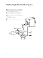
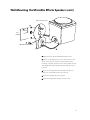
System8000
Micro Reference Series
6-Piece Speaker System with
PowerVent® Powered Subwoofer
Safety Instructions
CAUTION
RISK OF ELECTRIC SHOCK
DO NOT OPEN
WARNING: To reduce the risk of fire or electric shock, do not expose this product to
rain or moisture.
The lightning flash with arrowhead symbol, within an equilateral triangle, is intended to alert the user to the presence
of uninsulated “dangerous voltage” within the product’s enclosure that may be of sufficient magnitude to constitute a risk of electric shock to persons.
The exclamation point within an equilateral triangle is intended to alert you to the presence of important operating
and maintenance (servicing) instructions in the literature accompanying the product.
1. Read Instructions: All the safety and operating instructions should be read before the product is operated.
2. Retain Instructions: The safety and operating instructions should be retained for future reference.
3. Heed Warnings: All warnings on the product and in the
operating instructions should be adhered to.
4. Follow Instructions: All operating and other instructions
should be followed.
5. Water and Moisture: The product should not be used
near water—for example, a bathtub, washbowl, kitchen
sink, laundry tub, in a wet basement, or near a swimming
pool, etc.
6. Carts and Stands: The product should be used only with a
cart or stand that is recommended by the manufacturer. A product and cart combination should
be moved with care. Quick stops, excessive
S3125A
force, and uneven surfaces may cause the
product and cart combination to overturn.
7. Wall- or Ceiling-Mounting: The product should be
mounted to a wall or ceiling only as recommended by the
manufacturer.
8. Ventilation: The product should be situated so that its
location or position does not interfere with its proper functioning. For example, the product should not be situated
on a bed, sofa, rug, or similar surface that may obstruct
the heat sink surfaces; or placed in a built-in installation,
such as a bookcase or cabinet that may impede the flow of
air near the heat sink surfaces.
9. Heat: The product should be situated away from heat
sources, such as radiators, stoves, or other products that
produce heat.
10. Power Sources: The product should be connected to
a power supply only of the type described in the operating
instructions or as marked on the product.
2
11. Grounding or Polarization: This product may be
equipped with a polarized alternating-current line plug (a
plug having one blade wider than the other). This plug will
fit into the power outlet only one way. This is a safety feature. If you are unable to insert the plug fully into the outlet, try reversing the plug. If the plug should still fail to fit,
contact your electrician to replace your obsolete outlet.
Do not defeat the safety purpose of the polarized plug.
12. Power Cord Protection: Power supply cords should
be routed so that they are not likely to be walked on or
pinched by items placed upon or against them. Pay particular attention to cords and plugs, convenience receptacles,
and the point where they exit from the product.
13. Cleaning: The product should only be cleaned as recommended by the manufacturer.
14. Nonuse Periods: The power cord should be
unplugged from the outlet when left unused for long
periods of time.
15. Object and Liquid Entry: Care should be taken so
that objects do not fall into and liquids are not spilled into
the inside of the product.
16. Damage Requiring Service: The product should be
serviced if any of the following events occur:
A. The power supply cord or the plug has been
damaged;
B. Objects have fallen or liquid has been spilled into
the product;
C. The product has been exposed to rain;
D. The product does not appear to operate normally or
exhibits a marked change in performance; or
E. The product has been dropped or the enclosure
damaged.
17. Servicing: The user should not attempt to service the
product beyond what is described in the operating
instructions. For all other servicing, consult your dealer or
contact Boston Acoustics.
Specifications
System Frequency Response (±3dB)
44–20,000Hz
Recommended Amplifier Power
15–125 watts
Nominal Impedance
8 ohms
Sensitivity (1 watt [2.83v] at 1m)
89dB
Subwoofer Amplifier Power
65 watts continuous 4Ω; < 0.2% THD @ 50 watts, 4Ω, 30–200Hz
Bass Unit (Micro80pv subwoofer)
7" (180mm) DCD copolymer with butyl rubber surround
Midrange (Micro80x and Micro80c)
31⁄2" (89mm) copolymer with butyl rubber surround
Tweeter (Micro80x and Micro80c)
3⁄4"
Full-Range Driver (Micro80e)
31⁄2" (89mm) treated fiber
Crossover Frequency
3500Hz left & right; 4000Hz center
(19mm) dome
(Micro80x and Micro80c)
Dimensions (HxWxD)
Sub: 19 7⁄8 x 10 x 10" (505 x 250 x 250mm)
Sats: 67⁄8 x 41⁄4 x 53⁄4" (175 x 108 x 146mm)
Center: 43⁄8 x 8 x 51⁄8" (111 x 200 x 129mm)
Effects: 41⁄4 x 41⁄8 x 41⁄2" (110 x 105 x 121mm)
Weight
Subwoofer: 25 lbs (12kg); Satellites: 4 lbs ea. (2kg);
Center: 4 lbs (2kg); Effects: 2lbs (1kg)
Finish
Subwoofer, Satellites, and Effects: Black or White; Center: Black
Description
The Boston Acoustics System8000 home theater system delivers powerful performance for movies and music from small
speakers that virtually disappear in your listening room. A potent 65-watt PowerVent ® subwoofer produces exciting bass
and special effects. The two Micro80x left/right satellites and Micro80c center channel speaker use the same drivers,
creating a perfect sonic match across the front stage. Each speaker houses a Boston-built, high-power, 31⁄2" (89mm)
midrange driver and our 3⁄4" (19mm) wide-dispersion dome tweeter to provide articulate dialog and lifelike imaging.
Completing the system are two compact Micro80e rear effects speakers, for realistic, three-dimensional cinema sound.
The front satellites and rear effects speakers include wall-mount brackets for complete placement flexibility.
The key to System8000’s powerful performance is the subwoofer’s high-current amplifier and 7" (180mm) DCD™ (Deep
Channel Design) bass unit in a two-chamber bandpass enclosure. Built in Boston’s state-of-the-art production facility, this
long-throw driver was optimized using Finite Element Analysis computer modeling, giving it tremendous excursion for
exceptionally powerful bass. The subwoofer amplifier features active equalization, extending the system’s bass response
down to 45Hz. The down-firing ports further strengthen the deep bass response by coupling the subwoofer’s output to the
floor, and are smoothly flared to eliminate audible turbulence.
The Micro80x satellites and Micro80c center channel are two-way speakers for wide-range response and a seamless blend
with the subwoofer. They feature MagnaGuard® magnetic shielding to prevent television picture distortion.
For user convenience, the subwoofer features auto turn on/turn off circuitry that turns the subwoofer amplifier on automatically when a signal is sensed, and turns it off 15 minutes after the last signal has been received.
3
How to Wire Your Speakers
You need to wire your speakers correctly to obtain the best sound quality and the proper image.
Wiring should just take a few minutes, but it’s important to do it carefully, since incorrect wiring
(such as reversed connections) can result in a poor soundstage or poor bass.
We recommend using 18-gauge or larger speaker wire for runs up to 25 feet (8m), and thicker
16-gauge or larger for longer runs. Strip 1⁄ 2" (12mm) of insulation off the ends of each speaker
cable to expose the two conductors and tightly twist the wire strands. Maintain consistency of the
+ (red) and – (black) connections by using the markings on the wire.
IMPORTANT: Typically, one side of the wire is smooth. Connect
this side to the – (black) connection. The other side has a rib or
stripe. Connect this to the + (red) connection.
Micro80x Satellites and Micro80c Center Channel
Using the five-way binding posts: The binding posts permit easy connection to banana plugs,
pins, spade lugs, and bare wire. The metal surfaces are plated with 24K gold to prevent corrosion.
Insert the wire in the hole
and tighten.
Micro80pv Subwoofer and
Micro80e Effects Speaker
Push down the buttons and insert the wire
where shown. Be sure to connect + to
+ (red) and – to – (black).
4
To connect two wires to one terminal, first twist
them together. Then insert the wire in the hole
and tighten.
Speaker level input
L
R
Connecting the System8000
Speaker-Level Connections
The simplest way to wire the Micro80p is via speaker connections. Wired in this way, the subwoofer
(Micro80pv) does not present any additional load to your amplifier. There are three ways to wire the
subwoofer to your speaker connections; each way produces the same result. You may want to use
long wires to the subwoofer at first, so you may experiment with placement.
As a general rule, it is best to keep the total length of wire between the amplifier and Micro80x
satellites as short as possible. The subwoofer, on the other hand, is not sensitive to wire length.
Be sure to connect + to + (positive) and – to – (negative) by using the markings on the wire.
WARNING: To reduce the risk of electrical shock, always switch off the system and the amplifier
and/or receiver when making connections to the system and speakers.
Dolby® Pro Logic® Systems
The subwoofer and front satellites should be wired to connections for the front left and right
speakers. Even though the System8000 has a separate subwoofer, when you use speaker-level
connections, the two Micro80x satellites and Micro80pv subwoofer look to your receiver like a pair
of conventional large speakers. Set the center channel mode on your receiver to “NORMAL.”
This will send all the bass to the subwoofer.
Dolby® Digital Systems
The subwoofer and front satellites should be wired to connections for the front left and right
speakers. Even though the System8000 has a separate subwoofer, when you use speaker-level
connections, the two Micro80x satellites and Micro80pv subwoofer look to your receiver like a pair
of conventional large speakers. On your receiver’s setup menu, set the front left/right speaker
mode to “LARGE.” Choose “SUBWOOFER-NO.” Set the center channel and surround speaker
modes to “SMALL.” This sends all the bass to the front left and right channels, where it will be
reproduced by the System8000’s subwoofer.
5
Connecting the System8000 (cont.)
Speaker-Level Connections (cont.)
Option 1: Connect the
Receiver
speaker terminals on the
Micro80pv Subwoofer
Micro80pv to the left and
Line in
right speaker outputs
of your receiver. Use the
Left
Surround
speakers
Right
Center
speaker
Left
Main
speakers
Right
same speaker outputs
L
R
Speaker level in
that drive the Micro80x
satellites. Do not
connect the Micro80pv
to any other speaker
outputs that may be on
Left Micro80e
Right Micro80e
your receiver.
IMPORTANT: When
Left Micro80x
Right Micro80x
making connections, be
Micro80c
sure to connect + to +
(positive) and – to – (negative).
Alternative options: In some cases, you may find it easier to use one of the following alternative
wiring plans. The resulting sound will be the same.
Option 2: Connect the
Receiver
speaker terminals on
Micro80pv Subwoofer
the Micro80pv to the left
Line in
and right main (or front)
speaker outputs of your
Left
Surround
speakers
Right
Center
speaker
Left
Main
speakers
Right
L
receiver and to the
Micro80x satellites.
Left Micro80e
Right Micro80e
Right Micro80x
Micro80c
6
R
Speaker level in
Left Micro80x
Connecting the System8000 (cont.)
Speaker-Level Connections (cont.)
Alternative options (cont.): In some cases, you may find it easier to use one of the following
alternative wiring plans. The resulting sound will be the same.
Micro80pv Subwoofer
Receiver
Option 3: Connect
the speaker terminals
Line in
Speaker level in
L
R
on the Micro80pv to
the terminals on the
Left
Surround
speakers
Right
Center
speaker
Left
Main
speakers
Right
Micro80x satellites.
Left Micro80e
Right Micro80e
Right Micro80x
Micro80c
Left Micro80x
Testing the Connections
A simple listening test will tell you if your Micro80x satellites are connected properly. Place the
satellites face to face, with about an inch (25mm) between them. While listening to music, reverse
the connections at one speaker only. You’ll hear a dramatic change in sound. The connection that
yields the fuller and louder sound is the correct one.
After checking the satellites, you can perform this same test with the subwoofer by reversing the
speaker wires at one of its two pairs of terminal connectors. If the bass output is reduced, then the
original connections were correct.
7
Dolby Pro Logic and Dolby Digital
Line-Level System Connection
Using the line-level connection to the Micro80pv subwoofer generally results in a cleaner system
sound, since the receiver no longer has to reproduce the difficult low bass information that can push
it into audible distortion (also known as clipping).
Dolby Pro Logic Systems
Use an RCA cable (not included) to connect your receiver’s Sub out jack to the Line in jack on the
Micro80pv, as shown below.
Set the center and surround channel modes to “NORMAL.” This will send all the bass to
the subwoofer.
Micro80pv Subwoofer
Receiver
Sub out
Left
Surround
speakers
Left Micro80e
Right
Center
speaker
Line in
Left
Main
speakers
Right Micro80e
Left Micro80x
Micro80c
8
Right
Right Micro80x
L
R
Speaker level in
Dolby Pro Logic and Dolby Digital
Line-Level System Connection (cont.)
Dolby Digital Systems
If your receiver or processor gives you a choice of subwoofer low-pass crossover settings, select one
around 120Hz. This will result in the smoothest overall system response, since the lower response
limit of the Micro80x satellite and Micro80c center channel is 120Hz.
Select “SMALL” for the front left/right speakers, the center channel speaker, and the surround speakers on your receiver’s set-up menu. Select “SUBWOOFER-YES” on your receiver’s setup menu. Use
the wiring diagram shown on page 8.
If your Dolby Digital receiver has a fixed (nonadjustable) subwoofer low-pass crossover setting
below 100Hz, you may find the system sounds better when wired with both speaker wire and
line-level connections to the subwoofer, as shown below.
Select “SMALL” for the front left/right speakers, the center channel speaker, and the surround speakers on your receiver’s setup menu. Select “SUBWOOFER-YES” on your receiver’s setup menu.
Receiver
Sub out
Line in
Left
Surround
speakers
Right
Center
speaker
Left
Main
speakers
Right
L
R
Speaker level in
Micro80pv Subwoofer
Left Micro80e
Right Micro80e
Left Micro80x
Right Micro80x
Micro80c
9
Micro80pv Subwoofer Controls
Volume: Adjusts the sound level of the subwoofer. If you are using the speaker-level connections,
begin with a setting at about the 10:00 o’clock position. When using the line-level connections,
begin with a setting around 11:00 o’clock. Your actual setting may vary due to personal taste, program material, and subwoofer placement.
NOTE: Power is always supplied to the subwoofer electronics unless it is unplugged. The auto-on
circuitry only activates or deactivates the power amplifier.
BostonAcoustics
Micro80pv Powered Audio/Video Subwoofer
Power
Volume
Line level in
Speaker level in
L
10
R
How to Place Your Speakers
Room placement is one of
the most important factors
Center channel
flush with
front of TV
for sound quality. Taking
a few minutes to try differ-
Left satellite
1-3 ft. (0.3-1m)
Right satellite
1-3 ft. (0.3-1m)
Subwoofer in
corner for maximum
bass output
ent placements ensures
that your speakers will
Place the surround
speakers beside or
behind the listeners,
above ear level
sound best in your
listening environment.
5-9 ft.
(1.5-3m)
The surround speakers may
be mounted near the floor
facing up, beside or behind
the listening position
Micro80x Satellite Placement
We recommend that you center the two satellites in front of your favorite listening position, about
6 to 12 feet (2-4m) apart, and near ear level when you are in a seated position.
The satellites may be hung from a wall with the included keyhole bracket or the optional MRB
pedestal stand/wall-mount bracket. (See page 15 for more details.) A threaded insert on the back
of each satellite allows for use with many brands of satellite floor stands. Check with your dealer
for more details.
Micro80e Effects Speaker Placement
The Micro80e effects speaker provides the ambient soundfield essential for realistic cinema sound.
To achieve the best surround sound, place the Micro80e so its sound is diffused around the listening area. They may be placed above ear level facing out or below ear level, facing up. No matter
how the speakers are placed, avoid aiming them directly at the listeners.
Micro80c Center Channel Placement
This low-profile, dedicated speaker is designed to rest unobtrusively on top of your television.
The speaker’s MagnaGuard® magnetic shielding allows this placement without TV interference.
The front of the speaker should be flush with the front of the television. The speaker includes
self-adhesive rubber feet to protect the TV’s finish and to prevent vibration.
11
Wall-Mounting the Micro80e Effects Speakers
Drill two 7⁄ 16" (11mm) holes for toggle wings. If mounting on a
1
surface other than drywall, consult a knowledgeable installer
about the proper hardware to use on your wall.
If you are running speaker wire behind the wall, drill a 1⁄ 2"
2
(12mm) hole 3⁄ 4" (19mm) below the top toggle wing hole.
Attach bracket to wall with machine screws and toggle wings,
3
as shown below.
4
Connect speaker wire to speaker.
5
Attach speaker to bracket with flathead machine screw.
4
1
2
115/32"
(37mm)
Drill 7/16" (11mm) holes
for toggle wings
3
3
/4"
(19mm)
6–32 x 2"
machine screws
5
flathead machine screw
12
Wall-Mounting the Micro80e Effects Speakers (cont.)
#9 x 1" wood screws
2
3 1"
(25mm)
25/32"
(55mm)
1
flathead machine screw
5
4
1
Attach bracket to speaker with flathead machine screw.
2
Drill two 1⁄ 8" (3mm) pilot holes for wood screws, then mount
screws. Leave about 1⁄ 8" (3mm) of screw thread exposed. If
mounting on drywall, use plastic anchors (not included). Consult
a knowledgeable installer about the proper hardware to use on
your wall.
3
If you are running speaker wire behind the wall, drill a 1⁄ 2"
(12mm) hole 1" (25mm) below the top screw hole.
4
Connect the speaker wire to the speaker.
5
Slip the bracket/speaker assembly onto the screws.
13
Setting Up Your Home Theater System
Volume Levels: To obtain the best home theater effect, match the sound levels of each speaker.
Home theater systems include a test signal that simplifies this level matching. Refer to the instructions provided with your surround-sound electronics.
Center Channel Mode: Generally, with all surround systems, including Dolby® Pro Logic® and
Dolby® Digital, the center channel mode should be set to “NORMAL” or “SMALL.” This setting
diverts low bass to the subwoofer and results in the greatest total system bass output. The
“PHANTOM” setting, which presumes you do not have a center channel speaker, should not be used.
Surround Channel Mode: If your electronics have a surround channel mode, it should also be
set to “NORMAL” or “SMALL.” This setting will divert any low bass in the surround channels to
the subwoofer.
14
Wall-Mounting Your Micro80x Satellites
The Micro80x satellite may be wall-mounted using the included keyhole bracket:
1
Install a #8 or #10 mounting screw on
the wall (not supplied–consult a knowledgeable installer regarding the proper
1
hardware to use on your wall surface).
2
Attach the bracket to the back of
the speaker with the machine screw
and acorn nut as shown.
3
If you are running wires behind the
3
wall, make a 3⁄ 8" (9.5mm) wire hole,
13⁄4" (44mm) below the mounting
screw for the wire.
2
An optional pedestal shelf stand/wall-mount
bracket (Model MRB) is available for the
Micro80x that provides greater positioning
The speaker may be angled for opti-
flexibility. For more information, contact your
mum coverage of the listening area.
dealer or Boston Acoustics directly.
Troubleshooting
Subwoofer does not make sound
1. Check to ensure the subwoofer’s AC power cord is properly plugged in. If the outlet being used
is controlled by a switch, make sure the switch is on.
2. If the power cord is properly attached but the pilot light does not illuminate, the AC fuse may be
blown. If necessary, replace the fuse with a same-type fuse or consult a service technician.
Listening Levels and Power Handling
The power recommendation for the speaker assumes the amplifier is not overdriven, which, over a
long period, can damage even our rugged speakers. If you hear a harsh, gritty noise, turn down the
volume control. Prolonged or repeated operation with a distorted signal from the amplifier can
cause damage to the speakers, which is not covered by the warranty.
15
Limited Warranty
For five years from the date of purchase, Boston Acoustics will repair for the original owner any
defect in materials or workmanship that occurs in the normal use of the Micro80x satellites, Micro80c
center channel speaker, and Micro80e effects speakers, without charge for parts and labor.
For one year from the date of purchase, Boston Acoustics will repair for the original owner any
defect in materials or workmanship that occurs in normal use of the Micro80pv powered subwoofer, without charge for parts and labor.
Your responsibilities are to use the system according to the instructions supplied, to provide safe
and secure transportation to an authorized Boston Acoustics service representative, and to present
proof of purchase in the form of your sales slip when requesting service.
Excluded from this warranty is damage that results from abuse, misuse, accidents, shipping, or repairs
or modifications by anyone other than an authorized Boston Acoustics service representative.
This warranty is void if the serial number has been removed or defaced.
This warranty gives you specific legal rights, and you may also have other rights which vary from
state to state.
If Service Seems Necessary
First, contact the dealer from whom you purchased the System8000. If that is not possible, write to:
Boston Acoustics, Inc. 300 Jubilee Drive Peabody, MA 01960 U.S.A.
We will promptly advise you of what action to take. If it is necessary to return your speaker to the
factory, please ship it prepaid. After it has been repaired, we will return it freight prepaid in the
U.S. and Canada.
300 Jubilee Drive
Peabody, MA 01960 U.S.A.
978.538.5000
DCD, PowerVent, MagnaGuard, Boston, and
Boston Acoustics are registered trademarks of
Boston Acoustics, Inc. Dolby and Dolby Pro Logic
are registered trademarks of Dolby Laboratories
Licensing Corporation.
© 1998 Boston Acoustics, Inc. All rights reserved.
Specifications subject to change without notice.
42-882-0