1
VSX41
Video Switcher
Operation Manual
®
Biamp Systems, 10074 S.W. Arctic Drive, Beaverton, Oregon 97005 U.S.A. (503) 641-7287 http://www.biamp.com
an affiliate of Rauland-Borg Corp.
blank
print update
Dec 9/99
VSX41
INTRODUCTION
TABLE OF CONTENTS
Front Panel
pg. 2
Rear Panel
pg. 3
Remote Control
pg. 4
Options
pg. 6
Applications
pg. 7
Block Diagram
pg. 10
Specifications
pg. 11
Warranty
®
The ADVANTAGE VSX41 Video Switcher provides four video inputs and one
video output, with source selection and remote control functions. Passive
switching allows the VSX41 to be used as either a switcher or router, and for
either video or audio signals. The VSX41 is designed to operate independently
or in conjunction with other ADVANTAGE products, such as the SPM412e
Stereo Preamp/Mixer. The VSX41 Video Switcher is ideally suited for
applications such as sports bars, meeting rooms, class rooms, auditoriums,
multi-media presentation, and tele-conferencing. The VSX41 is versatile, costeffective, easy to install, and carries a five-year warranty.
VSX41 features include:
♦ four video inputs, each with both BNC and RCA connectors
♦ one video output, with both BNC and RCA connectors
♦ front panel push-buttons select from the four input sources
♦ front panel infrared receiver for remote control of switching
♦ two rear panel ports for infrared and/or wall-mount controls
♦ ’remote output’ for control of other ADVANTAGE products
♦ ’logic inputs’ for control from other ADVANTAGE products
♦ ’remote translator’ for interface to third-party controllers
♦ compatible with most AMX & CRESTRON controllers
®
®
♦ ’switching’ function assigns 1-of-4 inputs to a single output
♦ ’routing’ function assigns single input to 1-of-4 outputs
♦ selectable ’back-termination’ for video or audio applications
♦ dry contact relay switching for complete ground isolation
♦ covered by Five-Year ’Gold Seal’ Warranty
♦ UL listed power source
AMX is a registered trademark of AMX Corporation.
CRESTRON is a registered trademark of CRESTRON Electronics, Inc.
1
FRONT PANEL
ADVANTAGE VSX41
channel select
Video Switcher
Error
1
2
3
IR
on
4
(1)
(2) (3) (4)
(5)
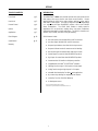
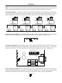
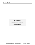
(1) Channel Select 1~4: These momentary push-buttons select which of the four input signals is sent to the output. To select a desired
input, press the corresponding push-button (see Remote Control on pages 4 & 5). The adjacent LED indicator will light, indicating the
selection. Only one input can be selected at a time. If power is lost or turned off, Channel Select reverts to Input 1 when power returns.
The VSX41 may be used as a "router", with a single input signal being switched to one of four outputs (see Applications on page 9). The
VSX41 may be used with either video or audio signals. From the factory, Inputs 1~4 have ’back-termination’ of 3.9k ohms, which is
appropriate for most applications. However, internal jumper straps allow selection of 75 ohm ’back-termination’, which is required only for
specific video applications (see Options on page 6).
(2) Error: This red LED indicates when unusable information is received via remote control (see Remote Control on page 4 & 5). Errors
in transmission/reception of remote control commands, or improperly connected controls, will cause the Error indicator to light.
(3) IR: This red LED indicates when information is received via remote control. If the IR and Error indicators light simultaneously, this may
be an indication of improper installation. Check the location and wiring of all remote controls.
(4) Internal Infrared Receiver: This green infrared detector receives commands from optional hand-held Infrared Transmitters (see
Remote Control on page 4). A transmitter will work up to 30 feet from the receiver. For best results, there should be an unobstructed lineof-sight from the transmitter to receiver. When infrared commands are received, the IR indicator will light. If the IR and Error indicators
light simultaneously, this may be an indication of improper installation. The Internal Infrared Receiver should not be located in direct
sunlight, or pointed directly at fluorescent lighting. An internal jumper strap is provided to allow the user to bypass the Internal Infrared
Receiver (see Options on page 6).
(5) Power: When the Power switch is turned on, the red "On" LED will light and Channel Select will revert to Input 1.
2
REAR PANEL
BIAMP SYSTEMS
remote
output
PORTLAND,OREGON
an affiliate of
Rauland-Borg Corp
~
27V
15 watts
50/60 Hz
class 2
wiring
(7)
logic inputs
(6)
remote
translator
remote 2
remote 1
output
input 4
input 3
input 2
input 1
gnd IR2 IR3 gnd low high gnd IR2 IR3 gnd IR2 IR3
(5)
(4)
(3)
(2)
(1)
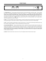
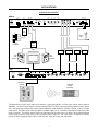
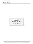
(1) Inputs 1~4: Each input is provided on both BNC and RCA type connectors, which are wired in parallel. Inputs 1~4 will accept any
video signals from cameras, VCRs, laser-discs, cable, satellite, etc. The VSX41 may instead be used as an audio switcher, with Inputs
1~4 accepting any mono line level audio signals from mixers, tapes, CDs, VCRs, cable, satellite, etc. Connections for audio signals are
typically unbalanced, wired with (+) to tip and (ground) to sleeve. However, if all audio signals to be connected are balanced, they may be
wired with (+) to tip and (-) to sleeve (the input/output grounds are connected directly, bypassing the VSX41). The VSX41 may also be
used as a 1-in/4-out video (or audio) "router", with a single input being switched to one of four outputs (see Applications on page 9). From
the factory, Inputs 1~4 have ’back-termination’ of 3.9k ohms, which is appropriate for most applications. However, internal jumpers allow
selection of 75 ohm ’back-termination’, which is required only for specific video applications (see Options on page 6).
(2) Output: The Output is provided on both BNC and RCA type connectors, which are wired in parallel. The VSX41 is a passive
switching device (using dry contact relays), and will provide an output signal identical to the selected input signal. The VSX41 does not
provide any processing, synchronization, or amplification of signals. The VSX41 may instead be used as an audio switcher, with Inputs
1~4 accepting (and the Output providing) mono line level audio signals. Connections for audio signals are typically unbalanced, wired with
(+) to tip and (ground) to sleeve. However, if all audio signals to be connected are balanced, they may be wired with (+) to tip and (-) to
sleeve (the input/output grounds are connected directly, bypassing the VSX41). The VSX41 may also be used as a 1-in/4-out video (or
audio) "router", with a single input being switched to one of four outputs. This is accomplished simply by connecting to the VSX41 Output
as if it were a single input. Inputs 1~4 are then utilized as the four possible outputs (see Applications on page 9).
(3) Remote 1 & Remote 2: These screw terminals are for connection of optional remote controls (see Remote Control on pages 4 & 5).
Including the Internal Infrared Receiver, the Remote Translator (4), and the Logic Inputs (6), these terminals allow remote control from up
to five locations. Optional remote controls may be wired up to 2000 feet from the VSX41, using 2-conductor shielded cable.
®
®
(4) Remote Translator: These screw terminals are for connection of certain third-party controllers (such as AMX and CRESTRON ),
which generate "carrier-stripped" remote control signals. Two remote translator inputs are provided. The Low terminal being used for
controllers which produce a "low" output level (-15VDC ~ +2VDC) when idle. The High terminal is for controllers which produce a "high"
output level (+2VDC ~ +15VDC) when idle. The third-party controller must be programmed to output a bitstream in the Biamp format
(contact the controller manufacturer to determine if their device driver library currently supports the Biamp format).
®
(5) Remote Output: These screw terminals are for connection to other ADVANTAGE products having similar remote control capabilities
(such as the SPM412e, SPM522D, DRC4+4, PMX84, and EQ282M). Remote Output combines the commands from VSX41 front panel
switches, remote controls, & logic inputs, for simultaneous remote control of additional devices (see Applications on page 7).
(6) Logic Inputs: This 9-pin Subminiature D (female) connector provides four logic inputs and their related ground. Logic Inputs allow
remote control of the VSX41 Channel Select switching function via external logic output circuits, contact closures, or active driver circuits
(see Remote Control on page 5). Remote control via logic output circuits is possible from other ADVANTAGE products, such as the AGII,
DRC4+4, and PMX84 (see Applications on page 8). Remote control via contact closures is possible using switches, relays, or certain thirdparty controllers (see Applications on page 9). The Logic Inputs may also be remotely controlled via active driver circuits (such as a TTL or
RS-232 output). Logic Inputs also include a "priority switching" scheme and internal jumpers for input pin assignment.
(7) AC Power Cord: The external power transformer provides 27 Volts AC to the VSX41, and is detachable via a 5-pin DIN connector.
The VSX41 has two internal 1 Amp Normal-Blow (1A NB) fuses. If fuses should require replacement, use same fuse value and type only.
3
REMOTE CONTROL
An infrared receiver is provided on the VSX41 front panel, however, infrared and wall-mount remote control
is optional. This allows the user to select only the type and quantity of controls necessary for a particular
application. Remote controls affect VSX41 Channel Select switching, as well as functions on other
®
ADVANTAGE products that might be connected to the VSX41. Remote controls may be added at any
time, and do not require the VSX41 to be modified, opened, or removed from a rack. There are four
remote control devices: a hand-held Infrared Transmitter, an Infrared Receiver unit, a wall-mount pushbutton Controller with status indicators & infrared detector, and a Remote Interface Kit for building custom
control panels. Remote control of the VSX41 is also possible via third-party controllers and Logic Inputs.
Infrared Transmitter (Biamp #909-0060-00): The transmitter is a hand-held remote control, which
transmits infrared codes unique to Biamp. Therefore, the Transmitter should not affect any other infrared
controlled equipment (such as TVs or VCRs). Likewise, other infrared controllers will not provide proper
control of Biamp equipment. The transmitter requires two AAA batteries, which are included with the unit
(user installed). The transmitter has twenty-eight buttons, only four of which control functions on the
VSX41. Channel Select 1~4 buttons provide the same function as Channel Select 1~4 buttons on the
VSX41 front panel. The remaining buttons on the transmitter may be used to control other ADVANTAGE
products, which are connected to the VSX41 Remote Output. When used in this way, VSX41 Channel
Select functions may be assigned to the next row of buttons, to avoid conflict with the other products (see
Options on page 6). For best results, there should be an unobstructed line-of-sight from transmitter to
receiver. The transmitter will operate up to 30 feet from a receiver. When infrared information is
transmitted to a receiver, the IR LED indicator on the VSX41 front panel will light. The transmitter is
labelled for use with the VSX41 and SPM412e.
External Infrared Receiver (Biamp #909-0030-00): The receiver consists of a black plastic box, which
contains an infrared photo detector, an LED indicator, and three screw terminals. To install the receiver,
first take off the front cover by removing the four screws. Mount the receiver to wall or other surface, using
the two screw holes on the back cover (screws not included). The receiver should not be mounted in direct
sunlight, or pointed directly at fluorescent lighting. For best results, there should be an unobstructed lineof-sight from transmitter to receiver. The receiver may be wired up to 2000 feet from the VSX41, using 2conductor shielded cable (not included). Route the cable through the access hole on the bottom of the
receiver. The three screw terminals inside the receiver ("GND", "IR2", & "IR3") directly correspond to the
Remote 1 and Remote 2 terminals on rear panel of the VSX41. Connect the cable shield to the "GND"
terminal at each end. Use the two conductors to connect "IR2" to "IR2" and "IR3" to "IR3". Replace the
receiver front cover. When the VSX41 is turned on, power is delivered to the receiver. The LED indicator
inside the receiver (and the IR LED indicator on the VSX41 front panel) will light whenever infrared
information is detected. NOTE: The Infrared Receiver includes a "Remote Translator", which allows
remote control via third-party controllers (instructions included with receiver).
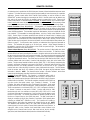
Controller (Biamp #909-0128-00): The Controller is a ‘hard-wired’ control, which is
powered by the VSX41. There are no batteries to wear out, and it is not easily lost or
stolen. The Controller may be wired up to 2000 feet from the VSX41, using 2-conductor
shielded cable (not included). The Controller overrides commands to the VSX41 from
any other source (front panel controls, Logic, Translator, & Remote). To install
Controller, first remove mounting box from circuit board & front panel. Route cable
through ‘knock-out’ hole on rear of mounting box. Install mounting box in wall or panel.
1
Three screw terminals on circuit board (‘GND’, ‘IR2’, & ‘IR3’) correspond to ‘Remote 1’
or ‘Remote 2’ terminals on rear panel of VSX41. Connect cable shield to ‘GND’
2
terminals at each end. Use conductors to connect ‘IR2’ to ‘IR2’ & ‘IR3’ to ‘IR3’. Install
3
circuit board & front panel on mounting box. Only four of the Controller buttons control
functions on the VSX41. The Channel Select buttons & indicators provide the same
4
functions as Channel Select on the VSX41 front panel. The Main Level buttons &
CHANNEL SELECT
display do not affect the VSX41 (the Controller is used with a VSX41 primarily when
®
controlling an ADVANTAGE SPM412e as well). The Controller also includes an
infrared detector, which allows it to operate as an Infrared Receiver as well. NOTE:
Two additional screw terminals (‘GND’ & ‘KEY SWI’) allow an external key-switch (or
contact-closure) to ‘lock-out’ control of Channel Select (and/or Main Level) functions. A
4-gang DIP switch on the Controller circuit board allows custom functions to be
assigned, such as Channel Select ‘lock-out’, Main Level ‘lock-out’, key-lock normallyopen/closed, and infrared detector defeat (instructions included with Controller).
4
1
CHANNEL SELECT
2
3
4
MUTE
VOL
VOL
ADVANTAGE SPM412e
MAIN
LEVEL
InfraRed Receiver
SPM412e Controller
max
MUTE
min
MAIN LEVEL
REMOTE CONTROL
Remote Interface Kit (Biamp #909-0041-00): The Remote Interface Kit allows the user to create a customized control panel, using his
own switches, enclosure, and panel. It can provide up to 40 buttons (12 more than standard remote controls), which are support by some
®
other ADVANTAGE products. The VSX41 itself only supports 4 buttons (Channel Select), but it will also pass commands on to other
Advantage products which have been connected to the Remote Output (see Applications on page 7). The Remote Interface Kit is a tested
circuit board assembly, which includes two wiring harnesses. The circuit board connects to the VSX41 in exactly the same way the
External Infrared Receiver does, using 2-conductor shielded cable (not included), and may be wired up to 2000 feet from the VSX41. The
three screw terminals on the circuit board ("GND", "IR2", & "IR3") directly correspond to the Remote 1 & Remote 2 terminals on the rear
panel of the VSX41. Connect the cable shield to the "GND" terminal at each end. Use the two conductors to connect "IR2" to "IR2" and
"IR3" to "IR3". When the VSX41 is turned on, power is delivered to the circuit board. The circuit board is 2.27"W by 2.65"H, with four
mounting holes (2" centers) and #6 mounting hardware provided. Complete instructions are included with the Remote Interface Kit.
Logic Inputs: The 9-pin Subminiature D (female) connector on the rear panel of the VSX41 provides four logic inputs and their related
ground. Logic Inputs allow remote control of the VSX41 Channel Select switching function via external logic output circuits, contact
closures, or active driver circuits. When nothing is connected to a Logic Input, an internal pull-up resistor keeps it at a "high" idle state.
The Logic Input is activated when its input goes "low" (less than +2VDC). A Logic Input is controlled in one of three ways: 1) Use an NPN
style "open collector" logic output from an external device (such as an ADVANTAGE AGII or DRC4+4) to short the Logic Input to ground.
2) Use a switch, relay, or other contact closure (such as from a third-party controller) to short the Logic Input to ground. 3) Use an active
TTL or RS-232 output driver circuit (such as from a third-party controller) to actively drive the Logic Input to a "high" or "low" state. Multiple
logic outputs or contact closures may be wired in parallel to a single Logic Input. Logic outputs and contact closures should be rated for at
least 5 Volt / 1 mA operation. Low-current / dry-contact closures are recommended for reliability. Active output driver circuits should not
exceed a signal range of -15VDC to +15VDC, and should have a minimum pulse width of 50 milli-seconds. Logic Input impedances are
approximately 1k ohms for negative voltages, and approximately 10k ohms for positive voltages. Maximum recommended cable length for
Logic Inputs is 10 feet. The VSX41 Logic Inputs include a "priority switching" scheme (Logic Input 1 overrides Logic Inputs 2~4, Logic
Input 2 overrides Logic Inputs 3 & 4, and Logic Input 3 overrides Logic Input 4). For example, if Logic Input 2 is turned on (Channel 2
selected) and then Logic Input 1 is also turned on, the VSX41 will switch to Channel 1. However, if Logic Input 2 is turned on (Channel 2
selected) and then Logic Input 3 is also turned on, the VSX41 will not switch channels. This "priority switching" also helps limit the amount
of unnecessary switching in video-follow-audio applications. Logic Input #4 may be hard-wired to ground, designating Input 4 as the
default when no other input is selected (see Applications on page 8). The Logic Input "priority switching" scheme will be overridden by
commands received from other remote controls. When controlling the VSX41 via logic outputs from an AGII or DRC4+4, internal jumper
straps are provided which assign the VSX41 Logic Inputs to the corresponding pins for those products (see Options on page 6). From the
factory, Logic Inputs 1~4 are assigned to pins 1~4, with pin 5 being ground.
5 4 3 2 1
9 8 7 6
logic inputs
Third-Party Controllers: The VSX41 may be remotely controlled by third-party controllers in three ways: 1) Connect "carrier stripped"
remote control signals to the VSX41 Remote Translator (see Rear Panel on page 3). 2) Connect contact closures, logic output circuits, or
active TTL / RS-232 driver circuits to the VSX41 Logic Inputs (see Logic Inputs above). 3) Apply "infrared transmitter" signals to the
VSX41 Internal or External Infrared Receivers. The third-party controller must be programmed to output a bitstream in the Biamp format
(contact the controller manufacturer to determine if their device driver library currently supports the Biamp format).
5
OPTIONS
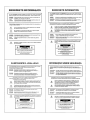
NOTE: To access internal jumper options: 1) disconnect the unit from AC power 2) remove the top panel 3) lay the unit with the front
panel facing away 4) using needle-nose pliers, move the desired jumper straps as described below 5) replace the top panel.
75 Ohm Back-Termination: From the factory, Inputs 1~4 have 3.9k ohm ’back-termination’, which is appropriate for most applications.
However, internal jumpers allow selection of 75 ohm ’back-termination’, which is required only for specific video applications. To select 75
ohm ’back-termination’, move the Input 1~4 jumper straps (J102~J402) down one pin, to the "75 OHMS" position (see diagram below).
J402
J302
J202
J102
HI-Z
HI-Z
HI-Z
HI-Z
75
OHMS
75
OHMS
75
OHMS
75
OHMS
INPUT 4
RCA
jack
INPUT 3
BNC
jack
RCA
jack
INPUT 2
BNC
jack
INPUT 1
BNC
jack
RCA
jack
RCA
jack
BNC
jack
Internal Infrared Receiver Bypass: An internal jumper allows the Internal Infrared Receiver to be bypassed. To bypass the Internal
Infrared Receiver, move the "INTERNAL RECV" jumper strap (J3) left one pin, to the "OUT" position (see diagram below).
J3
ERROR
IR
ON
IR1
OUT IN
INTERNAL RECV
®
Logic Inputs Pin Assignments: When controlling the VSX41 via logic outputs from an ADVANTAGE AGII or DRC4+4, internal jumpers
allow VSX41 Logic Inputs to be assigned to corresponding pins for those products (refer to AGII & DRC4+4 manuals). To assign Logic
Input pins, move the "SOURCE SELECT" jumper straps (J2) to the desired Logic Input Pin Number positions (see diagram below).
SOURCE SELECT
1
9 48 37 6 26 1
LOGIC INPUT PIN NUMBER
J1
C2
2 2
F2
C1
J3
OUT IN
INTERNAL RECV
IR1
IR
3
J2
4
ERROR
F1
ON
Remote Control Button Assignment: When using Remote Output to control additional ADVANTAGE products, VSX41 Channel Select
functions may be assigned to the next row of buttons, to avoid conflict with the other products. To assign Channel Select to the second
row of remote control buttons, move the "OPTION Z" jumper strap (J4) down one pin, to the "OFF" position (see diagram below).
J4
ON
OFF
OPTION
z
6
APPLICATIONS
Audio/Video Source Selection
SPM412e
zone
output
IR3
xlate
gnd
IR2
remote
~
27V
50/60 Hz
main output
L
R
limit
threshold
stereo
mono
15 watts
class 2 wiring
level
4
tone
defeat
main
output
off
on
level
3
0
10
level
1
level
2
0
0
0
10
10
10
phantom
power
off
on
BIAMP SYSTEMS, Portland, Oregon
limit
mic / line input
4
an affiliate of Rauland-Borg Corp.
3
inputs
signal
present
out
in
1
2
mute
pad
trim
+10
mono
zone
amp.
paging
mic
audio sources
mono
zone
speakers
stereo
main
amp.
video
monitor/projection
misc.
right
main
speaker
VCR
cable
satellite
left
main
speaker
video sources
VSX41
BIAMP SYSTEMS
ADVANTAGE VSX41
Portland, Oregon
Video Switcher
remote
output
remote
translator
remote 2
remote 1
output
input 4
input 3
input 2
input 1
an affiliate of
Rauland-Borg Corp.
logic inputs
gnd IR2 IR3 gnd low high gnd IR2 IR3 gnd IR2 IR3
wall-mount
controller
hand-held
infrared
transmitter
SPM412e Controller
4
1
MUTE
min
CHANNEL SELECT
VOL
MAIN
LEVEL
ADVANTAGE SPM412e
3
MUTE
4
CHANNEL SELECT
2
3
2
VOL
max
1
MAIN LEVEL
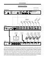
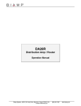
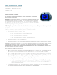
This diagram shows a VSX41 used for video source selection in a "sports bar" application. A similar system could be used for classroom
®
applications. The VSX41 Remote Output is connected to an ADVANTAGE SPM412e Remote input, allowing combined control of the two
units. Wall-mount and/or infrared remote controls provide simultaneous "audio-follow-video" switching of sources, as well as a master
volume control. The VSX41 receives video input signals from satellite, cable, VCR, etc., and sends a single output to a large-screen video
monitor or projector. The SPM412e receives stereo audio input signals from the same sources, and sends a stereo output (with remote
volume control) to the main sound system, as well as providing a mono output for a zone sound system. In addition, the SPM412e
provides an input for a paging microphone, which includes automatic "page-over" muting of the audio signals.
7
APPLICATIONS
Corporate Video Conferencing
audio feed to codec
audio feed from codec
VOICECRAFTER
-20dB
0dB
BIAMP SYSTEMS
Portland, Oregon
27 watts
class 2 wiring
an affiliate of
Rauland-Borg Corp.
setup
MADE IN U.S.A.
control
level
aux out
main out
inputs
codec
level
aux in
VOICECRAFTER
trim
trim
+10
codec out
codec in
+10
channel 2
channel 1
This device complies with Part 15 of the FCC Rules.
Operation is subject to the following two conditions:
(1) This device may not cause harmful interference,
and (2) this device must accept any interference
received, including interference that may cause
undesired operation.
Complies with Part 68, FCC Rules.
FCC Reg. No. 6RM USA-35214-BR-T
Ringer Equivalence 0.0dB
ch
(p airm
rio a
rity n m
#1 ic
pr
)
es
(p ent
rio at
rity ion
#1 mi
) c
~
27V
50/60 Hz
member mics
(priority #3)
autoONE
8
video feed
from codec
ON
7
video feed
to codec
ON
6
patch
input
ON
5
ON
4
patch
patch
input
input
ON
3
input
ON
2
pad
ungated
phantom
duck ch8
patch pre
ON
patch
input
pad
ungated
phantom
duck ch8
patch pre
ON
patch
input
pad
ungated
phantom
duck ch8
patch pre
ON
patch
input
pad
ungated
phantom
duck ch8
patch pre
outputs
patch
input
pad
ungated
phantom
duck ch8
patch pre
expansion
patch
stack in
pad
ungated
phantom
aux off
patch pre
logic
outputs
aux
slave
-12db
hp filter
last mic
aux post
15 watts
class 2 wiring ±12VDC
main
an affiliate of
Rauland-Borg Corp.
pad
ungated
phantom
duck ch8
patch pre
main patch
Portland, Oregon
DC out
pad
ungated
phantom
duck ch8
patch pre
BIAMP SYSTEMS
~
27V
50/60 Hz
1
room
member
chairman presentation
camera
camera
camera
camera
(priority #4) (priority #3) (priority #2) (priority #1)
video
monitor
VSX41
BIAMP SYSTEMS
ADVANTAGE VSX41
Portland, Oregon
Video Switcher
remote
output
remote
translator
remote 2
remote 1
output
input 4
input 3
input 2
input 1
an affiliate of
Rauland-Borg Corp.
logic inputs
gnd IR2 IR3 gnd low high gnd IR2 IR3 gnd IR2 IR3
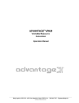
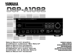
This diagram shows a VSX41 used for video source selection in a "corporate video conferencing" application. A similar system could be
®
used for "distance learning" applications. An ADVANTAGE autoONE automatic (voice-activated) mixer accepts the microphone signals.
When a microphone becomes active, a corresponding Logic Output goes on. The Logic Outputs of the autoONE are connected
(individually or in specific groups) to the Logic Inputs of the VSX41, for "video-follow-audio" switching. Therefore, the VSX41 will
automatically select the appropriate camera when some one speaks. When the "presentation" mic becomes active, the VSX41 switches to
the "presentation" camera. The "presentation" camera has priority over all other cameras. (The audio & video "presentation" signals could
instead be from a VCR or multi-media device.) The "chairman" camera has priority over the "member" & "room" cameras, and the
"member" camera has priority over the "room" camera. The "room" camera can be made to come on whenever no one is speaking, by
wiring the VSX41 Logic Input 4 directly to ground. Manual or automatic audio override can also be assigned to channel 1 of the autoONE
mixer. A VOICECRAFTER provides echo canceling and proper interface of audio signals to the video-conferencing codec.
8
APPLICATIONS
Audio Paging Router
telephone
paging
line
receptionist
paging
mic
301
enable
±12VDC
MADE IN U.S.A.
input
input
3
pad
pad
pad
phntm
input
phntm
ch 3 duck
ch 1
remote
remote
v c
ch 2
15 watts
class 2 wiring
patch
in out
patch
main out stack in
DC out
phntm
301
BIAMP SYSTEMS an affiliate of Rauland Borg Corp.
~
27V
50/60 Hz
2
1
VSX41
BIAMP SYSTEMS
ADVANTAGE VSX41
Portland, Oregon
Video Switcher
remote
translator
remote
output
remote 2
output
remote 1
input 4
input 3
input 2
input 1
an affiliate of
Rauland-Borg Corp.
logic inputs
gnd IR2 IR3 gnd low high gnd IR2 IR3 gnd IR2 IR3
remote
switches
is a registered
trademark of
Rauland-Borg
Corp
pre
out
amp
in
channel 6
trim
inal
priority
25V
compressor
max
50V
min
70V
(100V)
USE ONLY WITH
250V FUSE
auto mute
trim
on
off
priority
line
mic
max
threshold adjust
max
min
8
CAUTION:
replace with
same type
fuse.
6A - 115V
3A - 230V
channel 5
channel 4
phantom pwr
auto mute
manual mute
mute -40
level -20
phantom pwr
auto mute
manual mute
mute -40
level -20
min
inal
channel 3
phantom pwr
auto mute
manual mute
mute -40
level -20
max
trim
min
on
off
priority
line
mic
inal
channel 2
phantom pwr
auto mute
manual mute
mute -40
level -20
max
trim
min
on
off
priority
line
mic
inal
channel 1
phantom pwr
auto mute
manual mute
mute -40
level -20
max
trim
min
on
off
priority
line
mic
CH.1
inal
phantom pwr
auto mute
manual mute
mute -40
level -20
max
trim
min
on
off
priority
line
mic
nom
an affiliate of
Rauland-Borg Corp
max
rec
out
nom
com
BIAMP SYSTEMS PRECEDENCE
chime
level
line
out
nom
4
nom
direct
nom
zone #4
speakers
send/return
120watt
output
xfmr
nom
CMA60
inal
max
min
on
off
line
mic
min
remote
mute/
level
chime stacking in
+10V c gnd
+ com
+
+
com
+
com
+
com
+
com
tel
com
+
tel
com
115/230V AC 50/60 Hz 375 VA
pre
out
trim
inal
priority
25V
compressor
max
50V
min
70V
(100V)
USE ONLY WITH
250V FUSE
auto mute
on
off
priority
line
mic
max
threshold adjust
trim
min
8
CAUTION:
replace with
same type
fuse.
6A - 115V
3A - 230V
channel 5
channel 4
phantom pwr
auto mute
manual mute
mute -40
level -20
max
inal
channel 3
phantom pwr
auto mute
manual mute
mute -40
level -20
max
trim
min
on
off
priority
line
mic
inal
channel 2
phantom pwr
auto mute
manual mute
mute -40
level -20
max
trim
min
on
off
priority
line
mic
inal
channel 1
phantom pwr
auto mute
manual mute
mute -40
level -20
max
trim
min
on
off
priority
line
mic
CH.1
inal
phantom pwr
auto mute
manual mute
mute -40
level -20
max
trim
min
on
off
priority
line
mic
nom
is a registered
trademark of
Rauland-Borg
Corp
min
amp
in
channel 6
phantom pwr
auto mute
manual mute
mute -40
level -20
max
rec
out
nom
an affiliate of
Rauland-Borg Corp
chime
level
line
out
nom
4
com
nom
direct
nom
zone #3
speakers
send/return
120watt
output
xfmr
BIAMP SYSTEMS PRECEDENCE
nom
CMA60
inal
max
min
on
off
line
mic
min
remote
mute/
level
chime stacking in
+10V c gnd
+ com
+
+
com
+
com
+
com
+
com
tel
com
+
tel
com
115/230V AC 50/60 Hz 375 VA
is a registered
trademark of
Rauland-Borg
Corp
pre
out
amp
in
channel 6
channel 5
channel 4
channel 3
channel 2
phantom pwr
auto mute
manual mute
mute -40
level -20
phantom pwr
auto mute
manual mute
mute -40
level -20
phantom pwr
auto mute
manual mute
mute -40
level -20
phantom pwr
auto mute
manual mute
mute -40
level -20
phantom pwr
auto mute
manual mute
mute -40
level -20
trim
inal
priority
25V
CAUTION:
replace with
same type
fuse.
6A - 115V
3A - 230V
compressor
max
50V
min
70V
(100V)
USE ONLY WITH
250V FUSE
auto mute
trim
on
off
priority
line
mic
max
threshold adjust
max
min
8
inal
max
trim
min
on
off
priority
line
mic
inal
max
trim
min
on
off
priority
line
mic
inal
max
trim
min
on
off
priority
line
mic
channel 1
CH.1
inal
phantom pwr
auto mute
manual mute
mute -40
level -20
max
trim
min
on
off
priority
line
mic
nom
an affiliate of
Rauland-Borg Corp
max
min
rec
out
nom
com
BIAMP SYSTEMS PRECEDENCE
chime
level
line
out
nom
4
nom
direct
nom
zone #2
speakers
send/return
120watt
output
xfmr
nom
CMA60
inal
max
min
on
off
background
music
source
line
mic
min
remote
mute/
level
chime stacking in
+10V c gnd
+ com
+
+
com
+
com
+
com
+
com
tel
com
+
tel
com
115/230V AC 50/60 Hz 375 VA
pre
out
trim
8
priority
25V
CAUTION:
replace with
same type
fuse.
6A - 115V
3A - 230V
compressor
max
50V
min
70V
(100V)
USE ONLY WITH
250V FUSE
auto mute
threshold adjust
inal
channel 5
trim
min
on
off
priority
line
mic
max
channel 4
phantom pwr
auto mute
manual mute
mute -40
level -20
max
inal
trim
min
on
off
priority
line
mic
+
+
com
line
mic
+
com
inal
channel 2
phantom pwr
auto mute
manual mute
mute -40
level -20
max
trim
min
on
off
min
remote
mute/
level
chime stacking in
+10V c gnd
+ com
channel 3
phantom pwr
auto mute
manual mute
mute -40
level -20
max
priority
inal
trim
min
on
off
priority
line
mic
aux
inputs
+
com
channel 1
phantom pwr
auto mute
manual mute
mute -40
level -20
max
com
on
off
CH.1
inal
phantom pwr
auto mute
manual mute
mute -40
level -20
max
trim
min
priority
line
mic
+
nom
is a registered
trademark of
Rauland-Borg
Corp
min
amp
in
channel 6
phantom pwr
auto mute
manual mute
mute -40
level -20
max
rec
out
nom
an affiliate of
Rauland-Borg Corp
chime
level
line
out
nom
4
com
nom
direct
nom
zone #1
speakers
send/return
120watt
output
xfmr
BIAMP SYSTEMS PRECEDENCE
nom
CMA60
inal
max
min
on
off
line
mic
tel
com
+
tel
com
115/230V AC 50/60 Hz 375 VA
DA28R
OUTPUTS
DA28R
INPUTS
BIAMP SYSTEMS
invert logic
phantom
invert logic
phantom
~
27V
50/60 Hz
Portland, Oregon
an affiliate of Rauland-Borg Corp.
level
level
level
level
level
level
level
level
trim
trim
pad
output 8
output 7
output 6
output 5
output 4
output 3
output 2
output 1
CH 1
logic inputs
CH 2
+10
12 watts
class 2 wiring
pad
+10
CH 2
CH 1
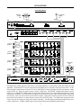
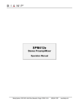
This diagram shows a VSX41 used as an audio router in a "office paging" application. A similar system could be used for factory or school
®
applications. An ADVANTAGE 301 receives input signals from the paging sources, and sends a single output to the VSX41. The 301
may be assigned so signal present in Channels 1 & 2 causes 15dB ducking of Channel 3 (example: mic priority over telephone). (When
®
using the VSX41 as a "router", the Output connector is used as a single input.) PRECEDENCE CMA60s provide power for the four
®
paging zones. An ADVANTAGE DA28R receives input signal from a background music source, and distributes that signal to the Channel
2 input on the four CMA60s. The VSX41 provides four outputs, which are sent to the Channel 1 input on the four CMA60s. (When using
the VSX41 as a "router", the Input connectors are used as the four outputs.) Paging signal is routed to a specific zone via the VSX41 front
panel Channel Select switches or by remote switches connected to the VSX41 Logic Inputs. The CMA60s allow signal present at the
Channel 1 input to cause "page-over" muting of the Channel 2 input signal. This allows paging (and muting of background music) to be
routed to a specific zone. In addition, CMA60 muting (and announcement chimes) may be triggered by remote switches.
9
SPECIFICATIONS
Maximum Input/Output Voltage:
20Vrms
Maximum Input/Output Current:
100mA rms
Remote Translator:
maximum input voltage
+15VDC
minimum input voltage
-15VDC
switching threshold
+2VDC
input voltage when idle (high input)
high ( > +2VDC)
input voltage when idle (low input)
low ( < +2VDC)
Crosstalk (20Hz ~ 20kHz):
-70dB
Power Requirements:
120/240VAC 50/60Hz
Power Consumption:
8 watts max.
Dimensions:
height (1 rack space)
1.75 inches (44mm)
width
19 inches (483mm)
depth
4 inches (102mm)
Weight:
4.5 lbs. (2.04kg)
10
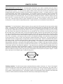
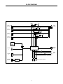
BLOCK DIAGRAM
Advantage VSX41 Block Diagram
relay 1
3.9kΩ
75Ω
input 1
output
(RCA & BNC)
(RCA & BNC)
relay 2
3.9kΩ
75Ω
input 2
(RCA & BNC)
relay 3
3.9kΩ
75Ω
input 3
(RCA & BNC)
relay 4
3.9kΩ
75Ω
input 4
(RCA & BNC)
internal
infrared
receiver
1
2
3
4
remote
2
remote
translator
remote
output
microprocessor
remote
1
signal
translator
1 2 3 4 channel select switches
11
logic
inputs
WARRANTY
BIAMP SYSTEMS IS PLEASED TO EXTEND THE FOLLOWING 5-YEAR
LIMITED WARRANTY TO THE ORIGINAL PURCHASER OF THE
PROFESSIONAL SOUND EQUIPMENT DESCRIBED IN THIS MANUAL.
BIAMP Systems expressly warrants this product to be
free from defects in material and workmanship for a
period of 5 YEARS from the date of purchase as a
new product from an authorized BIAMP Systems
dealer under the following conditions.
1. In the event the warranted BIAMP Systems product
requires service during the warranty period, BIAMP
Systems will repair or replace, at its option, defective
materials, provided you have identified yourself as the
original purchaser of the product to any authorized
BIAMP Systems Service Center. Transportation and
insurance charges to and from an authorized Service
Center or the BIAMP Systems factory for warranted
products or components thereof to obtain repairs shall
be the responsibility of the purchaser.
2. This warranty will be VOIDED if the serial number
has been removed or defaced; or if the product has
been subjected to accidental damage, abuse, rental
usage, alterations, or attempted repair by any person
not authorized by BIAMP Systems to make repairs; or
if the product has been installed contrary to BIAMP
Systems’s recommendations.
3. Electro-mechanical fans, electrolytic capacitors,
and the normal wear and tear of appearance items
such as paint, knobs, handles, and covers are not
covered under this warranty.
4. BIAMP SYSTEMS SHALL NOT IN ANY EVENT BE
LIABLE
FOR
SPECIAL,
INCIDENTAL,
OR
CONSEQUENTIAL DAMAGES, INCLUDING LOST
PROFITS, LOSS OF USE, PROPERTY DAMAGE, INJURY
TO GOODWILL, OR OTHER ECONOMIC LOSS OF ANY
SORT. EXCEPT AS EXPRESSLY PROVIDED HEREIN,
BIAMP SYSTEMS DISCLAIMS ALL OTHER LIABILITY TO
PURCHASER OR ANY OTHER PERSONS ARISING OUT
OF USE OR PERFORMANCE OF THE PRODUCT,
INCLUDING LIABILITY FOR NEGLIGENCE OR STRICT
LIABILITY IN TORT.
5. THIS WARRANTY IS IN LIEU OF ALL OTHER
WARRANTIES EXPRESSED OR IMPLIED.
BIAMP
SYSTEMS EXPRESSLY DISCLAIMS ALL IMPLIED
WARRANTIES OF MERCHANTABILITY AND FITNESS
FOR A PARTICULAR PURPOSE. THE REMEDIES SET
FORTH HEREIN SHALL BE THE PURCHASER’S SOLE
AND EXCLUSIVE REMEDIES WITH RESPECT TO ANY
DEFECTIVE PRODUCT. THE AGENTS, EMPLOYEES,
DISTRIBUTORS, AND DEALERS OF BIAMP SYSTEMS
ARE NOT AUTHORIZED TO MODIFY THIS WARRANTY
OR TO MAKE ADDITIONAL WARRANTIES BINDING ON
BIAMP SYSTEMS.
ACCORDINGLY, ADDITIONAL
STATEMENTS SUCH AS DEALER ADVERTISEMENTS
OR REPRESENTATIONS DO NOT CONSTITUTE
WARRANTIES BY BIAMP SYSTEMS.
6. No action for breach of this warranty may be
commenced more than one year after the expiration of this
warranty.
Thank you for purchasing BIAMP SYSTEMS...
AMERICAN SOUND CRAFTSMANSHIP
Biamp Systems
10074 S.W. Arctic Drive
Beaverton, Oregon 97005
(503) 641-7287
http://www.biamp.com
585.0119.00