1
TM-T85/T85P
Using this online operator’s guide
The words on the left side of this screen are bookmarks for all the
topics in this guide.
Use the scroll bar next to the bookmarks to find any topic you
want. Click a bookmark to instantly jump to its topic. (If you wish,
you can increase the size of the bookmark area by dragging the
dividing bar to the right.)
Use the zoom tools to magnify or reduce the page display.
Click the Find button if you want to search for a particular term.
(However, using the bookmarks is usually quicker.)
Complete online documentation for Acrobat Reader is located in the Help directory for Acrobat Reader.
thermal line printer
TM-T85/T85P
Operator’s Manual
400471502
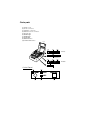
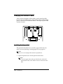
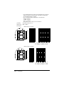
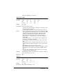
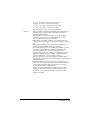
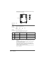
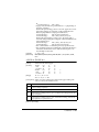
Printer parts
(1) Printer cover
(2) Power connector
(3) Interface connector
(4) Drawer kick-out connector
(5) DIP switches
(6) POWER light
(7) ERROR light
(8) PAPER light
(9) POWER button
(10) PAPER FEED button
(1)
(2)
(3)
(4)
TM-T85
(5)
DIP Switch 1
(2)
DIP Switch 2
(3)
(4)
TM-T85P
(5)
DIP Switch 1
Control Panel
(7)
(6)
(9)
(8)
(10)
All rights reserved. No part of this publication may be reproduced, stored in a
retrieval system, or transmitted in any form or by any means, mechanical,
photocopying, recording, or otherwise, without the prior written permission of Seiko
Epson Corporation. No patent liability is assumed with respect to the use of the
information contained herein. While every precaution has been taken in the
preparation of this book, Seiko Epson Corporation assumes no responsibility for
errors or omissions. Neither is any liability assumed for damages resulting from the
use of the information contained herein.
Neither Seiko Epson Corporation nor its affiliates shall be liable to the purchaser of
this product or third parties for damages, losses, costs, or expenses incurred by
purchaser or third parties as a result of: accident, misuse, or abuse of this product or
unauthorized modifications, repairs, or alterations to this product, or (excluding the
U.S.) failure to strictly comply with Seiko Epson Corporation’s operating and
maintenance instructions.
Seiko Epson Corporation shall not be liable against any damages or problems arising
from the use of any options or any consumable products other than those designated
as Original Epson Products or Epson Approved Products by Seiko Epson
Corporation.
EPSON is a registered trademark of Seiko Epson Corporation.
ESC/POS is a trademark of Seiko Epson Corporation.
NOTICE: The contents of this manual are subject to change without notice.
Copyright © 1995 by Seiko Epson Corporation, Nagano, Japan.
i
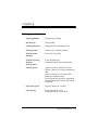
EMC and Safety Standards Applied
Product Name: TM-T85/TM-T85P
Model Name: M65TA / M116A
The following standards are applied only to the printers that are so labeled.(EMC is
tested using the EPSON power supply.)
Europe:
CE marking
Safety: EN60950
North America:
EMI: FCC/ICES-003 Class A
Safety standards: UL 1950
CSA C22.2 No. 950
Japan:
Oceania:
EMI: VCCI Class A
EMC: AS/NZS 3548
WARNING
The connection of a non-shielded printer interface cable to this printer will invalidate
the EMC standards of this device.
You are cautioned that changes or modifications not expressly approved by SEIKO
EPSON could void your authority to operate the equipment.
CE Marking
The printer conforms to the following Directives and Norms
Directive 89/336/EEC
EN 55022 Class B
EN 50082-1
IEC 801-2
IEC 801-3
IEC 801-4
Directive 90/384/EEC
EN45501
ii
FCC Compliance Statement
For American Users
This equipment has been tested and found to comply with the limits for a Class A
digital device, pursuant to Part 15 of the FCC Rules. These limits are designed to
provide reasonable protection against harmful interference when the equipment is
operated in a commercial environment.
This equipment generates, uses, and can radiate radio frequency energy and, if not
installed and used in accordance with the instruction manual, may cause harmful
interference to radio communications. Operation of this equipment in a residential
area is likely to cause harmful interference, in which case the user will be required to
correct the interference at his own expense.
FOR CANADIAN USERS
This Class A digital apparatus complies with Canadian ICES-003.
Cet appareil numérique de la classe A est conforme à la norme NMB-003 du Canada.
GEREÄUSCHPEGEL
Gemäß der Dritten Verordnung zum Gerätesicherheitsgesetz
(Maschinenlärminformations- Verordnung-3. GSGV) ist der arbeitsplatzbezogene
Geräusch-Emissionswert kleiner als 70 dB(A) (basierend auf ISO 7779).
iii
iv
Introduction
The TM-T85 and TM-T85P are one-station printers for issuing coupons, ECR and
POS use which can be used for printing the results of weighing or measuring.
The main features of the TM-T85 and TM-T85P printers are the following:
❏ Light weight and ultra-compact size
❏ High-speed printing: 12 lines per second
❏ Low noise thermal printing
❏ High reliability due to few moving parts
❏ Easy maintenance
❏ Easy paper insertion due to semi-auto loading
❏ Command protocol based on ESC/POS, a widely used standard
❏ Various layouts possible using page mode
❏ Font selecting (12 × 24 or 9 × 24) possible using a command
❏ Characters which can be extended up to 64 times as large as the standard size
selecting possible and smoothing also possible
❏ Four different print densities selecting possible by changing DIP switch settings
❏ Four-way routing of the interface cable, drawer control cable, and power cable:
on either side, underneath, or out the back of the case
❏ Power switch on the front of the printer for easy access; access to sides and back
not necessary
❏ No water entering in the printer by touching the panel switches with a wet hand
❏ Bar code printing both in the vertical direction (fence bar code) and in the
horizontal direction (ladder bar code (✻1)) possible using a bar code command
❏ Repeated operation and copy printing possible through a macro definition
❏ Drawer control possible using the drawer kick out interface
(✻1) Effective only in page mode
v
❏ Bidirectional parallel interface in accordance with the IEEE 1284 Nibble/Byte
Modes
Please be sure to read the instructions in this manual carefully before using your new
EPSON printer.
vi
About This Manual
Setting Up and Using
❏ Chapter 1 contains information on unpacking the printer, setting it up, setting
the DIP switches, and adjusting the paper near end detector.
❏ Chapter 2 contains information on using the printer.
❏ Chapter 3 contains troubleshooting information.
Reference
❏ Chapter 4 contains specifications and character code tables.
Notes, Cautions, and Warnings
Note:
Notes have important information and useful tips on the operation of your
printer.
CAUTION:
Cautions must be observed to avoid minor injury to yourself or
damage to your equipment.
WARNING:
Warnings must be followed carefully to avoid serious bodily
injury.
vii
Contents
Chapter 1 Installation
Unpacking . . . . . . . . . . . . . . . . . . . . . . . . . . . . . . . . . . . . . . . . . . . . . . . . . . . . . . . . . . . . 1-1
Removing the Transportation Spacer . . . . . . . . . . . . . . . . . . . . . . . . . . . . . . . . . . . . . 1-2
Connecting the Printer to the Computer . . . . . . . . . . . . . . . . . . . . . . . . . . . . . . . . . . 1-4
Connecting the Printer to the Drawer . . . . . . . . . . . . . . . . . . . . . . . . . . . . . . . . . . . . . 1-6
Grounding the Printer . . . . . . . . . . . . . . . . . . . . . . . . . . . . . . . . . . . . . . . . . . . . . . . . . . 1-8
Connecting the Power Supply . . . . . . . . . . . . . . . . . . . . . . . . . . . . . . . . . . . . . . . . . . . 1-9
Arranging the Interface Cable . . . . . . . . . . . . . . . . . . . . . . . . . . . . . . . . . . . . . . . . . . . 1-10
Installing the Paper Roll . . . . . . . . . . . . . . . . . . . . . . . . . . . . . . . . . . . . . . . . . . . . . . . . 1-10
Running the Self Test . . . . . . . . . . . . . . . . . . . . . . . . . . . . . . . . . . . . . . . . . . . . . . . . . . . 1-13
Setting the DIP Switches . . . . . . . . . . . . . . . . . . . . . . . . . . . . . . . . . . . . . . . . . . . . . . . . 1-14
Adjusting the Paper Near End Detector . . . . . . . . . . . . . . . . . . . . . . . . . . . . . . . . . . . 1-19
Affixing the Fastening Tape (Optional) . . . . . . . . . . . . . . . . . . . . . . . . . . . . . . . . . . . . 1-21
Chapter 2 Using the Printer
Buttons . . . . . . . . . . . . . . . . . . . . . . . . . . . . . . . . . . . . . . . . . . . . . . . . . . . . . . . . . . . . . . . 2-1
Indicator Lights . . . . . . . . . . . . . . . . . . . . . . . . . . . . . . . . . . . . . . . . . . . . . . . . . . . . . . . . 2-1
Replacing the Roll Paper . . . . . . . . . . . . . . . . . . . . . . . . . . . . . . . . . . . . . . . . . . . . . . . . 2-2
Chapter 3 Troubleshooting
Power problems . . . . . . . . . . . . . . . . . . . . . . . . . . . . . . . . . . . . . . . . . . . . . . . . . . . . . . . 3-1
Printing problems . . . . . . . . . . . . . . . . . . . . . . . . . . . . . . . . . . . . . . . . . . . . . . . . . . . . . . 3-1
Paper handling problems . . . . . . . . . . . . . . . . . . . . . . . . . . . . . . . . . . . . . . . . . . . . . . . 3-3
Hexadecimal Dump . . . . . . . . . . . . . . . . . . . . . . . . . . . . . . . . . . . . . . . . . . . . . . . . . . . . 3-7
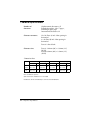
Chapter 4 Reference Information
Printing Specifications . . . . . . . . . . . . . . . . . . . . . . . . . . . . . . . . . . . . . . . . . . . . . . . . . . 4-1
Character Specifications . . . . . . . . . . . . . . . . . . . . . . . . . . . . . . . . . . . . . . . . . . . . . . . . 4-2
Paper Specifications . . . . . . . . . . . . . . . . . . . . . . . . . . . . . . . . . . . . . . . . . . . . . . . . . . . . 4-3
Electrical Specifications . . . . . . . . . . . . . . . . . . . . . . . . . . . . . . . . . . . . . . . . . . . . . . . . . 4-3
Safety and EMI Standards Applied . . . . . . . . . . . . . . . . . . . . . . . . . . . . . . . . . . . . . . . 4-3
Environmental Conditions . . . . . . . . . . . . . . . . . . . . . . . . . . . . . . . . . . . . . . . . . . . . . . 4-4
Interface Specifications . . . . . . . . . . . . . . . . . . . . . . . . . . . . . . . . . . . . . . . . . . . . . . . . . . 4-4
Character code tables . . . . . . . . . . . . . . . . . . . . . . . . . . . . . . . . . . . . . . . . . . . . . . . . . . . 4-5
Chapter 5 Commands
Command Notation . . . . . . . . . . . . . . . . . . . . . . . . . . . . . . . . . . . . . . . . . . . . . . . . . . . . 5-1
Control Commands . . . . . . . . . . . . . . . . . . . . . . . . . . . . . . . . . . . . . . . . . . . . . . . . . . . . 5-2
viii
Chapter 1
Installation
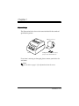
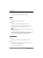
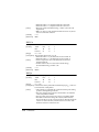
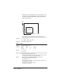
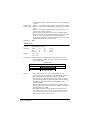
Unpacking
The illustration below shows the items included for the standard
specification printer.
Paper roll (1 pc)
Printer
Hexagonal lock screws (2 pcs)
(only for the serial interface)
If any item is missing or damaged, please contact your dealer for
assistance.
Note:
See the Note on page 1-4 for information about the screws.
Installation 1-1
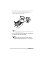
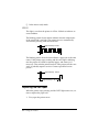
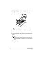
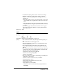
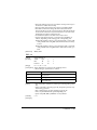
Removing the Transportation Spacer
The printer is protected during shipping by a spacer that must be
removed before you turn on the printer.
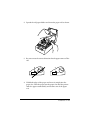
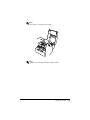
1. First, open the printer cover; next, push the auto cutter holder
back and open the auto cutter; then open the head open lever,
as shown by the arrows below.
Printer cover
Head open lever
Auto cutter
Auto cutter holder
Transportation spacer
1-2 Installation
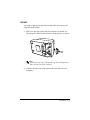
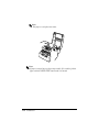
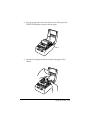
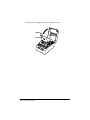
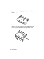
2. Next, remove the orange transportation spacer as shown by the
black arrow in the illustration below. Then place the
transportation spacer in the storage space provided on the
printer as shown by the white arrow.
Note:
Put the transportation spacer back in its original position if you
ever ship or store your printer.
3. Close the head open lever and the auto cutter. When you close
the auto cutter, press firmly until it clicks.
Note:
To prevent paper jams, make sure that the auto cutter tab is
underneath the auto cutter holder as shown on the auto cutter
label.
Installation 1-3
Connecting the Printer to the Computer
You need an appropriate serial interface cable to connect your
computer to the printer.
TM-T85
1. Make sure that the printer and the computer are turned off.
Then plug the cable into the connector on the printer, as shown.
Note:
Your printer comes with inch-type hexagonal lock screws installed.
If you plan to use an interface cable that requires millimeter-type
lock screws, replace the inch-type screws with the enclosed
millimeter-type screws by using a hex screwdriver (5 mm). To
distinguish the two types of screws, see the illustration below.
Notch (one or more lines)
Inch-type
Millimeter-type
2. Connect the other end of the cable to the connector on your
computer.
1-4 Installation
TM-T85P
You need an appropriate parallel interface cable to connect your
computer to the printer.
1. Make sure that the printer and the computer are turned off.
Then plug the cable into the connector on the printer, as shown.
Note:
Squeeze the wire clips on the printer together until they lock in
place on both sides of the connector.
2. Connect the other end of the cable to the connector on your
computer.
Installation 1-5
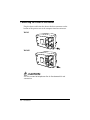
Connecting the Printer to the Drawer
Plug the drawer cable into the drawer kick-out connector on the
bottom of the printer next to the computer interface connector.
TM-T85
TM-T85P
CAUTION:
Do not connect a telephone line to the drawer kick out
connector.
1-6 Installation
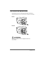
Den Drucker an die Lade anschließen
Das Kabel der Lade an die Schnappsteckerbuchse (neben der
Schnittstellenbuchse) an der Uinterseite des Druckers anschließen.
TM-T85
TM-T85P
ACHTUNG:
Kein Telefonkabel an die Schnappsteckerbuchse
anschließen.
Installation 1-7
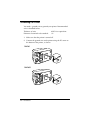
Grounding the Printer
You need a ground wire to ground your printer. Recommended
wire is described below.
Thickness of wire:
Diameter of terminal to be attached:
AWG 18 or equivalent
3.2
1. Make sure that the printer is turned off.
2. Connect the ground wire to the printer using the FG screw on
the bottom of the printer, as shown.
TM-T85
TM-T85P
1-8 Installation
Connecting the Power Supply
This printer requires an external power supply. The Epson Power
Supply PS-150 is recommended.
CAUTION:
Using an incorrect power supply can cause serious damage
to the printer.
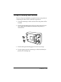
1. Make sure that the power supply is turned off.
2. Plug the power supply’s cable into the printer’s connector as
shown below. Note that the flat side of the connector faces
down.
TM-T85
TM-T85P
3. Plug the power supply’s cord into an outlet.
Installation 1-9
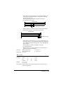
Arranging the Interface Cable
After you have plugged in all the cables, put the interface cable
between the feet on the bottom of the printer and the cable-holding
posts, as shown in the illustration below. This helps keep the cable
securely fastened.
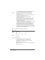
Installing the Paper Roll
The procedure describes how to install a paper roll for the first
time. If you are replacing a used-up paper roll, see page 2-2.
Note:
Be sure to use roll paper that meets the specifications.
1. Open the printer cover. Do not open the auto cutter.
Note:
To prevent paper jams, make sure that the auto cutter tab is
underneath the auto cutter holder as shown on the auto cutter
label.
1-10 Installation
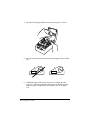
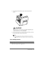
2. Spread the roll paper holder and insert the paper roll as shown.
3. Be sure to note the correct direction that the paper comes off the
roll.
4. Hold both edges of the paper and insert it straight into the
paper slot. Push the paper into the paper slot until the printer
feeds the paper automatically and it comes out of the paper
exit.
Installation 1-11
Note:
The paper is cut by the auto cutter.
Note:
If paper is inserted incorrectly, it may wrinkle. If it wrinkles, feed the
paper with the PAPER FEED button until it is smooth.
1-12 Installation
5. Remove the cut paper and close the printer cover.
Running the Self Test
Any time that you want to check the performance of your printer
you can run the self test described below. This shows whether your
printer is working correctly. It is independent of any other
equipment or software.
1. To perform the self test, close the printer cover if it is open and
hold down the PAPER FEED button while you turn on the
printer with the POWER button.
2. The printer prints the current printer settings and then the
following message:
Self-test printing.
Please press the PAPER FEED button.
Installation 1-13
3. Press the PAPER FEED button to start the second part of the test,
in which the printer prints a pattern using the built-in character
set. It also performs several partial cuts and prints the
following:
*** completed ***
4. Then it performs a full cut and enters the normal mode.
Part of a sample self test is shown below:
TM-T85
TM-T85P
Setting the DIP Switches
You can change the print density or any of your interface settings
by changing the DIP switch settings.
1. Make sure that the printer is off.
1-14 Installation
2. Turn the printer over and remove the DIP switch access cover,
as shown below.
TM-T85
DSW 2
DSW 1
TM-T85P
DSW 1
3. Notice that ON is marked on the switches. Use tweezers or
another narrow tool to move the switches.
Installation 1-15
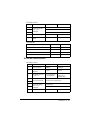
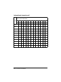
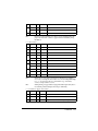
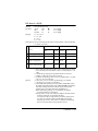
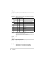
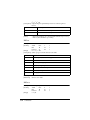
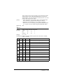
4. Use the following tables to set the DIP switches. Numbers
starting with 1 are in the first set, and numbers starting with 2
are in the second (only for TM-T85).
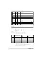
TM-T85 DIP-Switch Functions
DIP Switch Set 1
Switch
Function
ON
OFF
1-1
Data reception error
Ignored
Prints”?”
1-2
Receive buffer capacity
45 bytes
4K bytes
1-3
Handshaking
XON/XOFF
DTR/DSR
1-4
Word length
7 bits
8 bits
1-5
Parity check
Yes
No
1-6
Parity selection
Even
Odd
1-7
See Transmission Speeds table below
1-8
Transmission Speeds
Speed in Bits per Second
SW 1-7
SW 1-8
2400
ON
ON
4800
OFF
ON
9600
ON
OFF
19200
OFF
OFF
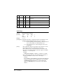
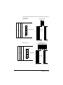
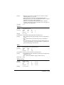
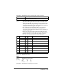
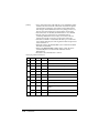
DIP Switch Set 2
Switch
Function
ON
OFF
2-1
Handshaking (BUSY
condition)
Receive buffer full
Off line or receive
buffer full
Selects print density
See Print Density Table below
2-2
2-3
1-16 Installation
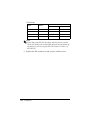
DIP Switch Set 2
Switch
2-4
Function
ON
OFF
Normally OFF
Reserved. Setting
must not be
changed
Normally OFF
2-7
I/F pin 6 reset signal
Enabled
Disabled
2-8
I/F pin 25 reset
signal
Enabled
Disabled
2-5
2-6
Normally OFF
Print Density
Print Density
2-2
2-3
1 (Light)
ON
ON
2
OFF
OFF
3
ON
OFF
4 (Dark)
OFF
ON
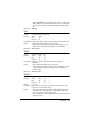
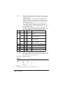
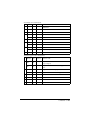
TM-T85P DIP-Switch Functions
DIP Switch Set 1
Switch
Function
ON
OFF
1-1
Auto-line feed
Enabled
Disabled
1-2
Receive buffer
capacity
45 byte
4K bytes
1-3
Handshaking (BUSY
condition)
Receive buffer full
or reading data
Off line, receive
buffer full, or
reading data
Select print density
See Print Density Table below
Normally OFF
1-7
Reserved. Setting
must not be
changed
1-8
Undefined
1-4
1-5
1-6
Normally OFF
Installation 1-17
Print Density
Switch
Switch
Function
4
5
ON
ON
2
OFF
OFF
3
ON
OFF
OFF
ON
1
4
Light
Dark
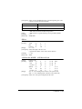
Note:
If you change any DIP switch settings while the printer is turned
on, the new settings will not take effect until you turn the printer off
and back on or reset it (except for the DIP switches 2-7 and 2-8 of
the TM-T85).
5. Replace the DIP switch cover and secure it with the screw.
1-18 Installation
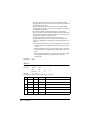
Adjusting the Paper Near End Detector
The paper near end detector detects when the paper is almost gone
by measuring the diameter of the paper roll. Software programs
can use the ESC c 4 command to stop printing when the paper is
almost gone.
If you want to change the amount of paper remaining when the
printer stops printing, follow the steps below to adjust the paper
near end detector.
Note:
The printer also has a paper end-detector that stops the printer at the
very end of a roll. This detector cannot be turned off by software.
1. Open the printer cover and remove the paper roll.
2. Locate the adjusting screw and the positioning plate shown in
the illustration below.
Positioning plate
Adjusting screw
3. Loosen the adjusting screw with a coin or a screwdriver.
Installation 1-19
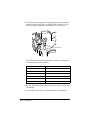
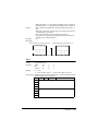
4. Move the positioning plate to the appropriate position and then
tighten the adjusting screw, as shown below. Position 1 leaves
the least paper on the roll, and position 6 leaves the most.
Detecting lever
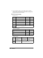
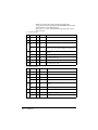
The table below shows the approximate amount of adjustment
of the diameter for each position.
Adjustment Position Number
Adjustment amount
1
Approx. 0 mm (0 in)
2
Approx. 2 mm (0.08 in)
3
Approx. 4 mm (0.16 in)
4
Approx. 6 mm (0.24 in)
5
Approx. 8 mm (0.32 in)
6
Approx. 10 mm (0.39 in)
5. Be sure that the detecting lever moves freely after you finish the
adjustment.
6. Re-install the paper roll, as described earlier in this chapter.
1-20 Installation
Affixing the Fastening Tape (Optional)
Two sets of tape are included as an option to fasten your printer to
a countertop or other surface. Follow the steps below:
1. Clean the countertop or other surface where the printer will be
installed.
2. Peel the green backing paper off of one side of each of the two
sets of tape and affix them to the bottom of the printer, as
shown below.
3. Peel the other green backing paper off of the sets of tape.
4. Press the printer onto the countertop; it will be held firmly in
place by the fastening tape.
Installation 1-21
Chapter 2
Using the Printer
The control panel has two buttons and three lights.
Buttons
POWER
This button turns the printer on and off.
PAPER FEED
This button can be disabled by the ESC c 5 command.
Press this button once to advance the paper one line. Press and
hold this button down to feed the paper continuously.
Note:
You also use this button to execute a macro and to print the second
part of the self test.
The POWER and PAPER FEED buttons also can be used to start the
self test or the hexadecimal dump. The self test is described in
Chapter 1, and the hex dump is described in Chapter 3.
Indicator Lights
POWER
This light is on whenever power is supplied to the printer.
PAPER
This light is on when the paper roll is at the end or near the end.
This light blinks in the following cases:
❏ In the self-test standby mode
Using the Printer 2-1
❏ In the macro ready mode.
ERROR
This light is on when the printer is off line. It blinks to indicate an
error condition.
The blinking pattern shown below indicates that the temperature
of the print head is too high. The printer recovers automatically
and resumes printing when the head cools.
Approximately 160 ms
Approximately 2.56 sec
The blinking pattern shown below indicates a paper jam in the auto
cutter. If the printer stops working and the error light is blinking,
turn the printer off, check for jammed paper, and remove it if
necessary. Then turn the printer back on. If the printer still does not
work, it probably requires service. Contact a qualified service
person.
Approximately 160 ms
Approximately 2.56 sec
Replacing the Roll Paper
When the printer stops printing and the PAPER light comes on, it is
time to replace the paper roll.
1. First, open the printer cover.
2-2 Using the Printer
2. Pull up on the paper and cut it with scissors. Then press the
PAPER FEED button to remove the cut paper.
Cut
3. Spread the roll paper holder and remove the paper roll as
shown.
Using the Printer 2-3
4. Spread the roll paper holder and insert the paper as shown.
5. Be sure to note the correct direction that the paper comes off the
roll.
6. Hold both edges of the paper and insert it straight into the
paper slot. Push the paper into the paper slot until the printer
feeds the paper automatically and it comes out of the paper
exit.
2-4 Using the Printer
Note:
The paper is cut by the auto cutter.
Note:
If paper is inserted incorrectly, it may wrinkle.
Using the Printer 2-5
7. Remove the cut paper and close the printer cover.
2-6 Using the Printer
Chapter 3
Troubleshooting
This chapter gives the solutions to some of the more common
printer problems.
Power problems
The POWER light does not come on.
Make sure that the power supply cables are correctly plugged into
the printer, the power unit, and the power outlet.
Make sure that power is supplied to the power outlet. If the outlet
is controlled by a switch or timer, use another outlet.
Printing problems
The ERROR light is on (not flashing) and nothing is printed.
If the PAPER light is also on, the paper is not loaded or is near the
end of the roll. Install a new roll of paper.
If the PAPER light is not on, probably the printer cover is open.
Close the printer cover.
The ERROR light is flashing and the printer does not print.
There may be a paper jam in the auto cutter. If there is a paper jam,
clear it by following the instructions later in this chapter.
The print head may be too hot. Printing stops and the error light
flashes if the print head is too hot. Printing automatically resumes
when the print head cools.
Troubleshooting 3-1
3. Clean the print head with a cotton swab moistened with
alcohol.
CAUTION:
Be sure that you do not touch the print head with your
fingers because you can damage it.
4. Close the head open lever and the auto cutter. When you close
the auto cutter, press firmly until it clicks.
Note:
To prevent paper jams, make sure that the auto cutter tab is
underneath the auto cutter holder as shown on the auto cutter
label.
Paper handling problems
The paper is jammed inside the printer.
Follow these steps to clear a paper jam:
Troubleshooting 3-3
3. Pull up on the paper roll and cut the paper with scissors so that
is straight as shown below. Remove the jammed paper
carefully in the paper feeding direction.
Cut
CAUTION:
Do not touch the print head. You can damage it.
4. Close the head open lever.
5. Close the auto cutter. When you close it, press firmly until it
clicks.
Note:
To prevent paper jams, make sure that the auto cutter tab is
underneath the auto cutter holder as shown on the auto cutter
label.
6. Re-load the paper.
Troubleshooting 3-5
If you have trouble re-loading the paper, the auto cutter blade may
be in the wrong position. See the illustration below for the correct
position.
If the blade is not in this position, insert a cross-head screwdriver in
the hole on the right side of the auto cutter unit and turn the gear
inside to return the cutter blade to its normal position. See the
illustration below.
3-6 Troubleshooting
The remaining amount of roll paper is not detected correctly.
A microswitch attached to the paper roll near end detector lever
detects when the roll paper is almost gone. You can adjust the
detector lever if necessary. See Chapter 1 for instructions.
Hexadecimal Dump
This feature allows experienced users to see exactly what data is
coming to the printer. This can be useful in finding software
problems. When you turn on the hex dump function, the printer
prints all commands and other data in hexadecimal format along
with a guide section to help you find specific commands.
To use the hex dump feature, follow these steps:
1. Make sure that the printer is off.
2. Open the cover.
3. Hold down the PAPER FEED button while you turn on the
printer by pressing the POWER button.
4. Close the cover. The printer prints “Hexadecimal Dump”.
5. Run any software program that sends data to the printer. All
the codes it receives in a two-column format. The first column
contains the hexadecimal codes and the second column gives
the ASCII characters that correspond to the codes.
sample
Hexadecimal Dump
1B 21 00 1B 26 02 40 40 1B 69 : . ! . . & . @ @.i
1B 25 01 1B 63 34 00 1B 30 31 : . % . c4 . .. 01
41 42 43 44 45 46 47 48 49 4A : ABCDEFGHIJ
Troubleshooting 3-7
❏
A period (.) is printed for each code that has no ASCII
equivalent.
❏ Control codes are printed in bold for emphasis.
❏ During the hex dump all commands except DLE EOT and
DLE ENQ are disabled.
6. Open the cover to set the printer off line so that it will print the
last line.
7. Close the cover and turn off the printer or reset it to turn off the
hex dump mode.
3-8 Troubleshooting
Chapter 4
Reference Information
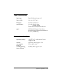
Printing Specifications
Printing Method:
Thermal line printing
Dot Density:
180 x 180 dpi
Printing Direction:
Unidirectional with friction feed
Printing width:
72mm (2.83"), 512 dot positions
Characters/line
(default):
Font A: 42, Font B: 56
Character spacing
(default)
Fonts A and B:
2 dots: 0.28mm(.01")
Programmable by control command
Printing speed:
Approx. 12 lines/second (1/6”feed)
Approx. 50 mm( 2")/second continuous
feed
Approx. 28 mm(1.1")/second when
printing a ladder bar code
Actual speed may be lower, depending
on data transmission speed and control
commands
Paper feed speed:
Approx. 50 mm (2")/second
Line spacing:
Default: 4.23 mm (1/6")
Programmable in 1/360" units
Reference Information 4-1
Character Specifications
Number of
characters
Alphanumeric characters: 95
Extended graphics: 128 x 7 pages,
including 1 space page
International characters: 32
Character structure:
12 x 24 (Font A) incl. 2-dot spacing in
horizontal
9 x 24 (Font B) incl. 2-dot spacing in
horizontal
Font A is the default
Font A: 1.41mm (.06") x 3.39mm (.13")
(WxH)
Font B: 0.99mm (.04") x 3.39mm (.13")
(WxH)
Character size:
Character Sizes
Standard
Double-height
Double width
Dbl Width/Height
W x H (mm)
CPL
W x H (mm)
CPL
W x H (mm)
CPL
W xH (mm)
CPL
Font A
12 x 24
1.41 x 3.39
(.06 x .13”)
42
1.41x 6.77
(.06 x .27”)
42
2.82 x 3.39
(.11 x .13”)
21
2.82 x 6.77
(.11 x .27”)
21
Font B
9 x 24
.99 x 3.39
(.04 x .13”)
56
.99 x 6.77
(.04 x .27”)
56
1.98 x 3.39
(.08 x .13”)
28
1.98 x 6.77
(.08 x .27”)
28
CPL = Characters per line
Space between characters is not included
Characters can be extended up to 64 times the standard size
4-2 Reference Information
Paper Specifications
Paper type:
Specified thermal paper roll
Paper width
+0"
80 +0
–1 mm (3.15” –0.04" )
Roll paper
specifications
Total dia: 83mm max
Core dia: Inside: 12mm
Outside: 18mm
Paper must not be pasted to the core
paper
NTP080-80 (Nakagawa Seisakujo)
[Original paper: Nippon Paper Industries
Co., Ltd., TF50KS-E]
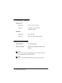
Electrical Specifications
Operating voltage
+24 VDC ± 7% (with optional power
supply PS-150
Current
consumption
(at +24 V,
excluding driving
drawer kickout)
Operating: Mean approx. 1.5A
Peak: approx. 6.0A
Standby: Mean approx. 0.1A
Reference Information 4-3
Environmental Conditions
Temperature
Operating
5 to 40 ° C (41 to 104 ° F)
Storage
–10 to 50 ° C (14 to 122° F)
except for paper
Humidity
Operating
30 to 85% RH
Storage
30 to 90% RH except for paper
Interface Specifications
Serial interface:
RS-232 compatible
Parallel interface:
IEEE 1284 compatible (Nibble/Byte
Modes)
Note:
The interface is a factory installed option. One of the interfaces
(serial or parallel) is already installed.
Note:
Refer to the EPSON TM-T85/T85P Specification for details.
4-4 Reference Information
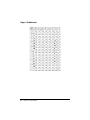
Character Code Tables
Page 0 (PC437: U.S.A., Standard Europe)(International
character set: U.S.A.)
Reference Information 4-5
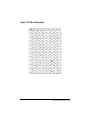
Page 1 (Katakana)
4-6 Reference Information
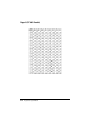
Page 2 (PC850: Multilingual)
Reference Information 4-7
Page 3 (PC860: Portuguese)
4-8 Reference Information
Page 4 (PC863: Canadian-French)
Reference Information 4-9
Page 5 (PC865: Nordic)
4-10 Reference Information
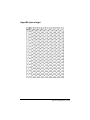
Page 255 (Space Page)
Reference Information 4-11
International character sett
Country
ASCII code (hexadecimal)
Hex
23
24
40
5B
5C
5D
5E
60
7B
7C
7D
7E
Dec
35
36
64
91
92
93
94
96
123
124
125
126
U.S.A.
#
$
@
[
\
]
^
`
{
¦
}
~
France
#
$
à
°
ç
§
^
`
é
ù
è
¨
Germany
#
$
§
Ä
Ö
Ü
^
`
ä
ö
ü
ß
U.K.
£
$
@
[
\
]
^
`
{
¦
}
~
Denmark I
#
$
@
Æ
Ø
Å
^
`
æ
ø
å
~
Sweden
#
¤
É
Ä
Ö
Å
Ü
é
ä
ö
å
ü
Italy
#
$
@
°
\
é
^
ù
à
ò
è
ì
Spain
Pt
$
@
¡
Ñ
¿
^
`
¨
ñ
}
~
Japan
#
$
@
[
¥
]
^
`
{
¦
}
~
Norway
#
¤
É
Æ
Ø
Å
Ü
é
æ
ø
å
ü
Denmark II
#
$
É
Æ
Ø
Å
Ü
é
æ
ø
å
ü
4-12 Reference Information
Chapter 5
Commands
Command Notation
[Name]
[Format]
The name of the command.
The code sequence.
ASCII indicates the ASCII equivalents.
Hex indicates the hexadecimal equivalents.
Decimal indicates the decimal equivalents.
[ ]k indicates the contents of the [ ] should be repeated k times.
[Range]
Gives the allowable ranges for the arguments.
[Description] Describes the function of the command.
[Notes]
Provides important information on setting and using the printer
command, if necessary.
[Default]
Gives the default values, if any, for the command parameters.
[Reference] Lists related commands.
[Example]
Provides examples using the command.
The numbers denoted by < >H are hexadecimal.
The numbers denoted by < >B are binary.
The numbers denoted by < > are decimal.
NOTE:
The phrase "beginning of a line" in command descriptions assumes
that the following conditions have been met:
1. Print data, including spaces and HT command tabs, is not in the
current print buffer.
2. The print position is not specified by the ESC $ or ESC \
command.
Commands 5-1
Control Commands
HT
[Name]
[Format]
Horizontal tab
ASCII
HT
Hex
09
Decimal
9
[Description] Moves the print position to the next horizontal tab position.
[Notes]
• This command is ignored unless the next horizontal tab position
has been set.
• If the next horizontal tab position exceeds the printing area, the
printer sets the printing position to [Printing area width + 1].
• Horizontal tab positions are set with ESC D.
• If this command is received when the printing position is at
[printing area width + 1], the printer executes print buffer-full
printing of the current line and horizontal tab processing from the
beginning of the next line.
[Reference] ESC D
LF
[Name]
[Format]
Print and line feed
ASCII
LF
Hex
0A
Decimal
10
[Description] Prints the data in the print buffer and feeds one line based on the
current line spacing.
[Note]
This command sets the print position to the beginning of the line.
[Reference] ESC 2, ESC 3
FF
[Name]
[Format]
Print and return to standard mode (in page mode)
ASCII
FF
Hex
0C
Decimal
12
[Description] Prints the data in the print buffer collectively and returns to standard
mode.
[Notes]
• The buffer data is deleted after being printed.
• The printing area set by ESC W is reset to the default setting.
• The printer does not execute paper cutting.
• This command sets the print position to the beginning of the line.
• This command is enabled only in page mode.
ESC FF, ESC L, ESC S
[Reference]
5-2 Commands
CR
[Name]
[Format]
Print and carriage return
ASCII
CR
Hex
0D
Decimal
13
[Description] When auto-line feed is enabled, this command functions in the same
way as LF. When auto-line feed is disabled, this command is ignored.
[Notes]
• This command sets the print position to the beginning of the line.
• This command is available only with a parallel interface and is
ignored with a serial interface.
DLE EOT n
[Name]
[Format]
Real-time status transmission
ASCII
DLE
EOT
n
Hex
10
04
n
Decimal
16
4
n
[Range]
1≤ n ≤ 4
[Description] Transmits the selected printer status specified by n in real time,
according to the following parameters:
n = 1: Transmit printer status
n = 2: Transmit off-line status
n = 3: Transmit error status
n = 4: Transmit paper roll sensor status
[Notes]
• The printer transmits the current status. Each status is represented
by one-byte data.
• The printer transmits the status without confirming whether the
host computer can receive data.
• This command is executed even when the printer is in the off-line,
receive buffer is full, or error staus.
• The printer executes this command upon receiving it.
• The status is transmitted whenever the data sequence of
10H(16)04H(4)n (1 ≤ n ≤ 4) is received.
Example:
In ESC ✻ m nL nH [d]K, d1=10H(16), d2=04H(04), d3=01H(1)
• This command should not be used within the data sequence of
another command that consists of 2 or more bytes.
Example:
If you attempt to transmit ESC 3 n to the printer, but DTR (DSR
for the host computer) goes to MARK before n is transmitted
and then DLE EOT 3 interrupts before n is received, the code
10H(16) for DLE EOT 3 is processed as the code for ESC 3
10H(16).
Commands 5-3
• When Auto Status Back (ASB) is enabled using the GS a
command, the status transmitted by the DLE EOT command and
the ASB status must be differentiated.
• If the value of n is out of the specified range, the printer ignores
this command.
n = 1: Printer status
Bit
Off/On
Hex
Decimal
Function
0
Off
00
0
Not used. Fixed to Off.
1
On
02
2
Not used. Fixed to On.
Off
00
0
Drawer open/close signal is LOW (connector pin
3).
On
04
4
Drawer open/close signal is HIGH (connector pin
3).
Off
00
0
On-line.
On
08
8
Off-line.
4
On
10
16
Not used. Fixed to On.
5,6
-
-
-
Undefined.
7
Off
00
0
Not used. Fixed to Off.
2
3
n = 2: Off-line status
Bit
Off/On
Hex
Decimal
Function
0
Off
00
0
Not used. Fixed to Off.
1
On
02
2
Not used. Fixed to On.
Off
00
0
Cover is closed.
On
04
4
Cover is open.
Off
00
0
Paper is not being fed by using the PAPER FEED
button.
On
08
8
Paper is being fed by the PAPER FEED button.
On
10
16
Not used. Fixed to On.
Off
00
0
No paper-end stop.
On
20
32
Printing stops due to paper end.
2
3
4
5
5-4 Commands
Bit
Off/On
Hex
Decimal
Function
Off
00
0
No error.
On
40
64
Error occurs.
Off
00
0
Not used. Fixed to Off.
6
7
Bit 5:
Becomes on when printing stops due to paper-end detected by the
paper roll end sensor or due to a paper near-end enabled by using
the ESC c 4.
n = 3: Error status
Bit
Off/On
Hex
Decimal
Function
0
Off
00
0
Not used. Fixed to Off.
1
On
02
2
Not used.Fixed to On.
2
-
-
-
Undefined.
Off
00
0
No auto-cutter error.
On
08
8
Auto-cutter error occurs.
On
10
16
Not used. Fixed to On.
Off
00
0
No unrecoverable error.
On
20
32
Unrecoverable error occurs.
Off
00
0
No auto-recoverable error.
On
40
64
Auto recoverable error occurs.
Off
00
0
Not used. Fixed to Off.
3
4
5
6
7
Bit 3:
If these errors occur due to paper jams or the like, it is possible to
recover by correcting the cause of the error and executing DLE ENQ
n (1 ≤ n ≤ 2). If an error due to a circuit failure (e.g. wire break)
occurs, it is impossible to recover.
Bit 6:
When printing is stopped due to high print head temperature, bit 6 is
On until the print head temperature drops sufficiently.
n = 4: Continuous paper sensor status
Bit
Off/On
Hex
Decimal
Function
0
Off
00
0
Not used. Fixed to Off.
1
On
02
2
Not used. Fixed to On.
2
Off
00
0
Paper roll near-end sensor. Paper adequate.
Commands 5-5
Bit
Off/On
Hex
Decimal
Function
3
On
0C
12
Paper near-end is detected by the paper roll nearend sensor.
4
On
10
16
Not used. Fixed to On.
5
Off
00
0
Paper roll end sensor. Paper present.
6
On
60
96
Paper end is detected by the paper roll end sensor.
7
Off
00
0
Not used. Fixed to Off.
[Reference]
DLE ENQ, ESC u, ESC v, GS a, GS r
DLE ENQ n
[Name]
[Format]
Real-time request to printer
ASCII
DLE
ENQ
n
Hex
10
05
n
Decimal
16
5
n
[Range]
1≤n≤2
[Description] The printer responds to a request from the host specified by n. The
operations performed depend on the value of n, as follows:
n = 1: Restarts printing from the beginning of the line where an
error occurred, after recovering from the error.
n = 2: Recovers from an error after clearing the receive and
print buffers.
[Notes]
• The command is effective only when an auto-cutter error occurs.
• The printer executes this command upon receiving it.
• This command is also executed when the receive buffer is full.
• The status is transmitted whenever the data sequence of 10H(16)
05H(5)n (1 ≤ n ≤ 2) is received.
Example:
In ESC ✻m nL nH [d] K, d1=10H(16) , d2=05H(5) , d3=01H(1)
• This command should not be used within the data sequence of
another command that consists of two or more bytes.
Example:
If you attempt to transmit ESC 3 n to the printer, but DTR (DSR
for the host computer) goes to MARK before n is transmitted,
and DLE ENQ 2 interrupts before n is received, the code
10H(16) for DLE ENQ 2 is processed as the code for ESC 3
10H(16).
5-6 Commands
[Reference]
• Even if DLE ENQ 2 is executed, the printer retains the settings (by
ESC !, ESC 3, etc.) that were in effect when the error occurred. The
printer can be initialized completely by using DLE ENQ and ESC
@.
DLE EOT
CAN
[Name]
[Format]
Cancel print data in page mode
ASCII
CAN
Hex
18
Decimal
24
[Description] In page mode, deletes all the print data in the current printable area.
[Notes]
• This command is enabled only in page mode.
• If data that existed in the previously specified printing area also
exists in the currently specified printing area, it is deleted.
[Reference] ESC L ESC W
ESC FF
[Name]
[Format]
Print data in page mode
ASCII
ESC
FF
Hex
1B
0C
Decimal
27
12
[Description] In page mode, prints all buffered data in the printing area
collectively.
[Notes]
• This command is enabled only in page mode.
• After printing, the printer does not clear the buffered data, setting
values for ESC T and ESC W, and the position for buffering
character data.
[Reference] FF, ESC L, ESC S
ESC SP n
[Name]
[Format]
Set right-side character spacing
ASCII
ESC
SP
n
Hex
1B
20
n
Decimal
27
32
n
[Range]
0 ≤ n ≤ 255
[Description] Sets the character spacing for the right side of the character to [nx
horizontal or vertical motion units].
[Notes]
• The right-side character spacing for double-width mode is twice
the normal value. When characters are enlarged, the right-side
character spacing is n times normal value.
• This command sets values independently in each mode (standard
and page modes).
Commands 5-7
[Default]
[Reference]
• The horizontal and vertical motion unit are specified by GS P.
Changing the horizontal or vertical motion unit does not affect the
current right-side spacing.
• The horizontal and vertical motion unit are specified by GS P.
Changing the horizontal or vertical motion unit does not affect the
current right-side spacing.
• The GS P command can chahge the horizotal (and vertical)
motion unit. However, the value cannot be less than the minimum
horizontal movement amount, and it must be in even units of the
minimum horizontal movement amount.
• In standard mode, the horizontal motion unit is used.
• In page mode, the horizontal or vertical motion unit differs in
page mode, depending on starting position of the printable area as
follows:
1 When the starting position is set to the upper left or lower right
of the printable area using ESC T, the horizontal motion unit (x)
is used.
2 When the starting position is set to the upper right or lower left
of the printable area using ESC T, the vertical motion unit (y) is
used.
• The maximum right-side spacing is 255/180 inches. Any setting
exceeding the maximum is converted to the maximum
automatically.
n=0
GS P
ESC ! n
[Name]
[Format]
Select print mode(s)
ASCII
ESC
!
n
Hex
1B
21
n
Decimal
27
33
n
[Range]
0 ≤ n ≤ 255
[Description] Selects print mode(s) using n as follows:
Bit
Off/On
Hex
Decimal
Function
Off
00
0
Character font A( 12 ✕ 24) selected.
On
01
1
Character font B (9 ✕ 24) selected.
1
-
-
-
Undefined.
2
-
-
-
Undefined
Off
00
0
Emphasized mode not selected.
On
08
8
Emphasized mode selected.
0
3
5-8 Commands
Bit
Off/On
Hex
Decimal
Function
Off
00
0
Double-height mode not selected.
On
10
16
Double-height mode selected.
Off
00
0
Double-width mode not selected.
On
20
32
Double-width mode selected.
-
-
-
Undefined.
Off
00
0
Underline mode not selected.
On
80
128
Underline mode selected.
4
5
6
7
[Notes]
[Default]
[Reference]
• Determine the values of n by adding the values of all the
characteristics you want to select.
• When both double-height and double-width modes are selected,
quadruple size characters are printed.
• The printer can underline all characters, but can not underline the
space set by HT, ESC $, or ESC \ or 90° clockwise rotated
characters.
• The thickness of the underline is that selected by ESC -, regadless
of the character size.
• When some characters in a line are double or more height, all the
characters on the line are aligned at the baseline.
• ESC E can also tutn on or off emphasized mode. However, the
setting of the last received command is effective.
• ESC - can also turn on or off underline mode. However , the
setting of the last received command is effective.
• GS ! can also select character size. However, the setting of the last
received command is effective.
n=0
ESC –, ESC E, GS !
ESC $ nL nH
[Name]
[Format]
Set absolute print position
ASCII
ESC
$
nL nH
Hex
1B
24
nL nH
Decimal
27
36
nL nH
[Range]
0 ≤ nL ≤ 255
0 ≤ nH ≤ 255
[Description] Sets the distance from the beginning of the line to the position at
which subsequent characters are to be printed.
Commands 5-9
[Notes]
[Reference]
5-10 Commands
• The distance from the beginning of the line to the print position is
[(nL + nH ✕ 256) ✕ (vertical or horizontal motion unit)] inches.
• Settings outside the specified printable area are ignored.
• The horizontal and vertical motion unit are specified by GS P.
• The GS P command can change the horizontal (and vertical)
motion unit. However, the value cannot be less than the minimum
horizontal movement amount, and it must be in even units of the
minimum horizontal movement amount.
• In standard mode, the horizontal motion unit (x) is used.
• In page mode, horizontal or vertical motion unit differs
depending on the starting position of the printable area as follows:
1 When the starting position is set to the upper left or lower right
of the printable area using ESC T, the horizontal motion unit (x)
is used.
2 When the starting position is set to the upper right or lower left
of the printable area using ESC T, the vertical motion unit (y) is
used.
ESC \, GS $, GS \, GS P
ESC % n
[Name]
[Format]
Select/cancel user-defined character set
ASCII
ESC
%
n
Hex
1B
25
n
Decimal
27
37
n
[Range]
0 ≤ n ≤ 255
[Description] Selects or cancels the user-defined character set.
• When the Least Significant Bit (LSB) is 0, the user-defined
character set is canceled.
• When the LSB is 1, the user-defined character set is selected.
[Notes]
• When the user-defined character set is canceled, the internal
character set is automatically selected.
[Default]
n=0
[Reference] ESC &, ESC ?
ESC & y c1 c2 [x1 d1...dy ✕ x1]...[xk d1...dy ✕ xk]
[Name]
[Format]
Define user-defined characters
ASCII
ESC
&
y c1 c2 [x1 d1...dy ✕ x1]...[xk d1...dy ✕ xk]
Hex
1B
26
y c1 c2 [x1 d1...dy ✕ x1]...[xk d1...dy ✕ xk]
Decimal
27
38
y c1 c2 [x1 d1...dy ✕ x1]...[xk d1...dy ✕ xk]
[Range]
y=3
32 ≤ c1 ≤ c2 ≤ 126
0 ≤ x ≤ 12 Font A (12 ✕ 24)
0 ≤ x ≤ 9 Font B (9 ✕ 24 )
0 ≤ d1 ... dy ✕ xk ≤ 255
k=c2-c1+1
[Description] Defines user-defined characters.
• y specifies the number of bytes in the vertical direction.
• c1 specifies the beginning character code for the definition, and c2
specifies the final code.
• x specifies the number of dots in the horizontal direction.
• d is the dot data for the characters. The dot pattern is in the
horizontal direction from the left side. Any remaining dots on the
right side are blank.
• The allowable character code range is from ASCII code 20H(32) to
7EH(126) (95 characters).
• The data to define a user-defined character is (y x x) bytes.
• Set a corresponding bit to 1 to print a dot or 0 to not print a dot.
[Notes]
• It is possible to define multiple characters for consecutive
character codes.
If only one character is desired, use c1 = c2 .
• This command can define different user-defined character
patterns by each fonts. To select a font, use ESC !
Commands 5-11
[Default]
[Reference]
[Example]
• A user-defined character and a downloaded bit image cannot be
defined simultaneously. When this command is executed, the
downloaded bit image is cleared.
• The user-defined character definition is cleared when:
Esc@ is executed.
GS ✽ is executed.
ESC ? is executed.
The printer is reset or the power is turnde off.
The internal character set
ESC %, ESC ?
• When font A is selected.
12 dots
d1 d4 d7
d
34
MSB
d
35
d2 d5
24
dots
d
36
d3 d6
LSB
d1= <0F>H d4 = <30>H d7 = <40>H....
d2 = <03>H d5 = <80>H d8 = <40>H....
d3 = <00>H d6 = <00>H d9 = <20>H....
• When font B is selected.
9 dots
d1 d4 d7
d2 d5
24
dots
d3 d6
d
25
MSB
d
26
d
27
LSB
d1 = <03>H d4 = <01>H d7 = <02>H....
d2 = <FF>H d5 = <00>H d8 = <00>H....
d3 = <FF>H d6 = <20>H d9 = <10>H....
5-12 Commands
ESC ✽ m nL n H [d]k
[Name]
[Format]
Select bit-image mode
✽
ASCII
ESC
m nL nH [d]k
Hex
1B
2A
m nL nH [d]k
Decimal
27
42
m nL nH [d]k
[Range]
m = 0, 1, 32, 33
0 ≤ nL ≤ 255
0 ≤ nH ≤ 3
0 ≤ d ≤ 255
[Description] Selects a bit-image mode using m for the number of dots specified by
nL and nH, as follows:
Vertical Direction
Horizontal Direction (*1)
m
Mode
Number of
Dots
Dot
Density
Dot
Density
Number of Data
(K)
0
8-dot single-density
8
60 DPI
90 DPI
nL + nH ✕ 256
1
8-dot double-density
8
60 DPI
180 DPI
nL + nH ✕ 256
32
24-dot single-density
24
180 DPI
90 DPI
(nL + nH ✕ 256
)✕ 3
33
24-dot double-density
24
180 DPI
180 DPI
(nL + nH ✕ 256
)✕ 3
[Notes]
• The nL and nH indicate the number of dots of the bit image in the
horizontal direction. The number of dots is calculated by nL + nH
✕ 256.
• If the bit-image data input exceeds the number of dots to be
printed on a line, the excess data is ignored.
• d indicates the bit-image data. Set a corresponding bit to 1 to print
a dot or to 0 to not print a dot.
• If the values of m is out of the specified range, nL and data
following are processed as normal data.
• If the width of the printing area set by GS L and GS W less than
the width required by the data sent with the ESC ✽ command, the
following will be performed on the line in question (but the
printing cannot exceed the maximum printable area):
➀ The width of the printing area is extended to the right to
accommodate the amount of data.
➁ If step ➀ does not provide sufficient width for the data, the left
margin is reduced to accommodate the data.
For each bit of data in single-density mode, the printer prints
two dots: for each bit of data in double-density mode, the
printer prints one dot. This must be considered in calculating
the amount of data that can be printed in one line.
Commands 5-13
• After printing a bit image, the printer returns to normal data
processing mode.
• This command is not affected by print modes (emphasized, doublestrike, and underline, etc.), except upside-down mode.
5-14 Commands
• The relationship between the image data and the dots to be printed
is as follows:
Bit-image data
8-dot bit image
d1 d2 d3
MSB
d1
Bit-image data
d2 d3
Print data
❏ = 1 dot
LSB
Print data
24-dot bit image
Bit-image data
d1 d2d3 d4d5d6 d7d8 d9
MSB
d1
d2 d3
Bit-image data
Print data
❏ = 1 dot
LSB
Single density
Double density
Commands 5-15
ESC - n
[Name]
[Format]
Turn underline mode on/off
ASCII
ESC
n
Hex
1B
2D
n
Decimal
27
45
n
[Range]
0 ≤ n ≤ 2, 48 ≤ n ≤ 50
[Description] Turns underline mode on or off, based on the following values of n.
n
Function
0, 48
Turns off underline mode
1, 49
Turns on underline mode (1-dot thick)
2, 50
Turns on underline mode (2-dots thick)
[Notes]
[Default]
[Reference]
• The printer can underline all characters (including right-side
character spacing), but cannot underline the space set by HT.
• The printer cannot underline 90° clockwise rotated characters and
white/black inverted characters.
• When underline mode id turned off by setting the value of n to 0
or 48, the following data is not underlined, and the underline
thickness set before the mode is turned off does not change. The
default underline thickness is 1 dot.
• Changing the character size does not affect the current underline
thickness.
• Underline mode can also be turned on or off by using ESC !. Note,
however, that the last received command is effective.
n=0
ESC !
ESC 2
[Name]
[Format]
Select 1/6-inch line spacing
ASCII
ESC
2
Hex
1B
32
Decimal
27
50
[Description] Selects 1/6-inch line spacing.
[Note]
The line spacing can be set independently in standard mode and in
page mode.
[Reference] ESC 3
ESC 3 n
[Name]
[Format]
5-16 Commands
Set line spacing
ASCII
ESC
Hex
1B
3
33
n
n
Decimal
27
51
n
[Range]
0 ≤ n ≤ 255
[Description] Sets the line spacing to [n x vertical or horizontal motion unit]
inches.
[Notes]
• The line spacing can be set independently in standard mode and
in page mode.
• The horizontal and vertical motion unit are specified by GS P.
Changing the horizontal or vertical motion unit does not affect the
current line spacing.
• The GS P command can change the horizontal (and vertical)
motion unit. However, the value cannot be less than the minimum
vertical movement amout, and it must be in even units of the
minimum vertical movement amount.
• In standard mode, the vertical motion unit (y) is used.
• In page mode, this command functions as follows, depending on
the starting position of the printable area:
➀ When the starting position is set to the upper left or lower right
of the printable area using ESC T, the vertical motion unit (y) is
used.
➁ When the starting position is set to the upper right or lower left
of the print able area using ESC T, the horizontal motion unit (x)
is used.
• The maximum line spacing is 40 inches. When the setting value
exceeds the maximum, it is converted to the maximum
automatically.
[Default]
n = 60 (1/6 inch)
[Reference] ESC 2, GS P
ESC = n
[Name]
[Format]
Set peripheral device
ASCII
ESC
=
n
Hex
1B
3D
n
Decimal
27
61
n
[Range]
0 ≤ n ≤ 255
[Description] Selects the device to which the host computer sends data, using n as
follows:
• Each bit of n is used as follows:
Bit
Off/On
Hex
Decimal
Function
0
Off
00
0
Printer disabled.
On
01
1
Printer enabled.
-
-
-
Undefined.
1
Commands 5-17
Bit
Off/On
Hex
Decimal
Function
2
-
-
-
Undefined.
3
-
-
-
Undefined.
4
-
-
-
Undefined.
5
-
-
-
Undefined.
6
-
-
-
Undefined.
7
-
-
-
Undefined.
[Notes]
[Default]
[Reference]
• When the printer is disabled, it ignores all data except for errorrecovery commands (DLE ENQ 1, DLE ENQ 2) until it is enabled
by this command.
n=1
DLE ENQ
ESC ? n
[Name]
[Format]
Cancel user-defined characters
ASCII
ESC
?
n
Hex
1B
3F
n
Decimal
27
63
n
[Range]
32 ≤ n ≤ 126
[Description] Cancels user-defined characters.
[Notes]
• This command cancels the pattern defined for the character code
specified by n. After the user-defined characters is canceled, the
corresponding pattern for the internal character is printed.
• This command deletes the pattern defined for the specified code
in the font selected by ESC !
• If a user-defined character has not been defined for the specified
character code, the printer ignores this command.
[Reference] ESC &, ESC %
ESC @
[Name]
[Format]
Initialize printer
ASCII
ESC
@
Hex
1B
40
Decimal
27
64
[Description] Clears the data in the print buffer and resets the printer mode to the
mode that was in effect when the power was turned on.
[Notes]
• The DIP switch settings are not checked again.
• The data in the receive buffer is not cleared.
5-18 Commands
• The macro definition is not cleared.
ESC D [n] k NUL
[Name]
[Format]
Set horizontal tab positions
ASCII
ESC
D
[n] k
NUL
Hex
1B
44
[n] k
00
Decimal
27
68
[n] k
0
[Range]
1 ≤ n ≤ 255
0 ≤ k ≤ 32
[Description] Sets horizontal tab positions.
• n specifies the column number for setting a horizontal tab position
from the beginning of the line.
• k indicates the total number of horizontal tab positions to be set.
[Notes]
• The horizontal tab position is stored as a value of [character width
✕ n] measured from the beginning of the line. The character width
includes the right-side character spacing, and double-width
characters are set with twice the width of normal characters.
• This command cancels the previous horizontal tab settings.
• When setting n = 8, the print position is moved to column 9 by
sending HT.
• Up to 32 tab positions (k = 32) can be set. Data exceeding 32 tab
positions is processed as normal data.
• Transmit [n]k in ascending order and place a NUL code 0 at the
end.
• When [n]k is less than or equal to the preceding value [n]k-1, tab
setting is finished and the following data is processed as normal
data.
• ESC D NUL cancels all horizontal tab positions.
• When [n]k exceeds the number of characters printable on one line,
the tab position set is equal to the maximum printable column
plus 1.
• The previously specified horizontal tab positions do not change,
even if the character width changes.
[Default]
The default tab positions are at intervals of 8 characters (columns 9,
17, 25,...) for the font A (12 × 24).
[Reference] HT
ESC E n
[Name]
[Format]
Turn emphasized mode on/off
ASCII
ESC
E
n
Hex
1B
45
n
Decimal
27
69
n
[Range]
0 ≤ n ≤ 255
[Description] Turns emphasized mode on or off.
Commands 5-19
[Notes]
[Default]
[Reference]
• When the LSB of n is 0, emphasized mode is turned off.
• When the LSB of n is 1, emphasized mode is turned on.
• Bit image and downloaded bit image , and bar code cannot be
emphasized.
• ESC ! also turns on and off emphasized mode. However, the last
received command is effective.
n=0
ESC !
ESC G n
[Name]
[Format]
Turn on/off double-strike mode
ASCII
ESC
G
n
Hex
1B
47
n
Decimal
27
71
n
[Range]
0 ≤ n ≤ 255
[Description] Turns double-strike mode on or off.
• When the LSB of n is 0, double-strike mode is turned off.
• When the LSB of n is 1, double-strike mode is turned on.
[Notes]
• Printer output is the same in double-strike mode and in
emphasized mode.
• Double-strike mode can not be used for the bit image,
downloaded bit image, and bar code.
[Default]
n=0
[Reference] ESC E
ESC J n
[Name]
[Format]
Print and feed paper
ASCII
ESC
J
n
Hex
1B
4A
n
Decimal
27
74
n
[Range]
0 ≤ n ≤ 255
[Description] Prints the data in the print buffer and feeds the paper [n x vertical or
horizontal motion unit] inches.
[Notes]
• After printing is completed, this command sets the print starting
position to the beginning of the line.
• The paper feed amount set by this command does not affect the
values set by ESC 2 or ESC 3.
• The horizontal and vertical motion unit are specified by GS P.
• The GS P command can change the vertical (and horizontal)
motion unit. However, the value cannot be less than the minimum
vertical movement amount, and it must be in even units of the
minimun vertical movement amount.
5-20 Commands
[Reference]
• In standard mode, the printer uses the vertical motion unit (y).
• When this command is used in page mode, the command
functions as follows, depending on the starting position of the
printable area.
➀ When the starting position is set to the upper left or lower right
of the printable area using ESC T, the vertical motion unit (y) is
used.
➁ When the starting position is set to the upper right or lower left
of the printable area using ESC T, the horizontal motion unit (x)
is used.
• The maximum paper feed amount is 40 inches. Even if a paper
feed amount of more than 40 inches is set, the printer feeds the
paper only 40 inches.
GS P
ESC L
[Name]
[Format]
Select page mode
ASCII
ESC
L
Hex
1B
4C
Decimal
27
76
[Description] Switches from standard mode to page mode.
[Notes]
• This command is enabled only when input at the beginning of a
line.
• This command has no affect in page mode.
• After printing by FF is completed or by using ESC S, the printer
returns to standard mode.
• This command sets the position where data is buffered to the
position specified by ESC T within the printing area defined by
ESC W.
• This command switches the settings for the following commands
(in which the values can be set independently in standard mode
and page mode) to those for page mode:
➀ Set right-side character spacing: ESC SP
➁ Select 1/6-inch line spacing: ESC 2
➂ Set line spacing: ESC 3
• Only valve settings is possible for the following commands; these
commands are not executed.
➀ Turn 90° clockwise rotation mode on/off: ESC V
➁ Select justification : ESC a
➂ Turn upside-down printing mode on/off : ESC {
➃ Set left margin: GS L
➄ Set printable area width: GS W
• The printer returns to standard mode by using the ESC @ or
DLE ENQ 2.
Commands 5-21
[Reference]
FF, CAN,ESC, FF, ESC S, ESC T, ESC W, GS $, GS\
ESC R n
[Name]
[Format]
Select an international character set
ASCII
ESC
R
n
Hex
1B
52
n
Decimal
27
82
n
[Range]
0 ≤ n ≤ 10
[Description] Selects an international character set n from the following table:
n
Character set
0
U.S.A.
1
France
2
Germany
3
U.K.
4
Denmark I
5
Sweden
6
Italy
7
Spain
8
Japan
9
Norway
10
Denmark II
[Default]
[Reference]
n=0
Character Code Tables
ESC S
[Name]
[Format]
Select standard mode
ASCII
ESC
S
Hex
1B
53
Decimal
27
83
[Description] Switches from page mode to standard mode.
[Notes]
• This command is effective only in page mode.
• Data buffered in page mode are cleared.
• This command sets the print position to the beginning of the line.
• The printing area set by ESC W are initialized.
5-22 Commands
[Reference]
• This command switches the settings for the following commands
(in which the values can be set independently in standard mode
and page mode) to those for standard mode:
➀ Set right-side character spacing: ESC SP
➁ Select 1/6-inch line spacing: ESC 2
➂ Set line spacing: ESC 3
FF, ESC FF, ESC L
ESC T n
[Name]
[Format]
Select print direction in page mode
ASCII
ESC
T
n
Hex
1B
54
n
Decimal
27
84
n
[Range]
0≤n≤3
48 ≤ n ≤ 51
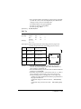
[Description] Selects the print direction and starting position in page mode.
n specifies the print direction and starting position as follows:
Left to right
Upper left
(A in the figure)
1, 49
Bottom to top
Lower left
(B in the figure)
2, 50
Right to left
Lower right
(C in the figure)
3, 51
Top to bottom
Upper right
(D in the figure)
[Notes]
A
Printing area
B
0, 48
C
Starting Position
Paper feed direction
Print Direction
D
n
• When the command is input in standard mode, the printer
executes only internal flag operation. This command does not
affect printing in standard mode.
• This command sets the position where data is buffered within the
printing area set by ESC W.
• Parameters for horizontal or vertical motion units (X or y ) differ as
follows, depending on the starting position of the printing area:
➀ If the starting position is the upper left or lower right of the
printing area, data is buffered in the direction perpendiccular to
the paper feed direction:
Commands using horizontal motion units: ESC SP, ESC $,
ESC \
Commands using vertical motion units: ESC 3, ESC J, GS $,
GS \
Commands 5-23
[Default]
[Reference]
➁ If the starting position is the upper right or lower left of the
printing area, data is buffered in the paper feed direction:
Commands using horizontal motion units: ESC 3, ESC J, GS
$, GS \
Cmmands using vertical motion units: ESC SP, ESC $, ESC \
n=0
ESC $, ESC L, ESC W, ESC \, GS $, GS P, GS \
ESC V n
[Name]
[Format]
Turn 90° clockwise rotation mode on/off
ASCII
ESC
V
n
Hex
1B
56
n
Decimal
27
86
n
[Range]
0 ≤ n ≤ 1, 48 ≤ n ≤ 49
[Description] Turns 90° clockwise rotation mode on or off.
n is used as follows:
n
Function
0, 48
Turns off 90 ° clockwise rotation mode
1, 49
Turns on 90 ° clockwise rotation mode
[Notes]
[Default]
[Reference]
• When underline mode is turned on, the printer does not underline
90° clockwise-rotated characters.
• Double-width and double-height commands in 90° rotation mode
enlarge characters in the opposite directions as from doubleheight and double-width commands in normal mode.
• This command has no effect in page mode.
• If this command is input in page mode, the printer performs only
internal flag operations.
n=0
ESC !, ESC -
ESC W xL xH yL yH dxL dxH dyL dyH
[Name]
[Format]
Set printing area in page mode
ASC II
ESC
W
xL xH yL yH dxL dxH dyL dyH
Hex
1B
57
xL xH yL yH dxL dxH dyL dyH
Decimal
27
87
xL xH yL yH dxL dxH dyL dyH
[Range]
0 ≤ xL, xH, yL, yH, dxL, dxH, dyL, dyH ≤ 255
[Description] • The horizontal starting position, vertical starting position, printing
area width, and printing area height are defined as x0, y0, dx
(inch), dy (inch), respectively.
Each setting for the printing area is calculated as follows:
5-24 Commands
[Notes]
•
•
•
•
•
•
•
•
•
x0 = [(xL + xH ✕ 256) ✕ (horizontal motion unit)]
y0 = [(yL + yH ✕ 256) ✕ (vertical motion unit)]
dx = [dxL + dxH ✕ 256) ✕ (horizontal motion unit)]
dy = [dyL + dyH ✕ 256) ✕ (vertical motion unit)]
The printing area is set as shown in the figure below.
If this command is input in standard mode, the printer executes
only internal flag operation. This command does not affect
printing in standard mode.
If the horizlntal or vertical starting position is set outside the
printable area, the printer stops command processing and
processes the following data as normal data.
If the printing area width or height is set to 0, the printer stops
command processing and processes the following data as normal
data.
This command sets the position where data is buffered to the
position specified by ESC T within the printing area.
If (horizontal starting position + printing area width) exceeds the
printable area, the printing area width is automatically set to
(horizontal printable area - horizontal starting position).
If (vertical starting position + printing area height ) exceeds the
printable area, the printing area height is automatically set to
(vertical printable area - vertical starting position ).
The horizontal and vertical motion unit are specified by GS P.
Changing the horizontal or vertical motion unit does not affect the
current printing area.
The GS P command can change the horizontal (and vertical)
motion unit. However, the value cannot be less than the minimum
horizontal movement amount, and it must be in even units of
minimum horizontal movement amount.
Use the horizontal motion unit (x) for setting the horizontal
starting position and printing area width, and use the vertical
motion unit (y) for setting the vertical starting position and
printing area height.
Commands 5-25
• When the horizontal starting position , vertical starting position,
printing area width, and printing area height are defined as X, Y,
Dx, and Dy respectively, the printing area is set as show in the
figure on the next page.
(0, 0)
Paper feed direction
paper
(x, y)
Dy
Dx
Printing area
(X+DX-1, *Y + Dy=1)
[Default]
[Reference]
• The printable area for this printer is 512/180 inches in the
horizontal direction and 1662/360 inches in the vertical direction.
xL = xH = yL = yH = 0
dxL = 0, dxH = 2, dyL = 126, dyH = 6
CAN, ESC L, ESC T, GS P
ESC \ nL nH
[Name]
[Format]
Set relative print position
ASCII
ESC
\
nL nH
Hex
1B
5C
nL nH
Decimal
27
92
nL nH
[Range]
0 ≤ nL ≤ 255
0 ≤ nH ≤ 255
[Description] Sets the print starting position based on the current position by using
the horizontal or vertical motion unit.
• This command sets the distance from the current position to [(nL +
nH ✕ 256) ✕ horizontal or vertical motion unit]
[Notes]
• Any setting that exceeds the printable area is ignored.
• When pitch N is specified to the right:
nL+ nH ✕ 256 = N
When pitch N is specified to the left (the negative direction), use
the complement of 65536.
When pitch N is specified to the left:
nL+ nH ✕ 256 = 65536 - N
5-26 Commands
[Reference]
• The print starting position moves from the current position to [N ✕
horizontal or vertical motion unit]
• The horizontal and vertical motion unit are specified by GS P.
• The GS P command can change the horizontal (and vertical)
motion unit. However, the value cannot be less than the minimum
horizontal movement amount, and it must be in even units of the
minimum horizontal movement amount.
• In standard mode, the horizontal motion unit is used.
• In page mode, the horizontal or vertical motion unit differs as
follows, depending on the starting point of the printing area:
➀ When the starting position is set to the upper left or lower right
of the printable area using ESC T, the horizontal motion unit (x)
is used.
➁ When the starting position is set to the upper right or lower left
of the printable area using ESC T, the vertical motion unit (y) is
used.
ESC $, GS P
ESC a n
[Name]
[Format]
Select justification
ASCII
ESC
a
n
Hex
1B
61
n
Decimal
27
97
n
[Range]
0 ≤ n ≤ 2, 48 ≤ n ≤ 50
[Description] Aligns all the data in one line to the specified position.
n selects the type of justification as follows:
n
Justification
0, 48
Left justification
1,49
Centering
2, 50
Right justification
[Notes]
[Default]
[Example]
• The command is enabled only when input at the beginning of the
line.
• If this command is input in page mode, the printer performs only
internal flag operation.
• This command does not affect printing in page mode.
• Lines are justifiedwithin the specified printing area.
• Spaces set by HT, ESC $, and ESC \ are all justified.
n=0
Commands 5-27
Left justification
Centering
ABC
Right justification
ABC
ABC
ABCD
ABCD
ABCD
ABCDE
ABCDE
ABCDE
ESC c 3 n
[Name]
[Format]
Select paper sensor(s) to output paper end signals
ASCII
ESC
c
3
n
Hex
1B
63
33
n
Decimal
27
99
51
n
[Range]
0 ≤ n ≤ 255
[Description] selects paper sensor(s) to output paper end signals, using n as
follows:
Bit Off/On
Hex
Decimal
Function
Off
00
0
Paper roll near-end sensor disabled.
On
01
1
Paper roll near-end sensor enabled.
Off
00
0
Paper roll near-end sensor disabled.
On
02
2
Paper roll near-end sensor enabled.
Off
00
0
Paper roll end sensor disabled.
On
04
4
Paper roll sensor enabled.
Off
00
0
Paper roll end sensor disabled.
On
08
8
Paper roll end sensor enabled.
Off
00
0
Undefined.
On
10
16
Undefined.
Off
00
0
Undefined.
On
20
32
Undefined.
Off
00
0
Undefined.
On
40
64
Undefined.
Off
00
0
Undefined.
On
80
128
Undefined.
0
1
2
3
4
5
6
7
5-28 Commands
[Notes]
[Default]
• It is possible to select multiple sensors to output signals. Then, if
any of the sensors detects a paper end, the paper end signal is
output.
• This command is available only with a parallel interface and is
ignored with a serial interface.
• Sensor is switched when executing this command. Because of this,
the paper-out signal switching may delay depending on the
receive buffer state.
n = 15
Commands 5-29
ESC c 4 n
[Name]
[Format]
Select paper sensor(s) to stop printing
ASCII
ESC
c
4
n
Hex
1B
63
34
n
Decimal
27
99
52
n
[Range]
0 ≤ n ≤ 255
[Description] Selects the paper sensor(s) used to stop printing when a paper-end is
detected, using n as follows:
Bit
Off/On
Hex
Decimal
Function
Off
00
0
Paper roll near-end sensor disabled.
On
01
1
Paper roll near-end sensor enabled.
Off
00
0
Paper roll near-end sensor disabled.
On
02
2
Paper roll near-end sensor enabled.
2
-
-
-
Undefined.
3
-
-
-
Undefined.
4
-
-
-
Undefined.
5
-
-
-
Undefined.
6
-
-
-
Undefined.
7
-
-
-
Undefined.
0
1
[Notes]
[Default]
• When a paper end is detected, printing stops after printing the
current line and feeding the paper.
• The printer goes off-line after printing stops.
• The paper roll near-end sensor is enabled when either bit 0 or 1 is
1.
n=0
ESC c 5 n
[Name]
[Format]
Enable/disable panel buttons
ASCII
ESC
c
5
n
Hex
1B
63
35
n
Decimal
27
99
53
n
[Range]
0 ≤ n ≤ 255
[Description] Enables or disables the panel buttons.
• When the LSB of n is 0, the panel buttons are enabled.
• When the LSB of n is 1, the panel buttons are disabled.
5-30 Commands
[Notes]
[Default]
• When the panel buttons are disabled, none of them are usable
when the printer cover is closed.
• In this printer, the panel button is the PAPER FEED button.
• When the printer cover is open, the PAPER FEED button is enabled
regardless of the settings of this command.
• In the macro ready mode, the PAPER FEED button is enabled
regardless of the settings of this command; however, the paper can
not be fed by using this button.
n=0
ESC d n
Print and feed n lines
ASCII
ESC
d
n
Hex
1B
64
n
Decimal
27
100
n
[Range]
0 ≤ n ≤ 255
[Description] Prints the data in the print buffer and feeds n lines.
[Notes]
• This command sets the print starting position to the beginning of
the line.
• This command does not affect the line spacing set by ESC 2 or
ESC 3.
• The maximum paper feed amount is 40 inches. If the paper feed
amount (nx line spacing) of more than 40 inches is specified, the
printer feeds the paper only 40 inches.
[Name]
[Format]
ESC i
[Name]
[Format]
Execute partial cut (one point left uncut)
ASCII
ESC
i
Hex
1B
69
Decimal
27
105
[Description] Executes a partial cut with one point left uncut.
[Notes]
• In standard mode, this command is enabled only when input at the
beginning of a line.
• This command and GS V 1 cut paper in the same way.
[Reference] GS V
ESC p m t1 t2
[Name]
[Format]
[Range]
Generate pulse
ASCII
ESC
Hex
1B
Decimal
27
m = 0, 1, 48, 49
p
70
112
m t1 t2
m t1 t2
m t1 t2
Commands 5-31
0 ≤ t1 ≤ t2 ≤ 255
[Description] Outputs the pulse specified by t1 and t2 to connector pin m as
follows:
m
Connector pin
0, 48
Drawer kick-out connector pin 2
1, 49
Drawer kick-out connector pin 5
[Notes]
• The pulse ON time is [t1 ✕ 2 ms] and the OFF time is [t2 ✕ 2 ms].
• If t2 < t1, the OFF time is [t1 ✕ 2 ms]
ESC t n
[Name]
[Format]
Select character code table
ASCII
ESC
t
n
Hex
1B
74
n
Decimal
27
116
n
[Range]
0 ≤ n ≤ 5, n = 255
[Description] Selects a page n from the character code table.
n
Page
0
0 (PC437 [U.S.A., Standard Europe])
1
1 (Katakana)
2
2 (PC850 [Multilingual])
3
3 (PC860 [Portuguese])
4
4 (PC863 [Canadian-French])
5
5 (PC865 [Nordic])
255
Space page
[Default]
[Reference]
n=0
Character Code Tables
ESC u n
[Name]
[Format]
[Range]
5-32 Commands
Transmit peripheral device status
ASCII
ESC
u
n
Hex
1B
75
n
Decimal
27
117
n
n = 0, 48
[Description] Transmits the status of connector pin n, using n as follows:
n
Connector pin
0, 48
Drawer kick-out connector pin 3
[Notes]
Bit
• When DTR/DSR control is selected, the printer transmits only 1
byte after confirming that the host is ready to receive data (DSR
signal is SPACE). If the host computer is not ready to receive data
(DSR signal is MARK), the printer keeps waiting until the host is
ready. When XON/XOFF control is selected, the printer transmits
only 1 byte without checking the DSR signal.
• This command is executed when the data is processed in the
receive buffer. Therefore, there may be a time lag between
receiving the command and transmitting the status, depending on
the receive buffer status.
• When Auto Status Back (ASB) is enabled using GS a, the status
transmitted by ESC u and the ASB status must be differentiated.
• When the connector is not used, the value of bit 0 is always 1.
• The status to be transmitted is shown in the table below.
Off/On
Hex
Decimal
Function
Off
00
0
Level of pin 3 is Low.
On
01
1
Level of pin 3 is High.
1
-
-
-
Undefined.
2
-
-
-
Undefined.
3
-
-
-
Undefined.
4
Off
00
0
Not used. Fixed to Off.
5
-
-
-
Undefined.
6
-
-
-
Undefined.
7
Off
00
0
Not used. Fixed to Off.
0
[Reference]
DLE EOT, GS a, GS r
ESC v
[Name]
[Format]
Transmit paper sensor status
ASCII
ESC
V
Hex
1B
76
Decimal
27
118
[Description] Transmits the current paper sensor status.
Commands 5-33
[Notes]
• When DTR/DSR control is selected, the printer transmits only 1
byte after confirming that the host is ready to receive data (DSR
signal is SPACE).
If the host computer is not ready to receive data (DSR signal is
MARK), the printer waits until the host is ready. When XON/
XOFF control is selected, the printer transmits only 1 byte without
checking the DSR signal.
• This command is executed when the data is processed in the
receive buffer. Therefore, there may be a time lag between
receiving the command and transmitting the status, depending on
the receive buffer status.
• When Auto Status Back (ASB) is enabled using GS a, the status
transmitted by ESC v and the ASB status must be differentiated.
• The status to be transmitted is shown in the table below:
Bit
Off/On
Hex
Decimal
Function
0
Off
00
0
Paper roll near-end sensor. Paper is
present.
1
On
03
3
Paper roll near-end sensor.
Paper is not present.
2
Off
00
0
Paper roll end sensor.
Paper is present.
3
On
(0C)
(12)
Paper roll end sensor.
Paper is not present.
4
Off
00
0
Not used. Fixed to Off.
5
-
-
-
Undefined.
6
-
-
-
Undefined.
7
Off
00
0
Not used. Fixed to Off.
Bits 2and 3:
[Reference]
When the paper roll end sensor detects a paper end, the printer goes
off-line and does not execute this command. Therefore, bits 2 and 3
do not transmit the status of paper end.
DLE EOT, GS a, GS r
ESC { n
[Name]
[Format]
Turns on/off upside-down printing mode
ASCII
ESC
{
n
Hex
1B
7B
n
Decimal
27
123
n
[Range]
0 ≤ n ≤ 255
[Description] Turns upside-down printing mode on or off.
5-34 Commands
[Notes]
[Default]
[Example]
• When the LSB of n is 0, upside-down printing mode is turned off.
• When the LSB of n is 1, upside-down printing mode is turned on.
• This command is enabled only when input at the beginning of a
line.
• When this command is input in page mode, the printer performs
only internal flag operations.
• This command does not affect printing in page mode.
• In upside-down printing mode, the printer rotates the line to be
printed by 180° and then prints it.
n=0
When upside-down printing mode is off
When upside-down printing mode is on
A B C D E F G
A B C D E F G
0 1 2 3 4 5 6
0 1 2 3 4 5 6
Paper feed direction
GS ! n
[Name]
[Format]
Select character size
ASCII
GS
!
n
Hex
1D
21
n
Decimal
29
33
n
[Range]
0 ≤ n ≤ 255
(1 ≤ vertical number of times ≤ 8,1≤horizontal number of times ≤8)
[Description] Selects the character height using bits 0 to 2 and selects the character
width using bits 4 to 7, as follows:
Bit
Off/On
Hex
Decimal
Function
0
Character height selection. See Table 2.
1
2
3
4
Character width selection. See Table 1.
5
6
7
Commands 5-35
Table 1
Character Width Selection
Table 2
Character Height Selection
Hex
Decimal
Width
Hex
Decimal
Height
00
0
1 (normal)
00
0
1 (normal)
10
16
2 (double-width)
01
1
2 (double-hight)
20
32
3
02
2
3
30
48
4
03
3
4
40
64
5
04
4
5
50
80
6
05
5
6
60
96
7
06
6
7
70
112
8
07
7
8
[Notes]
[Default]
[Reference]
• This command is effective for all characters (except for HRI
characters).
• It n is outside of the defined range, this command is ignored.
• In standard mode, the vertical derection is the paper feed
direction, and the horizontal derection is perpendicular to the
paper feed direction. However, when character orientation
changes in 90° clockwise-rotation mode, the relationship between
vertical and horizontal directions is reversed.
• In page mode, vertical and horizontal directions are based on the
character orientation.
• When characters are enlarged with different sizes on one line, all
the characters on the line are aligned at the baseline.
• The ESC ! command can also turn double-width and doubleheight modes on or off. However, the setting of the last received
command is effective.
n=0
ESC !
G S $ nL nH
[Name]
[Format]
Set absolute vertical print position in page mode
ASCII
GS
$
nL nH
Hex
1D
24
nL nH
Decimal
29
36
nL nH
[Range]
0 ≤ nL, nH ≤ 255
[Description] • Sets the absolute vertical print starting position for buffer
character data in page mode.
• This command sets the absolute print position to [(nL + nH ✕ 256)
✕ (vertical or horizontal motion unit)] inches.
[Notes]
• This command is effective only in page mode.
• If the [(nL + nH ✕ 256) ✕ (vertical or horizontal motion unit)]
exceeds the specified printing area, this command is ignored.
5-36 Commands
‘
[Reference]
• The horizontal starting buffer position does not move.
• The reference starting position is that specified by ESC T.
• This command operates as follows, depending on the starting
position of the printing area specified by ESC T:
➀ When the starting position is set to the upper left or lower right,
this command sets the absolute position in the vertical
direction.
➁ When the starting position is set to the upper right or lower left,
this command sets the absolute position in the horizontal
direction.
• The horizontal and vertical motion unit are specified by GS P.
• The GS P command can change the horizpntal and vertical
motion unit.However, the value cannot be less than the minimum
horizontal movement amount, and it must be in even units of the
minimum horizontal movement amount.
ESC $, ESC T, ESC W, ESC \, GS P, GS \,
GS ✻ x y [d] x✕y✕8
[Name]
[Format]
Define downloaded bit image
✻
ASCII
GS
x y [d] x ✕ y ✕ 8
Hex
1D
2A
x y [d] x ✕ y ✕ 8
Decimal
29
42
x y [d] x ✕ y ✕ 8
[Range]
1 ≤ x ≤ 255
1 ≤ y ≤ 48
x ✕ y ≤ 1536
0 ≤ d ≤ 255
[Description] Defines a downloaded bit image using the dots specified by x and y.
• x indicates the number of dots in the horizontal direction.
• y indicates the number of dots in the verticall direction.
• The number of dots is x ✕ 8 in the horizontal direction and y ✕ 8 in
the vertical direction.
• d indicates bit-image data. Set bit to 1 to print a dot and to 0 to not
print a dot.
[Notes]
• If x ✕ y is outside of the specified range, the printer ignores this
command.
• A user-defined character and a downloaded bit image cannot be
defined simultaneously. When this command is executed, the
user-defined character is cleared.
• After a downloaded bit image is defined, it is available uutil ESC
@ or ESC & is executed; the printer is reset; or the power is turned
off.
Commands 5-37
• The figure below shows the relationship between the bit-image
data and dots to be defined.
x ✕ 8 dots
d1 dy + 1
MSB
dy ✕ 2 + 1
y ✕ 8 dots
LSB
dy
dy ✕ 2
[Reference]
dx ✕ y ✕ 8
GS /
GS / m
[Name]
[Format]
Print downloaded bit image
ASCII
GS
/
m
Hex
1D
2F
m
Decimal
29
47
m
[Range]
0 ≤ m ≤ 3, 48 ≤ m ≤ 51
[Description] Prints a downloaded bit image in mode m.
The modes selectable by m are as follows:
m
Mode
Dot density in vertical
Dot density in horizontal
0, 48
Normal
180 DPI
180 DPI
1, 49
Double-width
180 DPI
90 DPI
2, 50
Double-height
90 DPI
180 DPI
3, 51
Quadruple
90 DPI
90 DPI
[Notes]
5-38 Commands
• This command is ignored if a downloaded bit image has not been
defined.
• In standard mode, this command is effective only when the no
data exists in the print buffer.
• This command is not affected by print modes (emphasized,
double-strike, underline, or character size, white/black reverse
printing), except for upsidedown mode.
• If a downloaded bit image exceeds the printing area, the excess
data is not printed.
[Reference]
• If the width of the printing area set by GS L and GS W less than
the width required by the data sent with the GS / command, the
following will be performed on the line in question (but the
printing cannot exceed the maximum printable area):
➀ The width of the printing area is extended to the right to
accommodate the amount of data.
➁ If ➀ step does not provide sufficient width for the data, the left
margin is reduced to accommodate the data.
For each bit of data in normal mode (m=0, 48) and double heigh
mode (m=2, 50), the printer prints one dot: for each bit of data in
double width mode (m=1, 49) and quadruple mode (m=3, 51), the
printer prints two dots.
GS ✽
GS :
[Name]
[Format]
Start/end macro definition
ASCII
GS
:
Hex
1D
3A
Decimal
29
58
[Description] Starts or ends macro definition.
[Notes]
• Macro definition starts when this command is received during
normal operation. Macro definition ends when this command is
received during macro definition.
• When GS ^ is received during macro definition, the priter ends
macro definition and clears the definition.
• Macro is not defined when the power is turned on.
• The defined contents of the macro are not cleared by ESC @.
Therefore, ESC @ can be included in the contents of the macro
definition.
• If the printer receives GS : again immediately after previously
receiving GS : the printer remains in the macro undefined state.
• The contents of the macro can be defined up to 2048 bytes. If the
macro definition exceed 2048 bytes, excess data is not stored.
• While the macro is defined, normal printing is executed.
[Reference] GS ^
GS B n
[Name]
[Format]
Turn white/black reverse printing mode
ASCII
GS
B
n
Hex
1D
42
n
Decimal
29
66
n
[Range]
0 ≤ n ≤ 255
[Description] Turns on or off white/black reverse printing mode.
• When the LSB of n is 0, white/black reverse mode is turned off.
Commands 5-39
[Notes]
• When the LSB of n is 1, white/black reverse mode is turned on.
• In white/black reverse printing mode, print dots and non-print
dots are reversed. (Characters are printed in white on a black
background.)
• This command is available for built-in characters and user-defined
characters.
• When white/black reverse printing mode is on, it also applied to
character spacing set by ESC SP.
• This command does not affect bit image, downloaded bit image,
bar code, HRI characters, and spacing skipped by HT, ESC $, and
ESC \.
• This command does not affect the space between lines.
• White/black reverse mode has a higher priority than underline
mode. Even if underline mode is on, it is disabled (but not
canceled) when white/black reverse mode is selected.
[Default]
n=0
GS H n
[Name]
[Format]
Select printing position for HRI characters
ASCII
GS
H
n
Hex
1D
48
n
Decimal
29
72
n
[Range]
0 ≤ n ≤ 3, 48 ≤ n ≤ 51
[Description] Selects the printing position of HRI characters when printing a bar
code.
n selects the printing position as follows:
n
Printing position
0, 48
Not printed
1, 49
Above the bar code
2, 50
Below the bar code
3, 51
Both above and below the bar code
[Note]
[Default]
[Reference]
• HRI indicates Human Readable Interpretation.
HRI characters are printed using the font specified by GS f.
n=0
GS f, GS K
GS I n
[Name]
[Format]
5-40 Commands
Transmit printer ID
ASCII
GS
Hex
1D
I
49
n
n
Decimal
29
73
n
1 ≤ n ≤ 3, 49 ≤ n ≤ 51
Transmits the printer ID specified by n as follows:
[Range]
[Function]
n
Printer ID
Specification
ID (hexadecimal)
1, 49
Printer model ID
TM-T85/T85P
08H
2, 50
Type ID
See table below.
3, 51
ROM version ID
Depends on ROM version
n = 2, Type ID
Bit
Off/On
Hex
Decimal
Function
0
Off
00
0
Two-byte character code not supported.
1
On
02
2
Auto-cutter equipped.
2
-
-
-
Undefined.
3
-
-
-
Undefined.
4
Off
00
0
Not used. Fixed to Off.
5
-
-
-
Undefined.
6
-
-
-
Undefined.
7
Off
00
0
Not used. Fixed to Off.
[Notes]
• When DTR/DSR control is selected, the printer transmits only 1
byte after confirming that the host is ready to receive data (DSR
signal is SPACE). If the host computer is not ready to receive data
(DSR signal is MARK), the printer waits until the host is ready.
• When XON/XOFF control is selected, the printer transmits only 1
byte without confirming the condition of the DSR signal.
• The printer ID is transmitted when the data in the receive buffer is
developed. Therefore, there may be a time lag between receiving
this command and transmitting the status, depending on the
receive buffer status.
• The ROM version may be changed.
• When Auto Status Back (ASB) is enabled using GS a, the status
transmitted by GS I and the ASB status must be differentiated.
GS L nL nH
[Name]
[Format]
Set left margin
ASCII
GS
Hex
1D
Decimal
29
L
4C
76
nL nH
nL nH
nL nH
Commands 5-41
0 ≤ nL ≤ 255
0 ≤ nH ≤ 255
[Description] Sets the left margin using nL and nH.
• The left margin is set to [(nL + nH ✕ 256) ✕ horizontal motion
unit)] inches.
[Range]
Printable area
Left margin Printing area width
[Notes]
[Default]
[Reference]
• This command is effective only at the beginning of a line.
• If this command is input in page mode, the printer performs only
internal flag operations.
• This command does not affect printing in page mode.
• If the setting exceeds the printable area,the maximum value of the
printable area is used.
• The horizontal and vertical motion unit are specified by GS P.
Changing the horizontal or vertical motion unit does not affect the
current left margin.
• The GS P command can change the horizontal (and vertical)
motion unit.
However, the value cannot be less than the minimum horizontal
movement amount, and it must be in even units of the minimum
horizontal movement amount.
nL = 0, nH = 0
GS P, GS W
GS P x y
[Name]
[Format]
Set horizontal and vertical motion units
ASCII
GS
P
xy
Hex
1D
50
xy
Decimal
29
80
xy
[Range]
0 ≤ x ≤ 255
0 ≤ y ≤ 255
[Description] Sets the horizontal and vertical motion units to 1/x inch and 1/y
inches, respectively.
When x and y are set to 0, the default setting of each value is used
(x = 180, y = 360).
[Notes]
• The horizontal direction is perpendicular to the paper feed
direction and the vertical direction is the paper feed direction.
• In standard mode, the following commands use x or y, regardless
character rotation (upside-down or 90°clockwise rotation):
ESC SP, ESC $, ESC\, GS L, GS W
➀ Command using x:
5-42 Commands
[Default]
[Reference]
➀
➁ Command using y:
ESC 3, ESC J
• In page mode, the following commands use x or y, depending on
character orientation:
➀ When the print starting position is set to the upper left or lower
right of the printing area using ESC T (data is buffered in the
direction perpendicular to the paper feed direction):
Command using x:
ESC SP, ESC $, ESCW, ESC\
Command using y:
ESC 3, ESC J, ESC W, GS $, GS\
➁ When the print starting position is set to the upper right or
lower left of the printing area usinhg ESC T (data is buffered in the
paper feed direction):
Command using x:
ESC 3, ESC J , ESC W, GS $, GS\
Command using y:
ESC SP, ESC $, ESC W, ESC\
• This command does not affect the previously specified values.
• The calculated result from combining this command with others is
turncated to the minimum value of the mechanical pitch or an
exact multiple of that value.
x = 180, y = 360
ESC SP, ESC $, ESC 3, ESC J, ESC W, ESC \, GS $, GS L, GS W,
GS \
GS V m ➁ GS V m n
[Name]
[Format]
Select cut mode and cut paper
1ASCII
GS
V
m
Hex
1D
56
m
Decimal 29
86
m
2ASCII
GS
V
m
n
Hex
1D
56
m
n
Decimal 29
86
m
n
[Range]
10 ≤ m ≤ 1, 48 ≤ m ≤ 49
265 ≤ m ≤ 66, 0 ≤ n ≤ 255
[Description] Selects a mode for cutting paper and executes paper cutting. The
value of m selects the mode as follows:
m
Print mode
0, 48
Full cut (cutting completely)
1, 49
Partial cut (one point left uncut)
65
Feeds paper for (cutting position + [n ✕ (vertical motion unit)]), and cuts the
paper completely.
66
Feeds paper for (cutting position + [n✕ (vertical motion unit)]), and cuts the
paper partially(one point left uncut).
[Note for ➀ and ➁]
Commands 5-43
• In standard mode, this command is effective only at the beginning
of a line.
[Note for ➀] • When m = 1 or 49, this command operates the same way as ESC i.
[Notes for ➁] • When n= 0, the printer feeds the paper to the cutting position and
cuts it.
• When n ≠ 0, the printer feeds the paper to (cutting position + [n ✕
vertical motion unit]) and cuts it.
• The horizontal and vertical motion unit are specified by GS P.
• The paper feed amount is calculated using the vertical motion unit
(y). However, the value cannot be less than the minimum
horizontal movement amount, and it must be in even units of the
mininmum horizontal movement amount.
[Reference] ESC i
GS W nL nH
[Name]
[Format]
Set printing area width
ASCII
GS
W
nL nH
Hex
1D
57
nL nH
Decimal
29
87
nL nH
[Range]
0 ≤ nL ≤ 255
0 ≤ nH ≤ 255
[Description] Sets the printing area width to the area specified by nL and nH.
• The printing area width is set to [(nL + nH ✕ 256) ✕ horizontal
motion unit] inches.
Printable area
Left margin
[Notes]
Printing area width
•
•
•
•
This command is effective only at the beginning of a line.
In page mode, the printer performs only internal flag operations.
This command does not affect the printing in page mode.
The maximum possible setting for the print range is the same as
the maximum printable area in the horizontal position. Settings
exceeding the maximum setting are rounded down to the
maximum setting.
• The horizontal and vertical motion unit are specified by GS P.
Changing the horizontal or vertical motion unit does not affect the
current printing area width.
• The GS P command can change the horizontal (and vertical)
motion unit. However, the value cannot be less than the minimum
horizontal movement amount, and it must be in even units of the
minimum horizontal movement amount.
5-44 Commands
• If the width set for the printing area is less than the width of one
character, when the character data is developed, the following
processing is performed:
➀ The set printing area width is extended to the right to
accommodate one character.
Printable area
A
Extended to right
Left margin
Printing area width set by nL and nH
➁ If the printing area width cannot be extended sufficiently, the
left margin is reduced to accommodate one character.
Printable area
A
Left margin
[Default]
[Reference]
➁Reduce left margin
➀Extended to right
• When developing the bit image for a downloaded bit image, the
following processes are performed if the width of the printing area
is less than the width required by the data sent with the ESC ✻ or
GS / command:
➀ The printing area width is extended to the right to
accommodate the data.
➁ If the printing area is still insufficient at ➀, the left margin is
reduced to accommodate the data.
Thermal paper mode:
nL = 128, nH = 1
Thermal label mode:
nL = 112, nH = 2
GSL, GS P
GS \ nL nH
[Name]
[Format]
Set relative vertical print position in page mode
ASCII
GS
\
nL nH
Hex
1D
5C
nL nH
Decimal
29
92
nL nH
[Range]
0 ≤ nL ≤ 255
0 ≤ nH ≤ 255
[Description] Sets the relative vertical print starting position from the current
position in page mode.
Commands 5-45
[Notes]
[Reference]
• This command sets the distance from the current position to [(nL
+ nH ✕ 256) ✕ vertical or horizontal motion unit] inches.
• This command is ignored Unless page mode is selected.
• When pitch N is specified to the movement downward:
nL + nH ✕ 256 = N
When pitch N is specified to the movement upward (the negative
direction), use the complement of 65536.
When pitch N is specified to the movement upward:
nL + nH ✕ 256 = 65536 - N
• Any setting that exceeds the specified printing area is ignored.
• The reference position is that at which data development starts.
• This command function as follows, depending on the print
starting position set by ESC T:
1 When the starting position is set to the upper left or lower left of
the printing area, the vertical motion unit (y) is used.
2 When the starting position is set to the upper right or lower left
of the printing area, the horizontal motion unit (x) is used.
• The horizontal and vertical motion unit are specifide by GS P.
• The GS P command can change the horizontal (and vertical)
motion unit. However, the value cannot be less than the minimum
horizontal movement amount, and it must be in even units of the
minimum horizontal movement amount.
ESC $,ESC T, ESC W, ESC \, GS $, GS P
GS ^ r t m
[Name]
[Format]
Execute macro
ASCII
GS
^
rtm
Hex
1D
5E
rtm
Decimal
29
94
rtm
[Range]
0 ≤ r ≤ 255
0 ≤ t ≤ 255
0≤m≤1
[Description] Executes a macro.
• r specifies the number of times to execute the macro.
• t specifies the waiting time for executing the macro.
The waiting time is t ✕ 100 msec for every macro execution.
• m specifies macro executing mode.
• When the LSB m = 0:
The macro executes r times continuously at the interval specified by
t.
• When the LSB of m = 1:
5-46 Commands
[Notes]
[Reference]
After waiting for the period specified by t, the LED indicator blinks
and the printer waits for the PAPER FEED button to be pressed.
After the button is pressed, the printer executes the macro once. The
printer repeats the operation r times.
• If this command is received while a macro is being defined, the
macro definition is aborted and the definition is cleared.
• If the macro is not defined or if r is 0, nothing is executed.
• When the macro is executed by pressing the PAPER FEED button
(m = 1), paper can not be fed by using the PAPER FEED button.
GS :
GS a n
[Name]
[Format]
Enable/Disable Automatic Status Back
ASCII
GS
a
n
Hex
1D
61
n
Decimal
29
97
n
[Range]
0 ≤ n ≤ 255
[Description] Enables or disables ASB and specifies the status items to include,
using n as follows:
Bit
Off/On
Hex
Decimal
Status for ASB
Off
00
0
Drawer kick-out connector pin 3 status disabled.
On
01
1
Drawer kick-out connector pin 3 status enabled.
Off
00
0
Off-line status disabled.
On
02
2
Off-line status enabled.
Off
00
0
Error status disabled.
On
04
4
Error status enabled.
Off
00
0
Paper roll sensor status disabled.
On
08
8
Paper roll sensor status enabled.
4
-
-
-
Undefined.
5
-
-
-
Undefined.
6
-
-
-
Undefined.
7
-
-
-
Undefined.
0
1
2
3
Commands 5-47
[Notes]
• If any of the status items in the table above are enabled, the printer
transmits the status when this command is executed. The printer
automatically transmits the status whenever the enabled status
item changes. The disabled status items may change, in this case,
because each status transmission represents the current status.
• If all status items are disabled, the ASB function is also disabled.
• The following four status bytes are transmitted without
confirming whether the host is ready to receive data. The four
status bytes must be consecutive, except for the XOFF code.
• Since this command is executed sfter the data is processed in the
receive buffer, there may be a time lag between data reception and
status transmission.
• When the printer is disabled by ESC =, this command is disabled
but ASB is not disabled.
• When using DLE EOT, ESC u, ESC v, GS I, or GS r, the status
transmitted by these commands and ASB status must be
differentiated.
• The status to be transmitted are as follows:
First byte (printer information)
Bit
Off/On
Hex
Decimal
Status for ASB
0
Off
00
0
Not used. Fixed to Off.
1
Off
00
0
Not used. Fixed to Off.
Off
00
0
Drawer kick-out connector pin 3 is LOW
On
04
4
Drawer kick-out connector pin 3 is HIGH.
Off
00
0
On-line.
On
08
8
Off-line.
On
10
16
Not used. Fixed to On.
Off
00
0
Cover is closed.
On
20
32
Cover is open.
Off
00
0
Paper is not being fed by the PAPER FEED
button.
On
40
64
Paper is being fed by the PAPER FEED button.
Off
00
0
Not used. Fixed to Off.
2
3
4
5
6
7
5-48 Commands
Second byte (error information)
Bit
Off/On
Hex
Decimal
Status for ASB
0
-
-
-
Undefined.
1
-
-
-
Undefined.
2
-
-
-
Undefined.
Off
00
0
No auto-cutter error.
On
08
8
Auto-cutter error.
Off
00
0
Not used. Fixed to Off.
Off
00
0
No unrecoverable error.
On
20
32
Unrecoverable error.
Off
00
0
No automatically recoverable error.
On
40
64
Automatically recoverable error occurs.
Off
00
0
Not used. Fixed to Off.
3
4
5
6
7
Third byte (paper sensor information)
Bi
t
Off/On
Hex
Decimal
Status for ASB
0
Off
00
0
Paper roll near-end sensor.
Paper adequate
1
On
03
3
Paper roll near-end sensor detects a paper nearend.
2
Off
00
0
Paper roll end sensor. Paper present.
3
On
0C
12
Paper roll end sensor detects a paper end.
4
Off
00
0
Not used. Fixed to Off.
5
-
-
-
Undefined.
6
-
-
-
Undefined.
7
Off
00
0
Not used. Fixed to Off.
Commands 5-49
Forth byte (paper sensor information)
Bit
Off/On
Hex
Decimal
Status for ASB
0
-
-
-
Undefined.
1
-
-
-
Undefined.
2
-
-
-
Undefined.
3
-
-
-
Undefined.
4
Off
00
0
Not used. Fixed to Off.
5
-
-
-
Undefined.
6
-
-
-
Undefined.
7
Off
00
0
Not used. Fixed to Off.
[Default]
[Reference]
n = 0 when DIP SW 2-1 (serial interface) or DIP SW 1-3 (parallel
interface) is off, n = 2 when DIP SW 2-1 (serial interface) or DIP SW 13 (parallel interface) is on.
DLE EOT, ESC u, ESC v, GS r
GS b n
[Name]
[Format]
Turns smoothing mode on/off
ASCII
GS
b
n
Hex
1D
62
n
Decimal
29
98
n
[Range]
0 ≤ n ≤ 255
[Description] Turns smoothing mode on or off.
When LSB of n is 0, smoothing mode is turned off.
When LSB of n is 1, smoothing mode is turned on.
[Notes]
• Smoothing mode is available for built-in, user-defined characters.
• Even if smoothing mode is turned on, smoothing is not performed
when either of character width or character height id the normal
size.
[Default]
n=0
[Reference] ESC !, GS !
GS f n
[Name]
[Format]
[Range]
5-50 Commands
Select font for Human Readable Interpretation (HRI) characters
ASCII
GS
f
n
Hex
1D
66
n
Decimal
29
102
n
0 ≤ n ≤ 1, 48 ≤ n ≤ 49
[Description] Selects a font for the HRI characters used when printing a bar code.
n selects a font from the following table:
n
Font
0, 48
Font A (12 × 24)
1, 49
Font B (9 × 24)
[Note]
[Default]
[Reference]
• HRI indicates Human Readable Interpretation.
• HRI characters are printed at the position specified by GS H.
n=0
GS H, GS K
GS h n
[Name]
[Format]
Select bar code height
ASCII
GS
h
n
Hex
1D
68
n
Decimal
29
104
n
[Range]
0 ≤ n ≤ 255
[Description] Selects the height of the bar code.
n specifies the number of dots in the vertical direction.
[Default]
n = 162
[Reference] GS K
➀
GS k m d1...dk NUL
➁
GS k m n d1...dn
[Name]
[Format]
Print bar code
➀ASCII
GS
k
m
d1...dk NUL
Hex
1D
6B
m
d1...dk 00
Decimal 29
107
m
d1...dk 0
➁ASCII
GS
k
m
n
d1...dn
Hex
1D
6B
m
n
d1...dn
Decimal 29
107
m
n
d1...dn
➀ 0 ≤ m ≤ 6 (k and d depends on the bar code system used)
[Range]
➁ 65 ≤ m ≤ 73 (n and d depends on the bar code system used)
[Description] Selects a bar code system and prints the bar code.
Commands 5-51
m selects a bar code system as follows:
m
Bar Code System
Number of Characters
Remarks
0
UPC-A
11 ≤ k ≤ 12
48 ≤ d ≤ 57
1
UPC-E
11 ≤ k ≤ 12
48 ≤ d ≤ 57
2
JAN13 (EAN)
12 ≤ k ≤ 13
48 ≤ d ≤ 57
3
JAN 8 (EAN)
7 ≤ k ≤ 8
48 ≤ d ≤ 57
4
CODE39
1≤k
48 ≤ d ≤ 57,
65 ≤ d ≤ 90, 32, 36,
37, 43, 45, 46, 47
5
ITF
1 ≤ k (even number)
48 ≤ d ≤ 57
6
CODABAR
1≤k
48 ≤ d ≤ 57, 65 ≤ d ≤
68 , 36, 43, 45, 46, 47, 58
65
UPC-A
11 ≤ n ≤ 12
48 ≤ d ≤ 57
66
UPC-E
11 ≤ n ≤ 12
48 ≤ d ≤ 57
67
JAN13 (EAN)
12 ≤ n ≤ 13
48 ≤ d ≤ 57
68
JAN 8 (EAN)
7 ≤ n ≤ 8
48 ≤ d ≤ 57
69
CODE39
1 ≤ n ≤ 255
48 ≤ d ≤ 57,
65 ≤ d ≤ 90, 32, 36, 37,
43, 45, 46, 47
d1 = dk = 42 ([1)
70
ITF
1 ≤ n ≤ 255 (even number)
48≤ d ≤ 57
71
CODABAR
1 ≤ n ≤ 255
48 ≤ d ≤ 57
65 ≤ d ≤ 68
, 36, 43, 45, 46, 47, 58
72
CODE93
1 ≤ n ≤ 255
0 ≤ d ≤ 127
73
CODE128
2 ≤ n ≤ 255
0 ≤ d ≤ 127
➀
➁
[Description for ➀]
• d indicates the character code to be printed and k indicates the
number of characters to be printed.
[Description for ➁]
• n indicates the number of bar code data, and the printer processes
n bytes from the next character data as bar code data.
• d indicates the character code to be printed.
[Notes for ➀]
• This command ends with a NUL code.
5-52 Commands
• When the bar code system used is UPC-A or UPC-E, the printer
prints the bar code data after receiving 12 bytes bar code data and
processes the following data as normal data.
• When the bar code system used is JAN13, the printer prints the
bar code after receiving 13 bytes bar code data and processes the
following data as normal data.
• When n the bar code system used is JAN8, the printer prints the
bar code after receiving 8 bytes bar code data and processes the
following data as normal data.
• The number of data for ITF bar code must be even numbers. When
an odd number of data is input, the printer ignores the last
received data.
[Notes for ➁]
• If n is outside of the specified range, the printer stops command
processing and processes the following data as normal data.
[Notes in standard mode]
• If d is outside of the specified range, the printer only feeds paper
and processes the following data as normal data.
• If the horizontal size exceeds printing area, the printer only feeds
the paper.
• This command feeds as much paper as is required to print the bar
code, regardless of the line spacing specified by ESC 2 or ESC 3.
• This command is enabled only when no data exists in the print
buffer. When data exists in the print buffer, the printer processes
the data following m as normal data.
• After printing bar code, this command sets the print position to
the beginning of the line.
• This command is not affected by print modes (emphasized,
double-strike, underline, or character size), except for upsidedown mode.
[Notes in page mode]
• This command develops bar code data in the print buffer, but does
not print it. After processing bar code data, this command moves
the print position to the right side dot of the bar code.
• If d is out of the specified range, the printer stops command
processing and processes the following data as normal data. In
this case the data buffer position does not change.
• If bar code width exceeds the printing area, the printer does not
print the bar code but moves the data buffer position to the left
side out of the printing area.
• Refer to Figure 3.12.3 for bar code data buffer position.
[Reference]
GSH, GS f, GS h, GS w
GS r n
[Name]
[Format]
Transmit status
ASCII
GS
r
n
Commands 5-53
Hex
1D
72
n
Decimal
29
114
n
[Range]
1 ≤ n ≤ 2, 49 ≤ n ≤ 50
[Description] Transmits the status specified by n as, follows:
n
Function
1, 49
Transmits paper sensor status (same as ESC v)
2, 50
Transmits drawer kick-out connector status (same as ESC u 0)
[Notes]
• When DTR/DSR control is selected, the printer transmits only 1
byte after confirming the host is ready to receive data (DSR signal
is SPACE). If the host computer is not ready to receive data (DSR
signal is MARK), the printer waits until the host is ready.
When XON/XOFF control is selected, the printer transmits only 1
byte without confirming the condition of the DSR signal.
• This command is executed when the data in the receive buffer is
developed. Therefore, there may be a time lag between receiving
this command and transmitting the status, depending on the
receive buffer status.
• When Auto Status Back (ASB) is enabled using GS a, the status
transmitted by GS r and the ASB status must be differentiated.
• The status types to be transmitted are shown below:
Paper sensor status (n = 1, 49):
Bit
Off/On
Hex
Decimal
Status for ASB
0
Off
00
0
Paper roll near-end sensor.
Paper adequate.
1
On
03
3
Paper near-end is detected by the paper roll
near-end sensor.
2
Off
00
0
Paper end is not detected by the paper roll end
sensor.
3
On
(0C)
(12)
Paper end is detected by the paper roll end
sensor.
4
Off
00
0
Not used. Fixed to Off.
5
Off
-
-
Undefined.
6
Off
-
-
Undefined.
7
Off
00
0
Not used. Fixed to Off.
Bits 2 and 3:
5-54 Commands
When the paper roll end sensor detects a paper end, the printer goes
off-line and does not execute this command. Therefore, bits 2 and 3
do not transmit the status of paper end.
Drawer kick-out connector status (n = 2, 50):
Bi
t
Off/On
Hex
Decimal
Status for ASB
Off
00
0
Drawer kick-out connector pin 3 is LOW.
On
01
1
Drawer kick-out connector pin 3 is HIGH.
1
-
-
-
Undefined
2
-
-
-
Undefined.
3
-
-
-
Undefined.
4
Off
00
0
Not used. Fixed to Off.
5
-
-
-
Undefined.
6
-
-
-
Undefined.
7
Off
00
0
Not used. Fixed to Off.
0
[Reference]
DLE EOT, ESC u, ESC v, GS a
GS w n
[Name]
[Format]
Set bar code width
ASCII
GS
w
n
Hex
1D
77
n
Decimal
29
119
n
[Range]
2≤n≤6
[Description] Set the horizontal size of the bar code.
n specified the bar code width as follows::
n
Module Width (mm) for
Multi-level Bar Code
Binary-level Bsar Code
Thin element width
Thick element width
(mm)
(mm)
2
0.282
0.282
0.706
3
0.423
0.423
1.129
4
0.564
0.564
1.411
5
0.706
0.706
1.834
6
0.847
0.847
2.258
• Multi-level bar codes are as follows:
UPC-A, UPC-E, JAN13, JNA8, CODE93, CODE128
• Binary-level bar codes are as follows:
Commands 5-55
[Default]
[Reference]
5-56 Commands
CODE39, ITF, CODABAR
n=3
GS k