1
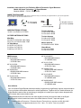
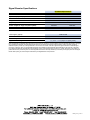
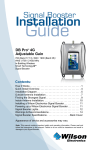
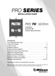
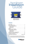
Mobile 3G
Smart Technology
Signal Booster
™
Contents:
How it Works. . . . . . . . . . . . . . . . . . . . . . . . . . . . . . . . . . . 1
Before Getting Started. . . . . . . . . . . . . . . . . . . . . . . . . . . . 2
Quick Installation Overview. . . . . . . . . . . . . . . . . . . . . . . . 2
Installing the Outside Antenna. . . . . . . . . . . . . . . . . . . . . . 2
Installing the Low-Profile Antenna. . . . . . . . . . . . . . . . . . . 3
Installing a Wilson Electronics Signal Booster. . . . . . . . . . 3
Powering Up a Wilson Electronics Signal Booster . . . . . . 3
Understanding the Signal Booster Lights . . . . . . . . . . . . . 4
Warnings and Recommendations. . . . . . . . . . . . . . . . . . . 5
Guarantee and Warranty. . . . . . . . . . . . . . . . . . . . . . . . . . 6
Signal Booster Specifications . . . . . . . . . . . . . . Back Cover
Appearance of device and accessories may vary.
Note: This manual contains important safety and operating information.
Please read and follow the instructions in this manual. Failure to
do so could be hazardous and result in damage to your Signal
Booster.
Installation Instructions for the Following Wilson Electronics Signal Boosters:
Mobile 3G Smart Technology ™ Signal Booster
Model # 460002 FCC ID: PWO460002
INSIDE THIS PACKAGE
Wilson Electronics manufactures a wide variety of antennas to help you customize your Signal Booster for your specific application.
See your dealer or visit www.WilsonElectronics.com.
DC power supply
6V / 2A (859913)
Signal Booster
Slim Low Profile
w/10’ RG174 (301152)
INSIDE ANTENNA OPTIONS
311106 - Low Profile w/ 10’ RG58
Trucker Antenna
311101 w/10.5’ RG58
311701 w/10.5’ RG58
OUTSIDE ANTENNA OPTIONS
Mini-Mag
301126 w/ 12.5 RG174 cable- SMA
301113 w/ 12.5 RG174 cable - FME
12” Mag Mount
311103 w/ 12.5’ RG174
311128 w/ 12.5’ RG174
314202 w/ 12.5’ RG174
NMO Antenna
Kit 311104-5810
• 800/1900 NMO Antenna
• 10’ RG58 Cable
Kit 311112-5810
• 800/1900 NMO Antenna
• 10’ RG58 Cable
Kit 314203-5810
• 800/900/1900 NMO Antenna
• 10’ RG58 Cable
Kit 311104-17410
• 800/1900 NMO Antenna
• 10’ RG174 Cable
12” Mag Mount Antenna
w/ 12.5’ RG174 (311125)
Trucker Antenna
311119 w/13.5’ RG58
311133 w/13.5’ RG58
Marine Antenna
311130-5810 w/10.5’ RG58
Glass Mount
311102 w/14’ RG58
311114 w/14’ RG58
Kit 311104-40015
• 800/1900 NMO Antenna
• 15’ LMR400 Cable
Kit 311112-17410
• 800/1900 NMO Antenna
• 10’ RG174 Cable
Kit 314203-17410
• 800/900/1900 NMO Antenna
• 10’ RG174 Cable
Kit 311112-40015
• 800/1900 NMO Antenna
• 15’ LMR400 cable
Kit 314203-40015
• 800/900/1900 NMO antenna
• 15’ LMR400 cable
How it Works
Your new Wilson Signal Booster has been carefully engineered to significantly improve the performance
of your cell phone and cellular data card in mobile applications. Together with an Outside Antenna, the
Signal Booster’s state-of-the-art technology is designed to increase your signal, reduce dropped calls
and increase data communication rates.
The Outside Antenna will collect the cell tower signal and send it through the cable to the Signal
Booster which is then boosted and sent to the Inside Antenna. Result – improved signal!
1
Contact Wilson Electronics’s Technical Support Team with any questions at 866-294-1660
Or email: [email protected] Mon.- Fri. Hours: 7am to 6 pm MST.
Before Getting Started
This guide will help you properly install your Wilson Electronics Dual-Band Mobile Wireless Signal
Booster. It is important to read through all of the installation steps for your particular application
prior to installing any equipment. Read through the instructions, visualize where all the equipment
will need to be installed and do a soft installation before mounting any equipment. Contact Wilson
Electronics Technical Support Team with any questions at 866-294-1660.
Quick Installation Overview
Installation Diagram
Outside
Antenna
Distance between antennas
through a sunroof must be 5
feet or more.
Cell Phone
PDA
Notebook
!
Warning: In a wireless installation, do not
plug the Signal Booster directly into the cell
phone and/or data card using an antenna
adapter. It may damage the Signal Booster,
cell phone and/or data card.
!
Warning: Do not plug in the DC power
supply until the Outside and Inside
Antenna cables are attached to the Signal
Booster.
Inside
Antenna
DC Power
Supply
Signal
Booster
UH
UH
M
REM
M
REM
Installing the Outside Antenna
Magnet - Mount
Antenna Shown
Part #301103
Carefully
Pull Down
Door Seal
Run Cable
Under Seal
To receive the best cell signal, select a location in the
center of the vehicle’s roof 12 inches away from any other
antennas or windows. If the vehicle has a sunroof, it is
important to separate the Inside and Outside Antennas by
at least five feet. This prevents the Signal Booster from
overloading or oscillating. As shown above. Follow the
specific antenna installation instructions included with the
Outside Antenna.
Separation of the Inside and Outside Antennas is very
important. The metal roof of the vehicle acts as a barrier
and helps shield the two antennas from each other,
preventing oscillation (feedback).
The Outside Antenna must be installed vertically. Signal
performance will be degraded if the antenna is not vertical.
The antenna cable may run through the door to the Signal
Booster.
Tuck Cable
Under Seal
For a more professional looking installation, run the
antenna cable under the door seal. The antenna cable is
small enough to easily tuck under the door seal or plastic
molding. Carefully pull down the door seal. Run the cable
through the seal and push the seal back into place. This
prevents constant wear and tear on the cable as the door
opens and closes.
Contact Wilson Electronics’s Technical Support Team with any questions at 866-294-1660
Or email: [email protected] Mon.- Fri. Hours: 7am to 6 pm MST.
2
Installing the Low-Profile Antenna
Low-Profile
Antenna
Signal Booster
!
Warning: Do not install the Low-Profile Antenna within four
inches of metal (metal found inside the vehicle’s seat will not
affect the antenna’s performance).
!
Warning: Do not plug in the DC power supply until the Outside
and Inside Antenna cables are attached to the Signal Booster.
Installing a Wilson Electronics Signal Booster
Select a location to install the Signal Booster that is away
from excessive heat, direct sunlight, moisture and has proper
ventilation.
Run the cable from the Outside Antenna and attach it to the
connector labeled “Outside Antenna” on the Signal Booster.
Attach the Low-Profile Antenna cable to the connector
labeled “Inside Antenna” on the Signal Booster.
NOTE: The aluminum casing of a Wilson Signal Booster will adjust very quickly to the ambient
temperature of its environment. For example, in the summer, when the inside of a car can reach 140
degrees Fahrenheit, the Signal Booster temperature may be 150 degrees or higher. The casing will
be hot to the touch, similar to a metal door handle or a steering wheel. Such high temperatures will
not damage the Signal Booster, nor do they pose a fire risk to the vehicle. As recommended in these
instructions, install the Signal Booster in a location with adequate ventilation. Keep the area free of items
that could block air flow to the Signal Booster.
Powering up a Wilson Electronics Signal Booster
Connect the power cable from the DC plug-in power supply
to the Signal Booster marked “POWER” and insert the large
end into DC power socket (the vehicle power adapter outlet).
6 V DC / POWER
ON/OFF SWITCH
IMPORTANT:
Do not power up the Signal Booster unless
antenna cables are attached to Signal Booster.
3
The Signal Booster may remain on all the time. However,
leaving the Signal Booster on in a vehicle when it is not
running can discharge or drain the battery in a day or two.
Switch the power supply off when not in use.
A good option is to power the Signal Booster through the
ignition switch so the Signal Booster is turned on and off with
the vehicle.
An available option to do this with is the Hardwire Kit from
Wilson Electronics (#859923).
Contact Wilson Electronics’s Technical Support Team with any questions at 866-294-1660
Or email: [email protected] Mon.- Fri. Hours: 7am to 6 pm MST.
Understanding the Signal Booster Lights
Lights and Troubleshooting for Mobile Boosters
Note: The power light will turn green when the
Signal Booster is successfully powered up. When
the 800 MHz or 1900 MHz lights are lit green, the
Signal Booster is amplifying the outside signal.
All green lights: Signal Booster
is working properly
Green: If the indicator lights on the Signal Booster are
green, the unit is powered up and working properly.
Solid Red Light: Signal Booster
has shut down on that frequency
Red: If one or more lights on the Signal Booster are
red, this indicates that the Signal Booster has shut
down on that frequency to prevent an oscillation
(feedback). First, make sure that all connections are
tight. The Outside Antenna needs to be moved farther
from the Inside Antenna. Move the Outside Antenna
on the roof of the car to the rear of the car, but at least
8-12 inches from the rear or side windows. Reset the
Signal Booster by disconnecting then reconnecting
the power to the Signal Booster.
Blinking Red: If one or more of the lights on the
Signal Booster are blinking red, this means that the
Signal Booster has shutoff due to close proximity to
the handset or mobile device. Increase the distance
between the handset and the Inside Antenna until
the light is no longer flashing red. Contact Wilson
Electronics Technical Support Team for assistance.
Blinking Red: Signal Booster
has shutoff
Contact Wilson Electronics’s Technical Support Team with any questions at 866-294-1660
Or email: [email protected] Mon.- Fri. Hours: 7am to 6 pm MST.
4
Warnings and Recommendations
Warning: In a wireless installation, do not plug the Signal Booster directly into the cell phone or
cellular data card using an antenna adapter. It will damage the Signal Booster, cell
phone or cellular data card.
Warning: Do not plug in the DC power supply until the Outside and Inside Antenna cables are
attached to the Signal Booster.
Warning: The Inside Antennas must have a 1.5 feet of separation distance from all active users.
Warning: RF Safety: Any antenna used with this device must be located at least 8 inches from
all persons.
Warning: Use only the power supply provided in this package. The power supply must be 6 V DC
Output.
This is a CONSUMER device.
BEFORE USE, you MUST REGISTER THIS DEVICE with your wireless provider and have your
provider’s consent. Most wireless providers consent to the use of signal boosters. Some
providers may not consent to the use of this device on their network. If you are unsure, contact
your provider.
You MUST operate this device with approved antennas and cables as specified by the
manufacturer. Antennas MUST be installed at least 20 cm (8 inches) from any person.
You MUST cease operating this device immediately if requested by the FCC or a licensed
wireless service provider.
WARNING. E911 location information may not be provided or may be inaccurate for calls served
by using this device.
This device complies with Part 15 of FCC rules. Operation is subject to two conditions: (1) This device
may not cause harmful interference, and (2) this device must accept any interference received,
including interference that may cause undesired operation. Changes or modifications not expressly
approved by Wilson Electronics could void the authority to operate this equipment.
The Manufacturer’s rated output power of this equipment is for single carrier operation. For situations
when multiple carrier signals are present, the rating would have to be reduced by 3.5 dB, especially
where the output signal is re-radiated and can cause interference to adjacent band users. This power
reduction is to be by means of input power or gain reduction and not by an attenuator at the output of
the device.
5
Contact Wilson Electronics’s Technical Support Team with any questions at 866-294-1660
Or email: [email protected] Mon.- Fri. Hours: 7am to 6 pm MST.
About Wilson Electronics
Wilson Electronics, LLC has been a leader in the wireless communications industry for over 40
years. The company designs and manufactures Signal Boosters, antennas and related components
that significantly improve cellular phone signal reception and transmission in a wide variety of
applications, mobile (vehicle, RV, marine) and in-building (home, office, machine to machine).
With extensive experience in antenna and Signal Booster research and design, the company’s
engineering team uses a state-of-the-art testing laboratory, including an anechoic chamber and
network analyzers, to fine-tune antenna designs and performance. For its Signal Boosters, Wilson
Electronics uses a double electrically shielded RF enclosure and cell tower simulators for compliance
testing.
Wilson Electronics Signal Boosters feature patent-pending Smart Technology ™ that enables them
to automatically adjust their power based on cell tower requirements. By detecting and preventing
oscillation (feedback), signal overload and interference with other users, these Smart Technology ™
Signal Boosters improve network cell phone areas without compromising carrier systems.
All products are engineered and assembled in the company’s 100,000 square-foot headquarters
in St. George, Utah. Wilson Electronics has product dealers in all 50 states as well as in countries
around the world.
30-Day Money-Back Guarantee
All Wilson Electronics products are protected by Wilson Electronics 30-day money-back
guarantee. If for any reason the performance of any product is not acceptable, simply return the
product directly to the reseller with a dated proof of purchase.
2-Year Warranty
Wilson Electronics Signal Boosters are warranted for two (2) years against defects in
workmanship and/or materials. Warranty cases may be resolved by returning the product
directly to the reseller with a dated proof of purchase.
Signal Boosters may also be returned directly to the manufacturer at the consumer’s expense,
with a dated proof of purchase and a Returned Material Authorization (RMA) number supplied
by Wilson Electronics. Wilson Electronics shall, at its option, either repair or replace the product.
Wilson Electronics will pay for delivery of the repaired or replaced product back to the original
consumer within the continental U.S..
This warranty does not apply to any Signal Boosters determined by Wilson Electronics to have
been subjected to misuse, abuse, neglect, or mishandling that alters or damages physical or
electronic properties.
RMA numbers may be obtained by contacting Technical Support at 866-294-1660.
Disclaimer: The information provided by Wilson Electronics, LLC is believed to be complete and
accurate. However, no responsibility is assumed by Wilson Electronics, LLC for any business
or personal losses arising from its use, or for any infringements of patents or other rights of third
parties that may result from its use.
Copyright © 2014 Wilson Electronics, LLC. All rights reserved.
U.S. Patent Nos. – 7,221,967; 7,729,669; 7,486,929; 7,409,186; 7,783,318; 8,583,034; 8,583,033; D565,021
Contact Wilson Electronics’s Technical Support Team with any questions at 866-294-1660
Or email: [email protected] Mon.- Fri. Hours: 7am to 6 pm MST.
6
Signal Booster Specifications
Dual Band Specifications
460002
SMA
50 ohms
6.2 x 3.6 x 1.3 inch or 15.7 x 9.1 x 3.3 cm
1.2 lbs or 0.54 kg
824-894 MHz / 1850-1990 MHz
Model Number
Connectors
Impedance (input/output)
Dimensions
Weight
Frequency
Power output for single cell phone (dBm)
Uplink
Downlink
800 MHz
23.4
-3.1
1900 MHz
23.4
-0.9
Noise Figure (typical)
Isolation
Power Requirements
3 dB nominal
> 90 dB
Signal Booster Usage
6 V, 0.5 A - 1.5 A (subject to uplink power)
Each Signal Booster is individually tested and factory set to ensure FCC compliance. The Signal Booster cannot be adjusted without factory reprogramming or disabling the hardware. The Signal Booster will amplify, but not alter the incoming and outgoing signals in order to increase coverage of
authorized frequency bands only. If the Signal Booster is not in use for five minutes, it will reduce gain until a signal is detected. If a detected signal
is too high in a frequency band, or if the Signal Booster detects and oscillation, the Signal Booster will automatically turn the power off on that band.
For a detected oscillation the Signal Booster will automatically resume normal operation after a minimum of 1 minute. After 5 (five) such restarts, any
problematic bands are permanently shut off until the Signal Booster has been manually restarted by momentarily removing the power from the Signal
Booster. Noise power, gain, and linearity are maintained by the Signal Booster’s microprocessor.
111256_Rev01_01.20.14