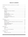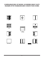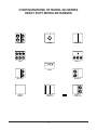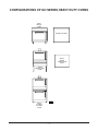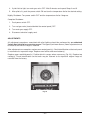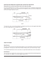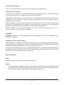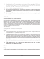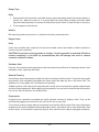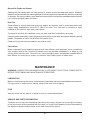
1
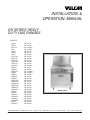
INSTALLATION &
OPERATION MANUAL
GH SERIES HEAVY
DUTY GAS RANGES
MODELS
GH30
GH45
GH3/72
GH6
GH60
GH60T
GH72
GH72/45
GH45/72
GH60/45
GH60T45
GH60/72
GH60T72
GHM30
GHM45
GHM3/72
GHM6
GHM60
GHM60T
GHM72
GHM7245
GHM4572
GHM6045
GHM6T45
GHM6072
GHM6T72
GHX45
GHX60
GHX60T
GHXM45
GHXM60
GHXM60T
GHX72
GHXM72
VULCAN-HART
ML-52141
ML-52142
ML-126406
ML-126402
ML-52144
ML-52171
ML-52145
ML-52176
ML-52180
ML-52174
ML-52186
ML-52175
ML-52188
ML-52151
ML-52152
ML-126408
ML-126404
ML-52154
ML-52172
ML-52155
ML-52179
ML-52181
ML-52177
ML-52187
ML-52178
ML-52189
ML-52217
ML-52218
ML-52223
ML-52220
ML-52221
ML-52224
ML-52219
ML-52222
COMPANY,
FORM 31107 Rev. B (October 2001)
P.O.
MODEL GH30
BOX
696,
LOUISVILLE,
KY
40201-0696,
TEL. (502) 7 7 8 - 2 7 9 1
www.vulcanhart.com
IMPORTANT FOR YOUR SAFETY
THIS MANUAL HAS BEEN PREPARED FOR PERSONNEL QUALIFIED TO INSTALL GAS
EQUIPMENT, WHO SHOULD PERFORM THE INITIAL FIELD START-UP AND
ADJUSTMENTS OF THE EQUIPMENT COVERED BY THIS MANUAL.
POST IN A PROMINENT LOCATION THE INSTRUCTIONS TO BE FOLLOWED IN THE
EVENT THE SMELL OF GAS IS DETECTED. THIS INFORMATION CAN BE OBTAINED
FROM THE LOCAL GAS SUPPLIER.
IMPORTANT
IN THE EVENT A GAS ODOR IS DETECTED, SHUT
DOWN UNITS AT MAIN SHUTOFF VALVE AND
CONTACT THE LOCAL GAS COMPANY OR GAS
SUPPLIER FOR SERVICE.
FOR YOUR SAFETY
DO NOT STORE OR USE GASOLINE OR OTHER
FLAMMABLE VAPORS OR LIQUIDS IN THE
VICINITY OF THIS OR ANY OTHER APPLIANCE.
WARNING
IMPROPER INSTALLATION, ADJUSTMENT,
ALTERATION OR MODIFICATION, SERVICE OR
MAINTENANCE CAN CAUSE PROPERTY
DAMAGE, INJURY OR DEATH. READ THE
INSTALLATION, OPERATING AND MAINTENANCE
INSTRUCTIONS THOROUGHLY BEFORE
INSTALLING OR SERVICING THIS EQUIPMENT.
IN THE EVENT OF A POWER FAILURE, DO NOT
ATTEMPT TO OPERATE THIS DEVICE.
–2–
TABLE OF CONTENTS
CONFIGURATIONS OF MODEL GH SERIES HEAVY DUTY RANGES ......................................... 4
GENERAL ............................................................................................................................................ 8
INSTALLATION .................................................................................................................................... 8
UNPACKING ............................................................................................................................ 8
LOCATION ............................................................................................................................... 8
INSTALLATION CODES AND STANDARDS ......................................................................... 9
ASSEMBLY ............................................................................................................................ 10
LEVELING .............................................................................................................................. 18
GAS CONNECTIONS ............................................................................................................ 18
TESTING THE GAS SUPPLY SYSTEM ............................................................................... 19
FLUE CONNECTIONS .......................................................................................................... 19
ELECTRICAL CONNECTIONS ............................................................................................. 20
LIGHTING AND SHUTTING DOWN PILOTS ....................................................................... 20
ADJUSTMENTS ..................................................................................................................... 22
OPERATION ...................................................................................................................................... 23
BEFORE FIRST USE ............................................................................................................. 23
CONTROLS ............................................................................................................................ 24
INSERTING AND REMOVING STANDARD AND CONVECTION OVEN RACKS ............ 25
USING THE RANGE .............................................................................................................. 25
LOADING AND UNLOADING OVEN .................................................................................... 26
OPERATING SUGGESTIONS .............................................................................................. 26
CLEANING ............................................................................................................................. 27
MAINTENANCE ................................................................................................................................. 30
LUBRICATION ....................................................................................................................... 30
FLUE ....................................................................................................................................... 30
SERVICE AND PARTS INFORMATION .............................................................................. 30
TROUBLESHOOTING ....................................................................................................................... 31
OVEN ...................................................................................................................................... 31
TOP BURNER OPERATION ................................................................................................. 32
–3–
CONFIGURATIONS OF MODEL GH SERIES HEAVY DUTY
RANGES WITH STANDARD AND CONVECTION OVENS
GH45
GH30
GH72
GH6
GH3/72
GH45
FULL BODY
34" WIDE
GH72/45
GH60/GH60T
GH45/72
GH60/72/GH60T72
–4–
PL-53255
GH60/45/GH60T/45
CONFIGURATIONS OF MODEL GH SERIES
HEAVY DUTY MODULAR RANGES
GHM45
GHM30
GHM72
GHM6
GHM3/72
GHM45
GHM72/45
GHM60
GHM60T
GHM45/72
GHM60/72
GHM60T/72
–5–
PL-53256
GHM60/45
GHM60T/45
CONFIGURATIONS OF MODEL GH SERIES HEAVY DUTY
EXPANDO RANGES
MODEL GHX SERIES EXPANDO RANGES WITH CABINET
GHX45
GHX72
GHX60
GHX60T
GHX45 18" WIDE
FULL BODY WITH
CABINET
MODEL
GHXM
SERIES
MODULAR
EXPANDO
RANGES
MODEL
GHXM
SERIES
MODULAR
EXPANDO
RANGES
GHXM45
GHXM60
GHXM60T
GHXM72
PL-51242
GHXM45
–6–
CONFIGURATIONS OF GH SERIES HEAVY DUTY OVENS
GHO1
SINGLE
OVEN
WORK TOP VIEW
GHO1C
SINGLE
CONVECTION
OVEN
GHMO1
ON MODULAR
STAND
PL-51243
GHO2
DOUBLE
STACKED
OVEN
–7–
Installation, Operation and Care Of
MODEL GH SERIES HEAVY DUTY GAS RANGES
PLEASE KEEP THIS MANUAL FOR FUTURE REFERENCE
GENERAL
Vulcan ranges and ovens are produced with quality workmanship and material. Proper installation,
usage and maintenance of your range will result in many years of satisfactory performance.
The manufacturer suggests that you thoroughly read this entire manual and carefully follow all of the
instructions provided.
INSTALLATION
UNPACKING
This range was inspected before leaving the factory. The transportation company assumes full
responsibility for safe delivery upon acceptance of the shipment. Immediately after unpacking, check
for possible shipping damage. If the range is found to be damaged, save the packaging material and
contact the carrier within 15 days of delivery.
Carefully unpack range(s) and place in the approximate installation position, whether as a battery or
single stand-alone range. Remove all shipping wire and wood blocking. Remove parts (packed in a
cardboard box) from oven cavity, or cabinet body, or on top of modular range(s).
Before installing, check the electrical service (Convection Oven Models only) and type of gas supply
(natural or propane) to make sure they agree with the specifications on the rating plate located on the
lower left-hand corner of the front frame behind the bellcrank. If the supply and equipment
requirements do not agree, do not proceed with the installation. Contact your dealer or Vulcan-Hart
Company immediately.
LOCATION
CAUTION: The equipment area must be kept free and clear of combustible substances.
The following ranges, when installed, must have a minimum clearance from combustible construction
of 6" (15 cm) at the sides and 6" (15 cm) at the rear. Clearance from non-combustible construction can
be 0" (0 cm) at the sides and rear:
–8–
GH30
GH45
GH60
GH60T
GH72
GH72/45
GH45/72
GH60/72
GH60T45
GH60/72
GH60T72
GH3/72
GHM30S
GHM60S
GHM60TS
GHM72S
GHM72/45S
GHM45/72S
GHM60/45S
GHM60T45S
GHM60/72S
GHM60T72S
GH6
GHX60
GHX60T
GHXM60S
GHXM60TS
GHX72
GHXM72S
GHX45
Snorkel® Ranges must not be included in back-to-back setups.
The following ranges are to be installed only on non-combustible floors:
GHM72
GHM45
GHM30
GHXM72
GHXM45
GHXM60
GH45/72
GHM45/72
GHM60/72
GHM60/45
GHM3/72
GHM72/45
GHM6
The installation location must allow adequate clearances for servicing and proper operation. A
minimum front clearance of 35" (88 cm) is required.
The range(s) must be installed so that the flow of combustion and ventilation air will not be obstructed.
Adequate clearance for air openings into the combustion chamber(s) must be provided. Make sure
there is an adequate supply of air in the room to allow for combustion of the gas at the burners.
INSTALLATION CODES AND STANDARDS
Your Vulcan range(s) must be installed in accordance with:
In the United States:
1. State and local codes.
2. National Fuel Gas Code, ANSI/Z223.1 (latest edition), available from American Gas Association,
Inc., 1515 Wilson Blvd., Arlington, VA 22209.
3. National Electrical Code ANSI/NFPA-70 (latest edition). Copies available from The National Fire
Protection Association, Batterymarch Park, Quincy, MA 02269.
In Canada:
1. Local codes.
2. CAN/CGA-B149.1 Natural Gas Installation Code (latest edition).
3. CAN/CGA-B149.2 Propane Installation Code (latest edition), available from The Canadian Gas
Association, 178 Rexdale Blvd., Etobicoke, Ontario, Canada M9W 1R3.
4. Canadian Electrical Code, CSA C22.2 No. 3 (latest edition). Copies may be obtained from The
Canadian Standard Association, 178 Rexdale Blvd., Etobicoke, Ontario, Canada M9W 1R3.
–9–
ASSEMBLY
Ranges Mounted on Casters
When ranges are mounted on casters, you must use a connector (available from Vulcan-Hart) that
complies with the Standard for Connectors of Movable Gas Appliances, ANSI-Z21.69 (latest edition),
and a quick-disconnect device that complies with the Standard for Quick-Disconnect Devices
Complying With Gas Fuel, ANSI-Z21.41 (latest edition) or CAN 1-6.9 (latest edition).
Provide a gas line strain relief to limit movement of the range(s) without depending on the connector
and/or any quick-disconnect device or its associated piping to limit movement of the range(s). Attach
the strain relief to the rear of the range (Fig. 1).
CONNECT GAS LINE
STRAIN
RELIEF HERE
PL-51219
Fig. 1
Should it be necessary to disconnect the strain relief, turn off the gas supply before disconnection.
Reconnect the strain relief before turning the gas supply on and returning the range(s) to their
installation position.
Bumper Bars
CAUTION: Failure to install bumper bars may cause motor damage and will void the warranty.
Remove existing #10 screws. Position bumper bars as shown in Fig. 2. Replace #10 screws and secure
bumper bars.
(4) #10 SCREWS
BUMPER BAR
BUMPER BAR
PL-51282
Fig. 2
– 10 –
Battery Installation
If you are installing a new battery range to an existing field appliance manufactured before January,
1998, the union on the existing field appliance must be checked against the union being used on the
new range. The union manufacturer's name around the face surface of the union nut must match. If
the new range has been shipped using a Ward union and the old appliance has something different,
i.e., Stockham, it must be replaced with a Ward union (Fig. 3). Failure to replace this union could result
in a gas leak.
If a Ward union is needed for installation, it must be ordered through the Vulcan-Hart Company Parts
Depot (Part No. FP-088-89).
Fig. 3
Questions or concerns regarding the above installation procedures may be addressed by calling the
Vulcan-Hart Service Department (502) 778-2791.
Proceed with the battery installation as follows:
1. Move next range into position and level as explained in LEVELING. Engage union nut on
manifold pipe with male fitting on next range and draw up union nut hand-tight. Be sure ranges
butt both front and rear. If manifolds do not line up, then ranges are not level. Do not adjust
manifold brackets to make manifolds line up, except in extreme cases, because this will cause
gas valves not to line up perfectly with manifold cover holes. Bolt top frames together, using
10-24 x 1/2" bolts (packed in cloth bag in range oven).
2. Continue leveling, connecting manifold pipe and bolting top frames of ranges together until all
ranges in the battery are connected, then tighten manifold unions gas-tight. Use wrench to keep
section of union assembled to pipe from rotating. Failure to do this may result in misalignment
of valve stems.
3. Unpack high shelves or backguards and remove backsplashes.
4. Place high shelf or backguard in position (see ASSEMBLY- RISER, BACKGUARD AND HIGH
SHELF in this manual).
– 11 –
5. Replace back tops and backsplashes.
6. If front plates do not line up perfectly, adjust by means of bolts under front plate. Similar front
adjustment is provided for the one-piece cast iron griddle (Model GH60) (Fig. 4).
PL-40047-1
Fig. 4
Riser, Backguard and High Shelf
Remove the shipping brackets on the corner of the range where a high shelf support casting is to be
bolted. It is not necessary to remove either shipping bracket on ranges equipped with a backguard as
the brackets will be used for support when remounting the rear top plate and backguard backsplash.
1. Carefully unpack riser, backguard or high shelf with back down, on floor in front of range. Remove
backsplash panel from riser, backguard or high shelf.
2. Remove top castings, back top and shipping brackets from the range. Identify top casting(s) so
they are replaced in the same positions on the same range as when received from the factory.
When assembling a riser, backguard or high shelf to batteried equipment, remove only the extreme
right and left shipping brackets of setup section requiring mounting (Fig. 5).
– 12 –
Fig. 5
3. Carefully lift riser, backguard or high shelf over range (Fig. 6).
4. Carefully guide support channels into the two openings provided at the rear of the range (Fig. 7).
Fig. 7
Fig. 6
– 13 –
While lowering support channels into openings, be sure that the lower angle flange of the riser,
backguard or high shelf is positioned outside the flue back (Fig. 8).
Fig. 8
Once the backguard is setting in place on the range, install the left and right end caps. End caps simply
slide on, in between the splasher and the backguard. There is a tab on the cap that can be pulled out
or pushed in (with a screwdriver) to adjust cap for tightness. Two caps are packaged with each
backguard in a separate plastic bag. Be sure to look for caps in the backguard box. See Fig’s. 9, 10,
11, and 12.
TAB
PL-41471
PL-41470-1
Fig. 9
Fig. 10
– 14 –
PL-41472
Fig. 11
Fig. 12
5. Replace back tops and top castings onto range (see Fig. 12). Shipping brackets removed in Step 2
are no longer required and may be discarded.
6. Replace riser, backguard or high shelf backsplash panel. Mounting is now complete.
Thermostatically Controlled Griddle Installation
Set metal brick supports and bricks in place.
1. Center Support (1) — Place in center with smooth surface down (Fig. 13).
PL-40048
Fig. 13
– 15 –
2. Narrow Supports (2) — Place one on each side with smooth surface down and oval holes to
outside (Fig. 14).
PL-40049
Fig. 14
3. Triangle-shaped Bricks (4) — Place two each side (Fig. 15).
PL-40050
Fig. 15
4. Large Bricks (2) — Set in center support as shown in Fig’s. 14 and 15.
– 16 –
5. The griddle plate is packaged separately from the range. Inspect bottom of griddle plate and
ensure that the thermostat sensor holding bracket and hardware are attached. Loosen hardware
so that plate is easily moved and tilts downward.
On the top burner box front area of the range, find the coiled thermostat capillary and bulb
assembly (Fig. 16). Gently uncoil the capillary. Lift (two people required) the griddle plate onto
the range top, being careful not to crush the thermo bulb. Wedge a 2x4 under the front part of
the griddle to hold the plate up. This is necessary in order to install the thermostat bulb to the
holding bracket.
THERMO BULB
CAPILLARY COIL
PL-41478-1
Fig. 16
Slip the thermostat bulb into the v-slot in the bracket (Fig. 17) and tighten down the bracket
hardware securely. Feed capillary coil neatly under plate to make sure it will not be crushed when
plate is lowered into place. Remove the 2x4 and gently lower griddle plate down into place. Make
sure plate is resting evenly on the range top.
V-SLOT
BRACKET
HARDWARE
Fig. 17
– 17 –
PL-41479-1
LEVELING
Unlevel range(s) will create battery installation problems in lining up the manifolding system, and result
in uneven cooked product. Using a carpenter's level, level the range(s) from front-to-rear and side-toside. With range in its exact location or battery position, adjust leg heights. If installing a battery of
equipment, begin with first unit in battery lineup. Adjust legs by turning feet until all legs are resting on
the floor. If "less legs base" or "toe base" is used, screw the leveling bolt until floor contact is made.
(Fig. 18)
PL-40051
Fig. 18
The casters provided for the ranges are the non-leveling type; therefore the floor must be reasonably
level or baked products will be uneven and performance will be inconsistent.
GAS CONNECTIONS
CAUTION: All gas supply connections and any pipe joint compound used must be resistant to
the action of propane gases.
Remove oven bottom(s) and baffles.
Remove upper manifold panel(s).
Connect gas supply to the range(s). Make sure the pipes are clean and free of obstructions, dirt, and
piping compound.
Codes require that a gas shutoff valve be installed in the gas line ahead of the range(s).
Ranges manufactured for use with propane gas are equipped with fixed orifices.
– 18 –
WARNING: PRIOR TO LIGHTING, CHECK ALL JOINTS IN THE GAS SUPPLY LINE FOR LEAKS.
USE SOAP AND WATER SOLUTION. DO NOT USE AN OPEN FLAME.
After piping has been checked for leaks, all piping receiving gas should be fully purged to remove air.
Single Range Installations
All single stand-alone ranges require installation using an A.G.A. design-certified pressure regulator
with an outlet (manifold) pressure of 6" (1.49 kPa) Water Column for natural gas supply, and outlet
(manifold) pressure of 10" (2.49 kPa) Water Column for propane gas supply (available from VulcanHart). The regulator must be adjusted to agree with the pressures indicated on the rating plate. When
installing the regulator, follow instructions supplied by the regulator manufacturer.
Manifold pressure for the incoming store line must be at least 7" (1.74 kPa) Water Column for natural
gas and 11" (2.74 kPa) Water Column for propane gas.
If a pressure regulator is not installed, the warranty on related parts, as well as performance related
problems, will not be covered.
Battery Installations
The gas manifold of this range, or the battery of which it is a part, must be connected to an A.G.A.
design-certified gas appliance pressure regulator (available from Vulcan-Hart). The pressure regulator
must have a maximum regulation capacity to handle the total connected load and must have an
adjustment range for manifold pressure marked on the range rating plate. If the manifold pressure of
the connected ranges is not the same, a separate regulator must be supplied for all ranges operating
under different manifold pressure ratings.
If a pressure regulator is not installed, the warranty on related parts, as well as performance related
problems, will not be covered.
TESTING THE GAS SUPPLY SYSTEM
When test pressures exceed 1/2 psig (3.45 kPa), the range and its individual shutoff valve must be
disconnected from the gas supply piping system.
When test pressures are 1/2 psig (3.45 kPa) or less, the range must be isolated from the gas supply
system by closing its individual manual shutoff valve.
FLUE CONNECTIONS
DO NOT obstruct the flow of flue gases from the flue duct located on the rear of the range. It is
recommended that the flue gases be ventilated to the outside of the building through a ventilation
system installed by qualified personnel.
A minimum of 18" (45 cm) must be maintained between the grease removal device and the cooking
surface.
– 19 –
Information on the construction and installation of ventilating hoods may be obtained from the standard
for "Vapor Removal from Cooking Equipment," NFPA No. 96 (latest edition), available from the
National Fire Protection Association, Batterymarch Park, Quincy, MA 02269.
ELECTRICAL CONNECTIONS
WARNING: ELECTRICAL AND GROUNDING CONNECTIONS MUST COMPLY WITH THE
APPLICABLE PORTIONS OF THE NATIONAL ELECTRICAL CODE AND/OR OTHER LOCAL
ELECTRICAL CODES.
WARNING: DISCONNECT ELECTRICAL POWER SUPPLY AND PLACE A TAG AT THE DISCONNECT
SWITCH TO INDICATE YOU ARE WORKING ON THE CIRCUIT.
WARNING: APPLIANCES EQUIPPED WITH A FLEXIBLE ELECTRIC SUPPLY CORD ARE PROVIDED
WITH A THREE-PRONG GROUNDING PLUG. IT IS IMPERATIVE THAT THIS PLUG BE CONNECTED
INTO A PROPERLY GROUNDED THREE-PRONG RECEPTACLE. IF THE RECEPTACLE IS NOT
THE PROPER GROUNDING TYPE, CONTACT AN ELECTRICIAN. DO NOT REMOVE THE
GROUNDING PRONG FROM THIS PLUG.
If your range is not equipped with a grounding plug and electric supply is needed, ground the range
by using the ground lug provided (refer to the wiring diagram which is packaged in a clear plastic ziplock
bag located within the oven cavity on the oven rack).
Do not connect the range to electrical supply until after gas connections have been made.
LIGHTING AND SHUTTING DOWN PILOTS
Open Top, Griddle Top and Hot Top Burner Pilots
1. Turn main gas supply ON.
2. Turn all top burner valve knobs ON to purge gas line of air.
3. Turn top burner valve knobs OFF.
4. Wait 30 seconds.
5. Using a taper, light the pilot(s).
6. If pilot fails to light, wait 5 minutes and repeat Steps 1 through 5.
7. Turn one top burner valve ON to ensure that all gas lines are completely purged of air. Turn burner
OFF when gas begins to flow.
Nightly Shutdown: Turn burner valve OFF; pilot will remain lit.
Complete Shutdown: Turn burner valve OFF; pilot will remain lit. Turn main gas valve OFF.
– 20 –
Standard Oven Pilot
Before lighting oven, be sure that range top sections have been lit.
1. Open oven door and locate square pilot lighter cutout.
2. Using a taper, light oven pilot by depressing red ignition button (Fig.19) located on the side
control panel above the thermostat knob. Light the pilot and continue to hold the ignition button
in for one minute. If pilot fails to light, turn main gas valve OFF and wait 5 minutes before repeating
Steps 1 and 2.
3. Set oven thermostat to desired temperature.
PL-40052
Fig. 19
Nightly Shutdown: Turn oven burner valve OFF.
Complete Shutdown: Turn oven burner valve OFF. Turn main gas supply OFF.
Convection Oven Pilot
Before lighting oven, be sure that range top sections have been lit.
1. Connect range to the main electrical supply line. Open oven door panel and locate square pilot
lighter cutout.
2. Turn red gas valve (located behind the control panel) ON, purging the gas line of all air. Turn gas
valve and power switch OFF. Close oven door.
3. Light oven pilot by depressing the red ignition button (see Fig. 19), and using a taper, ignite the
pilot. Hold ignition button in for 30 seconds, or until pilot remains lit. Turn gas valve back ON.
– 21 –
4. If pilot fails to light, turn main gas valve OFF. Wait 5 minutes and repeat Steps 2 and 3.
5. After pilot is lit, push the power switch ON and turn the temperature dial to the desired setting.
Nightly Shutdown: Turn power switch OFF and the temperature dial to 0 degrees.
Complete Shutdown:
1. Push power switch OFF.
2. Turn red gas valve (located behind the control panel) OFF.
3. Turn main gas supply OFF.
4. Disconnect electrical supply cord.
ADJUSTMENTS
All adjustment procedures associated with pilot lighting should be performed by an authorized
Vulcan-Hart installation or service person. The bypass (minimum burner) flame adjustment must
be made at the time the range is installed.
After adjustments are complete, replace oven control panel(s). Check identification so that each panel
is returned to its respective range. Replace oven baffles and oven bottom(s).
Replace upper manifold panel(s). Position brick in ranges where necessary (Fig. 20). Replace top
casting(s). Check identification so that each may be returned to its respective original range as
received from the factory.
Fig. 20
– 22 –
OPERATION
WARNING: THE RANGE AND ITS PARTS ARE HOT. BE CAREFUL WHEN OPERATING, CLEANING
OR SERVICING THE RANGE.
BEFORE FIRST USE
Seasoning of Cast Iron Hot Tops and Even-Heat Tops
These tops are made of cast iron and should be seasoned prior to use. To season, pour a small amount
of cooking oil (about one ounce [28 grams] per square foot [.09 square meters] of surface) over the top.
With a cloth, spread the oil over the entire surface to create a thin film. Wipe off any excess oil with a
cloth. Turn burners on very low and allow to heat up gradually for about 2 hours. Repeat this procedure
a second time before regular use. This will resist cracking of the cast iron and ensure longer life.
Cleaning Griddle Plate at Start-Up
The griddle plate is shipped covered with a protective coating of grease. Remove this film only when
the griddle plate is being cleaned prior to its first cooking use. Remove film by scraping the griddle
surface with the straight edge of a large piece of stiff cardboard. For cleaning procedures, see
CLEANING - GRIDDLE TOP in this manual.
Seasoning of Griddle Plate
CAUTION: Do not overheat the griddle plate by setting thermostats well above recommended
temperatures. Overheating the plate may cause plate warpage, and will carbonize any grease
on the plate and cause sticking.
CAUTION: This griddle plate is steel, but the surface is relatively soft and can be scored or
dented by carelessly using a spatula. Be careful not to dent, scratch, or gouge the plate surface.
Do not try to knock off loose food that may be on the spatula by tapping the corner edge of the
spatula on the griddle surface.
A new griddle surface must be seasoned to do a good cooking job. The metal surface of the griddle
is porous. Food tends to get trapped in these pores and stick; therefore, it is important to "season" or
"fill up" these pores with cooking oil before cooking. Seasoning gives the surface a slick, hard finish
from which the food will release easily.
To season, heat the griddle to a low temperature 300-350°F (148-176°C) (use a surface temperature
gauge) and pour on a small amount of cooking oil (about one ounce [28 grams] per square foot
[.09 square meters] of surface). With a cloth, spread the oil over the entire griddle surface to create a
thin film. Wipe off any excess oil with a cloth.
Repeat this procedure 2 to 3 times until the griddle has a slick, mirror-like surface.
– 23 –
CONTROLS (Fig. 21)
RANGE TOP BURNER
VALVE KNOB
When opened, allows gas to flow to the range section. To open
valve, turn knob counterclockwise. To close valve, turn knob
clockwise.
OVEN BURNER VALVE KNOB
When opened, allows gas to flow to the oven burner. To open
valve, turn knob counterclockwise. To close valve, turn knob
clockwise.
RED IGNITION BUTTON
Used to ignite the oven pilot. To operate, push button in and follow
pilot lighting instructions.
THERMOSTAT CONTROL DIAL
Used to regulate the amount of heat needed to cook a product.
The thermostat dial’s temperature range is from 150°F to 500°F
(65°C to 260°C). Turn dial counterclockwise to increase
temperature and clockwise to decrease temperature.
ON-OFF SWITCH
(CONVECTION OVENS ONLY)
To turn power on, push switch to the ON position. If switch light
illuminates, power is being transmitted to the unit.
THERMOSTAT CYCLING LIGHT
(CONVECTION OVENS ONLY)
When lit, indicates that the thermostat is calling for heat. When
thermostat reaches the dial set temperature, the light will
automatically shut off.
RANGE TOP BURNER VALVE KNOBS
OVEN BURNER VALVE KNOB
ON/ OFF SWITCH
RED IGNITION BUTTON
200
THERMOSTAT CYCLING LIGHT
250
THERMOSTAT CONTROL DIAL
30
0
PL-51281
Fig. 21
– 24 –
INSERTING AND REMOVING STANDARD AND CONVECTION OVEN RACKS
Convection oven sections use different style racks and rack guides.
On ovens provided with oven rack stops, it is necessary to place the rack, including the support hook,
along the top of the side liner runners and slide the rack completely to the rear of the oven compartment
until the rack drops into place (Fig. 22).
Fig. 22
To remove the racks, reverse this procedure by raising the rear of the oven rack support hooks above
the runner and pulling the racks forward (Fig. 23).
Fig. 23
USING THE RANGE
Open Burners
Since both burners are lit from constantly burning pilots, turn the control knobs to HI to put each burner
into operation. Then adjust to a lower flame for better cooking results and to minimize gas usage.
The left-hand control knob is for the rear burner; the right-hand control knob is for the front burner.
Oven Burners
Turn red burner valve handle to the vertical position, then turn thermostat dial to desired temperature.
On Convection Oven Models, also turn the power switch to ON.
– 25 –
LOADING AND UNLOADING OVEN
Open the door and load as quickly as practical to conserve heat. Take care to avoid spilling liquids while
loading. Close the door and refer to recipe for cooking time.
Provide adequate space for product unloading. Rapid unloading will conserve heat and ensure proper
preheating conditions for the next load, if applicable.
OPERATING SUGGESTIONS
Center-Fired Hot Top Range
Turn all burners fully on to heat top quickly. When operating temperature is reached, turn some of the
rings down or off and you will save as much as 80% of the gas. Keeping all rings turned fully on not
only wastes gas, but also increases wear on the equipment. During an idling period, the pilot burners
in the center will keep the top warm.
Because heat is well distributed over the entire top, you can cover it with utensils and use fewer
centering burners. Since heat is concentrated in the center, use this area to bring food to a boil, then
move pots away from the center to maintain a rolling boil or simmer.
Open-Top Ranges
Open top ranges are quickly lighted and require no preheating time. Light only as many burners as
needed.
Griddle Top and Even-Heat Top Ranges
Heat top thoroughly before using. The top can be kept hot with burners turned partially down. During
off periods, turn the burners down or heat only half the top.
Range Ovens
Allow time to preheat ovens before using (25 min. to 400°F [204°C]). If properly used, the automatic
temperature control will cut gas and food costs. Do not turn on maximum heat all the time. Turn
thermostat down to 250°F (121°C) when oven is idling, or turn oven off when not in use.
This oven gives you double capacity because you can do pan work on both shelves. If you are cooking
high roasts, the entire height of the oven can be utilized by removing a shelf or racks and placing roast
pan directly on the insulated oven bottom.
Moderate oven temperatures will produce better food, reduce shrinkage and keep maintenance costs
down. Using a low temperature for roasting (about 325°F [162°C] or even lower) will reduce meat costs
by reducing shrinkage.
A pan of water (approximately 12" x 20" x 1"[305 mm x 508 mm x 25.4 mm]) may be placed in the oven
bottom. This water supplies humidity to reduce shrinkage. If necessary, add water during roasting.
– 26 –
Standard Oven Cooking
If you have a standard oven, use your normal recipe times and temperatures.
Convection Oven Cooking
If you have a convection oven, reduce your normal recipe temperature by 25°F (-3°C). Cooking time
in a convection oven will vary slightly from your normal recipe time.
Cooking starts immediately in the convection oven. Yeast breads do not usually rise as much in the
convection oven. It is, therefore, usually necessary to allow fuller proof, 21/2 to 3 times increase in
volume for the best results.
When baking pies in your convection oven, put 3 or 4 pies on an 18" x 26" (457 mm x 660 mm) sheet
or bun pan. This procedure helps the bottom crust to bake, makes handling easier and reduces the
possibility of boil over spoiling the appearance of the pies on the lower racks.
Pies and cobblers, fruit, custard and pumpkin pies in tins, should be placed on 18" x 26" x 1"
(457 mm x 660 mm x 25.4 mm) pans for baking.
CLEANING
WARNING: (CONVECTION OVEN MODELS ONLY) DISCONNECT ELECTRICAL POWER SUPPLY
BEFORE CLEANING.
Suggestions for Care and Cleaning
Vulcan equipment is strongly constructed and is designed to give you long, satisfactory service at low
cost, providing you give it proper care. Frequent cleaning and occasional adjusting should reward you
with low operating and maintenance costs and faster, better service.
After cleaning cast iron tops, any even-heat tops, and griddle plates, re-season following the seasoning
procedures described in BEFORE FIRST USE. If your range(s) will be shut down for an extended
period, put a heavy coat of grease on the surface(s).
Open Top Burners
Daily
Remove grates and clean under and around open burners.
Weekly
1. Clean each burner thoroughly. Clean stainless steel or chromed surfaces with a damp cloth and
polish with a soft dry cloth. A detergent may be used for cleaning. To remove discolorations, use
a non-abrasive cleaner, always rubbing with the grain of the metal.
– 27 –
2. Clean bottom drip pan. To remove drip pan, reach under and lift rear of pan about 1" (25.4 mm),
slide pan to the rear about 1/2" (12.7 mm), and drop front end of pan free. Slide pan forward
between the front legs. To replace pan, reverse this procedure.
3. Burner air shutter openings must be kept clean.
4. Main burner ports must be kept clean. To clean burners, boil them in a strong solution of lye water
for 15-20 minutes, then brush with a wire brush. A coat hanger may be used to clean out particles
in burner ports.
5. Open burner pilot flash tubes and burner ignition port must be clear for burners to ignite properly
from the pilot.
Griddle Top
Empty grease daily. Clean griddle top regularly.
KEEP GRIDDLE PLATE SURFACE CLEAN. To produce evenly cooked, perfectly browned griddle
products, keep griddle free of carbonized grease. Carbonized grease on the surface hinders the
transfer of heat from the griddle surface to food. This results in spotty browning and loss of cooking
efficiency, and worst of all, carbonized grease tends to cling to the griddled foods, giving them a highly
unsatisfactory and unappetizing appearance. To keep the griddle clean and operating at peak
efficiency, follow these simple instructions:
After Each Use
Clean griddle with a wire brush or flexible spatula.
Daily
1. Thoroughly clean backsplash, sides and front. Remove grease drawer, empty it and wash it out
in the same manner as any ordinary cooking utensil.
2. Clean griddle surface thoroughly. Use a griddle stone, wire brush or stainless steel wool on the
surface. Rub with the grain of the metal while the griddle is still warm. A detergent may be used
on the plate surface to help clean it, but you must ensure the detergent is thoroughly removed.
After removal of the detergent, the surface of the plate should then be re-seasoned (see BEFORE
FIRST USE).
If the griddle is to be shut down for an extended period, put a heavy coat of grease over the griddle
plate.
3. Clean stainless surfaces with a damp cloth and polish with a soft dry cloth. To remove
discolorations, use a non-abrasive cleaner.
Exterior
Daily
Clean exterior finish of equipment with a mild solution of soap or similar grease-dissolving material.
– 28 –
Range Tops
Daily
1. Wipe top while still warm with a soft cloth or other grease absorbing material to remove spillovers,
grease, etc., before they burn in. A crust on top of the range looks unsightly and slows down
speed of cooking because it reduces the flow of heat to the utensil. Scrape the top if necessary.
2. Clean drip pan under burners.
Weekly
Boil open top grates and burners in a solution of washing soda and water.
Range Ovens
Daily
Clean oven and door daily, especially if fruit pies or tomato sauces were baked, or meats roasted, or
if there have been spillovers.
CAUTION: Do not use scouring powder on finishes. Scouring powder is extremely difficult to
remove completely. It can build up accumulations that will damage the oven or remove
corrosion resistant finishes.
Stainless Steel
Here are a few simple cleaning procedures that have been found effective for keeping stainless steel
equipment clean, sparkling and bright.
General Cleaning
Use ordinary soap or detergent and water for routine cleaning of stainless steel. To prevent water spots
and streaks, rinse equipment thoroughly with warm water and wipe dry with a soft clean cloth. The
addition of a rinsing agent will also help prevent spotting.
Stubborn spots or stains that resist soap and water usually can be removed with a paste made of water
and a mild scouring powder. When applying these powders, be sure to rub in the direction of the polish
lines on the steel to preserve the original finish.
Fingerprints
Fingerprints are sometimes a problem on highly polished surfaces of stainless steel. They can be
minimized by applying a cleaner that will leave a thin oily or waxy film.
To use these cleaners, simply wipe on and remove excess with a soft dry cloth. After using, subsequent
fingerprints will usually disappear when wiped lightly with a soft cloth or with a cloth containing a little
of the cleaner. If the surface is especially dirty to start, wash first with soap or detergent and water.
– 29 –
Burned-On Foods and Grease
Soaking with hot soapy water will help greatly to remove burned-on foods and grease. Stubborn
deposits can be removed with scouring powder mixed into a paste and applied with stainless steel wool
or sponges. Do not use ordinary steel wool because particles can become embedded and eventually
rust, causing unsightly spots and stains.
Heat Tint
Straw-colored or slightly darkened areas may appear on stainless steel in and around ovens and
ranges where temperatures reach 500°F (260°C) or more. This "heat tint" is caused by a slight
oxidation of the stainless steel and is not harmful.
To control or minimize this condition, never use more heat than is absolutely necessary.
Heat tint can be removed by scouring vigorously with stainless steel wool and a paste made of scouring
powder. Remember to rub in the direction of the polish lines.
Commercial heat tint remover products may also be used.
Precautions
When scraping off heavy deposits of grease or oil from stainless steel equipment, never use ordinary
steel scrapers and knives. Particles of ordinary steel may become embedded in, or lodge on, the
surface of the stainless steel. These will rust, causing unsightly stains and possible contamination of
food. Where it is necessary to scrape, use stainless steel, wood, plastic or rubber tools.
MAINTENANCE
WARNING: (CONVECTION OVEN MODELS ONLY) DISCONNECT ELECTRICAL POWER SUPPLY
BEFORE PERFORMING ANY MAINTENANCE OPERATIONS.
LUBRICATION
Motors in Vulcan convection ovens are permanently lubricated and require no additional maintenance.
If the gas valve is hard to turn or leaking, contact your local service agency.
FLUE
Annually check the flue when it is cool to be sure it is free of obstructions.
SERVICE AND PARTS INFORMATION
To obtain service and parts information concerning this range, contact the Vulcan Service Agency
in your area (refer to listing supplied with the range), or Vulcan-Hart Company Service Department at
the address or phone number shown on the front cover of this manual.
– 30 –
TROUBLESHOOTING
OVEN
PROBLEM
PROBABLE CAUSES
Too Much Bottom Heat
Insufficient heat input.
Overactive flue.
Too low temperature.
Improper operation.
Improper bypass setting.
Fluctuating gas pressure.
Uneven Bake
Side Burning
Too Much Top Heat
Too high temperature.
Faulty ventilation.
Excessive heat input.
Thermostat needs calibration.
Uneven Bake - Side to Side
Range not level side to side.
Oven burner, bottom or baffles improperly installed.
Pulling to Edge of Pan
Warped pans.
Oven not level.
Uneven Bake - Front to Rear
Overactive flue.
Range not level front to back.
Door not closing properly.
Dried Out Products
Too low temperature.
Too long baking time.
Thermostat calibration.
Pilot Outage
Gas supply not sufficient.
Pilot flame too low.
Restriction in pilot orifice.
Malfunctioning check valve.
CONVECTION OVEN MODELS ONLY:
Cavity leaking.
Gasket problems.
Snorkel tube blocked.
Blower running backwards.
Excessive Meat Shrinkage
Roasting temperature too high.
– 31 –
TOP BURNER OPERATION
PROBLEM
PROBABLE CAUSES
Improper Burner Combustion
Excessive Valve Handle Temperatures
Sticking Top Burner Valves
Improper use, allowing improper ventilation.
Poor door fit.
Oven door left open.
Poor Ignition
Insufficient gas input.
Poor air-to-gas adjustment.
Restriction in pilot orifice.
Restriction in main burner ignition port.
Restriction in control valve.
Restriction in gas orifice.
FORM 31107 Rev. B (October 2001)
– 32 –
PRINTED IN U.S.A.