1
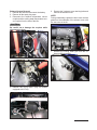
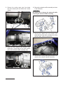
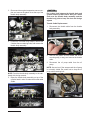
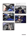
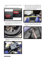
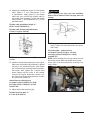
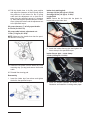
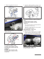
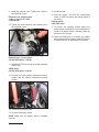
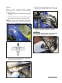
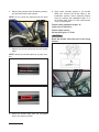
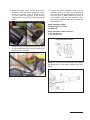
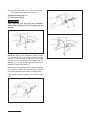
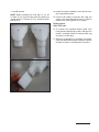
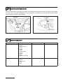
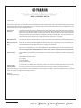
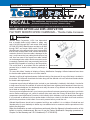
WAVERUNNER® WATERCRAFT
4/10/08
WR2008-001R
©2008 YAMAHA MOTOR CORPORATION, U.S.A.
RECALL
This modification has top priority. This bulletin must be
performed immediately to ensure customer safety.
NOTE: Bulletins that announce a recall will have an “R” at the end of the bulletin number from now on.
2003~2008 GP1300 and 2005~2008 VX1100
FACTORY MODIFICATION CAMPAIGN – Throttle Cable Corrosion
Yamaha Motor Corporation, U.S.A. has determined
that a possible defect which relates to safety may
exist in all 2003 through 2007 and certain 2008 model
GP1300 (GP1300R) WaveRunners and also in all 2005
through 2007 and certain 2008 model VX1100 (VX)
WaveRunners. In the affected units, there is a possibility
that the outer throttle cable could corrode and become
cracked or kinked. If the outer cable is damaged in this
way, it could cause the inner cable (throttle wire) to fray
over time from wear. If the frayed inner cable catches
on the damaged outer cable, throttle movement can be
increasingly impaired which may eventually lead to the
throttle being incapable of returning to the idle position.
This could result in an accident with the potential of
personal injury or death to the operator, passenger, or
bystanders.
GP1300 SHOWN
To correct this defect, Yamaha is initiating a Factory Modification Campaign. Affected watercraft must have
the throttle cable replaced with one of a new material.
Yamaha is notifying all registered owners of affected units by first-class mail. A copy of this letter is included in
this bulletin. The customer should take the letter along with the affected unit to an authorized Yamaha dealer
for throttle cable replacement.
A computer report listing all affected units invoiced to your dealership is included in this bulletin. Use the list
to help ensure all units are modified. All sold units that have been registered with Yamaha will show the customer’s name and address. Your dealership must notify the owner of any affected unit that was actually sold
but is listed as “unsold” on the report.
You must correct all affected units in your inventory, as well as all customer-owned units brought to you for this
service. Before modifying a unit, check for a black circle mark under the Primary ID label inside the engine
compartment (see Identification Procedure in this bulletin) which indicates a unit has already been modified.
If you purchase an affected unit from another dealer in the future, check for this black circle mark and then
perform the procedures in this bulletin if no mark is present before you sell the unit.
Affected WaveRunners should not be operated until they are modified. It is a violation of federal law and
Yamaha policy for your dealership to deliver any new affected units to customers until the procedures in this
bulletin are performed.
When the modification on each unit has been performed, follow the Warranty information section of this
bulletin to receive reimbursement. Be sure to use the Factory Modification Campaign procedures in
Chapter 8 of the Warranty and Y.E.S. Handbook (LIT-11760-00-05).
PAGE 1 of 20
Sold Units:
Modify all watercraft in the affected range. Before modifying a unit, check to be sure it has not
already been performed. See “Identification Procedure” in this bulletin.
Unsold
Units
Modify all affected units during unit set up and pre-delivery inspection.
Parts
Required:
Yes. Order the appropriate Throttle Wire Kit for each unit
Warranty:
Factory Modification Campaign. See the Warranty Information section of this bulletin.
Notify
Customers:
Yes. You must immediately contact any customer whose WaveRunner shows as unregistered
on the enclosed report. Yamaha has sent letters to customers whose WaveRunners were
registered for warranty as of 4/9/2008.
All 2003 GP1300-B (GP1300R)
All 2004 GP1300-C (GP1300R)
All 2005 GP1300-D (GP1300R)
All 2006 GP1300-E (GP1300R)
All 2007 GP1300-F (GP1300R)
2008 GP1300-G (GP1300R)
F1G-819301~821399
All 2005 VX1100-D (VX110 Sport)
All 2005 VX1100A-D (VX110 Deluxe)
All 2006 VX1100-E (VX110 Sport)
All 2006 VX1100A-E (VX110 Deluxe)
All 2007 VX1100-F (VX)
All 2007 VX1100A-F (VX Cruiser)
All 2007 VX1100B-F (VX Deluxe)
All 2007 VX1100C-F (VX Sport)
2008 VX1100-G (VX)
2008 VX1100A-G (VX Cruiser)
F1K-854101~868200
2008 VX1100B-G (VX Deluxe)
2008 VX1100C-G (VX Sport)
The throttle cable replacement procedures differ
between the two affected models. GP1300 procedures begin here. VX1100 procedures begin on
page 13.
GP1300
The following service procedure for the GP1300
appears lengthy, but it involves four basic jobs:
• Exhaust System Removal
• Intake Silencer Removal
• Throttle Cable Replacement
• Reassembly
PAGE 2 of 20
For details, refer to the GP1300R Service Manual
(LIT-18616-GP-00).
CAUTION:
To protect the watercraft from scratches, cover
the area around the engine compartment with a
clean cloth. Be sure to lift components out carefully as they are removed to avoid damage to the
deck or hull.
Exhaust System Removal
1. Remove the seat and disconnect the battery.
2. Remove all the spark plug caps.
3. Disconnect the exhaust temperature sensor
coupler and the cooling water temperature sensor coupler from the side of the box.
6. Remove the 3 exhaust cover retaining bolts and
remove the exhaust cover.
NOTE:
During reassembly, replace the bolt covers and the
gasket on the underside of the exhaust cover with
the new ones in the kit.
CAUTION:
Be careful not to damage the couplers while
disconnecting them.
7. Remove the cooling water pipe from the exhaust muffler assembly.
4. Loosen the exhaust joint screw clamp.
5. Remove the YPVS motor (only on models
equipped with YPVS).
PAGE 3 of 20
8. Remove the cooling water pipe from below
the outer exhaust joint and loosen the 2 screw
clamp.
10. Remove the exhaust muffler assembly as shown
in the illustration.
CAUTION:
Be careful not to damage the watercraft while
removing the exhaust muffler assembly.
2
3
1
4
2
5
1
11. Remove the 3 plastic ties on the inside of the
watercraft at the port side, and place the wiring
harness aside, inside the watercraft.
9. Slide the outer exhaust joint forward. Then,
loosen the 1 screw clamp on the inner exhaust
joint, at the exhaust muffler assembly side.
12. Remove the 4 cooling water pipes that are connected to the exhaust chamber assembly.
PAGE 4 of 20
13. Remove the exhaust chamber assembly as
shown in the illustration.
NOTE: To remove the bolt from the exhaust chamber assembly, use a socket with an overall length of
65mm (2.6 in).
Intake Silencer Removal
1. Loosen the 2 intake silencer pipe screw clamps
and remove the intake silencer pipe.
2. Remove the plastic tie from above the intake
duct and place the fuel hose aside. Then, loosen the intake duct retaining bolt and pull out the
intake duct upward.
65mm (2.6 in) SOCKET
14. Remove the gasket.
CAUTION:
To protect the exhaust manifold from dust or
foreign objects, cover it with a clean cloth.
PAGE 5 of 20
3. Disconnect the engine temperature sensor coupler and remove the plastic tie at the top of the
throttle body assembly.
CAUTION:
Put a clean cloth between the throttle body and
cylinder head to protect them. Also put a clean
cloth over the throttle body assembly and the
throttle body joint to keep out dust and foreign
objects
Throttle Cable Replacement
1. Disconnect the throttle cable from the throttle
body assembly.
4. Loosen the 3 throttle body clamps, remove the
2 intake silencer retaining bolts, and remove the
throttle body assembly.
2. Remove the plastic tie from below the YPVS
mounting stay (or stay) and remove the throttle
cable.
3. Disconnect the oil pump cable from the oil
pump.
NOTE: Use a mirror if the area around the oil pump
is not easily visible. Be careful not to drop the oil
pump cable retaining bolt.
NOTE: Push the throttle body assembly to the starboard side during removal.
5. Raise the throttle body assembly on top of the
cylinder head in order to make the throttle cable
visible.
PAGE 6 of 20
4. Remove the steering pad.
7. Pull up the 2 QSTS cables from the handlebar
side of the grommet.
NOTE: Pull out the QSTS cables until their
sponge portions are out of the grommet.
5. Disconnect the throttle cable from the throttle
lever.
8. From the inside of the watercraft, pull the throttle cable and take it out of the grommet on the
inside of the watercraft.
6. From the inside of the watercraft, remove the
plastic tie of the grommet on the inside the
watercraft.
PAGE 7 of 20
9. Replace the throttle cable with the new throttle
cable.
NOTE: Identify the part by its part number.
12. Replace the sponges of the 2 QSTS cables with
new parts and insert the sponges until they are
inside the grommet. Install the cables so that
their sponge portions are placed 300 mm (11.8
in) from the base of the QSTS grip.
300mm (11.8 in)
Previous: 60T5200
New: 60T5201
10. From the inside of the watercraft, insert the
throttle cable into the grommet and pull it out to
the handlebar side.
11. Apply grease to the throttle cable end, and then
temporarily connect the throttle cable to the
throttle lever.
PAGE 8 of 20
13. Make sure the end of the grommet facing the
inside of the watercraft has the proper shape.
Then, use a new plastic tie from the kit to secure
it in place.
14. Measure the installation length “A” of the throttle
cable. Adjust it if this measurement is out
of specification. Apply grease to the throttle
cable end, then connect the throttle cable to
the throttle body assembly. Tighten the throttle
cable locknut 1 and adjustment nut 2 to the
specified torque.
WARNING
After adjusting free play, turn the handlebar
side to side to make sure the free play does not
change.
Throttle cable installation length “a:”
18.5±1 mm (0.728±0.039 in)
Throttle cable locknut, adjustment nut:
11 Nm (1.1 kgf-m, 8.0 ft-lb)
a
17. Temporarily connect the oil pump cable to the oil
pump. Tighten the cable end bolt to the specified torque.
NOTE: Check that the cover 3 is securely
installed.
15. Install the throttle body assembly on the engine.
Make sure the throttle body assembly is placed
securely in the throttle body joint, then tighten
the 2 intake silencer retaining bolts to the specified torque. Next, tighten the 3 throttle body
screw clamps until the collar is fully seated.
Connect the engine temperature sensor coupler. Secure the wiring harness and the oil delivery hoses with a plastic tie.
Oil pump cable – cable end bolt:
1st stage 2.2 Nm (0.22 kgf-m, 1.6 ft-lb)
2nd stage 4.4 Nm (0.44 kgf-m, 3.2 ft-lb)
Loctite® 572
NOTE: When installing the oil pump cable, face the
flat surface of the cable end toward the oil pump.
Use a mirror if the area around the oil pump is not
easily visible.
Intake silencer retaining bolt:
1st stage 9.0 Nm (0.9 kgf-m, 6.5 ft-lb)
2nd stage 18 Nm (1.8 kgf-m, 13 ft-lb)
Loctite® 242
16. Adjust the throttle lever free play.
Throttle lever free play “a:”
4~7 mm (0.16~0.28 in)
PAGE 9 of 20
18. Pull the throttle lever to its fully open position
and adjust the clearance of the oil pump. Adjust
the positions of the locknut for the oil pump
cable and the adjustment nut so that the oil
pump has the specified amount of clearance
a. After attaining the specified amount of clearance, tighten the locknut and the adjustment nut
to the specified torque.
Intake duct retaining bolt:
1st stage 9.0 Nm (0.9 kgf-m, 6.5 ft-lb)
2nd stage 18 Nm (1.8 kgf-m, 13 ft-lb)
Loctite® 242
NOTE: Secure the fuel hose with the plastic tie
located above the intake duct.
Oil pump clearance a at fully open throttle:
0~0.5 mm (0~0.0197 in)
Oil pump cable locknut, adjustment nut:
11 Nm (1.1 kgf-m, 8.0 ft-lb)
NOTE: Make sure the throttle lever has the specified amount of free play.
2. Install the intake silencer pipe and tighten the
screw clamp to the specified torque.
Intake silencer pipe – screw clamp:
2.5 Nm (0.25 kgf-m, 1.8 ft-lb)
19. Install the new plastic tie from below the YPVS
mounting stay (or stay) and secure the throttle
cable.
20. Reinstall the steering pad.
Reassembly
1. Insert the intake duct from above and tighten
the bolt to the specified torque.
3. Install the exhaust chamber as shown in the
illustration and install the 4 cooling water pipes.
PAGE 10 of 20
4. Replace the gasket with a new part.
5. Install the muffler assembly as shown in the
illustration and install the 1 cooling water pipe.
4
3
5
2
4
NEW GASKET
1
5
No. 1 Bolt, No. 2 Bolt, No. 3 Bolt, No. 4 Bolt, No.
5 bolt:
1st stage 2.0 Nm (0.2 kgf-m 1.5 ft-lb)
2nd stage 39 Nm (4.0 kgf-m 28.8 ft-lb)
Loctite® 271
6. Secure the wiring harness to the watercraft with
3 new plastic ties from the kit.
7. Tighten the 1 screw clamp for the inner exhaust
joint to the specified torque.
NOTE: Exhaust manifold bolt must be installed with
Chamber assembly.
No. 1 Bolt, No. 2 Bolt, No. 3 Bolt:
1st stage 2.0 Nm (0.2 kgf-m 1.5 ft-lb)
2nd stage 39 Nm (4.0 kgf-m 28.8 ft-lb)
Loctite® 271
No. 4 Bolt:
1st stage 15 Nm (1.5 kgf-m 11 ft-lb)
2nd stage 35 Nm (3.5 kgf-m 25 ft-lb)
Loctite® 572
Inner exhaust joint – screw clamp:
1.5 Nm (0.15 kgf-m, 1.1 ft-lb)
8. Return the outer exhaust joint to its original
position. Install the cooling water pipe and tighten the 2 screw clamps to the specified torque.
Outer exhaust joint – screw clamp:
2.5 Nm (0.25 kgf-m, 1.8 ft-lb)
PAGE 11 of 20
9. Install the exhaust cover. Tighten the 3 bolts to
the specified torque.
Exhaust cover retaining bolt:
12 Nm (1.2 kgf-m, 8.7 ft-lb)
Loctite® 242
10. Tighten the screw clamp for the exhaust joint to
the specified torque.
15. Install the seat.
16. Start the engine, and use the multifunction
meter or YDIS to measure the trolling speed of
the engine.
Trolling speed:
1250~1450 r/min
17. To prevent the replaced throttle cable from
being reused inadvertently, break it with pliers to
render it unusable. Attach a warranty claim tag
and store it for 90 days.
18. When the modification is complete, put a black
circle with permanent marker under the Primary
ID label as shown in Identification Procedure.
Exhaust joint – screw clamp:
2.5 Nm (0.25 kgf-m, 1.8 ft-lb)
11. Install the YPVS motor (only on models equipped
with YPVS).
YPVS motor:
5.4 Nm (0.54 kgf-m, 3.9 ft-lb)
12. Connect the cooling water temperature sensor
coupler and the exhaust temperature sensor
coupler.
13. Install the spark plug caps.
14. Connect the battery cables.
NOTE: Make sure the battery band is installed
securely.
PAGE 12 of 20
VX1100
Refer to the VX1100 Service Manual
(LIT-18616-02-91), if necessary, when performing
these procedures.
4. Remove the upper handlebar cover; then, disconnect the throttle cable from the throttle
lever.
1. Remove the seat and disconnect the battery
terminals.
2. Open the front hood, remove the 4 plastic rivets,
and remove the storage compartment panel.
NOTE: To remove a rivet, push the rivet pin until it
is below the top surface of the rivet and makes a
sound.
THROTTLE
CABLE
STORAGE
COMPARTMENT
PANEL
5. Remove the upper handlebar holders, and
place the handlebar assembly to the side.
CAUTION:
To protect the watercraft from scratches, cover
the handlebar assembly with a clean cloth.
HANDLEBAR
HOLDERS
3. Disconnect the throttle cable from the accelerator position sensor assembly.
PAGE 13 of 20
6. Remove the grommet from the steering column,
and pull the throttle cable inboard.
NOTE: Do not reuse the grommet that has been
removed.
9. Apply water resistant grease to the throttle
cable end. Connect the throttle cable to the
accelerator position sensor assembly. Before
doing so, measure the installation length “A” of
the throttle cable. Adjust it if this measurement
is out of specification.
Throttle cable installation length “A”:
18.4±1 mm (0.72±0.04 in)
Throttle cable locknut:
6.5 Nm (0.65 kgf-m, 4.7 ft-lb)
CAUTION:
Route the throttle cable above the main wiring
harness.
GROMMET
7. Replace the throttle cable with the new throttle
cable.
NOTE: Identify the throttle cable by its parts number.
PREVIOUS: 6D31101
MAIN WIRING
NEW: 6D31102
8. Route the throttle cable from the corrugated
tube to the steering column.
PAGE 14 of 20
10. Route the throttle cable and the lead for the
handlebar switch assembly through the cutout
in the new grommet, which is included in the
kit. Then, install the grommet in the steering
column with its cutout facing starboard side as
shown.
11. Tighten the upper handlebar holders to the
specified torque and secure the handlebar in
place. Install each upper handlebar holder with
its punch mark a facing forward as shown in
the illustration. Set the front clearance b of
each upper handlebar holder narrower than the
rear clearance c.
Upper handlebar holder:
20 Nm (2.0 kgf-m, 14 ft-lb)
Loctite® 242
Upper handlebar holder clearance:
b 1.5 mm (0.06 in)
c 3.5 mm (0.14 in)
UPPER HANDLEBAR HOLDER
Install the new corrugated tube (included in kit)
on the throttle cable with its end touching the
end face of the grommet.
NOTE: Be sure to leave some slack in the handlebar switch lead 1 in the area a shown in the illustration.
PAGE 15 of 20
12. Connect the cable end to the throttle lever.
Then, adjust the throttle lever free play.
Throttle lever free play “A:”
4~7 mm (0.16~0.28 in)
WARNING
After adjusting free play, turn the handlebar
side to side to make sure the free play does not
change.
a
NOTE: As shown in the illustration, install the seal
1 into the groove in the bracket. Pull the throttle
cable 2 in the direction of the arrow, and install
the seal end 3 around the inner cable. Turn the
adjuster 4 in or out until the specified free play is
obtained. Tighten the locknut 5.
Make sure the accelerator position sensor assembly
cam comes in contact with both the fully open and
fully closed stoppers and makes a clicking sound.
Apply water resistant grease to the throttle cable
end.
PAGE 16 of 20
13. Install the pad.
NOTE: Before installing the long pad a, cut off
57.8mm (2.3 in) from its lower end, thus setting its
overall length to 139.4mm (5.5 in). Install the short
pad b as is.
14. Install the upper handlebar cover and the storage compartment panel.
15. Connect the battery terminals and start the
engine. Use the multifunction meter or YDIS to
measure the trolling speed of the engine.
Trolling speed:
1550~1750 r/min
b
a
16. To prevent the replaced throttle cable from
being reused inadvertently, break it with pliers to
render it unusable. Attach a warranty claim tag
and store it for 90 days.
17. When the modification is complete, put a black
circle with permanent marker under the Primary
ID label as shown in Identification Procedure
PAGE 17 of 20
When the modification is complete, put a black circle with permanent marker under the Primary ID label which
will make it easy to identify a modified unit. If you encounter an unfamiliar unit, check first for this mark before
performing the procedures in this bulletin.
GP1300
VX1100
PID LABEL
PID LABEL
BLACK
CIRCLE
BLACK CIRCLE
Part Number
Description
Application
Dealer Cost
90891-40753-00
F1G Wire Kit
Contents:
1 Cable, Throttle
3 Cover
3 Gasket
1 Clamp
1 Gasket, Muffler
Damper
4 Clamp
2 Clamp
2 Water Proof Packing
GP1300
$33.78
90891-40752-00
F1K Wire Kit
Contents:
1 Wire Throttle 1
1 Plug
1 Tube
VX1100
$12.73
PAGE 18 of 20
The owner of each warranty-registered unit will receive a letter announcing this campaign. The letter has a
label which includes the Primary ID and Recall Number.
The modification is authorized for all affected WaveRunners, both sold and unsold, regardless of ownership
or warranty status. You do not need the customer’s letter to perform the modification or to file for reimbursement.
After modification, submit a Recall Request using Recall Number 990046. Choose the status “M.” You will
be reimbursed as follows:
GP1300
You will be reimbursed for the appropriate throttle wire kit, plus your normal handling fee, and 3.6 hours of
labor.
VX1100
You will be reimbursed for the appropriate throttle wire kit, plus your normal handling fee, and 1.0 hour of
labor.
YDS
When signed on to YDS, click on the Service Tab, and then “Recall Request-Add.” The system will check your
submission instantly to make sure the Primary ID numbers you’ve entered are valid for the recall. You can
check back the next day for your claim numbers to track your credit. This function also allows you to enter
multiple Primary IDs for the same recall.
MAIL
Complete a recall Reimbursement Request (LIT-11790-00-03) as shown below:
9 9 0 0 4 6
F 1 K
0 8 5 4 X X X
0 4
1 5
2 0 0 8
If you have any questions about proper procedures for Factory Modification Campaigns, see Chapter 8 in
your Warranty and Y.E.S. Handbook (LIT-11760-00-05).
PAGE 19 of 20
SAFETY RECALL NOTICE
April 10, 2008
Dear Yamaha WaveRunner® Owner:
Yamaha Motor Corporation, U.S.A. has determined that a possible defect which relates to safety may exist in all 2003 through 2007 and certain
2008 model GP1300 (GP1300R) WaveRunners and also in all 2005 through 2007 and certain 2008 model VX1100 (VX) WaveRunners. Our
records indicate that you own one of these watercraft.
The reason for
this recall:
In the affected watercraft, there is a possibility that the outer throttle cable could corrode and become cracked or
kinked. If the outer cable is damaged in this way, it could cause the inner cable (throttle wire) to fray over time from
wear. If the frayed inner cable catches on the damaged outer cable, throttle movement can be increasingly impaired
which may eventually lead to the throttle being incapable of returning to the idle position. This could result in an accident with the potential of personal injury or death to the operator, passenger, or bystanders.
What Yamaha and
your dealer will do:
Your dealer will replace the throttle cable with one of a new material. This service will be performed without cost to
you for parts or labor.
What you should do
now:
Please call your authorized Yamaha WaveRunner dealer to make a service appointment to have this procedure performed. Remember to take this letter with you when you take in your watercraft.
For the name of a dealer near you, call 1-800-88-YAMAHA or visit the Yamaha web site at: www.yamaha-motor.com.
You should not operate the Yamaha WaveRunner shown above until this inspection/correction is performed.
If you need help:
If, after contacting your dealership, you have questions or concerns which the dealership is unable to answer, please
write to:
Yamaha Motor Corporation, U.S.A.
Customer Relations Department
P.O. Box 6555
Cypress CA 90630
or call 1-800-962-7926.
If you no longer
own this Yamaha:
If you have sold your WaveRunner to another party, please call us toll-free at 1-800-227-5963 with the name and address of the new owner, along with the serial number shown next to your name on the address label above.
We’re sorry to cause you any inconvenience, but we are sincerely concerned about your safety and continued satisfaction with our products.
Thank you for giving your attention to this important matter.
Sincerely,
Customer Support Group
Yamaha Motor Corporation, U.S.A.
PAGE 20 of 20