1
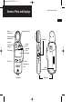
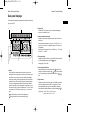
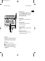
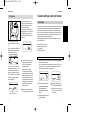
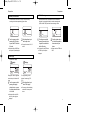
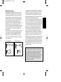
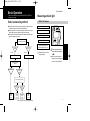
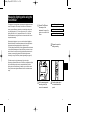
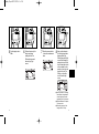
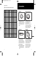
AutoMeter_VF.qxd 02.7.8 1:31 PM ページ 1 Instruction Manual Please read this manual thoroughly before using this product. AUTO METER VF AutoMeter_VF.qxd 02.7.8 1:31 PM ページ 2 Thank you for purchasing the MINOLTA AUTO METER VF. The MINOLTA AUTO METER VF offers the following features: ● Exposure meter with a built-in microprocessor for flash light and ambient light measurements for a broad range of shooting conditions ● Separate measurement modes for flash light and ambient light, for calculating and displaying the proportions of flash light and ambient light. ● Memory function for storing two measurement values, Averaging function to calculate the average of two stored measurement values, and a Brightness Difference function to display a measurement value in terms of its difference to a specified reference value. ● Calculation functions for shadow-based exposure and highlight-based exposure readings for reflected-light readings with attachments such as a Viewfinder. ● (Alt) mode for "custom settings" to allow users to customize special settings, such exposure correction value and number of shutter speed stops. ● Measurement values are displayed both in analog and digital format on the display of the meter, for easy-to-read, error-free visually reading. Safety Warnings and Cautions To ensure proper use of the instrument, take special care to observe the following handling instructions when using this instrument. Read this instruction manual carefully and keep it securely in a place where you can refer to it readily. WARNING indicates a danger that improper use of the instrument will lead to the death or serious injury of the user ● Do not use the instrument in a place where inflammable or combustible vapors (e.g. gasoline) are present. Otherwise there is a risk of causing a fire. ● Do not throw batteries into fire. Do not recharge (non-rechargeable batteries), short circuit, heat or disassemble batteries. Otherwise, there is a risk of causing fire or injury due to an explosion or fluid leakage. ● Never attempt to disassemble or modify the instrument yourself. Otherwise there is a risk of causing fire or electric shock. AutoMeter_0704_rw2.qxd 02.7.8 0:02 PM ページ 4 CAUTION indicates a danger that improper use of the instrument will lead to injury to the user or to property damage ● Do not use any batteries other than those designated for use with the instrument. Do not mix new batteries and old batteries, or batteries of different types. When fitting batteries, make sure to align them according to the polarity shown on the instrument (plus "+" and minus "-"). Otherwise there is a risk that the batteries may leak or become damaged, leading to fire, injury or pollution of the surrounding environment. ● Do not place the meter in an unstable place, such as a shaky table or tilted surface. Otherwise there is a risk that the instrument may fall or topple, causing injury. In addition, take care not to drop the instrument while carrying it. Table of Contents Names of Parts and Displays ............................................................................2 ● Data panel displays ......................................................................................4 Preparations ........................................................................................................8 ● Battery ........................................................................................................8 1. Preparing .................................................................................................8 2. Inserting ...................................................................................................8 3. Checking ...............................................................................................10 ● Custom settings mode (Alt mode) ...............................................................11 1. Alt mode..................................................................................................11 ● Setting film speed ........................................................................................14 ● Selecting the measuring method ................................................................15 1. Incident-light readings ...........................................................................15 2. Reflected-light readings .........................................................................17 * Difference between incident-light and reflected-light readings ....................18 Basic Operation ...............................................................................................22 ● Select a measuring method.........................................................................22 ● Measuring ambient light ..............................................................................23 1. With a still camera ..................................................................................23 2. With a cine camer...................................................................................27 ● Measuring flash light ..................................................................................30 1. With a sync cord ....................................................................................30 2. Without a sync cord ...............................................................................35 * Measuring the proportion of flash light and ambient light ............................39 Special Functions .............................................................................................41 ● Memory function ........................................................................................41 ● S/A/H (Shadow/Average/Highlight) calculations.........................................43 ● Brightness difference function ....................................................................49 * Measuring lighting ratio using the Flat Diffuser............................................54 * Using as a simplified illuminance meter.......................................................59 Accessories .....................................................................................................61 Care and Storage...............................................................................................63 1. Care ............................................................................................................63 2. Storage .......................................................................................................63 Handling Instructions ......................................................................................64 ● After service ...............................................................................................65 Specifications ....................................................................................................66 1 AutoMeter_VF.qxd 02.7.8 1:31 PM ページ 2 Names of Parts and Displays Names of Parts and Displays Diffuser mounting index S/A/H button Receptor mounting index Up/down key Accessoryreceptor jack (with cap) Memory button Measuring button Power button Data panel ISO button Mode button Display-selector button Sync terminal 2 Battery chamber cover Strap eyelet 3 AutoMeter_VF.qxd 02.7.8 1:31 PM ページ 4 Names of Parts and Displays Names of Parts and Displays Data panel displays For the purpose of explanation, the diagram below shows all indicators that light up on the LCD. 1 2 2. Analog scale Pointers mark FNo. (f-number) values. F-numbers are displayed by pointers, to the nearest 0.5 stops. 3. Shutter speed/frame rate display Displays the current shutter speed or frame rate, which is set with the up/down key. When shutter speed is between [1 stop: 1 sec., 1/2 stop: 0.7 sec., 1/3 stop: 0.6 sec.] and 45 sec., s is displayed; between 1 min. and 30 min., m is displayed. Setting range: Shutter speed: 30 min. to 1/8000 sec. (1, 1/2, 1/3 stops) Frame rate: 8 to 128 f/s 4 4. Film speed display Displays the film speed, which is set using the ISO button and up/down key. Alt is displayed when the meter is in mode. 5 6 3 1. Pointers Pointers light up to indicate measurement values (f-number) on an analog scale. When using the memory function or other functions, up to four pointers can be lit up at the same time, indicating two readings in memory (two pointers), the average of these two values, and the latest measurement value. The small digit to the right of the two-digit reading (f-number) on the digital readout indicates a fractional value between stops. The value shown on the analog display is rounded down or up to the nearest 0.5 stops (0.2 stops is rounded down to 0, 0.3 and 0.7 stops are rounded to 0.5, and 0.8 stops is rounded up to 1, i.e. the next full stop). lights up if a reading is under the meter's display range. Setting range: ISO 3 to 8000 5. Over-/under-range indicators When a reading is over the meter's display range, blinks. When a reading is under the meter's display range, blinks. When a reading is over or under the display range, the display units (FNo.) and or blink. 6. Digital readout Displays the f-number (when display units are set to FNo.) or exposure value (when display units are set to EV), in increments of 0.1 stops. When measuring flash light, only the f-number (FNo.) is displayed. When measuring brightness difference, readings are displayed in ▲ EV. Display range: f-number (FNo.) 1.0 to 90+0.9 stops Exposure value (EV) -7.8 to 31.5 lights up if a reading is over the meter's display range. 4 5 AutoMeter_VF.qxd 02.7.8 1:31 PM ページ 6 Names of Parts and Displays Names of Parts and Displays 8 7 9. Measuring mode indicators Press the mode button repeatedly to select and display one of the three measuring modes: AMBI, CORD or NON CORD. The measuring mode changes in the following order each time the mode button is pressed: AMBI ➞ CORD ➞ NON CORD ➞ AMBI ... 10.Reflected-light indicator This indicator lights up when you use a reflected-light attachmentⅡ or Viewfinder 5°. 11.Quadrant proportion indicator This indicates the approximate proportion of flash light in the total exposure when measuring flash light. 13 10 11 9 12 12.Flash light measuring indicator This indicator lights up during measurement in CORD mode and NON CORD mode. 13.Brightness difference function indicator This indicator lights up when you press the S/A/H button. For details of the brightness difference function, see page 49. 7. Memory indicator When you press the memory button to store a reading in memory, one of these dots lights up. If one reading is stored in memory, one dot is displayed; if two readings are in memory, two dots are displayed. 8. S/A/H indicators : This lights up when you press the S/A/H button. : S or H can be selected by using the up/down key while holding down the S/A/H button during reflected-light readings. Select to measure the exposure of shadow areas; select to measure highlight areas. / 6 7 AutoMeter_VF.qxd 02.7.8 1:31 PM ページ 8 Preparations Preparations Battery 1. Preparing The instrument uses a single AA dry cell. ● Manganese dry cell (R-6) ● Alkaline-manganese dry cell (LR-6) ● Nickel-cadmium rechargeable battery ● Lithium-manganese dry cell ● Nickel-manganese dry cell Any one of the above types of batteries can be used. 2. Inserting 1 8 Remove the battery chamber cover by sliding it lightly in the direction of the arrow. 2 Insert the battery with the plus (+) and minus (-) ends oriented according to the diagram in the battery chamber. 3 Replace the battery chamber cover. ★ The meter will not work if the battery is inserted in the wrong direction. 9 AutoMeter_VF.qxd 02.7.8 1:31 PM ページ 10 Preparations Preparations Custom settings mode (Alt mode) 3. Checking If you turn the power on when there is not enough battery power to take measurements, or if the battery runs low during measurement, a blinking "bo" will display for approx. 1 min. and then the display will switch off. If this happens, replace the battery with a new one. The instrument automatically checks the battery when power is on. After a new battery is installed, the display appears as shown below after the power is turned on. 1. Alt mode To adjust the meter's operation settings to your preferences, set the meter to Alt mode by pressing the power button while holding down either the ISO button, display-selector button, mode button, or measuring button. Once in Alt mode, you can switch setting modes by using the ISO button, display-selector button, mode button or measuring button, and you can change setting values using the up/down key. After specifying your desired value, confirm the setting by turning the power off and then on. 1) Exposure correction value 2) Shutter speed increments 3) FNo. display 4) TIME/CINE setting 1) Exposure correction value If you turn on the meter when the battery power is running low, "bc" and a battery level indicator will appear on the display for approx. 0.5 sec. before the normal display appears. If this display appears, replace the battery. ● To conserve battery power, the meter automatically switches itself off if no operation has been performed for approximately 10 minutes. To commence measurement when the display is switched off, press the power button. (At this time, all settings for film speed, shutter speed, measuring mode and display units are saved, but the last reading and values in memory are lost.) ● When you replace the battery all initial settings are preserved. Battery level indicator This sets the exposure correction value. The set value is displayed when you turn the power on. You can adjust this setting to recalibrate the meter to your choice of exposure values, or when you want to calibration more than one exposure meter to the same exposure range. 1 Turn the power on while pressing the measuring button, or press the measuring button in Alt mode. 2 Use the up/down key to set the correction value. ♦ Display changes in increments of 0.1Ev. You can set the value up to ±10.0Ev. ♦ Alt is displayed bottom left and Ev0.0 is displayed. 10 11 AutoMeter_VF.qxd 02.7.8 1:31 PM ページ 12 Preparations Preparations 4) TIME/CINE setting 2) Shutter speed increments Switches between shutter speed and frame rate in AMBI mode Note that it is not possible to switch to another measuring mode (CORD or NON CORD) while the frame rate setting is active. Choose between increments of 1/2-stop, 1/3-stop and 1-stop, according to the shutter speed settings your camera. 1 Turn the power on while pressing the ISO button, or press the ISO button in Alt mode. 2 Use the up/down key to set the step value. ♦ Choose from values of 1.0, 0.5 and 0.3. ♦ Alt (bottom left) and TIME step value (center left) are displayed. 1 Turn the power on while pressing the mode button, or press the mode button while in Alt mode. ♦ Alt (bottom left) and TIME value or CINE f/s (center left) are displayed. 2 Use the up/down key to set the shutter-speed or frame rate value you desire. ♦ Choose mode from TIME and CINE. 3) FNo. display Specifies FNo. display display display Displays FNo. with one digit after the decimal point to indicate 1/10 stops. For quickly reading values between f-numbers (e.g F3.5, F4.5) 1 2 Turn the power on while pressing the displayselector button, or press the display-selector button in Alt mode. ♦ Alt (bottom left) and an FNo. value of 0 (center right) are displayed. 12 Use the up/down key to select FNo. display. ♦ Choose your preferred display method from the two options above. 13 AutoMeter_VF.qxd 02.7.8 1:31 PM ページ 14 Preparations Setting film speed Preparations Selecting a measuring method You can choose between two measuring methods—incident-light reading and reflected-light reading, according to the shooting conditions or purpose of the image. To set the film speed, use the up/down key while holding down the ISO button. ● Each time you press , the film speed increases by 1/3-stop. Holding down the button increases the value continuously. Even if you continue pressing , the maximum setting is ISO 8000. ● Each time you press , the film speed decreases by 1/3-stop. Holding down the button decreases the value continuously. Even if you continue pressing , the minimum setting is ISO 3. ● Be sure to set film speed to the correct setting, since all measurement results are based on the set value. ● If you change the film speed after you take a measurement, the reading will be recalculated and displayed accordingly. 14 When used with its various accessories, the MINOLTA AUTO METER VF can perform exposure measurements in either of these two ways. To perform an incident-light reading, the AUTO METER VF is used with the Spherical Diffuser, Mini receptor or Flat Diffuser. To perform a reflectedlight reading, the meter is used with the Viewfinder 5° (acceptance angle of 5°) or reflected-light attachment (acceptance angle 40°). ● The Spherical Diffuser for incident-light readings is supplied as a standard accessory with the AUTO METER VF. ● Accessories other than the Spherical Diffuser are sold separately. (See page 61.) 1. Incident-light readings When performing incident-light readings, use the Spherical Diffuser for three-dimensional subjects such as portraits, and architectural or landscape photographs. Use the Flat Diffuser when you photograph flat surfaces such as documents or paintings, or when you want to measure lighting ratio (See page 54.). When you want to photograph small threedimensional objects, use the Mini receptor, which enables readings of minute objects. 15 AutoMeter_VF.qxd 02.7.8 1:31 PM ページ 16 Preparations Preparations 2. Reflected-light readings To use a meter for reflected-light measurements, you need to use one of the attachments for reflected-light measurements (40° acceptance angle). The exposure is based on the average of the light reflected from all subjects within the meter's field of view (approximately 40°). If you need to do selective metering or take spot measurements of specific parts of a subject, use the Viewfinder 5° (5° acceptance angle). (See page 20.) ● To attach and detach these accessories, follow the same procedure as described for the Spherical Diffuser. (Attach and detach devices by rotating the holder (ring).) Attaching the Spherical Diffuser Align the white dot on the diffuser with the index on the meter receptor head, push the diffuser into the receptor head, and turn the diffuser clockwise until it stops. (To connect the Mini receptor, insert its plug into the accessoryreceptor jack.) Removing the Spherical Diffuser Vertical mounting Horizontal mounting Rotate the diffuser anticlockwise until it stops, and pull the diffuser to detach it. To take a reflected-light reading, aim the meter's receptor head from the camera position so that it reads the area you want to measure. ● The receptor can rotate through a range of 270 degrees, so that you can use the meter in an almost any photographic configuration. To take an incident-light reading, position the meter near the subject and aim the Spherical Diffuser directly at the camera. ● The receptor can rotate through a range of 270 degrees, so that you can use the meter in an almost any photographic configuration. 16 17 AutoMeter_VF.qxd 02.7.8 1:31 PM ページ 18 Difference between incident-light and reflected-light readings Exposure can be measured in two basic ways. One way is to measure the light incident on the subject, i.e. the brightness of light illuminating the subject (illuminance) (see Fig. 1); the other is to measure the light reflected by the subject, i.e. the intensity of the light reflected from the subject in the direction of the camera (luminance) (see Fig. 2). Fig. 1 Incident-light method Light source Fig. 2 Reflected-light method Light source Thus, incident-light readings are based on this standard value of 18% reflectance. This means that areas of subjects having a reflectance higher than 18% will turn out brighter (e.g. white), while areas of reflectance lower than 18% will turn out darker (e.g. black). This will produce a clear contrast in the picture of the subject. From this, we can see that this measuring method provides for natural tonal range over the entire composition. Also, since people (skin) have an overall reflectance of around 18%, this method is suitable for reproducing human skin tones. For this reason, incident-light readings are good for portrait photography, where presentation of skin tones is important. * The value of “18%” has been determined to be a typical reflectance value for many different subjects. Incident-light Fig. 3 (a) Reflected-light (b) Camera Camera Before selecting the most suitable measuring method, you need to fully understand the different sources of light you are working with, as well as the influence of the positions and direction of receptors during measurement. \Incident-light readings In general photography, light from the illuminating light source reflects off the subject and passes through the lens to form an image on the film, and to expose the film. To accurately calculate exposure in incident-light readings, you need to know how much of the illuminating light is actually reflected from the object to the camera. To do this, you need to know how light or how dark the subject is, i.e. the reflectance of the subject. Since a typical value of reflectance for many scenes is 18%*, this value is used to calculate the quantity of light reflected from the subject towards the camera. The exposure reading (f-number and shutter speed) are then calculated to reproduce the metered area as a midtone with 18% reflectance. 18 Threedimensional subjects Flat subjects To make effective incident-light exposure readings, you must use the Spherical Diffuser and Flat Diffuser creatively. When photographing three-dimensional objects such as people, the highlights and shadow areas of a composition depend on the direction of the main illuminating light source. Exposure is also influenced by any light reflected towards the camera from the sides or rear of the subject (Fig. 3 (a)). In these situations, the Spherical Diffuser captures the illuminating light coming from different directions at the position of the subject, so that the exposure reading takes into account the contribution of this light on illuminating the subject. On the other hand, with flat subjects such as pictures and documents, light from the sides or rear of the subject generally make little or no contribution to illuminating the subject (Fig. 3 (b)). So, for these situations, accurate exposure readings are made using a Flat Diffuser to capture only the illuminating light from the front of the subject. 19 AutoMeter_VF.qxd 02.7.8 1:31 PM ページ 20 Reflected-light readings Reflected-light exposure readings directly measure the amount of light (luminance) reflected from the subject to the camera. Unlike the case of incident-light readings, this method does not rely on the assumption of a standard subject reflectance of 18%. Based on the measured amount of light falling on the subject, the meter calculates the appropriate exposure value for reproducing the subject on film at a suitable medium density (midtone). This means that in reflected-light readings, all subjects, regardless of their reflectance, i.e. regardless of whether they are bright or dark (white or black), will be reproduced at the same tonal density (midtone). For this reason, when making reflected-light exposure readings, it is important to decide which area of the subject to measure, since the reflectance will generally vary quite widely over the composition under different conditions. There are two basic methods for making reflected-light exposure readings. These methods use different distances and angles between exposure meter and subject. One method is "averaging metering," where the exposure of the entire composition is measured (Fig. 4). The other is selective metering," where illumination is measured only for a specific part of the composition (Fig. 5). Fig. 4 Averaging metering Fig. 5 Selective metering In averaging metering, all the reflected light from the entire subject that fits within the field of view of the meter is measured using a receptor with a relatively wide acceptance angle. If the average reflectance of the entire subject is close to 18%, the exposure reading will be close to the value produced by an incident-light reading. For this kind of situation, this is the fastest and easiest kind of reflective-light reading to make. However, if there is a large bright or dark area within the camera's field of view, or if there is any backlighting, these factors may cause the exposure reading to be too high or too low. So, caution is needed in these situations. In selective metering, measurements are taken so that only light reflected from a specific, selected part of the subject falls within the acceptance angle of the meter. This is achieved by using a receptor with a narrow acceptance angle, or by placing the receptor sufficiently close to the subject. Since the meter is not affected by light from other parts of the composition, the selected part of the subject is reproduced on film at a suitable tonal density. When the measured part has a normal reflectance, e.g. human skin, then, as in the case of averaging metering, the exposure reading will give a very similar result to incident-light reading. Thus, for photographing subjects of normal reflectance, such as people, this method offers highly accurate exposure readings. However, this method can cause problems if you selectively measure very bright (high reflectance) or very dark (low reflectance) subjects, because the meter assumes that the whole image should have the same tonal density as the selected area. So take special care about which part of a subject you select to measure when using selective metering. There are various advanced selective area metering methods, such as the highlight standard exposure method, where an exposure reading is taken of a bright (white) part of the composition; the shadow standard exposure method, where a dark (black) part of the composition is measured; and a method for determining exposure by evaluating the contrast of the subject and then forecasting how it will come out on film. To make full use of selective metering, refer to specialist books and photo magazines. You will find that selective metering can give you very precise control over exposure. 20 21 AutoMeter_VF.qxd 02.7.8 1:31 PM ページ 22 Basic Operation Basic Operation Here we explain the basics of using the MINOLTA AUTO METER VF to take exposure readings. Select a measuring method ● Flash light refers to artificial momentary lighting from light sources such as electronic flashes, strobe flashes, and speed lights. ● Ambient light refers to continuous lighting from sources such as natural light (sunlight) and electric lights (including fluorescent lights). ● In either case, both incident-light exposure readings and reflected-light exposure readings can be made. Are you using a still camera? Are you using a cine camera? With a still camera With a cine camera Alt mode Select CINE Type of light source to measure Ambient light 1. With a still camera Battery (p. 8) ↓ Shutter speed increments (p. 12) ↓ FNo. display (p. 12) ↓ Film speed (p. 14) ↓ Incident-light reading and reflected-light reading (p. 15) 1 Alt mode Select TIME Measuring ambient light Prepare the meter to start taking readings. 2 Press the mode button to switch the mode display to AMBI. ● When the measuring mode is changed, previous readings and values in memory are deleted. Flash light (mixed light) Are you using a sync cord? AMBI mode (p. 23) 22 With a sync cord Without a sync cord CORD mode (p. 30) NON CORD mode (p. 35) AMBI mode (p. 23) * Refer to page 34 for details on metering M flashbulbs. 23 AutoMeter_VF.qxd 02.7.8 1:31 PM ページ 24 Basic Operation Basic Operation Display example Dispaly units are FNo. 3 Use the up/down key to set the desired shutter speed. ● Shutter speed can be set within the range of 30 min. to 1/8000 sec. ● Each time you press , the shutter speed increases. Holding down increases the value continuously. The shutter speed cannot be increased to above 1/8000 sec., even if you continue pressing. ● Each time you press , the shutter speed decreases. Holding down decreases the value continuously. The shutter speed cannot be decreased to below 30 min., even if you continue pressing. ● The shutter speed can also be changed after meter readings. 24 4 Press the display-selector button to set the exposure display units to FNo. or EV. 5 Press the measuring button to take readings. ● The meter will continue to take readings as long as the measuring button is held down. As readings are taken, the results are displayed on the digital readout in the units set in step 4. ● When you release the measuring button, the meter stops taking measurements and the last reading will remain on the digital readout. If you set your desired shutter speed, the f-number required for proper exposure at that shutter speed is displayed on the digital readout. The reading is also displayed on the analog scale by a pointer ( ). Ex.: The display shows a reading of F4.0+0.2-stops. If the exposure reading is outside the display range of the meter, the f-number is not displayed. Instead, FNo. and (over) or (under) will blink to indicate that the reading is out of range. The or indicator on the analog scale will also blink. If the reading is over the display range, reset the shutter speed to a faster value; if it's under the display range, reset to a slower shutter speed. In this way, you will be able to determine an appropriate combination of shutter speed and f-number. 25 AutoMeter_VF.qxd 02.7.8 1:31 PM ページ 26 Basic Operation Basic Operation 2. With a cine camera Battery (p. 8) ↓ CINE (p. 13) ↓ Film speed (p. 14) ↓ Incident-light reading and reflected-light reading (p. 15) Display units are EV If the reading is outside the measurement range of this meter, E (error) will be displayed on the digital readout, and (over) or (under), and or on the analog scale, will blink to indicate that the measurement is out of range. The exposure is displayed in units of EV (exposure value), regardless of the shutter speed setting. Shutter speed, the analog scale and the pointers along the analog scale are shown in the same way as when the meter is set to FNo. display. Ex.: The display shows a reading of 10.2 (EV). The shutter speed and FNo. corresponding to the shutter speed are displayed on the analog scale. 1 Prepare the meter to start taking readings. 2 In CINE mode, the measuring mode is fixed to AMBI. ● Measuring mode cannot be changed. If the reading is outside the measurement range of this meter, E (error) will be displayed on the digital readout, and (over) or (under), and or on the analog scale, will blink to indicate that the measurement is out of range. 26 27 AutoMeter_VF.qxd 02.7.8 1:31 PM ページ 28 Basic Operation 3 Use the up/down key to set the frame rate of the camera you are using. ● Eight frame rates can be set: 8, 12, 16, 18, 24, 25, 30, 32, 64, and 128 frames/sec. (The appropriate shutter speed, corresponding to a shutter opening of 180°, is set automatically by the exposure meter.) Basic Operation If the opening of your camera's shutter is not 180°, the film speed should be adjusted as follows. Shutter opening and film speed adjustment Shutter opening Film-speed adjustment 160° -1/3 220° +1/3 -1/3: Set the film speed to 1/3stop slower than the film speed you are using. (Ex.: ISO 500 to 400) +1/3: Set the film speed to 1/3stop faster than the film speed you are using. (Ex.: ISO 500 to 640) 4 Press the display-selector button to set the exposure display units to FNo. or EV. ● When the meter is set to display in EV, FNo. is also displayed on the analog scale. 5 Press the measuring button to take readings. ● The meter will continue to take readings as long as the measuring button is held down. As readings are taken, the results are displayed on the digital readout in the units set in step 4. Readings are displayed on the analog scale at the same time. * Display example is the same as the case of a still camera. (Refer to page 25.) 28 29 AutoMeter_VF.qxd 02.7.8 1:31 PM ページ 30 Basic Operation Basic Operation Measuring flash light 1. With a sync cord Battery (p. 8) ↓ Shutter speed increments (p. 12) ↓ FNo. display (p. 12) ↓ Film speed (p. 14) ↓ Incident-light reading and reflected-light reading (p. 15) 1 30 Prepare the meter to start taking readings. 2 Press the mode button to switch the mode display to CORD. ● When the measuring mode is changed, previous readings and values in memory are deleted. ● Settings for shutter speed and display units are automatically adjusted as follows. 1/640 to 1/8000 sec.: adjusted to 1/500 sec. 1.3 sec. to 30 min.: adjusted to 1 sec. EV: adjusted to FNo. 3 Attach the flash sync cord to the meter's sync terminal. ★ Take care when connecting the flash to the meter, as the flash may fire. 4 Use the up/down key to select the shutter speed of your camera. ● Shutter speeds can be set within the range of 1 sec. to 1/500 sec. (The speed can be set within the flash sync speed range of your camera.) ● Each time you press , the shutter speed increases. Holding down increases the value continuously. The value cannot be increased above 1/500 sec. even if you continue pressing. ● Each time you press , the shutter speed decreases. Holding down decreases the value continuously. The value cannot be decreased below 1 sec. even if you continue pressing. 31 AutoMeter_VF.qxd 02.7.8 1:31 PM ページ 32 Basic Operation Basic Operation Display example 5 Press the measuring button to take a reading. ● The flash light is released and the meter takes a single reading and displays the result on the digital readout. The reading is also displayed on the analog scale. The proportion of flash light illuminating the composition is shown on the quadrant proportion indicator. ● If there is no flash connected to the sync terminal, the meter measures and displays the exposure for ambient light only. ★ After confirming that the flash is completely recharged, take a reading. ★ If you change the shutter speed setting after taking a flash light reading, the FNo. and quadrant proportion indicator will change accordingly. 32 The f-number corresponding to the shutter speed set in step 4 is displayed on the digital readout as well as on the analog scale. The proportion of flash light illuminating the composition is shown on the quadrant proportion indicator. Ex.: The display shows an fnumber reading of F8.0+0.9stops. If the reading is outside the measurement range of the meter, E (error) will be displayed on the digital readout, and (over) or (under), and or on the analog scale, will blink to indicate that the measurement is out of range. If the exposure reading is outside the display range of the meter, the f-number is not displayed. Instead, FNo. and (over) or (under) will blink to indicate the reading is out of range. The or indicator on the analog scale will also blink. 33 AutoMeter_VF.qxd 02.7.8 1:31 PM ページ 34 Basic Operation Basic Operation 2. Without a sync cord ★ When measuring flash light using a sync cord (CORD mode), the flash may fail to fire (e.g. if the trigger voltage of the flash is too low). In this case, take a reading without sync firing the flash (NON CORD mode). ★ Taking readings of M-bulb flash guns: 1. Prepare the meter to start taking readings. 2. Press the mode button to switch the mode display to CORD. 3. Connect the meter to the flash gun by attaching a sync cord to the meter's sync terminal. 4. Set a shutter speed that allows all the light of the flashbulb to be measured. This can be achieved by setting the speed to below 1/15 sec. 5. Press the measuring button to take a reading. ● Take special care to use CORD mode for metering flashbulb light. Flashbulb light cannot be measured in NON CORD mode due to the light emission characteristics of flashbulbs. ● When taking your photographs, set the sync contact to "X" and shoot at the same shutter speed as set in step 4. ● Use flashbulbs with consistent emission characteristics. 34 Battery (p. 8) ↓ Shutter speed increments (p. 12) ↓ FNo. display (p. 12) ↓ Film speed (p. 14) ↓ Incident-light reading and reflected-light reading (p. 15) 1 Prepare the meter to start taking readings. 2 Set the mode display to NON CORD using the mode button. ● When the measuring mode is changed, previous readings and values in memory are deleted. ● Settings for shutter speed and display units will be automatically adjusted as follows. 1/640 to 1/8000 sec.: adjusted to 1/500 sec. 1.3 sec. to 30 min.: adjusted to 1 sec. EV: adjusted to FNo. 35 AutoMeter_VF.qxd 02.7.8 1:31 PM ページ 36 Basic Operation Basic Operation ● If the flash does not fire within approx. one minute after the meter goes into flash waiting mode, or if you press any button other than the measuring button during this time, the NON CORD mode symbol will stop blinking (stay on). Then, even if you fire the flash, no reading will be made. To change back to flash waiting mode, press the measuring button again. Note that while in flash waiting mode, the meter may make incorrect readings if it mistakes an intermittent light source such as fluorescent lights as a flash, or if a reading is triggered mistakenly for any other reason. 3 Use the up/down key to set the desired shutter speed. ● Shutter speeds can be set within the range of 1 sec. to 1/500 sec. (The speed should be within the flash sync speed range of your camera.) ● Each time you press , the shutter speed increases. Holding down increases the value continuously. The value cannot be increased above 1/500 sec. even if you continue pressing. ● Each time you press , the shutter speed decreases. Holding down decreases the value continuously. The value cannot be decreased below 1 sec. even if you continue pressing. 36 4 Press the measuring button and release it. ● The NON CORD mode symbol blinks to indicate that the meter is waiting for the flash to take a reading. 5 ★ Fire the flash according to the directions given in the users' manual for the flash. ★ If you change the shutter speed setting after taking a flash light reading, the FNo. and quadrant proportion indicator will change accordingly. Fire the flash to take a reading. ● The meter detects the light of the flash and reads and displays the exposure on the digital readout. The reading is also displayed on the analog scale. ● To take further readings, repeat the process from step 4. 37 AutoMeter_VF.qxd 02.7.8 1:31 PM ページ 38 Basic Operation Basic Operation Measuring the proportion of flash light and ambient light When making flash light readings, the MINOLTA AUTO METER VF is able to calculate the proportion of ambient light and flash light in the total illumination. The proportion of ambient light and flash light can be checked on the quadrant proportion indicator of the display. Display example How to read the flash/ambient light ratio The f-number corresponding to the shutter speed set in step 3 is displayed on the digital readout as well as on the analog scale. Ex.: The display shows an fnumber reading of F8.0+0.9stops If the exposure reading is outside the display range of the meter, the f-number is not displayed. Instead, FNo. and (over) or (under) will blink to indicate the reading is out of range. The or indicator on the analog scale will also blink. 38 If the reading is outside the measurement range of this meter, E (error) will be displayed on the digital readout, and (over) or (under), and or on the analog scale, will blink to indicate that the measurement is out of range. Whenever you take a flash light reading, the quadrant proportion indicator is displayed on the LCD data panel. After a reading, you can also do a simulation to see how changes to the shutter speed affect the proportions of ambient light and flash light. The quadrant proportion indicator shows the proportion of flash light in the total exposure reading as one of five levels (0.1-25%, 26-50%, 51-75%, 76100%). Example of reading, display and simulation Assume that a tungsten lamp is used as the ambient light source. ● Reading of F4.02 at a shutter speed of 1/80 sec. Two quadrants are lit up on the display, indicating that the proportion of flash light is approx. 50% (ambient:flash ratio = 1:1). A photograph taken under these conditions will not be strongly influenced by either the tungsten light (orange) or the flash light (white). 39 AutoMeter_VF.qxd 02.7.8 1:31 PM ページ 40 Basic Operation ● Using the up/down key to change the shutter speed to 1/40, we can see how this change will affect the mix of ambient and flash light. The aperture has changed to F2.89 (almost F4.0) and now, only one quadrant is lit up. This indicates that the proportion of flash light is now only 25% (ambient:flash ratio = 3:1). A photograph taken under these conditions will be influenced more strongly by the tungsten light (orange) and less strongly by the flash light (white). Special Functions Here we explain how to use the special functions of the MINOLTA AUTO METER VF. Memory function Using the memory button, you can store up to two measurement values in the meter. The stored measurement values are displayed on the analog scale by pointers. As an example, you can use the meter's memory function to visually confirm the lighting ratio on the analog scale. This is a very handy feature for tuning lighting conditions. (See page 54.) On the other hand, increasing the shutter speed (within the range of sync) will have the opposite effect-photos will be more strongly influenced by flash light (white) than ambient light. This simulation is based on controlling the ambient light by varying the shutter speed. The proportions of ambient light and flash light can also be adjusted by changing the intensity of the flash light. The intensity of flash light can be controlled either by varying the distance between the subject and the flash, or by changing the power (light output) of the flash. When you are controlling flash light intensity, you must take a new reading each time one of these two factors is changed. 1 Press the memory button after taking a reading. ● The data panel turns off for a moment as the measurement value is stored in memory. One pointer appears at the right of the analog scale to indicate that one value is stored in memory. 40 2 Take a second reading. ● The measurement value is displayed on the digital readout. Now, the analog scale shows both the current reading, as displayed on the digital readout, as well as the measurement value stored in memory in step 1. 41 AutoMeter_VF.qxd 02.7.8 1:31 PM ページ 42 Special Functions Special Functions S/A/H (Shadow/Average/Highlight) calculations 3 Press the memory button to store the second measurement value in memory. ● The data panel turns off for a moment as the value is stored in memory. Now a second pointer appears at the right of the analog scale to indicate that two values are stored in memory. ● When there are two values already in memory, pressing the memory button deletes the oldest of the two values, so that the two newest measurement values are stored in memory. ● If you change film speed or shutter speed after pressing the memory button, the stored values are changed accordance to the new setting. (These changes are also reflected on the analog scale.) ● If there is no reading on the digital readout, or if the current reading is out of the meter's measurement range, pressing the memory button does not have any effect. ● To delete all values from memory, turn the power off. S/A/H exposure calculation functions cannot be used in AMBI FNo. mode, when using the brightness difference (exposure difference calculation) function, or when using the instrument as a simplified illuminance meter. Average exposure This function calculates the average of two measurement values in memory. (This can be used with both incident-light readings and reflectedlight method.) For example, if there is a wide difference in brightness within a composition, the meter stores the readings of two points in memory and then calculates the average exposure value from these two values. 1 ● Up to two values can be stored in memory at one time. If you now take a third reading, this value will also be displayed on the analog scale with the previous two values (two memory values and the latest measurement value). 42 Take two readings of a subject (e.g. highlight and shadow area) and store the two measurement values in memory. 2 Use the up/down key while pressing the S/A/H button to set the meter to “A” mode. ● Attaching a receptor for incident-light readings automatically sets the meter to “A” mode. (In this case, the meter cannot be set to S or H mode.) Measurement values that are not stored in memory cannot be used in average exposure 43 calculations. AutoMeter_VF.qxd 02.7.8 1:31 PM ページ 44 Special Functions Special Functions ● When you press the S/A/H button, the average value of the two memory values is displayed on the digital readout, and both the memory values and the average value will be displayed on the analog scale for FNo. If you press the S/A/H button again, the values will be erased from the display. Shadow calculations (for reflected-light readings only) When you want to reproduce some detail in the darkest areas of a composition (shadow areas) without blocking them out, take a reflectedlight reading of the shadow area and use the meter's shadow exposure calculation function to determine the appropriate exposure for the shot. Display example Apertures for measurements in memory Number of values in memory Aperture for averaged exposure 1 Take a reading of the shadow area of the subject. 2 Use the up/down key while pressing the S/A/H button to set the meter to “S” mode. Unless an accessory for reflected-light readings (Viewfinder5°, reflected-light attachment II) is attached, it is not possible to set the meter to “S” mode. 44 45 AutoMeter_VF.qxd 02.7.8 1:31 PM ページ 46 Special Functions Special Functions ♦ When you press the S/A/H button, the aperture required for proper exposure of the shadow area will be calculated, and the result will be displayed on the digital readout and on the analog scale for FNo. If you press the S/A/H button again, all values will be erased from the display. ● If there are any measurement values already stored in memory, the meter will determine the exposure for the darkest area measured and stored in memory. The meter can only make shadow exposure calculations with measurements stored in memory. If there are no measurements stored in memory, the meter determines the appropriate exposure based on the latest measurement (displayed reading). ● If you take photographs according to the aperture given by the shadow exposure calculation, the shadow areas will be accurately reproduced on film as shadows. Highlight calculations (for reflected-light readings only) When you want to reproduce some detail in the brightest areas of a composition (highlight area), without washing them out, take a reflectedlight reading of the highlight area and use the meter's highlight exposure calculation function to determine the appropriate exposure. Display example Apertures for measurements in memory Aperture for shadow exposure Aperture for shadow exposure In the above example, the shadow exposure for the darkest measured area (aperture: F2) was determined. 46 1 Take a reading of the highlight area of the subject. 2 Use the up/down key while pressing the S/A/H button to set the meter to “H” mode. ● Unless an accessory for reflected-light readings (Viewfinder 5°, reflected-light attachment II) is attached, it is not possible to set the meter to “H” mode. 47 AutoMeter_VF.qxd 02.7.8 1:31 PM ページ 48 Special Functions Special Functions ♦ When you press the S/A/H button, the aperture required for proper exposure of the highlight area will be calculated, and the result will be displayed on the digital readout and on the analog scale for FNo. If you press the S/A/H button again, all values will be erased from the display. ● If there are any measurement values already stored in memory, the meter will determine the exposure for the brightest area measured and stored in memory. The meter can only make highlight exposure calculations with measurements stored in memory. If there are no measurements stored in memory, the meter determines the appropriate exposure based on the latest measurement (displayed reading). ● If you take photographs according to the aperture given by the highlight exposure calculation, the highlight areas will be accurately reproduced on film as highlights. <Display example> Aperture for highlight exposure Apertures for measurements in memory Aperture for highlight exposure Brightness difference function Pressing the S/A/H button after a normal measurement, or after performing an averaging calculation, fixes the current reading or calculated average as a reference value for difference calculations. Thus, when the next reading is made, the measurement value is displayed on the digital readout of the meter in terms of its difference relative to the fixed reference value or averaged reference value. This function is useful for various photography or motion film situations. It allows you to quickly check the brightness differences between one part of a composition and another, (e.g. front and background), or to measure the unevenness of illumination over a scene, by directly showing exposure differences between the current reading and a reference exposure value (previous measurement value or averaged reference value fixed using the S/A/H button). This function can also be used for directly measuring the lighting ratio of a scene, by showing the exposure difference between the shadow and highlight areas of a composition, for highly precise lighting designs. ● The brightness difference function can be used in AMBI mode and CORD mode. Exposure differences cannot be displayed in NON CORD mode, even if you take readings. ● Displayable range of exposure differences is ±9.9EV (0.1EV steps). In the above example, the highlight exposure for the brightest area measured (aperture: F16+0.5) was determined. 48 49 AutoMeter_VF.qxd 02.7.8 1:31 PM ページ 50 Special Functions Measuring brightness difference relative to an exposure reading 1 Take a reading and then press the S/A/H button. Fixed measurement value ● 50 turns on to indicate the measurement value is fixed. (In this case, the fixed measurement value is F8.0+0.9-stops.) Special Functions 2 Current measurement value (In AMBI mode, measurements are made continuously while the measuring button is pressed. The positions of the pointers change accordingly.) Press the measuring button to take a reading of the area whose brightness you want to compare with the fixed value. In AMBI mode ● Pressing the measuring button takes continuous readings. As each reading is taken, the exposure difference between the current measurement value and the fixed measurement value of step 1 is displayed. When you release the measuring button, the fixed reference value of step 1 is displayed. In CORD mode ● Each time you press the measuring button, the flash is fired and a single exposure reading is taken. While the measuring button is pressed, the exposure difference between the current measurement value and the fixed measurement value of step 1 is displayed. When you release the measuring button, the fixed measurement value of step 1 is displayed again. (The data panel display is the same in AMBI mode.) ● If you press the S/A/H button, the display reverts to normal display mode. (The value measured in step 1 is stored in memory.) Fixed measurement value When you release the measuring button: This shows that the currently measured area is 1.5 stops darker than the fixed measurement value. (In AMBI mode, measurements are made continuously while the measuring button is pressed. The reading on the digital readout changes accordingly.) Current measurement value (Measurement value when measuring button is released) Fixed measurement value The display reverts to the fixed measurement value. 51 AutoMeter_VF.qxd 02.7.8 1:31 PM ページ 52 Special Functions Measuring brightness difference after an averaging calculation 1 Take two readings and store them in memory, then press the S/A/H button. Fixed average value (average of F5.6 and F11) ● 52 turns on and the averaged value is displayed on the digital readout and fixed. (In this case, the fixed average value is F8.0+0.0-stops.) Special Functions 2 Fixed averaged value Press the measuring button to take a reading of the area whose brightness you want to compare with the fixed value. In AMBI mode ● Pressing the measuring button takes continuous readings. As each reading is taken, the exposure difference between the current measurement value and the fixed averaged value of step 1 is displayed. When you release the measuring button, the averaged reference value of step 1 is displayed. In CORD mode ● Each time you press the measuring button, the flash is fired and a single exposure reading is taken. While the measuring button is pressed, the exposure difference between the current measurement value and the fixed averaged value of step 1 is displayed. When you release the measuring button, the fixed averaged value of step 1 is displayed again. (The data panel display is the same in AMBI mode.) Current measurement value (In AMBI mode, measurements are made continuously while the measuring button is pressed. The positions of the pointers change accordingly.) When you release the measuring button: This shows that the currently measured area is 0.5 stops brighter than the fixed averaged value. (In AMBI mode, measurements are made continuously while the measuring button is pressed. The reading on the digital readout changes accordingly.) Current measurement value (Measurement value when measuring button is released) Fixed averaged value The display reverts to the fixed averaged value. 53 AutoMeter_VF.qxd 02.7.8 1:31 PM ページ 54 Measuring lighting ratio using the Flat Diffuser The lighting ratio is the brightness ratio between the highlight and shadow areas of a composition. For example, if the difference in measurement values (exposure difference) obtained by an incident-light reading is one stop, the lighting ratio is 2:1; if it's two stops, the ratio is 4:1. In general, lighting ratios from 4:1 to 8:1 (exposure difference of 2 to 3 stops) are considered best when using color films, since these ratios allow colors to be reproduced naturally. 1 Battery (p. 8) ↓ Battery check (p. 10) ↓ Film speed (p. 14) Attach a Flat Diffuser to the receptor of the instrument. See page 16 for details on how to attach a Flat Diffuser. By adjusting the lighting ratio, you can control the subject's highlight-toshadow relationship or the relationship between the main subject and the background when photographing people or objects in a studio. To check lighting characteristics such as the brightness difference between a main subject and background, a Spherical Diffuser can be used in most cases. However if a subject is receiving light from different directions, it is necessary to measure the brightness of the individual light sources illuminating it, using a Flat Diffuser (incident-light reading, see page 10). 2 Prepare the meter for taking a reading. 4 Use the up/down key to set the desired shutter speed. This allows control over the shadow areas of the main subject. By replacing a Spherical Diffuser with a Flat Diffuser, the brightness of light sources illuminating a subject can be measured individually, and the lighting ratio can be checked easily. In addition, you can use the meter's memory function and brightness difference function to read these values easily. 3 54 Set the measuring mode according to the light source to be measured. 55 AutoMeter_VF.qxd 02.7.8 1:31 PM ページ 56 5 Set the display units to FNo. 6 Position the meter by the subject, and take a reading with the Flat Diffuser facing towards the main (key) light source. 7 Press the memory button to store the measurement value. 8 Next, position the meter by the subject and take a reading with the Flat Diffuser facing the fill light source. When taking this reading, block out all light from the main light source with your hands or other means, so that it does not directly fall on the Flat Diffuser, or if possible, turn off the main light source. ● The two pointers on the analog scale indicate the brightness of the main light source and the brightness of the fill light source. ● Read the difference in exposure of the two values. ● The reading accuracy of the analog scale is 0.5 stops. 56 57 AutoMeter_VF.qxd 02.7.8 1:31 PM ページ 58 Using the brightness difference function of the instrument, the lighting ratio can be read with an accuracy of 0.1 stops. Alternatively, instead of storing the readings in memory, as explained in step 7 on the previous page, the following method can be used: 7 Press the S/A/H button. A is displayed on the data panel, and the exposure reading for the main light source is fixed. 8 Take a reading with the Flat Diffuser facing towards the fill light source. While holding down the measuring button, the difference (or lighting ratio) between the fill light source exposure and main light source exposure, which was fixed in step 7, is displayed directly on the digital readout. Read the value. The lighting ratio of main light source to fill light source can be calculated from the following table. Table for determining lighting ratio Brightness differences (exposure differences) Brightness ratio between main light source and fill light source (lighting ratio) +1.0 (1 stop) 2:1 +2.0 (2 stops) 4:1 +3.0 (3 stops) 8:1 +4.0 (4 stops) 16:1 +5.0 (5 stops) 32:1 +6.0 (6 stops) 64:1 +7.0 (7 stops) 128:1 Using as a simplified illuminance meter Attach the Flat Diffuser (optional accessory), to the meter. Take a reading of ambient light in AMBI mode by holding the Flat Diffuser parallel to the surface you want to measure, then read the EV value from the meter. Now, look up the approximate illuminance from the EV-lx conversion table on the next page. ● Film speed is set to ISO100 and display units are set to EV. ● If the instrument has been recalibrated, set it back to the standard setting of 0 using Alt mode. ★ If you need to measure illuminance precisely, use the MINOLTA DIGITAL ILLUMINANCE METER T-10, which is designed specifically for this function. How to read the EV-lx conversion table The EV-lx conversion table lists the integer component of EV values vertically and the decimal fraction components of EV values horizontally. For example, if the meter displays a reading of EV 10.2, the row for the integer 10 and the column for the decimal 0.2 intersect at 2900 lx, the corresponding illuminance value. The formula for calculating the lighting ratio is: Main light:fill light = 2:1 (exposure difference) 58 59 AutoMeter_VF.qxd 02.7.8 1:31 PM ページ 60 Special Functions Accessories ● EV-lx conversion table (with Flat Diffuser attached) Decimal .0 .1 .2 .3 .4 .5 .6 .7 .8 .9 Integeral 60 -2 0.63 -1 1.3 1.2 1.1 1.0 0.9 0.9 0.8 0.8 0.7 0.7 -0 2.5 2.3 2.2 2.0 1.9 1.8 1.7 1.5 1.4 1.3 +0 2.5 2.7 2.9 3.1 3.3 3.5 3.8 4.1 4.4 4.7 1 5.0 5.4 5.7 6.2 6.6 7.1 7.6 8.1 8.7 Flat Diffuser Reflected-light attachment With this diffuser attached, the AUTO METER VF can be used to measure lighting contrast (ratio of brightness) and exposure for flat subjects. This is a receptor for use in reflected-light readings. With an angle of acceptance of approximately 40°, this attachment is used for making reflected-light readings corresponding to the field of view of most normal lenses. Mini Receptor Viewfinder 5° This small remote receptor provides 12 mm-diameter measurement of incident light in otherwise inaccessible positions. It is particularly useful for close-ups and photomicrography. ● When using the Mini Receptor, attach the Spherical Diffuser (supplied as standard) to the meter. This is a reflected-light receptor with a 5° angle of acceptance. By attaching this to the AUTO METER VF instead of a Spherical Diffuser, the meter can perform spot measurements. A close-range correction index is employed for measurements of subjects at distances of around 1m. 9.3 2 10 11 12 12 13 14 15 16 17 19 3 20 21 23 25 26 28 30 33 35 37 4 40 43 46 49 53 57 61 65 70 75 5 80 86 92 99 110 110 120 130 140 150 6 160 170 180 200 210 230 240 260 280 300 7 320 340 370 390 420 450 490 520 560 600 8 640 690 740 790 840 910 970 1000 1100 1200 2400 9 1300 1400 1500 1600 1700 1800 1900 2100 2200 10 2600 2700 2900 3200 3400 3600 3900 4200 4500 4800 11 5100 5500 5900 6300 6800 7200 7800 8300 8900 10000 12 10000 11000 12000 13000 14000 15000 16000 17000 18000 19000 13 21000 22000 24000 25000 27000 29000 31000 33000 36000 38000 14 41000 44000 47000 50000 54000 58000 62000 67000 71000 76000 15 82000 88000 94000 100000 110000 120000 120000 130000 140000 150000 16 160000 180000 190000 200000 220000 230000 250000 270000 290000 310000 17 330000 350000 380000 400000 430000 460000 500000 530000 570000 610000 18 660000 700000 750000 810000 860000 930000 990000 1100000 1100000 1200000 61 AutoMeter_VF.qxd 02.7.8 1:31 PM ページ 62 Accessories Sync Cord III Care and Storage 1. Care 1) If the meter gets dirty, it can be wiped with a soft, dry cloth. Do not use solvents such as thinners or benzene at all. 2) If the Spherical Diffuser becomes stained, remove it from the meter, wash the diffuser carefully in water with a mild detergent, and rinse and dry the diffuser thoroughly before reattaching it to the meter. 3) Never attempt to disassemble the meter if it becomes damaged or faulty. Consult the contact given in the attached sheet, “After Service Information.” This is a 5-meter long cord that connects together the Auto Meter VF, flash unit and camera's sync terminal. Using this cord, you can take flash exposure readings by simply releasing the shutter, without changing any connections. 2. Storage 1) The meter should not be stored in areas where it may be subject to temperatures higher than 55°C (131°F) or lower than -20°C (-4°C), or in areas subject to high humidity. It is recommended that the meter be stored in an airtight container together with a drying agent such as silica gel. 2) Do not leave the meter in places such as the rear window or trunk of a car, otherwise it will get extremely hot, resulting in damage. Remove the battery whenever the meter is left unused for more than 2 weeks, to avoid the risk of damage due to battery leakage. Common accessories Item Possible/impossible Condition Viewfinder10°II Possible Set exposure correction to +3.0Ev. Reflected-light attachment Possible Set exposure correction to +3.0Ev Booster II Possible Nothing particular ND receptor Possible Nothing particular 62 63 AutoMeter_VF.qxd 02.7.8 1:31 PM ページ 64 Handling Instructions Handling Instructions 1) Do not remove the cap from the accessory receptor jack, except when using the Mini Receptor. 2) If the accessory receptor jack is touched while measurements are being taken, static electricity or induction may result in faulty measurements. 3) If the meter is used in the rain, at the seashore, or near a volcano, it may become rusty or corroded due to water or corrosive gas. In such situations, be careful to protect the meter as much as possible. 4) Do not subject the meter to shock or vibration. For protection, store the meter in its case when carrying it. 5) Do not allow the diffuser to become scratched or stained. 6) Do not press on or damage the data panel. 7) Avoid using the meter under the following temperature conditions or under the following situations, since it is composed of precision electronic parts such as LSIs and LCD elements. A) Do not use the meter in areas subject to temperatures higher than 50°C (122°F) or lower than -10°C (14°F). B) When the temperature of the meter falls below -10°C (14°F), the display response becomes very slow and the display may become very difficult to read. * At temperatures between 0° (0°F) and -10°C (14°F), the display response is relatively slow, but there is no risk to the meter in such environments C) When the temperature of the meter rises above 50°C (122°F), the display may become very difficult to read and the data panel will turn black. * If the meter is left under direct sunlight in the summer or near a heater, the temperature of the meter may get much hotter than the surroundings. So avoid this situation. After Service 1) Parts for repair of this product shall be available for at least seven years from the time of purchase. 2) For further details regarding After Service, refer to the After Service information. This instrument contains a microprocessor. If it is affected by electromagnetic interference or other influences, it may fail to function properly. If this happens, remove the battery and replace it. 64 65 AutoMeter_VF.qxd 02.7.8 1:31 PM ページ 66 Specifications Specifications Display range Type Reception method Receptors Receptor element Measuring modes Measuring range (ISO100) Repeatability Calibration coefficient 66 Hand-held exposure meter for measuring ambient and flash light Incident-light and reflected-light readings * optional accessory. Incident: Spherical Diffuser, Flat Diffuser* Reflected: Viewfinder 5° (angle 5°)* Reflected-light attachment II (angle 40°)* External receptor: Mini Receptor* • Light-reception speed automatic switching function for incident-light and reflected-light readings • 270° rotating receptor head Silicon photocell AMBI: Ambient light CORD: Flash light and flash bulb light using a sync cord NON CORD: Flash light without a sync cord Ambient light Incident: EV-2.0 to 19.9 Reflected-light attachment II: EV2.5 to 24.4 Viewfinder 5°: EV2.5 to 24.4 Flash light Incident-light readings: FNO. 1.0 to 90+0.9 stop Reflected-light attachment II: FNO. 1.0 to 90+0.9 stop Viewfinder 5°: FNO. 1.0 to 90+0.9 stop ±0.1 stop Incident: C=330 (Spherical Diffuser), C=250 (Flat Diffuser) Reflected: K=14 Other functions Power ISO: 3 to 8000 (1/3 stop increments) Shutter speed (ambient): 30 min. to 1/8000 sec. (1, 1/2, 1/3 stop increments) Shutter speed (flash): 1 sec. to 1/500 sec. Frame rate: 8 to 128 f/s Exposure: 1.0 to 90+0.9 stop (0.1 stop increments) EV: -17 to 40.8 (0.1 stop increments) Exposure difference: -10 to +10 (0.1 stop increments) Analog scale: FNO. 1.0 to 90 (1/2 stop increments) Analyze scale: Flash light proportion 0 to 100% (25% increments) Memory, exposure calculation, brightness difference Flash light and ambient light proportion measurement method (quadrant indicator) One AA dry cell (alkaline dry cell, manganese dry cell, nickel-cadmium rechargeable battery, nickelmanganese dry cell, or lithium-manganese dry cell) Battery life Environment Temperature and relative humidity: -10°C (14°F) to 50°C (122°F), relative humidity 85% max. [at 35°C (95°F)], no condensation Storage -20°C to 55°C (-4°F to 131°F) temperature range Relative humidity 85% max. [at 35°C (95°F)], no condensation Others Accessory-receptor jack (with cap) Display correction function -10.0 to +10.0 (changeable between -0.8 to +0.7 per 0.1 increment) Sync terminal Dimensions 59 (W) x 147 (H) x 26 (D) mm Weight 125 g Standard accessories Spherical Diffuser, neck strap, case *Optional accessories Viewfinder 5°, reflected-light attachment II, Mini Receptor, Sync Cord III ● Specifications and external appearances described herein are subject to change without notice. 67 AutoMeter_VF.qxd 02.7.8 1:31 PM ページ 68 Minolta Co., Ltd. 3-13, 2-Chome, Azuchi-Machi, Chuo-ku, Osaka 541-8556, Japan 9222-8058-11 ©2002 Minolta Co., Ltd. ACIAP(1) Printed in Japan