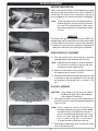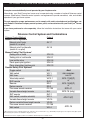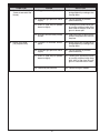
1
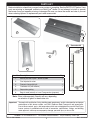
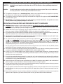
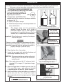
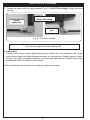
Robert H. Peterson Co.
RHP
Owner’s
Manual
®
GLOWING EMBER
GLASS BURNER
DESIGN CERTIFIED
to
Z21.84b-2004
G45 - GL - 18
G45 - GL - 24
G45 - GL - 30
TRIPLE-T BURNER FOR USE WITH GLASS
Important:
WARNING
If the information in this manual is not
followed exactly, a fire or explosion
may result, causing property damage,
personal injury, or loss of life.
Do not store or use gasoline or other flammable
vapors and liquids in the vicinity of this or any
other appliance.
WHAT TO DO IF YOU SMELL GAS:
•
Open a window.
•
Do not try to light any appliance.
•
Do not touch any electrical switch; do not use
any phone in your building.
•
Immediately call your gas supplier from a
neighbor’s phone. Follow the gas supplier’s
instructions.
•
If you cannot reach your gas supplier, call the
fire department.
-
Installation and service must be performed by
a qualified installer, service agency, or the gas
supplier.
Read these instructions carefully
before starting installation of your
glass burner.
Your Peterson Real-Fyre® glass burner is to be installed
only in a solid-fuel burning fireplace with a working flue
constructed of noncombustible material. Solid-fuels
shall not be burned in a fireplace where this glass
burner is installed. The installation, including provisions
for combustion, ventilation air and required minimum
permanent vent opening, must conform with the National
Fuel Gas Code ( ANSI Z223.1/NFPA 54) and applicable
local building codes. A damper stop clamp is included to
maintain the minimum permanent vent opening and to
prevent full closure of the damper blade. The chimney
damper MUST be fully opened when operating this
burner. Your glass burner is designed to burn with
yellow flames; thus adequate ventilation is absolutely
necessary.
Important:
To comply with certification, listings, and
building codes, and for safe operation
and proper performance, ONLY Peterson
parts and accessories MUST be used
with this glass burner.
INSTALLER & CONSUMER
These instructions MUST be
retained with this appliance.
ROBERT H. PETERSON CO. • 14724 East Proctor Avenue • City of Industry, CA 91746
REV 2- 0701190836
1
No. L-A2-23206
TABLE OF CONTENTS
PARTS LIST
IMPORTANT INFORMATION
FIREPLACE REQUIREMENTS
PRE-INSTALLATION REQUIREMENTS
PRE-INSTALLATION AND FIREPLACE PREPARATION SAFETY
INSTALLATION
INSTALLATION (Continued)
GLASS PLACEMENT
BURNER PREPARATION
OPERATING INSTRUCTIONS
IMPORTANT OPERATING INFORMATION
LIGHTING INSTRUCTIONS
CLEANING AND MAINTENANCE
MAINTENANCE
CLEANING
SERVICE
FLAME DESCRIPTION
OPTIONAL CONTROLS FOR YOUR REAL-FYRE® BURNER SYSTEM
OPTIONAL PETERSON VALVES & SAFETY PILOT KITS
TROUBLESHOOTING YOUR GLASS BURNER
TROUBLESHOOTING YOUR GLASS BURNER (Continued)
WARRANTY
3
4
4
4
5
7
8
9
9
10
10
10
11
11
11
11
11
12
13
14
15
16
Available Glass Colors:
Tools Recommended
The following tools and supplies may be needed to
assemble, install, and test your Real-Fyre® glass set:
1. Adjustable open-ended wrench 8" - 10"
BL = Black
CL = Clear
Z = Bronze
S = Sapphire
E = Emerald
2. Pipe wrench 8" - 10"
3. Pliers
FOR YOUR SAFETY
4. Teflon tape or pipe compound resistant to propane gas
Note: Use Teflon tape or pipe compound resistant to all
gasses on all male pipe threads. Never use pipe
compound or brass flare fittings.
5. Small Phillips-head screwdriver & flat head screwdriver
6. Leak detector or soapy water solution & brush to test for gas
leaks.
7. Work gloves
Other tools used for plumbing or gas appliance installation
may be necessary.
REV 2- 0701190836
2
Do not store or use gasoline or
other flammable vapors and liquids
in the vicinity of this or any other
appliance.
WARNING
Improper installation, adjustment,
alteration, service, or maintenance
can cause injur y or proper ty
damage. Refer to this manual. For
assistance or additional information,
consult a qualified installer, service
agency, or the gas supplier.
No. L-A2-23206
PARTS LIST
Before installation, check that your gas burner system is complete. See the PARTS LIST below. If any
parts are missing or damaged, contact your Real-Fyre® dealer. Do not attempt to install or operate
the burner if any part appears missing or damaged. Be sure you know the model and size of your set
when ordering options or replacement parts and accessories.
All drawings & photos in this manual are not to scale.
1
5
2
4
Connector kit
4A
3
4B
6
Item No. Description
Qty.
1.
Burner pan with Triple-T burner system
1
2.
Fuel injector/air mixer
1
3.
Damper clamp with bolt
1
4.
Connector kit (with elbows)
1
5.
Separation grating
1
6.
Bag of sand (natural) or Lava-Fyre granules (propane)
1
4C
Note: Glass sold separately. Quantity will vary, depending
on selection of glass for decorative use.
Important: To comply with certification, listing, building code acceptances, and for safe operation and proper
performance of this burner system, use ONLY Peterson Real-Fyre® parts and accessories.
Use of other controls, parts, and accessories which are not designed for use with Real-Fyre®
burner systems is prohibited and will void all warranties, certifications, listings, and building
code approvals, and may cause property damage, personal injury, or loss of life.
ROBERT H. PETERSON CO. • 14724 East Proctor Avenue • City of Industry, CA 91746
REV 2- 0701190836
3
No. L-A2-23206
IMPORTANT INFORMATION
Important: Read this manual carefully before starting installation of the glass burner.
Your fireplace must meet venting and construction requirements for the installation of this Real-Fyre® glass
burner (see FIREPLACE REQUIREMENTS section below).
The burner system must be properly sized for your fireplace. Improper sizing may negatively impact the proper drafting
of the fireplace. Additionally, too much glass will adversely affect the burn and hamper the proper operation of the control
system. Too little glass will diminish the beauty of the hearth setting.
Fig. 4-1 below shows the critical dimensions of your firebox. The table below shows glass set dimensions.
FIREPLACE REQUIREMENTS
This Real-Fyre® glass burner is to be installed only in a fully
vented, noncombustible fireplace with an open damper. The
chimney must be free of any obstructions. The fireplace must
be designed and approved to burn wood. The Real-Fyre®
glass set is designed to burn with yellow, smoky flames.
For this reason, it must be adequately vented. The fireplace
flue must be at least 8" at its smallest dimension. If it is
smaller, do not use this Real-Fyre® glass set.
Fig. 4-1
Fireplace Dimensions
Rear width
The fireplace must have a gas supply line that has been
installed by a qualified technician in accordance with all local
codes. The gas supply line must be ½" minimum interior
diameter. If the gas line to the fireplace is longer than 20', a
larger diameter line may be necessary.
Height
Depth
Front
width opening
Required gas pressure: The minimum inlet gas supply
pressure for the purpose of input adjustment is 7" of water
column (w.c.) for natural gas and 11" w.c. for propane gas.
Note: It is recommended that complete firebox dimensions (front width,
back wall, and height) be obtained to ensure proper sizing.
The maximum inlet gas supply pressure is 10.5" w.c. for
natural gas and 13" w.c. for propane gas.
Min. Fireplace Dimensions
Model
no.
Width
*
BTU
Depth Height
Front* Rear†
Natural Propane
G45-GL-18
23"
12"
17"
20"
75M
50M
G45-GL-24
27"
12"
17"
20"
90M
65M
G45-GL-30
33"
12"
17"
20"
90M
65M
Valve
Add to width†
Manual
4"
Series 01
4"
† To center
burner pan in
Series 11
4"
fireplace, double
Series 15
4"
this dimension.
Series 16
4"
Series 20/21
4"
Series 26
4"
† Rear width is at corresponding depth.
Minimum Free Opening Area of Chimney Damper for Venting (sq. in.)
For Factory Built Fireplaces
Burner Sizes
For Masonry Built Fireplaces
Burner Sizes
Chimney
Height
Natural
Propane
Natural
Propane
Natural
Propane
Natural
Propane
15' (min.)
20'
30'
47
42
38
31
28
25
56
50
55
40
37
33
51
46
42
35
32
29
60
54
59
44
41
37
18"
24"/30"
18"
24"/30"
PRE-INSTALLATION REQUIREMENTS
A. Ensure the gas supply to the fireplace is turned off.
PRIOR TO INSTALLING THE SET, the gas supply
line must be tested. Follow the guide lines set by
NFPA 54 or local code requirements.
B. Clean the floor of the fireplace of any dirt or ashes.
C. Chimney must be cleaned and inspected.
Never use propane gas in a set manufactured for natural gas.
REV 2- 0701190836
4
No. L-A2-23206
PRE-INSTALLATION AND FIREPLACE PREPARATION SAFETY
CAUTION: Installation and repair must be done by an NFI Certified or other qualified professional
installer.
Installer:
Carefully read these instructions before installing this gas burner system. Be sure you understand
all safety precautions and warnings contained in this manual.
A. This appliance is designed as an attended appliance. Adults must be present when this gas appliance is operating.
Do not leave this unit burning when unattended or while anyone is sleeping.
B. This appliance is only for use with the type of gas indicated on the rating plate. This appliance is NOT CONVERTIBLE
for use with other gases.
C. BE CAREFUL: If not installed, serviced, and used correctly, per these instructions, this product can cause
serious personal injury, property damage, or loss of life.
PRE-INSTALLATION AND FIREPLACE PREPARATION SAFETY GUIDELINES
D. WARNING: Before installing in a solid- fuel burning fireplace, the chimney flue, damper, and firebox must be thoroughly
CLEANED of soot, creosote, ashes, and loose paint, and must be inspected by a qualified chimney cleaner. Some
older fireplaces may need repair prior to installing this appliance.
E. CHECK GAS TYPE (natural or propane): The gas supply must be the same as stated on your burner system rating
plate. If gas supply is different, DO NOT INSTALL. Contact your dealer for immediate assistance.
F. Any outside air ducts and/or ash dumps located on the floor or walls of the fireplace must be permanently sealed shut
before the installation. Use a heat-resistant sealant. Do not seal the chimney flue damper.
G. INSUFFICIENT GAS PRESSURE WILL KEEP THE PILOT FROM OPERATING PROPERLY. DO NOT USE IF GAS
PRESSURE IS LOWER THAN THE MINIMUM REQUIREMENT.
7" water column (w.c.) on natural gas
H. The minimum inlet gas supply pressure for purposes of input adjustment is 5"
and 11" w.c. on propane gas. Insufficient gas pressure will affect proper operation of the pilot. Do not install this gas
appliance if minimum pressure is not available. The maximum inlet gas supply pressure is 10.5" w.c. on natural gas
and 13" w.c. on propane gas. The propane source must be regulated. (Do not connect this appliance directly to an
unregulated propane gas tank - this can cause an explosion.)
I.
The gas piping system must be sized to provide minimum inlet pressure at the maximum flow rate (BTU/hr). Undue
pressure loss will occur if the pipe is too small, or the run is too long.
J. The minimum clearance from the fireplace opening to combustible materials on side walls and ceiling must be maintained
as outlined in MINIMUM CLEARANCE TO COMBUSTIBLES - WALLS AND CEILING.
K. At least 10"-12" of noncombustible or heat resistant material is required above the fireplace. A fireplace hood will
be required to act as a heat deflector in protecting combustible fireplace surrounds (facing and/or mantel) if certain
minimum clearances cannot be met.
L. Be certain that combustible flooring material (i.e.: carpet, tile, etc.) is not too close to this gas appliance. If this appliance
is at floor level or less than 6" above the floor, there must be at least 12" of noncombustible material between the base
of the fireplace and any combustible flooring.
M. Input ratings shown in BTU per hour are for elevations up to 2,000 ft. For elevations above 2,000 ft., refer to the National
Fuel Gas Code or contact the Robert H. Peterson Company before installing this product.
N. This gas appliance and its main gas valve must be disconnected from the gas supply piping system during any pressure
testing of that system at test pressures in excess of 1/2 psig.
O. This gas appliance must be isolated from the gas supply piping system by closing the equipment shut-off valve connected
to the gas supply line during any pressure testing of the gas supply piping system at test pressures equal to or less
than 1/2 psig.
P. Do not use this appliance if any part has been underwater. Immediately call a qualified service technician to inspect the
appliance and to replace any part of the control system and any gas control that has been underwater.
5
This page intentionally left blank.
6
INSTALLATION
This glass burner must be installed by an NFI Certified or other qualified installer. The installation,
including provisions for combustion and ventilation air, must conform with local codes, or in the absence of
local codes, with the latest edition of the National Fuel Gas Code (ANSI Z223.1/NFPA 54).
TO INSTALL YOUR GLASS BURNER, THE
FOLLOWING STEPS MUST BE FOLLOWED.
1. Locate the gas supply line valve The
gas supply valve must be OFF before
OFF
beginning the installation.
2. A damper clamp (see PARTS LIST) is
supplied and must be installed on the damper assembly
as shown in Fig. 7-1.
a. Open your fireplace damper.
b. Attach the damper clamp on the damper blade and
secure with the bolt.
Note:
The damper clamp must be permanently
installed. Should the clamp not fit, install a
permanent damper stop or other means of
preventing full or accidental closure. (Such as
a screw, bolt, or drilled holes in the damper.)
Open
Closed
Fig. 7-1 Damper clamp in place
Use second
wrench to stop
pipe from turning
Important: When the burner is operating, the damper
must be fully open.
WARNING
Failure to position the parts in accordance with these
instructions and diagrams, or failure to use only parts
specifically approved with this appliance can result in
property damage or personal injury.
Use wrench to
remove stub cap
Fig. 7-2 Removing the stub cap
3. Clean fireplace floor of any ashes.
4. Locate the gas supply stub inside the fireplace and
remove cap if attached (see Fig. 7-2).
CAUTION: When removing the cap make sure the stub
does not turn. It will loosen the connection
inside the wall.
Note: Gas supply pipe must be ½" minimum inside
diameter (I.D.) or larger (¾" if gas line is longer
than 20').
5. Attach the large elbow to fireplace gas stub (see Fig.
7-3), using Teflon tape or pipe compound resistant
to propane gasses on the stub. Tighten securely.
6. Attach small elbow to the fuel injector or air mixer on
burner pan (see Fig. 7-4), using Teflon tape or
pipe compound resistant to propane gasses. Tighten
securely.
DO NOT REMOVE THE
FUEL INJECTOR/AIR MIXER
7
Attach large elbow to stub
Fig. 7-3 Attaching the elbow
Fuel injector or air
mixer
Attach small adapter to fuel injector
on burner pan
Fig. 7-4 Adapter on pan
INSTALLATION (Continued)
7. Connect the elbows with the tubing supplied (Fig. 8-1). DO NOT kink tubing. Tighten both ends
securely.
On gas
supply stub
Connect both
elbows with tubing
On burner
pan
Fig. 8-1 Connector installed
Position the burner pan in the center of the fireplace.
Do not push up against the rear fireplace wall.
8. Leak testing
Carefully turn on the gas supply, ignite the burner pan, and leak test at all connections with a soapy
water solution (equal parts liquid detergent and water) at all connections. If bubbles appear, a leak is
present. Turn off gas and tighten connection, turn on gas and repeat leak test. Repeat until no leaks
are detected. Never use a flame to test for leaks.
When satisfied there are no leaks, turn off the gas supply and proceed.
8
GLASS PLACEMENT
BURNER PREPARATION
Burner pan
After hooking up the burner to the fireplace gas supply
and placing the heat shield on the valve assembly (if
purchased), the media (sand, vermiculite, and glass)
must be added for the burner to function as designed.
Note: These instructions show sand being used as a
base for the glass, but only natural gas burners
use sand. For propane burners, follow these
instructions using Lava-Fyre granules in place
of sand.
Fig. 9-1
WARNING
The burner and pilot (if equipped) must be OFF (fully
extinguished) and all valve covers must be in place before
pouring media onto the burner. It may also be necessary
to temporarily cover the pilot assembly (if equipped) to
keep glass and sand out of it during this procedure.
Fig. 9-2
SAND/GRANULE PLACEMENT
1. Pour the entire bag of sand (natural) or granules
(propane) directly onto the burner pan (Fig. 9-2).
Separation
grating
Note: Keep the media in the pan as much as possible
(it is natural for a little bit to spill out the front
of the pan onto the fireplace floor).
2. Smooth out the media so that it conforms roughly to
the wedge shape of the pan (Fig. 9-2).
3. Place the perforated metal support grid over the sand
or granules so that the angled part hooks over the
top and back of the burner pan, as shown in Fig.
9-3.
Fig. 9-3
GLASS PLACEMENT
CAUTION: Glass pieces may be sharp. Be careful
handling the glass. Use hand protection,
such as gloves, if necessary.
1. Pour the glass directly on top of the support grid so
that the burner pan is covered completely and evenly
(Figs. 9-3, 9-4).
Fig. 9-4
Note: At this stage the burner will function as
designed, however, more glass may be added
around the burner for decorative purposes. If
glass is desired behind the burner pan it may
be left at a lower level than the back of the
pan, as shown in Fig. 9-5, or raised up to
or above the level in the back of the pan.
2. Add additional decorative glass around the burner
pan as desired (Fig. 9-5).
Fig. 9-5
9
OPERATING INSTRUCTIONS
IMPORTANT OPERATING INFORMATION
WHEN THE BURNER IS BURNING, YOUR FIREPLACE DAMPER MUST BE FULLY OPEN.
A fireplace screen must be in place when the glass is burning. Unless other provisions for
combustion air are provided, the screen shall have an opening(s) for introduction of combustion
air.
WHEN A GLASS FIREPLACE ENCLOSURE (DOOR) IS USED, OPERATE THE GLASS BURNER
WITH THE GLASS DOORS OPEN.
Before operating your glass set:
1. Be sure your fireplace is free from flammable liquids or combustible materials.
2. Be sure your damper is open.
3. Smell all around the glass burner for the odor of escaping gas. IF YOU SMELL GAS, FOLLOW THE
INSTRUCTIONS ON PAGE 1.
LIGHTING INSTRUCTIONS
If your glass burner is operated by the fireplace valve:
1. Lay a lighted long-stem match on the surface of the glass near the gas inlet (do not hold the match in
your hand) or use a lighted long-necked butane lighter
(Fig. 10-1).
2. Slowly turn the fireplace to the ON position. Your glass
set should light.
3. If the glass does not light before the match goes out,
immediately turn off the gas to the unit.
4. Wait approximately five (5) minutes to clear out any gas,
and repeat steps 1-3 (above).
5. If your glass fails to light again, turn off the gas to the unit
and contact your dealer or gas supplier.
Fig. 10-1
Apply match-then turn on gas
6. To extinguish your glass burner, make sure the valve
is turned fully OFF to avoid any gas leakage.
If your glass burner is operated by a Peterson manual safety pilot system
(SPK Series) or a Peterson remote safety pilot system (APK Series):
1. Carefully follow the LIGHTING INSTRUCTIONS supplied with your Peterson pilot system for the
steps to ignite the burner.
10
CLEANING AND MAINTENANCE
MAINTENANCE
SERVICE
Once installed and operating properly, your RealFyre® glass burner will require regular maintenance.
You should inspect your glass burner and controls
(where installed) for the following:
While some minor service conditions should
be handled by the owner of the glass burner, a
qualified, professional service technician should
be called to maintain and service your glass
burner and any installed control systems. In
addition, a periodic examination and cleaning
of the solid-fuel burning fireplace venting system
should be conducted by a qualified, professional
service technician. The TROUBLESHOOTING
section of these instructions serves as a guide
for ensuring optimum performance of your glass
burner.
1. Moisture may cause the glass in your burner
pan to settle. To improve the burn, follow
these tips:
a. Settling of glass - Using a screwdriver or
flat blade knife, carefully stir the glass,
loosening the material. Clear up any
spills.
2. Debris around the control (where used) Inspect control and pilot to be sure they are
free of dirt or debris.
To protect your investment in your Real-Fyre®
gas fireplace burner system and keep it operating
safely for years to come, maintain, clean, and
inspect it regularly. We recommend following
these instructions at the beginning of each
fireplace season and as needed throughout the
year, depending on your usage pattern and the
environmental conditions in your home. More
frequent cleaning and maintenance may be
necessary when burning propane gas than with
natural gas.
3. Insects and burner blockage - Check the
burner ports and air shutter, if present, to
make sure they are free from debris. Blocked
burner ports and orifices may result in a fire
at the air shutter.
CLEANING
The pilot assembly must be kept clean and clear
of debris at all times for the fireplace burner
system to be safely and effectively operated.
Dust, carpet fibers, paper, spider webs, pet hair,
etc. in fireplace or on the burner assembly can
affect operation of burner and pilot assembly.
Vacuum or use compressed air from a can or
compressor to clean out pilot assembly area, air
shutter holes, burner orifices, and pilot air intake
openings. Blockage in this area will affect the
operation of pilot assembly.
• Replace all batteries for remote transmitters
and receivers if installed.
• Check and re-adjust the burner air shutter.
• Clean and test the ignitor and pilot.
• Remove and clean artificial logs and/or
glass.
FLAME DESCRIPTION
Observe the flames. The flames should be blue
at the base and a combination of blue/yellow at
the body and tips. The flames should be 16" to
18" tall. (See Figure 11-1).
Figure 11-1
11
OPTIONAL CONTROLS FOR YOUR REAL-FYRE® BURNER SYSTEM
This unit may come without a valve installed.
It may be connected directly to and operated by your fireplace valve.
Alternatively, your Real-Fyre® glass burner may be operated using a number of optional Peterson control
systems (listed below). Peterson control systems are engineered to provide convenient, safe, and reliable
operation of your gas burner system.
For safe operation, proper performance, and to comply with safety standards and certifications, use
only Robert H. Peterson Company control systems, parts, and accessories with your Real-Fyre® burner
system.
If you have purchased a valve separately, follow the installation instructions that come with your control
system.
Peterson Control System and Combinations
Primary Control Method
Manual On/Off Systems
Manual on/off knob
(match lit, no pilot)
Manual on/off rod handle
(match lit, no pilot)
Manual Safety Pilot Systems*
Safety pilot w/ knob
Safety pilot w/ rod handle
Low profile valve
Piezo spark pilot ignition
Piezo intermittent ignition pilot
Remote Safety Pilot Systems*
Toggle switch
Wall switch
Wall timer
Wood chip switch
RUS remote
Remote
Deluxe remote
Pine cone remote receiver
Variable flame height remote
RVF remote
Wall switch (variable w/switch)
Variable flame height remote
Deluxe variable flame height remote
Pine cone remote receiver
Wall switch
Order #
AV-17
AV-18
SPK-20
SPK-21
SPK-26
SPK-32
SPK-33
N/A
WS-1
WS-2
WCS-1
RUS-1
RR-1
RR-2
PC-105
N/A
RVF-1
WS-3
VR-1A
VR-2A
PC-106
WS-4
And
also requires
one of:
APK-11(M)(P)
or
APK-10(M)(P)
or
EPK-01
APK-15 (only)
APK-15(P)
APK-16
*When systems are to be used with propane gas, add a "P" to the control model no. (e.g., APK11MP). Propane glass sets require a safety pilot system.
Not all safety pilot systems are available for all glass set sizes.
**"M" stands for remote capable systems for installations that already have a suitable remote.
12
OPTIONAL PETERSON VALVES & SAFETY PILOT KITS
Note: For all valves and safety pilot kits shown on this page, carefully follow the instructions supplied with
your safety pilot kit for steps to assemble and install it on the burner pan and test for leaks.
SPK-20
*Available from your
local Real-Fyre® dealer
APK-11
Fuel injector
Main
burner
pipe
Aluminum
tubing
Burner
pan
Fuel injector
Main burner
pipe
Burner
pan
Hearth
elbow
Gas
supply
line
APK-11
remote
ready Adapter
valve
Front burner
Fireplace floor
Fireplace floor
Aluminum
tubing
Fig. 13-4
SPK-26
APK-15
Fuel injector
Aluminum
tubing
SPK-26
Valve
APK-15
Valve
APK-15
remote
safety
valve
Fig.
ON
0FF
Fireplace floor
Gas
supply
line
PILOT
L
Adapter
Front burner
SPK-26 Hearth
safety elbow
valve
Fireplace floor
Burner
pan
Main burner
pipe
Aluminum
tubing
Adapter
Front
burner
Fuel injector
Hearth
elbow
Burner
pan
Main burner
pipe
Fig. 13-1
Gas
supply
line
Note: Heat shield is not
shown, but must
be in place when
operating your
glass burner.
SPK-20
Note: Heat shield is not
shown, but must
be in place when
operating your
glass burner.
APK-11
Valve
SPK
valve
Front burner
Fig. 13-5
APK-10
Hearth
elbow
Aluminum tubing
Fuel injector
Main
burner
pipe
Note: Heat shield is not
shown, but must
be in place when
operating your
glass burner.
13-2
Hearth
elbow
Gas
supply
line
Burner
pan
Adapter
APK-10
remote
safety
valve
Front burner
Fireplace floor
APK-16
Main
burner
pipe
Burner
pan
Front burner
Fireplace floor
APK-16
APK-10
Valve
Fuel injector
Aluminum
tubing
Adapter
APK-16
remote
safety
valve
Fig. 13-3
Gas
supply
line
Fig. 13-6
AV-17
AV-18
Note: Heat shield is not
shown, but must
be in place when
operating your
glass burner.
Fuel injector
Main burner
pipe
Burner
pan
Flared adapter
Aluminum
tubing
Hearth
elbow
Note: Heat shield is not
shown, but must
be in place when
operating your
glass burner.
Front
burner
ON/OFF
valve
Fireplace floor
Fig. 13-7
13
Gas
supply
line
Hearth
elbow
TROUBLESHOOTING YOUR GLASS BURNER
SYMPTOM
1. Smoking and/or sooting
CAUSE
A. Poor draft or down draft
A. Check for chimney blockage.
Be sure chimney is at least
3' taller than anything within
10' of it in all directions. If not,
consult a chimney sweep.
Chimney cap or fan may help.
Under severe conditions, you
may need to open a window
near the fireplace about 1" to
2" when burning the glass.
B. Improper burner for gas used
B. Use only a natural gas set
with natural gas or use only a
propane gas set with propane
gas.
C. Damper closed
C. Open damper fully when
operating glass burner.
D. Burner is positioned too close to
the front of the firebox
D. Move set so that the back of
the grate touches the center
of the firebox.
E. Improper glass placement or
amount
E. See PLACEMENT OF GLASS
section.
F. Flue is less than 8" in diameter
F. R e m ove t h e bu r n e r a n d
glass. Inadequate fireplace
ventilation.
G. Air mixer on propane set is
closed
G. Open air mixer completely.
A. Incorrect glass, vermiculite, or
sand for type of gas used
A. Consult your dealer for proper
set.
B. Insufficient gas supply
B. Other gas appliances may
be competing for gas supply.
Consult installer or plumber.
Orifice size is based upon 7"
w.c. pressure for natural gas
and 11" w.c. pressure propane
gas. Plumbing must supply
adequate pressure.
C. Blockage or kink in connector
kit, plumbing or burner orifice
C. Clean out blockage. If connector
kit is kinked, replace it.
D. Valve not fully open
D. Open valve fully.
( I M M E D I AT E LY
STOP USING. Call
your gas supplier
or another qualified
professional installer
or service agency.)
2. Low flame
SOLUTION
14
TROUBLESHOOTING YOUR GLASS BURNER (Continued)
SYMPTOM
3. Uneven flame distribution
(Lower at one end of the
burner)
4. Flame at air mixer
(For propane units)
CAUSE
SOLUTION
A. Clogged or blocked port holes
A. Burner ports can be cleared of
foreign objects by running a wire
through them.
B. Insufficient gas pressure and/or
supply
B. Consult installer or plumber
(see solution 2B).
C. Glass or sand may be packed
down too tightly
C. Loosen glass around burner pipe
by running a kitchen knife along
both sides of the pipe. Even out
glass in burner pan.
D. Auxiliary shut-off valve partially
closed
D. Open valve fully. Usually, you will
find this along the wall 3' from the
fireplace.
A. Clogged or blocked burner
ports
A. Burner ports can be cleared of
foreign objects by running a wire
through them.
B. Insufficient gas pressure and/or
supply
B. Consult installer or plumber
(see solution 2b).
C. Glass or sand may be packed
down too tightly
C. Loosen glass around the burner
by running a kitchen knife along
both sides of the pipe. Be sure
glass is used with an air mixer.
D. Excessive gas pressure
D. Contact your gas supplier.
15
WARRANTY
PETERSON VENTED DECORATIVE GAS APPLIANCE
LIMITED WARRANTY
All Peterson burner assemblies are WARRANTED for TEN (10) YEARS.
All Peterson glass is WARRANTED for TEN (10) YEARS.
SPK-26 controls are covered by a THREE (3) YEAR “All Parts” Warranty.
All other Peterson valves, pilots, and controls are covered by a ONE (1) YEAR Limited Warranty (excluding batteries).
This warranty applies only to the original purchaser, from the date of purchase, and to Peterson products
purchased for residential purposes.
This warranty does not cover parts becoming defective by misuse, accidental damage, electrical damage, improper handling, and/or
installation or service (burners must be installed as outlined in the enclosed instructions by a qualified, professional installer and
with only Peterson parts, control valves, remotes, and accessories). It does not cover labor or labor-related charges. It specifically
excludes liability for indirect, incidental, or consequential damages. Some states do not allow the exclusion or limitation of incidental
or consequential damages, so the above exclusion or limitation may not apply to you. This warranty gives you specified legal rights
and you may have other rights which may vary from state to state.
For additional information regarding this warranty, or information on how to place a warranty claim, contact your Peterson dealer
or the Robert H. Peterson Company.
ROBERT H. PETERSON CO.
Quality Check
Date:___________
Orifice # (Main):__________
Orifice # (Other):__________
Leak Test:
___________
Burn Test:
___________
Gas Type:
NAT. / PROPANE
Model #:
___________
Serial #:
___________
Air Shutter: ___________
Inspector: ___________
Robert H. Peterson Co. • 14724 East Proctor Ave. • City of Industry, CA 91746
16