1
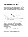
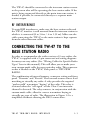
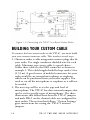
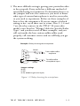
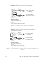
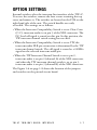
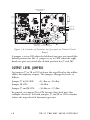
CLEAR-COM ENCORE
TW-47
TWO-WAY RADIO INTERFACE
INSTRUCTION MANUAL
TW-47 Two-Way Radio Interface Instruction Manual
© 2007 Vitec Group Communications Ltd. All rights
reserved.
Part Number 810502Z Rev. 2
Vitec Group Communications, LLC.
850 Marina Village Parkway
Alameda, CA 94501
U.S.A
Vitec Group Communications
7400 Beach Drive
Cambridge Research Park
Cambridgeshire
United Kingdom
CB25 9TP
Vitec Group Communications
Room 1806, Hua Bin Building
No. 8 Yong An Dong Li
Jian Guo Men Wai Ave
Chao Yang District
Beijing, P.R. China 100022
® Clear-Com,CellCom/FreeSpeak and the Clear-Com
Communication Systems logo are registered trademarks of The
Vitec Group plc.
CONTENTS
OPERATION . . . . . . . . . . . . . . . . . . . . . . . . . . 1-1
Introduction . . . . . . . . . . . . . . . . . . . . . . . . . . . . . . . 1-1
Before you Begin . . . . . . . . . . . . . . . . . . . . . . . . . . . . 1-1
Features of the TW-47 System . . . . . . . . . . . . . . . . . . 1-1
Description of the TW-47 . . . . . . . . . . . . . . . . . . . . . 1-2
RF Interference . . . . . . . . . . . . . . . . . . . . . . . . . . . 1-3
Connecting the TW-47 to the Base Station Radio . . . 1-3
Building Your Custom Cable . . . . . . . . . . . . . . . . . . . 1-4
Option Settings . . . . . . . . . . . . . . . . . . . . . . . . . . . . . 1-7
Output Level Jumpers . . . . . . . . . . . . . . . . . . . . . . 1-8
Transmit Key Jumper . . . . . . . . . . . . . . . . . . . . . . . 1-9
Call Signal Frequency Adjust . . . . . . . . . . . . . . . . . 1-9
Check Out and Operation of the TW-47 System . . . 1-9
TW-47 Front Panel Controls and Lights . . . . . . . . . 1-11
Rear Panel of TW-47 . . . . . . . . . . . . . . . . . . . . . . . . 1-12
INSTALLATION. . . . . . . . . . . . . . . . . . . . . . . . . 2-1
Wiring Cables for Specific Radio Types . . . . . . . . . . . 2-1
For Motorola: Radius, GP300, SP-50, and Sport 7x2-1
For Yaesu: FT-411, 811, 911; FT-415, 815; FT-530; FT416, 816; FT-11R, 41R . . . . . . . . . . . . . . . . . . . . . . . 2-1
For Uniden: Model SPH; Motorola: Radius P-50 . 2-2
SPECIFICATIONS. . . . . . . . . . . . . . . . . . . . . . . . 3-1
TW-47 TWO-WAY RADIO INTERFACE
i
TW-47 Technical Specifications. . . . . . . . . . . . . . . . . 3-1
Radio to Party Line . . . . . . . . . . . . . . . . . . . . . . . . 3-1
Party Line to Radio . . . . . . . . . . . . . . . . . . . . . . . . 3-1
LIMITED WARRANTY . . . . . . . . . . . . . . . . . . . . . 4-I
Warranty Period. . . . . . . . . . . . . . . . . . . . . . . . . . . . . .4-i
Technical Support . . . . . . . . . . . . . . . . . . . . . . . . . . . 4-ii
Warranty Repairs and Returns . . . . . . . . . . . . . . . . . .4-iii
Non-Warranty Repairs and Returns . . . . . . . . . . . . . . 4-iv
Extended Warranty . . . . . . . . . . . . . . . . . . . . . . . . . . 4-iv
Liability . . . . . . . . . . . . . . . . . . . . . . . . . . . . . . . . . . . 4-v
ii
TW-47 TWO-WAY RADIO INTERFACE
IMPORTANT SAFETY INSTRUCTIONS
1.
2.
3.
4.
5.
6.
7.
8.
9.
10.
11.
12.
13.
Read these instructions.
Keep these instructions.
Heed all warnings.
Follow all instructions.
Do not use this apparatus near water.
Clean only with dry cloth.
Do not block any ventilation openings. Install in
accordance with the manufacturer’s instructions.
Do not install near any heat sources such as radiators,
heat registers, stoves, or other apparatus (including
amplifiers) that produce heat.
Only use attachments/accessories specified by the
manufacturer.
Use only with the cart, stand, tripod, bracket, or table
specified by the manufacturer, or sold with the
apparatus. When a cart is used, use caution when
moving the cart/apparatus combination to avoid injury
from tip-over.
Unplug this apparatus during lightning storms or when
unused for long periods of time.
Refer all servicing to qualified service personnel.
Servicing is required when the apparatus has been
damaged in any way, such as power-supply cord or plug
is damaged, liquid has been spilled or objects have
fallen into the apparatus, the apparatus has been
exposed to rain or moisture, does not operate normally,
or has been dropped.
WARNING: To reduce the risk of fire or electric
shock, do not expose this product to rain or moisture.
TW-47 TWO-WAY RADIO INTERFACE
i
Please familiarize yourself with the safety symbols in
Figure 1. When you see these symbols on this product,
they warn you of the potential danger of electric shock if
the station is used improperly. They also refer you to
important operating and maintenance instructions in the
manual.
CAUTION
RISK OF ELECTRIC SHOCK
DO NOT OPEN
This symbol alerts you to the presence of uninsulated dangerous
voltage within the product's enclosure that might be of sufficient
magnitude to constitute a risk of electric shock. Do not open
the product's case.
This symbol informs you that important operating and maintenance instructions are included in the literature accompanying
this product.
Figure 1: Safety Symbols
ii
TW-47 TWO-WAY RADIO INTERFACE
EMC AND SAFETY
The TW-47 Two-Way Radio Interface meets all relevant
CE and FCC specifications set out below:
EN55103-1 Electromagnetic compatibility. Product
family standard for audio, video, audio-visual, and
entertainment lighting control apparatus for professional
use. Part 1: Emissions.
EN55103-2 Electromagnetic compatibility. Product
family standard for audio, video, audio-visual, and
entertainment lighting control apparatus for professional
use. Part 2: Immunity.
And thereby compliance with the requirement of
Electromagnetic Compatibility Directive 2004/108/EC
and Low Voltage Directive 2006/95/EC
This device complies with Part 15 of the FCC Rules.
Operation is subject to the following two conditions: (1)
this device may not cause harmful interference, and (2)
this device must accept any interference received,
including interference that may cause undesired
operation.
TW-47 TWO-WAY RADIO INTERFACE
iii
iv
TW-47 TWO-WAY RADIO INTERFACE
1 OPERATION
INTRODUCTION
Congratulations on choosing this Clear-Com product.
Clear-Com was established in 1968 and remains the market
leader in providing intercoms for entertainment,
educational, broadcast and industrial applications. The
ruggedness and high build-quality of Clear-Com products
defines the industry standard. In fact, many of our original
beltpacks and main stations are still in daily use around the
world.
BEFORE YOU BEGIN
To get the most out of your Clear-Com equipment, read this
manual carefully. It will answer many questions you may have
about operating and servicing your equipment. You may also call
Clear-Com’s customer service department at (510) 337-6600 for
answers to any questions that are not covered in this manual.
FEATURES OF THE TW-47 SYSTEM
• Any walkie-talkie with an external microphone input and
earphone output can be connected to the TW-47.
• Clear-Com or TW Channel A or B intercom line operation.
• Powered from the intercom system.
• Base station radio keyed from intercom call signal.
• Visual transmitter keying indicator.
• Audio level indicator.
TW-47 TWO-WAY RADIO INTERFACE
1-1
• Separate transmit and receive level control adjustment.
DESCRIPTION OF THE TW-47
The TW-47 two-way radio interface is a one-channel unit that is
used to connect a two-way radio (commonly known as a walkietalkie) to any channel in a party-line intercom system. When used
with remote radios, the radio connected to the TW-47 acts as if it
were the base station for a wireless remote system. The illustration
in Figure 1-1 shows a typical intercom setup.
Figure 1-1: Typical Intercom Setup Connecting the TW-47 to the
Intercom System
The TW-47 is connected to the intercom system by a 2conductor, shielded cable plugged into its female XLR jack,
labeled “intercom.” The pin-out connectors on the XLR are
configured as follows:
Pin 1 - Shield
Pin 2 - Power/TW Channel A
Pin 3 - Intercom audio/TW Channel B
This is the standard wiring for a Clear-Com intercom system.
With a different setting of the internal switches, the TW-47 will
also accommodate RTS® and compatible systems.
1-2
TW-47 TWO-WAY RADIO INTERFACE
The TW-47 should be connected to the intercom station nearest
to the person who will be operating the base-station radio. If the
unit is being connected directly to the main intercom station, it
should, if possible, be connected directly to a separate main
station output.
RF INTERFERENCE
To avoid RFI interference, make sure the base-station radio and
the TW-47 interface is well removed from the intercom station to
which it is connected (2 to 5 feet / .6 to 1.52 m). Make sure the
cable connecting the TW-47 to the main station is kept separate
from the other intercom cables.
CONNECTING THE TW-47 TO THE
BASE STATION RADIO
In order to accommodate the widest variety of 2-way radios, the
TW-47 is supplied with a 9-pin connector and wiring diagrams
for many two-way radios. (See “Wiring Cables for Specific Radio
Types” later in this manual.) This will allow you to make your
own custom-made cable for your particular radio. This connector
socket is labeled on the TW-47 back panel as TWO-WAY
RADIO.
The combination of internal jumpers, connector wiring and front
panel “Transmit” and “Receive” level controls assures correct level
matching to virtually any radio. A relay provides the required
“push-to-talk” transmitter “keying” of the radio. This relay is
activated when the “call signal” on the Clear-Com intercom
channel is detected. The relay contacts, in conjunction with the
custom-made cable, allow for correct transmitter keying to
virtually any type of radio. The illustration in Figure 1-2 is a
simplified schematic showing the DB-9 connections.
TW-47 TWO-WAY RADIO INTERFACE
1-3
Figure 1-2: Connecting the TW-47 to a Base Station Radio
BUILDING YOUR CUSTOM CABLE
To connect the base-station radio to the TW-47, you must build
your own custom connector cable. This involves several steps.
1. Obtain or make a cable using mini or micro plugs that fit
your radio. Use single conductor shielded wire for each
cable. Miniature type stereo cable is a good choice.
Solder these cables to the DB9 connector as shown in
example 1. This cable length should be kept under 5 feet
(1.52 m). A good source of molded connectors for your
radio would be an external microphone or earphone
which can be purchased from your radio supplier. You
need to cut off the microphone or earphone as it will not
be needed.
2. The next step will be to set the type and level of
microphone. The TW-47 has three internal jumpers that
can be set for specific types of microphones. The three
illustrations that follow show how the TW-47 jumpers
and male DB-9 on the channel cable are configured for
most radios. The section that follows, “Option Settings,”
gives instructions for setting the TW-47’s internal
jumpers.
1-4
TW-47 TWO-WAY RADIO INTERFACE
3. The most difficult setting is getting your particular radio
to key properly. Every radio has a different method of
externally keying its transmitter. To determine how to set
the jumpers and wire the connector, you need to know
what type of external microphone is used in your radio,
or you need to experiment. Below are three examples of
how to key the transmitter. If you are unsure of which
wiring to use, try all three one at a time. Pins 2, 3, 4 and
7 are the relay contacts in the TW-47. If your radio
model is not listed in “Wiring Cables for Specific Radio
Types” and you have tried all three examples, and you
still can’t make the base station walkie-talkie work
properly, call customer service and we will help you get
the system working.
Example 1: Relay shunting the microphone
Shield
1
6
2
Tip
From walkie-talkie
earphone
7
3
8
4
9
Tip
5
To walkie-talkie
microphone input
Shield
Jumper settings
J6 Off
J7 Off
J8 On (Medium gain mic input)
Figure 1-3: Relay shunting the microphone
TW-47 TWO-WAY RADIO INTERFACE
1-5
Example 2: Relay in series with the microphone
Shield
1
6
2
Tip
From walkie-talkie
earphone
7
3
8
4
9
Tip
5
To walkie-talkie
microphone input
Shield
Jumper settings
J6 On (DC path for mic)
J7 Off
J8 On (Medium gain mic input)
Figure 1-4: Relay in series with the microphone
Example 1: Relay across the sleeves of the microphone
and earphone connectors
Shield
1
6
2
Tip
From walkie-talkie
earphone
7
3
8
4
9
Tip
5
To walkie-talkie
microphone input
Shield
Jumper settings
J6 On (DC path for mic)
J7 Off
J8 On (Medium gain mic input)
Figure 1-5: Relay across the sleeves of the mic and earphone connectors
1-6
TW-47 TWO-WAY RADIO INTERFACE
OPTION SETTINGS
Internal switches select the intercom line interface of the TW-47.
To access the switches, remove the four screws retaining the top
cover and remove it. The switches are located on the PCB on the
right hand side of the unit. The switch handles are easily
accessible. The settings are as follows:
• When the Intercom Compatibility Switch is set to Clear-Com
(C-C), intercom audio is on pin 3 of the XLR connector. The
DC level call signal is sensed on this pin. In this position, the
TW intercom channel switch setting has no effect.
• When the Intercom Compatibility Switch is set to TW, the
intercom audio XLR pin connection is determined by the TW
intercom channel switch. The call signal is sensed as a 20 KHz
signal on the selected intercom audio pin.
• When the TW Intercom Channel Switch is set to pin 2,
intercom audio is on pin 2 (channel A) of the XLR connector,
and when the TW intercom channel switch is set to pin 3,
intercom audio is on pin 3 (channel B) of the XLR connector.
The Figure 1-6 on page 1-8 shows the location of the jumpers
and switches on the printed circuit board.
TW-47 TWO-WAY RADIO INTERFACE
1-7
20 KHz Call Signal
Adjustment
Jumper J8
Jumper J7
Jumper J6
Intercom
TW Intercom
Compatibility
Switch (S1) Channel Switch (S2)
TP1
Figure 1-6: Location of Switches and Jumpers on Printed Circuit
Board
A jumper is set to ON when the left hand two pins are joined (the
default position for J6). A jumper is set to OFF when the right
hand two pins are joined (the default position for J7 and J8).
OUTPUT LEVEL JUMPERS
Set jumpers J7 or J8 to ON to lower the signal level to the walkietalkie’s microphone output. The jumpers change the levels, as
follows:
Jumper J7 & J8 OFF:
+11 dbu to –20 dbu
Jumper J8 ON:
–26 dbu
Jumper J7 and J8 ON:
–30 dbu to –57 dbu
In general, set jumper J8 to ON for most low-level mics (for
example, electrets). Set both jumpers J7 and J8 to ON to further
reduce the input level of dynamic-type mics.
1-8
TW-47 TWO-WAY RADIO INTERFACE
TRANSMIT KEY JUMPER
For some walkie-talkies or two-way radios, a dedicated power
path may be needed to activate their transmit function. If so, set
jumper J6 to ON.
CALL SIGNAL FREQUENCY ADJUST
The 20 KHz call signal detector is calibrated at the factory and
should not require further adjustment. If it becomes necessary to
correct the frequency adjustment for any reason, this can be done
by adjusting the internal potentiometer. Refer to Figure 1-6 for
location of the potentiometer.
The adjustment is performed by measuring the frequency at TP1
and adjusting the pot until the frequency is 20 KHz. If the
adjustment must be performed without instruments, connect the
TW-47 to a TW intercom and repeatedly assert a call signal.
Adjust the pot until the red transmit on light on the front panel
accurately tracks the call signal.
CHECK OUT AND OPERATION OF THE
TW-47 SYSTEM
After you have made the appropriate custom cable and connected
the TW-47 to the wired main and wireless base stations, it is now
time to check that everything is working properly.
1. Turn on the base station radio and the remote radio.
Make sure you have fresh or fully charged batteries.
With the external jacks on the base station removed,
make sure the radios are communicating with each
other.
2. Set the base station volume control to approximately half
volume. Have one person listen on the intercom and
have another person talk on the remote walkie-talkie.
You should now be able to communicate from the
remote station walkie-talkie through the base station
TW-47 TWO-WAY RADIO INTERFACE
1-9
into the intercom system. Observe the audio level
indicators on the TW-47. While speaking on the remote
walkie-talkie the green LED should be flashing with
some occasional flashes of the red LED. If this is not the
case adjust the volume control on the base walkie-talkie
to get the desired indication.
3. CHECKING OUT THE BASE STATION
TRANSMITTER: From the main station or remote
station, turn on the talk button for the channel that the
TW-47 is connected to. Press and hold the call button
while speaking. Note the transmit on light on the TW-47
should illuminate and the transmit indicator on the base
station radio (if any) should also illuminate. At this
point you should be communicating from the intercom
system to the remote station walkie-talkie. The transmit
level control on the front panel of the TW-47 adjusts the
volume to the remote station walkie-talkie. Adjust this
level if necessary. Release the call button.
4. Remember that communication to the remote walkietalkie is “push-to-talk.” You must release the call button
to receive communications from the remote walkietalkies.
5. Certain Clear-Com stations can be set up so that the call
signalling can be activated automatically when the “talk”
button is pressed (“call-on-talk”). If this feature is
available on your model of intercom station, set it, but
make sure that the latching feature of the “talk” button is
disabled (“latch disable.”)
1-10
TW-47 TWO-WAY RADIO INTERFACE
TW-47 FRONT PANEL CONTROLS AND
LIGHTS
3 4
2
1
Level Adjust
Receive
Transmit
On
Audio Level
Over Norm
Transmit
TW-47
2-Way Radio
Interface
Figure 1-7: Front View of TW-47
1. RECEIVE LEVEL ADJUST. Use to adjust the receive
level of the base station two-way radio when there is no
external volume control on the base station radio.
CAUTION: The receive level is set at the factory and
should be adjusted only if the remote radio does not
have its own volume adjustment. The default is 12
o’clock (1/2 rotation).
2. TRANSMIT LEVEL ADJUST. Use transmit level adjust
to set the level of the intercom’s audio as heard at the
remote station walkie-talkie.
3. TRANSMIT ON LIGHT. The light illuminates when a
call signal is being sent from the intercom system.
4. AUDIO LEVEL LIGHTS. Red and green lights indicate
the audio level in the intercom system. Use these
indicators to adjust the volume control on the base
station walkie-talkie to match the wired intercom levels.
The red light illuminates when the signal is too high.
Note that proper intercom levels cause the red light to
illuminate about 10 percent of the time.
TW-47 TWO-WAY RADIO INTERFACE
1-11
REAR PANEL OF TW-47
5
6
Intercom
Two-Way Radio
Figure 1-8: Rear View of TW-47
5. INTERCOM LINE CONNECTOR. Use the three-pin
female XLR connector on the TW-47’s back panel to
connect the unit to the intercom channel. As with other
Clear-Com remote stations, power is provided through
the cable.
6. TWO-WAY RADIO CONNECTOR. Use the DB-9F
connector to connect the TW-47 to the base-station
radio.
1-12
TW-47 TWO-WAY RADIO INTERFACE
2 INSTALLATION
WIRING CABLES FOR SPECIFIC RADIO
TYPES
Use the following information to wire cables and set jumpers for
specific radios.
FOR MOTOROLA: RADIUS, GP300, SP-50, AND
SPORT 7X
Set jumpers to the following positions: J6, off; J7, on; J8, on.
Use the example in Figure 2-1 on page 2-1.
To get a molded connector, order Motorola Part#HMN 9787DR
headset with swivel boom mic with clamp.
1
6
Red Shield
Black Tip
Earphone
2
7
3
Microphone
8
4
9
5
White Tip
Shield
(Molded
Connector
Shown)
Note: Set J7 and J8 according to transmit gain requirements
Figure 2-1: Motorola Radios
FOR YAESU: FT-411, 811, 911; FT-415, 815; FT530; FT-416, 816; FT-11R, 41R
TW-47 TWO-WAY RADIO INTERFACE
2-1
Set jumpers to the following positions: J6, on; J7. off; J8, on.
To get a molded connector, order YAESU Part# MH-32 A2B
speaker microphone.
Shield
1
6
Earphone
Tip
2
7
3
8
4
Microphone
9
5
Tip
Shield
Note: Set J7 and J8 according to transmit gain requirements.
Figure 2-2: Yaesu Radios
FOR UNIDEN: MODEL SPH; MOTOROLA: RADIUS P50
Set jumpers to the following positions: J6, on; J7, on; J8, on.
Shield
1
6
Tip
Earphone
2
7
3
8
4
9
5
Tip
Microphone
Shield
Note: Set J7 and J8 according to transmit gain requirements.
Figure 2-3: Uniden & Motorola Radios
2-2
TW-47 TWO-WAY RADIO INTERFACE
3 SPECIFICATIONS
TW-47 TECHNICAL SPECIFICATIONS
dBu is an absolute measurement. 0 dBu is referenced to
0.775 volts RMS
RADIO TO PARTY LINE
LINE CHARACTERISTICS
Frequency Response
Max Gain
Distortion
Noise
Max Level Before Clipping
Green LED Threshold
Red LED Threshold
Input Impedance:
200-20KHz ± 3dB
>=-5dBu
<=0.3%
<=-70dBu
>=+17dBu
-22dBu ± 3dB
-16dBu ± 3dB
400Ω ± 100Ω
PARTY LINE TO RADIO
LINE CHARACTERISTICS
Frequency Response
Max Gain J7 ON, J8 ON
Max Gain J7 OFF, J8 ON
Max Gain J7 OFF, J8 OFF
Distortion
Noise
Max Level Before Clipping
TW-47 TWO-WAY RADIO INTERFACE
200-8KHz ± 3dB
-12dBu ± 3dB
+2dBu ± 3dB
+27dBu ± 3dB
<=0.3%
<=-50dBu
>=0dBu
3-1
Power Requirements
Input Voltage Range
Quiescent Current
Current with Audio
Current with Call
20-30VDC
<=40mA
<=50mA
<=60mA
Rear Panel Connectors
Rear panel:
(1) XLR3F
(1) DB-9F
Front Panel Controls and Indicators
Transmit
Audio Level Hi
Audio Level Norm
Receive Level Adjust
Transmit Level Adjust
Dimensions
(1) Red LED
(1) Red LED
(1) Green LED
(1) Control
(1) Control
1.8"H x 3.95"W x
6.4"D
(46 mm x 100 mm x
163 mm)
Weight
1 lb. 4 oz. (0.6 kg)
Notice About Specifications
While Clear-Com makes every attempt to maintain the
accuracy of the information contained in its product
manuals, that information is subject to change without
notice. Performance specifications included in this manual
are design-center specifications and are included for
customer guidance and to facilitate system installation.
Actual operating performance may vary.
3-2
TW-47 TWO-WAY RADIO INTERFACE
LIMITED WARRANTY
Vitec Group Communications (VGC) warrants that at the
time of purchase, the equipment supplied complies with
any specification in the order confirmation when used
under normal conditions, and is free from defects in
workmanship and materials during the warranty period.
During the warranty period VGC, or any service company
authorized by VGC, will in a commercially reasonable time
remedy defects in materials, design, and workmanship free
of charge by repairing, or should VGC in its discretion
deem it necessary, replacing the product in accordance with
this limited warranty. In no event will VGC be responsible
for incidental, consequential, or special loss or damage,
however caused.
Return Material Authorization (RMA) numbers are
required for all returns.
Both warranty and non-warranty repairs are available.
WARRANTY PERIOD
The product may consist of several parts, each covered by a
different warranty period. The warranty periods are:
• Cables, accessories, components, and consumable items
have a limited warranty of 90 days.
• Headsets, handsets, microphones, and spare parts have a
limited warranty of one year.
• UHF wireless IFB products have a limited warranty of
one year.
WARRANTY
i
• UHF wireless intercom systems have a limited warranty
of three years.
• All other Clear-Com and Drake brand systems and
products, including beltpacks, have a limited warranty of
two years.
The warranty starts at the time of the product’s original
purchase. The warranty start date for contracts which
include installation and commissioning will commence
from the earlier of date of the Site Acceptance Test or three
months from purchase.
TECHNICAL SUPPORT
To ensure complete and timely support to its customers,
VGC’s User Support Center is staffed by qualified technical
personnel. Telephone and email technical support is offered
worldwide by the User Support Center.
The User Support Center is available to VGC’s customers
during the full course of their warranty period.
Instructions for reaching VGC’s User Support Centers are
given below.
Telephone for Europe, Middle East and Africa: +49 40
6688 4040 or +44 1223 815000
Telephone for the Americas and Asia: +1 510 337 6600
Email: [email protected]
Once the standard warranty period has expired, the User
Support Center will continue to provide telephone support
if you have purchased an Extended Warranty.
For latest contact information please refer to the Service
and Support section at www.clearcom.com.
ii
WARRANTY
WARRANTY REPAIRS AND RETURNS
Before returning equipment for repair, contact a User
Support Center to obtain a Return Material Authorization
(RMA). VGC representatives will give you instructions and
addresses for returning your equipment. You must ship the
equipment at your expense, and the support center will
return the equipment at VGC’s expense.
For out-of-box failures, use the following contact
information:
Europe, Middle East and Africa
Tel: +44 1223 815000 Email:
[email protected]
North America, Canada, Mexico, Caribbean & US
Military
Tel: +1 510 337 6600 Email:
[email protected]
Asia Pacific & South America
Tel: +1 510 337 6600 Email:
[email protected]
VGC has the right to inspect the equipment and/or
installation or relevant packaging.
For latest contact information please refer to the Service
and Support section at www.clearcom.com.
WARRANTY
iii
NON-WARRANTY REPAIRS AND RETURNS
For items not under warranty, you must obtain an RMA by
contacting the User Support Center. VGC representatives
will give you instructions and addresses for returning your
equipment.
You must pay all charges to have the equipment shipped to
the support center and returned to you, in addition to the
costs of the repair.
EXTENDED WARRANTY
You can purchase an extended warranty at the time of
purchase or at any time during the first two years of
ownership of the product. The purchase of an extended
warranty extends to five years the warranty of any product
offered with a standard two-year warranty. The total
warranty period will not extend beyond five years.
Note: VGC does not offer warranty extensions on UHF
wireless intercom systems, or on any product with a 1-year
or 90-day warranty.
iv
WARRANTY
LIABILITY
THE FOREGOING WARRANTY IS VGC'S SOLE
AND EXCLUSIVE WARRANTY. THE IMPLIED
WARRANTY OF MERCHANTABILITY AND
FITNESS FOR A PARTICULAR PURPOSE AND ANY
OTHER REQUIRED IMPLIED WARRANTY SHALL
EXPIRE AT THE END OF THE WARRANTY
PERIOD. THERE ARE NO OTHER WARRANTIES
(INCLUDING WITHOUT LIMITATION
WARRANTIES FOR CONSUMABLES AND OTHER
SUPPLIES) OF ANY NATURE WHATSOEVER,
WHETHER ARISING IN CONTRACT, TORT,
NEGLIGENCE OF ANY DEGREE, STRICT
LIABILITY OR OTHERWISE, WITH RESPECT TO
THE PRODUCTS OR ANY PART THEREOF
DELIVERED HEREUNDER, OR FOR ANY
DAMAGES AND/OR LOSSES (INCLUDING LOSS OF
USE, REVENUE, AND/OR PROFITS). SOME STATES
DO NOT ALLOW THE EXCLUSION OR
LIMITATION OF INCIDENTAL OR
CONSEQUENTIAL DAMAGES OR THE
LIMITATION ON HOW LONG AN IMPLIED
WARRANTY LASTS, SO THE ABOVE LIMITATIONS
MAY NOT APPLY TO YOU. IN ANY EVENT, TO THE
MAXIMUM EXTENT PERMITTED UNDER
APPLICABLE LAW, VGC'S LIABILITY TO
CUSTOMER HEREUNDER SHALL NOT UNDER
ANY CIRCUMSTANCES EXCEED THE COST OF
REPAIRING OR REPLACING ANY PART(S) FOUND
TO BE DEFECTIVE WITHIN THE WARRANTY
PERIOD AS AFORESAID.
WARRANTY
v
This warranty does not cover any damage to a product
resulting from cause other than part defect and
malfunction. The VGC warranty does not cover any defect,
malfunction, or failure caused beyond the control of VGC,
including unreasonable or negligent operation, abuse,
accident, failure to follow instructions in the manual,
defective or improperly associated equipment, attempts at
modification and repair not approved by VGC, and
shipping damage. Products with their serial numbers
removed or defaced are not covered by this warranty.
This warranty does not include defects arising from
installation (when not performed by VGC), lightning,
power outages and fluctuations, air conditioning failure,
improper integration with non-approved components,
defects or failures of customer furnished components
resulting in damage to VGC provided product.
This limited warranty is not transferable and cannot be
enforced by anyone other than the original consumer
purchaser.
This warranty gives you specific legal rights and you may
have other rights which vary from country to country.
vi
WARRANTY