1
4004 Fire Alarm
Installation/Operation Instructions
574-074
Rev. C
Technical Manuals Online! - http://www.tech-man.com
Technical Manuals Online! - http://www.tech-man.com
Copyright and Trademarks
Copyright © Simplex Time Recorder Co., 1999. All rights reserved.
Printed in the United States of America.
Information in this document is subject to change without notice. No part of this
document may be reproduced or transmitted in any form or by any means,
electronic or mechanical, for any purpose, without the express written consent of
Simplex Time Recorder Company.
Simplex WALK TEST™ system test is protected under U.S. Patent # 4,725,818.
Cautions and Warnings
DO NOT INSTALL ANY SIMPLEX PRODUCT THAT APPEARS
DAMAGED. Upon unpacking your Simplex product, inspect the contents of the
carton for shipping damage. If damage is apparent, immediately file a claim
with the carrier and notify Simplex.
ELECTRICAL HAZARD - Disconnect electrical power when making any
internal adjustments or repairs. Servicing should be performed by qualified
Simplex Representatives.
Technical Manuals Online! - http://www.tech-man.com
Technical Manuals Online! - http://www.tech-man.com
Table of Contents
Chapter 1 4004 System Overview
Overview .........................................................................................1-1
Environmental .................................................................................1-2
Ground ............................................................................................1-2
Power Input .....................................................................................1-2
Battery Standby...............................................................................1-2
4004 System Features ....................................................................1-2
4004 System Diagram.....................................................................1-3
Chapter 2 Requriments and Accessories
Regulatory Requirments..................................................................2-1
Installation Requirements................................................................2-2
Optional Accessories ......................................................................2-2
Chapter 3 Installation
Requirments ...................................................................................3-1
Back Box ........................................................................................3-1
Wiring .............................................................................................3-2
System Modules.............................................................................3-2
Jumper Settings/Service Switches .................................................3-9
Programming Instructions ............................................................3-11
Chapter 4 Operating Instructions
Front Panel Operation .....................................................................4-1
Operator Key Definitions .................................................................4-1
System Initialization (Power-Up) .....................................................4-3
Supervisory Conditions ...................................................................4-4
Walk Test ........................................................................................4-4
System Testing (Fire Drills).............................................................4-4
Emergency Operating Instructions..................................................4-5
Chapter 5 Glossary of Terms
Chapter 6 4004 Battery Selection
Battery Selection .............................................................................6-1
Battery Selection Calculation ..........................................................6-2
III
Technical Manuals Online! - http://www.tech-man.com
Technical Manuals Online! - http://www.tech-man.com
Chapter 1
4004 System Overview
Overview
The 4004 Fire Alarm Control Panel (FACP) is a general alarm, battery-backed,
electrically supervised system capable of operating two Notification Appliance
Circuits (NACs) and monitoring two Initiating Device Circuits (IDCs) with
expansion capability of up to 8-IDCs. The 4004 FACP is capable of
automatically controlling auxiliary equipment such as fire doors and fans during
a fire condition. The 4004 provide audible and visible indications during Fire
Alarm, Supervisory, or Trouble conditions. If any of these conditions occur, the
system sounds the appropriate notification appliance(s) and flashes the
applicable display (the red “FIRE ALARM ZONE” display for fire alarm zone
indication, the yellow “TROUBLE” display for trouble indication, and the
yellow LED for “Supervisory” operation).
•
Acknowledging the alarm immediately silences the panel audible and
causes the display to illuminate steadily.
•
Pressing the “SYSTEM RESET” key resets the system and causes the
seven-segment alarm and trouble displays to indicate a dash (-) for
15-seconds; following the dash, the displays go out on a successful
system reset or indicate an existing Alarm, Supervisory, or Trouble
Condition(s).
The 4004 system has “Re-sound” capability. Following a Supervisory alarm or
trouble acknowledgment, another circuit goes into alarm, supervisory, or trouble;
the applicable display flashes; and the signals again operate. Once in alarm, the
system remains in alarm until the device that initiated the alarm is restored to
normal and the panel is reset.
The FACP constantly checks for electrical troubles (power loss, battery
problems, wiring faults, etc.). If a Trouble occurs, the tone-alert sounds and the
yellow trouble display indicate the type of trouble(s) in the system. Another
selectable 4004 feature is an active status reminder, if there is an acknowledged
alarm, supervisory, or trouble condition in the system, the tone-alert sounds
every eight hours for five seconds.
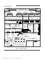
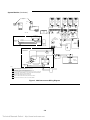
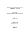
Figure 1 illustrates the physical layout of the cards and the power-limited and
non power-limited wiring areas within the 4004. Printed circuit boards are
joined together in the system by board-to-board connectors or via a wiring
harness connection.
1-1
Technical Manuals Online! - http://www.tech-man.com
Environmental
The 4004 is designed to operate in the following conditions:
•
•
32 - 120° F /0 - 49° C
UL - 85% relative humidity (non-condensing)
ULC - 93% relative humidity (non-condensing)
Ground
The 4004 FACP must be grounded properly. Readings of less than 0.70 VAC
must be measured between ground and neutral. A system ground needs to be
provided for Earth Detection and transient protection devices. This connection
must be made to an approved, dedicated Earth connection per NFPA 70, Article
250, and NFPA 78. To ground the 4004, connect a 12 AWG copper ground
wire from safety ground (electrical distribution panel) to the green grounding
screw on the FACP.
Power Input
The 4004 system is designed for either 120 VAC, 60 Hz or 220/240VAC, 50/60 Hz.
Battery Standby
The battery standby provides for power loss connections. The batteries mount in
the 4004 control panel and provide at least 60 hours of standby operation for a
fully configured system.
Note: 60 hours of standby operation is based on using 10 Ah batteries, without
four-wire detectors or other non-alarm loads attached to the system,
followed by five minutes in alarm. A fully configured system using 6.2
Ah batteries, without four-wire detectors or other non-alarm loads
attached to the system, provides at least 24 hours of standby operation,
followed by five minutes in alarm.
4004 System Features
•
•
•
•
•
•
•
•
•
•
•
•
•
•
•
•
•
•
Expandable from two to a maximum of 8-IDCs
2 Notification Appliance Circuits (NACs)
4 Amps of Power to meet ADA Requirements
Surface or Semi-Flush Installation
Single Piece Chassis
Zone (IDC) Disconnect Switches with Abort Enable Features
Alarm Output Disconnect Switch
One Person Walk Test
Chronological Event Display
Indicator (Lamp) Test Feature
Low and Depleted Battery Detection
Active Status Reminder
Non-volatile Memory
5-IDC Point Type Selections
Six Alarm Silence Inhibit Timer Selections
Four Auto-Silence Timer Selections
Four Coded Signal Selections
Available with Optional
- City Circuits
- Class A (Style D/Style Z) Converters
- Full Function Remote Annunciator Interface
- Simplex 4003 Voice Control Panel and 4009 NAC Extender
1-2
Technical Manuals Online! - http://www.tech-man.com
4004 System Diagram
2
3
1
(-)
(+)
4
SIG 2
(-)
3
SIG 1
(+)
2
1
(-)
(+)
4
SIG 2
(-)
3
SIG 1
(+)
2
1
(-)
(+)
4
SIG 2
(-)
3
(-)
2
1
SIG 1
(+)
4
(+)
(+)
3
SIG 2
(-)
(-)
2
1
SIG 1
(+)
SIG 2
(-)
SIG 1
(+)
CONDUIT ENTRY
POWER LIMITED WIRING
4
CLASS A
CLASS A
CLASS A
CLASS A
CLASS A
CARD 565-585/789
CARD 565-585/789
CARD 565-585/789
CARD 565-585/789
CARD 565-585/789
LP 0V
(-)AUX
(-)RET
(-)
ZN PWR
(-)RET
(-)AUX
(-)AUX
(-)RET
(-)
ZN PWR
(-)RET
(-)AUX
(-)AUX
(-)RET
(-)
ZN PWR
(-)RET
(-)AUX
(-)AUX
(-)RET
(-)
ZN PWR
(-)RET
(-)AUX
5
6
7
8
9
10
11
12
13
14
15
16
12
13
14
15
16
12
13
14
15
16
12
13
14
15
16
SIG 1
SIG 2
TB1
ZONE 6
ZONE 5
DET_PWR.
(+)
4
ZONE 6
ZONE 5
ALARM
(-)
3
ZONE 4
ZONE 3
TBL
(+)
2
ZONE 2
SUPV
AUX(0V)
1
ZONE 1
(-)
AUX(24V)
AUX(-)
ON
ZONE DISCONNECT SWITCHES
ON
Z1 J1
P1
ON
ON
J2
P1
2 PT. IDC 565-575
OR 565-612
Z2
ON
ON
ON
4 POINT CARD 565-589
OR 565-613
9 24V(-)
TROUBLE
SUPERVISORY
ALARM
SILENCED
SYSTEM CARD
WITH POWER SUPPLY
565-573
BATTERY
P1
BLUE
AC
ORN
(+)
(+)
CONDUIT ENTRY
NON-POWER LIMITED
WIRING ONLY
(AC POWER, BATTERY,
CITY CIRCUIT)
1
2
RED (+)
BLACK (-)
3
P4
ON
(-)
AC
RECTIFIER
6 ALM SIL LED
3 ALM SIL SWITCH
SW5
SW4
ALARM OUT
WALKTEST DISCONNECT
ON
ON
ON
2 ACK SWITCH
CITY DISCONNECT
SWITCHES
ON
P5
CITY
FIELD WIRING
(NON-POWER LIMITED)
1
2
SIG 1
3
1 RESET SWITCH
4
FIELD POWER LIMITED WIRING
FOR ANNUNCIATOR INTERFACE CARD
565-579
SIG 2
FUSE
15 AMP
GREY (-)
2
YELLOW 25.5V
1
GREY (-)
TB3
ORANGE (+)
TB2
7 PIEZO
4 TBL LED
YELLOW TROUBLE
LED
SW 3
PGM
8 24V(+)
5 SUPV LED
)-(
ACK
ANNUNCIATOR
INTERFACE
CARD
565-579
CITY
CONNECT
MODULE
565-577
AC POWER
SYSTEM
RESET
)+(
ALARM
SILENCE
)+(
ZONE
)-(
FIRE ALARM
XFORMER
120V
OR
XFORMER
120V
BROWN
(+)
INCOMING
POWER
120V
BLACK
WHITE
10 Ah
BATTERY
MAX
INCOMING
POWER
220V/240V
240V BLACK
220V VIOLET
NEUT WHITE
Figure 1. 4004 System Diagram
1-3
Technical Manuals Online! - http://www.tech-man.com
(-)
(+)
(-)
ON
J2
This page left intentionally blank
Technical Manuals Online! - http://www.tech-man.com
Chapter 2
Requirements and Accessories
Regulatory Requirements
NFPA Standards
The 4004 Fire Alarm System is listed/approved for the following listing
categories:
Listed to UL Standard 864 for the following system types:
•
UL 864 Power-Limited Fire Alarm Control Unit.
•
Local (formerly NFPA 72A).
Requires the sounding of an alarm via the listed
notification appliance(s).
•
Auxiliary (formerly NFPA 72B).
Requires the 4004-9809 City Circuit Module.
•
Remote Station - protected premise (formerly NFPA 72C).
Requires the 4004-9809 City Circuit Module or the
4004-9810 DACT.
•
Proprietary - protected premise (formerly NFPA 72D).
•
Central Station - protected premise (formerly NFPA 71).
Requires the 4004-9810 DACT.
UL 864 Listings for Type of Service:
•
Automatic, Manual, Waterflow, and Sprinkler
Supervisory.
UL 864 Listings for Type of Signaling:
•
Coded, Non-Coded, March-Time, and DACT.
Requires the 4004-9810 DACT.
Factory Mutual Approved
•
Same as UL above.
•
Intrinsically Safe - requires 2081-9036 intrinsically safe
module.
Local/Regional Approvals
•
CSFM
•
MEA
2-1
Technical Manuals Online! - http://www.tech-man.com
Installation Requirements
Optional Accessories
Most NFPA Codes and Standards referenced publications are listed below. You
must be familiar with codes, as well as any applicable local codes and standards,
when installing a fire alarm system.
•
NFPA 72 - National Fire Alarm Code
•
NFPA 11 - Standard for Low-Expansion Foam and Combined
Agent Systems
•
NFPA 11A - Standard for Medium- and High-Expansion Foam
Systems
•
NFPA 12 - Standard on Carbon Dioxide Extinguishing Systems
•
NFPA 12A - Standard on Halon 1301 Fire Extinguishing Systems
•
NFPA 13 - Standard for the Installation of Sprinkler Systems
•
NFPA 15 - Standard for Water Spray Fixed Systems for Fire
Protection
•
NFPA 16 - Standard for the Installation of Deluge Foam-Water
Sprinkler and Foam-Water Spray Systems
•
NFPA 16A - Standard for the Installation of Closed-Head Foam-Water
Sprinkler Systems
•
NFPA 17 - Standard for Dry Chemical Extinguishing Systems
•
NFPA 17A - Standard for Wet Chemical Extinguishing Systems
•
NFPA 25 - Standard for Inspection, Testing, and Maintenance of
Water-Based Fire Protection Systems
•
NFPA 70 - National Electrical Code
•
NFPA 80 - Standard for Fire Doors and Fire Windows
•
NFPA 90A - Standard for the Installation of Air Conditioning and
Ventilation Systems
•
NFPA 90B - Standard for the Installation of Warm Air Heating
and Air Conditioning Systems
•
NFPA 92A - Recommended Practice for Smoke-Control Systems
•
NFPA 92B - Guide for Smoke Management Systems in Malls,
Atria, and, Large Areas
•
NFPA 101 - Life Safety Code
•
NFPA 170 - Standard for Fire Safety Symbols
•
NFPA 231C - Standard for Rack Storage of Materials
•
NFPA 1221 - Standard on the Installation, Maintenance, and Use
of Public Fire Service Communication Systems
4003 Series Voice Control Panel - Provides voice communication capability to
the 4004 Life Safety System.
4009 Series NAC Power Extender - Provides additional power and
Notification Appliance Circuits to the 4004 Life Safety System.
4601 Series Annunciators - Provides remote Annunciation/Control of the 4004
Life Safety System.
2-2
Technical Manuals Online! - http://www.tech-man.com
Chapter 3
Installation
IMPORTANT: Notify appropriate personnel (building occupants,
fire department, or monitoring facility, etc.) of the
installation. Before beginning installation, ensure that
you are thoroughly familiar with these instructions and
all applicable regulatory requirements. (Refer to
Chapter 2 - Requirements and Accessories.)
Requirements
The following tools and equipment are required for 4004 installation:
•
1/4-inch Flat-Tip Screwdriver
•
Volt-Ohmmeter
•
Diagonal Cutting Pliers
•
Wire Strippers
•
End-of-Line Resistors (supplied by Simplex)
•
The 841-992 Field Wiring Diagram
The installer is responsible for safeguarding all 4004 material shipped to the job
site. During system installation, store all 4004 items (including all
documentation) in a clean, dry, and safe place until needed.
Back Box
1.
2.
Remove the back box from the shipping container and lay it on a flat
surface.
Using the information in Figure 2 as a reference, install the back box.
•
For specific internal wiring directions, refer to Figure 2 and the
841-992 Field Wiring Diagram.
Continued on next page
3-1
Technical Manuals Online! - http://www.tech-man.com
Back Box (Continued)
Description
Weight
(See Note 5)
Height
Rough Opening
(See Note 2)
Width
Size
Box
Door
Box
Door
Box
Door
Height
Width
4004
6.5 lb
3.5 lb
16-1/8 in.
17 in.
14-1/2 in.
16-1/8 in.
16-1/8 in.
14-1/2 in.
CAUTION: Enclosure must be level and plumb when installing the back box.
Notes:
1.
The box can be mounted semi-flush with the surface
of the wall (the cabinet protrudes approximately 3/8”).
Dimensions shown are typical for all surface and
semi-flush installations. Use rough opening
dimensions preparing semi-flush installation.
“A” conduit denotes non-power limited wiring only.
“B” conduit denotes power-limited wiring only.
When providing additional conduit entrances to the
box use a suitable knockout punch to provide
separate entrances for power-limited and non-power
limited wiring at the opposite ends of the box. Check
system label on door for power-limited information.
Box weight in pounds (without batteries).
This space must be kept free of wiring for battery
installation.
2.
3.
4.
5.
6.
Figure 2. Back Box Mounting
Wiring
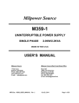
See the interconnect wiring diagram in Figure 3 for basic information on 4004
system wiring. For detailed wiring information, including circuit loading
capacities, distance specifications, and wire size, refer to Figure 1 and the
841-992 Field Wiring Diagram (supplied with the FACP).
System Modules
The Base 4004 System [565-691] consists of:
A System Board with 2-IDCs and 2-NACs - Each IDC on the system board is
capable of supporting up to 30 compatible two-wire detectors. Alarm
verification is supported, with current-limited alarms being verified. Contact
closure results in an immediate alarm. Support for Style D (Class A) IDCs is via
an expansion module. A zone disconnect switch is provided for each IDC.
When restoring a zone to the operative state, activation of notification circuits is
inhibited for 15-seconds. The system sounder and display is not delayed if the
restored zone is in the alarm state. This allows the operator or service technician
to restore the IDC to the disabled state without a general alarm. This operation
is called “Abort Enable” of the IDC. The selectable IDC types allow the user to
define each zone as Fire Monitor, Alarm Verification, Fire/Supervisory, Trouble,
and Style C (See the Programming Instructions section of this chapter).
Continued on next page
3-2
Technical Manuals Online! - http://www.tech-man.com
System Modules (Continued)
The selectable IDC types are as follows:
Fire Monitor - For this point type, an alarm is defined as a direct short or
current-limited condition across the initiating device circuit. An open circuit is a
trouble condition.
Alarm Verification - This point type causes an immediate alarm with a direct
short across the IDC. If current-limited circuit condition exists, the alarm
verification sequence is started. An open circuit is a trouble condition.
Fire/Supervisory - This point type initiates a supervisory service condition at the
fire alarm control panel if a current-limited state is detected. A direct short is an
alarm. An open circuit is a trouble condition. The supervisory status latches until
cleared and reset. If a short circuit or an open circuit occurs before the supervisory
status clears, the supervisory indicators remain on until “SYSTEM RESET” is
pressed and the point is normal.
Trouble - This point type does not cause a fire alarm in the system. A short,
current-limited condition or an open circuit results in trouble. Most trouble
conditions in the system clear automatically when the abnormal condition is
corrected. “SYSTEM RESET” is not required except on Class A circuit
Troubles.
Style C - Style C IDCs indicate a trouble if an open circuit or short circuit
condition is present on the zone loop. A current limited condition causes an
alarm.
Continued on next page
3-3
Technical Manuals Online! - http://www.tech-man.com
System Modules (Continued)
CONNECT TO P5
ON 565-573
565-585
OR
565-789
CLASS A BD
733-885
565-585
OR
565-789
CLASS A BD
2 POINT
733-875
2 POINT
2
OR
565-585
OR
565-789
CLASS A BD
2
J1
565-585
OR
565-789
CLASS A BD
2 POINT
2 POINT
2
J1
565-585
OR
565-789
CLASS A BD
2 POINT
2
2
J1
J1
J1
565-577
CITY BOARD
565-599
DACT BOARD
DETAIL
TELEPHONE
CONNECTORS
A
TB1
MEMBRANE
SWITCH
1
J1
P1
J2
J1
J1
J2
636-746
P1
J1
XFORMER ASSY
636-699
220/240V
J2
P1
3
3
J3
565-589
OR
565-613
IDC BOARD
4 POINT
565-575
OR
565-612
IDC BOARD
2 POINT
636-691
1
SYSTEM BOARD
WITH POWER SUPPLY
BLK 240V
CONTRACTOR
CONNECTION
220/240V
VOL 220V
P4
733-885
(+)
WHT NEUT
565-579
ANNUNCIATOR
(-)
5
P5
4004C AND
4004CF ONLY
SEE DETAIL
B
TB2
BOARD
TB3
BATT
3
NON-POWER LIMITED
AREA ONLY
1
4
2
BATT (+) RED
BATT (-) BLK
2
(+) ORN
(-) GREY
YELLOW 25.5V
1
SEE DETAIL
733-873
RECTIFIER
HARNESS
BLUE
FUSE
15 AMP
208-050
AC (-)
(+)
AC
ORN(+)
733-876
BATTERY HARNESS
GREY(-)
BROWN
XFORMER ASSY
636-698
120V
RECTIFIER
374-034
CONTRACTOR
CONNECTION
120V
BLK 120V
WHT NEUT
NOTES:
1. P.C.BOARDS 565-575,565-589 ARE JOIN TOGETHER TO THE SYSTEM
BOARD,BY BOARD TO BOARD CONNECTORS
4004C AND
4004CF ONLY
2. P.C.BOARD 565-585 OR 565-789 IS ATTACHED THRU THE BOTTOM OF THE
SYSTEM BD,AND 2 POINT,4POINT BOARD BY CONNECTOR J1/J2.
SEE DETAIL
B
3. THE 2 POINT IDC BOARD (565-575) COULD BE IN THE FIRST POSITION LOCATI ON, OR THE 4 POINT
IDC BOARD (565-589) COULD BE INHE
T FIRST POSITION, BOTH BOARDS ARE INTERCHANGEABLE.
4. (565-577) CITY BOARD OR THE (565-599) DACT BOARD MAY BE
CONNECTED TO THE SYSTEM BOARD (565-573) IN THIS AREA.
5. ON 220/240V XFORMER UNUSED WIRE MUST BE COVERED WITH A WIRE NUT.
6. CONNECT INPUT GROUND WIRE TO GROUND STUD USING RING TERMINAL.
Figure 3. 4004 Interconnect Wiring Diagram
3-4
Technical Manuals Online! - http://www.tech-man.com
(+)
(-)
(-)
(+)
A
BATTERY
10 AHR MAX
System Modules (Continued)
The two NACs available with the base 4004 panel are rated at 2-amperes at
24-volts for each circuit. Power-limiting is from the 4004 system power supply.
Additional NACs are added using the 4009 NAC Power Extender. The 4004 is
a general alarm system, meaning that both NACs are energized on any alarm.
Selection of “On Until Silenced” or “On Until Reset” is possible using jumper
switch settings (see the section in this chapter titled “Jumper Settings/Service
Switches). If coding operation is selected, only “On Until Silence” NACs are
coded.
User Interface with AUX circuits for Alarm, Supervisory and Trouble - The
4004 provides for the following auxiliary circuits (negative output):
•
Common Alarm output (on until reset and all fire zones clear). The
Common Alarm output is supervised. [TB1-9]
•
Common Trouble output (latched until all system troubles clear).
[TB1-8]
•
Common Supervisory output (on until reset and all supervisory
zones clear). [TB1-7]
Four-Amp Signal Power Supply with Battery Charger - The system power
supply is part of the system board. A cabinet mounted transformer connects to
the system board. Different transformers are used for 120V and 220/240V
operation. The system power supply provides all necessary system power and
four amperes of signal power. Up to two amperes of auxiliary power is available
from screw terminal connections. AUX power reduces available signal power.
System power is calculated based on three zones in alarm (contact closure being
worst case). If too much alarm current is drawn, the system is protected by
removing loop power and alarms are latched in software. The system power
supply detects earth faults and brown-out/over voltage conditions. The four-amp
power supply battery charger charges 6.2 Ah or 10 Ah batteries needed for
standby operation.
Back Box and Door - The back box for the 4004 mounts between two studs,
16 inches on center. Flush mounting or semi-flush mounting is possible with a
left hinged door.
4004 Expansion Modules (Field Installed):
CAUTION: Power MUST BE REMOVED prior to installing or
replacing expansion modules.
2-IDC Expander Module [565-575] (low current) -The 4004 supports only one
2-IDC expander module in a system. The 2-IDC expander module is used to
expand the system to four or eight zones. Each module terminates for two Style
B initiating circuits. Each circuit supports 2 mA of detector current
(supervisory). Zone disconnect switches are provided on each IDC zone circuit.
An open collector output for each circuit is activated on a short or currentlimited condition. This output can drive and supervise a remote hardwired
annunciator or auxiliary relay load (Air Products) of 150 mA. A 6.8K ohm EOL
is required.
Note: Two 2-IDC Expander modules can not be used to expand a system to six
zones – use one 4-IDC Expander Module.
Continued on next page
3-5
Technical Manuals Online! - http://www.tech-man.com
System Modules (Continued)
2-IDC Expander (Relay Base) [565-612] (high current) - This module is
identical to the 2-IDC expander described above, except that it supports higher
current initiating devices (3 mA) and it supports a single relay base. It also uses
a 3.3 K Ohm EOL resistor that may be desired in retrofit applications.
4-IDC Expander Module [565-589] (low current) - The 4004 supports only
one 4-IDC Expander module in a system. The 4-IDC Expander module is used
to expand the system to six or eight zones. The module includes termination for
four Style B initiating circuits. Zone disconnect switches and all IDC circuitry
are included. Each circuit supports up to 2 mA of detector current (supervisory)
or up to 30 compatible detectors at 50 µA each. An open collector output for
each circuit is activated on a short or current-limited condition. This output can
drive and supervise a remote hardwired annunciator or auxiliary relay load (Air
Products) of 150 mA. A 6.8K ohm EOL is required.
4-IDC Expander (Relay Base) [565-613] (high current) - This module is
identical to the 4-IDC expander (described above), except that it supports higher
current initiating devices (3 mA) and it supports a single relay base. It also uses a
3.3 K Ohm resistor that may be desired in retrofit applications.
Class A IDC/NAC Adapter Module [565-585 or 565-789] - This module
converts two Style B IDCs to two Style D IDCs or two Style Y NACs to two
Style Z NACs. Circuit supervision and alarm status currents are the same as for
the Style B IDC. Circuit rating for a NAC remain two amperes.
City Connect Module [565-577] - This module has two circuits that can be
configured for Municipal Master Box (Local Energy) or Remote Station (Reverse
Polarity) type connections. Wiring to the city connect module is not powerlimited and must be routed (refer to 519-698 wiring label) to preserve the powerlimited integrity of the system. The specific configuration of the city connect
module is selected using jumpers (See the Jumper Settings/Service Switches
section of this chapter). The module has two circuits. The first circuit is used to
signal a fire alarm condition which can be configured for Local Energy or Reverse
Polarity operation. When configured for Reverse Polarity, the circuit
de-energizes on a system trouble, if the second city circuit is configured for
supervisory operation. By de-energizing, the module signals a trouble condition
to the remote station. When the second city circuit is configured for trouble
operation, the alarm circuit does not de-energize on a system trouble. When
system troubles are signaled by de-energizing the alarm circuit, fire alarm
conditions still signal providing city circuit wiring is intact.
City circuit two is configured for either Local Energy or Reverse Polarity
operation. Select whether the circuit activates on a system supervisory or system
trouble condition. The alarm circuit signals system troubles when the second
city circuit is configured for supervisory activation.
Annunciator Interface Module [565-579] - This module is used to drive a
hardwired LED type annunciator. Remote reset, acknowledge, and silence
inputs are provided. Outputs for alarm silenced, system supervisory, and system
trouble are provided. Zone alarm LEDs are driven from the system board or the
IDC expansion modules. All inputs and outputs are supervised on the
annunciator interface, 2-IDC, and 4-IDC modules.
Continued on next page
3-6
Technical Manuals Online! - http://www.tech-man.com
System Modules (Continued)
CCDACT Module [565-626] - The DACT Module uses the same CPU card
connector as the City Connect Module, meaning a system may have either a
DACT Module or a City Connect Module. A DACT trouble output will cause a
4004 system trouble, and is indicated on the seven segment display as a
"City/DACT Trouble" ("C"). Mounting conforms to Power Limited
requirements. The auxiliary Alarm output is on-until-reset. The trouble output
is active until the trouble condition is cleared. The Supervisory output is active
until the condition is cleared for all zones. The AC Fail signal delay is
programmable on the DACT to delay reporting this condition.
Jumper Settings/Service
Switches
The following selections are made jumper settable – see Figure 1 for jumper
locations:
On Until Silence/Reset operation for each NAC.
1. Locate System Board jumpers P2 = NAC 1, P3 = NAC 2.
2. Jump P2-1 to P2-2 and P3-1 to P3-2 for “On Until Reset” operation.
3. Jump P2-2 to P2-3 and P3-2 to P3-3 for “On Until Silenced” operation.
This must be selected for coded operations.
City Circuit configuration for optional City Connect module.
1. To configure City Circuits 1 and 2 as Local Energy or Remote Station,
locate the City Connect module jumpers P2 - P5. Jump P2 - P5 as follows:
Table 1. Jumper Settings
Remote Station
P2-2
to
P2-3
P3-1
to
P3-2
P3-3
to
P3-4
P3-5
to
P3-6
P4-2
to
P4-3
P5-1
to
P5-2
P5-3
to
P5-4
P5-5
to
P5-6
Local Energy
P2-1
to
P2-2
P3-7
to
P3-8
P3-9
to
P3-10
P4-1
to
P4-2
P5-7
to
P5-8
P5-9
to
P5-10
2. Configuration of City Circuit 2 as supervisory, jump P6-1 to P6-2 and P6-3
to P6-4. Configuration of City Circuit 2 as trouble, jump P6-2 to P6-3.
Auxiliary Circuit Supervision:
To supervise AUX Zone 1 or AUX Zone 2 alarm outputs, clip JW1 on System
Board for AUX Zone 1 and clip JW2 for AUX Zone 2.
To supervise AUX Alarm output clip JW3 on System Board.
To supervise AUX Zone Alarm outputs on Zones 3 through 8, remove
JW1-JW4 on 4-IDC expander module and JW1 and JW2 on 2-IDC expander
module.
IDC or NAC configuration for optional Class A converter module - Refer to
Field Wiring Diagram 841-992 supplied with the FACP.
Continued on next page
3-7
Technical Manuals Online! - http://www.tech-man.com
Jumper Settings/Service
Switches (Continued)
The 4004 has the following service switches for servicing and testing the
system (see Figure 1):
Zone Disconnect Switch - “ON” for normal operation and “OFF” to disconnect
zone. To disconnect a 4004 zone from a normal state, slide the Zone Disconnect
Switch for any zone in alarm to the “OFF” position. this transfers the zone(s)
from a normal condition to a zone disconnect trouble condition. Press the
“ACK” key to acknowledge the trouble condition(s).
When restoring a zone to the operative state, activation of notification circuits is
inhibited for 15-seconds. The system sounder and display is not delayed if the
restored zone is in the alarm state. This allows the operator or service technician
to restore the IDC to the disabled state without a general alarm. This operation
is called “Abort Enable” of the IDC.
To disconnect a 4004 zone from an alarm state, toggle the Zone Disconnect
Switch to the “OFF” position, then to the “ON” position, and once again to the
“OFF” position. This transfers the zone(s) from a normal condition to a zone
disconnect trouble condition. Press the “ACK” key to acknowledge the zone
disconnect trouble condition(s). Press “SYSTEM RESET” to reset the system
and clear the alarm outputs. A trouble is reported for any zone(s) in disconnect.
Press the “ACK” key to acknowledge the trouble condition(s).
To re-connect a 4004 zone from the disconnect state, slide the Zone Disconnect
Switch for the desired zone(s) to the “ON” position. Press “SYSTEM RESET”
to clear the zone disconnect trouble condition(s).
City Disconnect Switch - “ON” for normal operation and “OFF” to disconnect.
A system trouble indicates when the city is disconnected. There is a switch for
each city circuit on the city connect module.
Alarm Output Disconnect Switch - This switch is used to disable all system
alarm outputs. This includes NACs, Alarm City Circuit, Auxiliary Alarm
Output, and Zone Alarm Outputs. When the switch is “OFF” the system is in
the normal operation mode. When the switch is “ON” all of the above circuits
are disabled. Trouble indications are indicated for each disabled circuit.
Activation of this switch is ignored when the system is in alarm, you must clear
Alarm and Reset conditions before switching back to the “OFF” position.
Walk Test Switch - “OFF” for normal operation and “ON” places the system in
Walk Test mode. Activation of this switch “ON” allows one person to test the
system. If system is in alarm the activation of the switch is ignored.
Program Switch - “OFF” for normal operation and “ON” places the system in
the program mode. Activation of this switch is ignored if the system is in alarm.
3-8
Technical Manuals Online! - http://www.tech-man.com
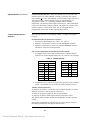
Programming Instructions
No special programming equipment is needed to configure the 4004 system. If
no programming options are selected, the panel operates with the following
default conditions:
•
System configured for 8-IDC, CITY/DACT, Annunciator Interface.
•
All IDCs are FIRE type, no Alarm Verification or Fire/Supervisory
points.
•
NAC 1 is coded Temporal until Silence (no cut out or inhibit).
•
NAC 2 is on steady until Reset.
•
Abnormal condition reminder active.
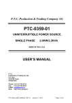
The 4004 panel is programmed for the desired mode of operation by using the
seven-segment displays and the “ACK” and “SYSTEM RESET” keys for
scrolling through programming options and set-ups. A switch (SW3) places the
panel in the program mode. No alarms or troubles are processed when the panel
is in the program mode.
The program switch is ignored if there are alarm conditions in the panel.
Entering the program mode causes trouble indicated by a lowercase “h” on the
yellow “TROUBLE” display. The user interface panel “ACK” key
acknowledges the program mode trouble and silences the tone-alert. The “ACK”
key selects configuration number and the “SYSTEM RESET” key selects the
configuration option. Refer to Figure 4 for complete system programming
configuration options.
1.
Enter program mode by activating switch SW3. Tone-alert sounds until
“ACK” key is pressed. A lowercase “h” is indicated on the yellow
“TROUBLE” display.
2.
Refer to Figure 4 for the following programming operation:
•
To scroll through the available program options press the “ACK” key.
•
To scroll through the available selections for each program option press
the “SYSTEM RESET” key.
•
When desired programming is completed, exit the program mode by
deactivating switch SW3. Program set-up is saved into non-volatile
system memory and the lower case “h” on the yellow “TROUBLE”
display clears. Write down program set-up in the “CURRENT
SETUP” section on the 4004 door panel label.
Continued on next page
3-9
Technical Manuals Online! - http://www.tech-man.com
Programming Instructions
(continued)
TROUBLE
FIRE ALARM
SUPERVISORY
ZONE
ALARM
SILENCED
ACK
ALARM
SILENCE
SCROLL
THRU
OPTIONS
SCROLL
THRU
SETUPS
PROGRAM
= NUMBER
OF ZONES
AC POWER
SYSTEM
RESET
CURRENT
SETUP
SELECTION
= DEFAULT
Number of zones in the system.
= ZONES
= ZONE 1
= ZONE 2
= FIRE MONITOR
= ZONE 3
= ALARM VERIFICATION
= ZONE 4
= FIRE/SUPERVISORY
= ZONE 5
= TROUBLE ONLY
= ZONE 6
= STYLE C
Defines the initiating Device point
type. Select zone by scrolling through
options with the "ACK" key. Select
the desired point type for the selected
zone using the "SYSTEM RESET" key.
= ZONE 7
= ZONE 8
=
CITY
OR
DACT CARD
= NOT INSTALLED
City/Dact module present/not present in the system.
= INSTALLED
= NONE
= 1 MINUTE
=
SIGNAL
SILENCE
INHIBIT
= 2 MINUTE
= 3 MINUTE
= 4 MINUTE
= 5 MINUTE
Defines Notification Appliances operation.
Select the desired operation using the
"SYSTEM RESET" key. Define parameters
for the selected operation using the "ALARM
SILENCE" key.
= NONE
=
ALARM
SILENCE
CUTOUT
= 10 MINUTES
= 20 MINUTES
= 30 MINUTES
= NONE
= TEMPORAL
CODING
= OPTIONS
= MARCH TIME-20 BPM
= MARCH TIME-120 BPM
= SIMPLE CODING
=
=
ANNUN
INTERFACE
CARD
TBL/ALM/
SUPV
REMINDER
= NOT INSTALLED
Annunciator interface present/not present in the system.
= INSTALLED
= NON-ACTIVE
= ACTIVE
Abnormal condition reminder.
Figure 4. 4004 Programming Selections
This page left intentionally blank
3-10
Technical Manuals Online! - http://www.tech-man.com
Chapter 4
Operating Instructions
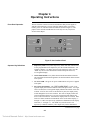
Front Panel Operation
The user interface consists of controls and indicators that provide support to
4004 fire alarm functions. The user interface indicates alarm, supervisory,
trouble, power on, and alarm silenced conditions (shown in Figure 5). The
purpose of the controls and indicators are in the Operator Key Definitions
section of this chapter.
TROUBLE
FIRE ALARM
SUPERVISORY
ZONE
ALARM
SILENCED
ALARM
SILENCE
ACK
SYSTEM
RESET
AC POWER
Figure 5. User Interface Panel
Operator Key Definitions
1.
Supervisory LED - The yellow Supervisory LED, when ON, indicates that
a zone programmed as Fire/Supervisory is in the current-limited state – not
an alarm condition. To display the zone in the supervisory state, press the
“ACK” key and view the zone number with decimal point on the red,
seven-segment display.
2.
Alarm Silenced LED - The yellow alarm-silenced LED indicates that the
On Until Silenced notification appliances are OFF and that an alarm remains
in the system.
3.
AC Power LED - The green AC power LED indicates AC power is applied
to the panel.
4.
Fire Alarm Zone Display - The “FIRE ALARM ZONE” is a red, sevensegment display that is used to indicate alarms and supervisories. If a single
zone is in alarm, the seven-segment display indicates the number of the zone
in alarm. If two or more zones are in alarm at any time, the display slowly
scrolls through the list of zones in alarm. The order of display follows the
order in which the alarms were received. The decimal point indicates the
start or end of an alarm list. Each alarm is displayed for two seconds. IDCs
with a fire alarm condition are illuminated on the red fire alarm display (‘1’
through ‘8’). IDCs in a supervisory condition are illuminated on the display
with a dot (‘1.’ through ‘8.’). The “ACK” key must be used to view
supervisory conditions when the yellow Supervisory LED is illuminated.
Continued on next page
4-1
Technical Manuals Online! - http://www.tech-man.com
Operator Key Definitions
(Continued)
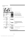
5.
Trouble Display - The “TROUBLE” LED is a yellow, seven-segment that is
used to indicate IDC, NAC, City Circuit, Power Supply, AUX output, and
various system trouble conditions. The IDC troubles are displayed using
numerals 1 through 8, other troubles are displayed alphabetically (See Table
2 for a list of troubles indicated on the yellow “TROUBLE” display). The
scrolling operation is identical as described in the “FIRE ALARM ZONE”
display. If two or more trouble conditions are present, the display slowly
scrolls through the list. If manual scrolling is desired, the “ACK” key scrolls
through trouble indications sequentially after showing all alarms and
supervisory points. Scrolling rotates between “Alarm”, “Supervisory”, and
“Trouble” lists. Inactivity on the “ACK” key for ten seconds starts the
scrolling sequence.
Table 2. Yellow Trouble Indicators
Indicator
1 through 8
1. through 8.
Description
IDC Zones
IDC AUX Output
A
Annunciator Card Trouble
A.
AUX Alarm Output
b
Battery Low
C
City/DACT Trouble
c
Configuration Trouble
d
Depleted/Disconnected Battery
E
NAC 1 Trouble
F
NAC 2 Trouble
H
Walk Test Trouble
h
Program Trouble
P
Power Supply Trouble
P.
Ground Fault Trouble
6.
System Reset Key - The “SYSTEM RESET” key when pressed removes
IDC loop power (two and four-wire) for 5 seconds. If all zones are clear,
signals “On Until Silence” and “On Until Reset” are turned OFF. The
“Alarm Silenced” LED and annunciator alarm outputs are turned OFF.
When “SYSTEM RESET” is in progress, dashes (-) are displayed on the
red (Fire Alarm) and yellow (Trouble) seven-segment displays.
7.
Acknowledge “ACK” Key - The “ACK” key is used to acknowledge alarm,
supervisory, and trouble conditions. Every system status change causes the
tone-alert to sound until the “ACK” key is pressed. Each type of condition
must be acknowledged via the “ACK” key, the tone-alert sounds until all
conditions have been acknowledged. The “ACK” key acknowledges the
type of conditions in the following priority: (1) Alarm, (2) Supervisory, and
(3) Trouble.
Continued on next page
4-2
Technical Manuals Online! - http://www.tech-man.com
Operator Key Definitions
(Continued)
The “ACK” key is also used to perform a lamp test on the system LEDs and
displays. When the “ACK” key is pressed for five seconds, the red and
yellow, seven-segment displays (all segments), System tone-alert and Power
On, Alarm Silenced, and Supervisory LEDs turn ON and remain ON until
the “ACK” key is released.
8.
System Initialization
(Power-Up)
Alarm Silence Key - The “ALARM SILENCE” key de-energizes NACs
configured as “On Until Silence.” The “ALARM SILENCED” LED turns
ON and remains ON until all alarms are cleared.
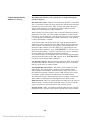
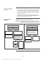
Follow the flow chart below to initialize the 4004 FACP.
IMPORTANT: Notify appropriate personnel (building occupants, fire
department and/or monitoring facility, etc.) of power-up.
NORMAL POWER-UP CONDITIONS
POWER-UP TROUBLE CONDITIONS
A p p ly s y s te m p o w e r to th e 4 0 0 4 p a n e l.
A p p ly s y s te m p o w e r to th e 4 0 0 4 p a n e l.
T h e p a n e l d is p la y s a n d in d ic a to r s a p p e a r .
T h e p a n e l d is p la y s a n d in d ic a to r s D O N O T a p p e a r .
T h e to n e a le r t s o u n d s fo r o n e
s e c o n d a n d th e u s e r in te r f a c e
p a n e l “ A C P O W E R ” L E D is O N .
P r o g r a m th e 4 0 0 4 fo r y o u r d e s ir e d
s y s te m c o n fig u r a tio n ( S e e C h a p t e r
2 – “ P r o g r a m m in g I n s tr u c tio n s ” ) .
T
p
s
o
h e to n e
r e s s in g
y s te m S
n th e re
a le r t s o u n d s c o n tin
th e “ A C K ” k e y in d ic
u p e r v is o r y , T r o u b le
d o r y e llo w d is p la y s
F u s e s m a y h a v e o p e n e d o r a c ir c u it b r e a k e r m a y
h a v e tr ip p e d .
Make sure power is removed from the panel and
appropriate circuit is disconnected from the
panel and when checking the system.
u o u s ly a n d
a te s a
, o r A la r m
.
C h e c k F ie ld W ir in g D ia g r a m 8 4 1 - 9 9 2 .
Make sure that power is removed
from the panel and the appropriate
circuit is disconnected from the
panel when checking the circuit.
If, a fte r c h e c k in g fu s e s a n d /o r
c ir c u its , th e S y s te m a p p e a r s
O K .
R e a p p ly p o w e r to th e
S y s te m .
If, a fte r c h e c k in g
c ir c u its , th e S y s te m
a p p e a rs O K .
R e a p p ly p o w e r t o
th e S y s te m .
If th e s y s te m s t ill
in d ic a te s c o n d itio n s
o n th e r e d o r y e llo w
d is p la y s a fte r fie ld
w ir in g c h e c k s ,
c o n ta c t y o u r lo c a l
S im p le x B r a n c h
O ffic e ( lis te d in th e
Y e llo w P a g e s u n d e r
F ir e A la r m ) .
4-3
Technical Manuals Online! - http://www.tech-man.com
If a fu s e c o n
c ir c u it b r e a k
tr ip , c o n ta c t
S im p le x B r a
in th e Y e llo w
F ir e A la r m ) .
tin
e r
yo
n c
P
u e s to o p e n o r
c o n tin u e s to
u r lo c a l
h O ffic e ( lis te d
a g e s u n d e r
Supervisory Conditions
A Fire/Supervisory point distinguishes between Fire Alarm and Supervisory
conditions on a single circuit. When water is flowing in a sprinkler system, an
Alarm is indicated, but if a sprinkler or water pump valve has been closed, a
“SUPERVISORY” service condition is indicated. This condition is distinctly
different from a trouble or alarm condition. The yellow “SUPERVISORY”
LED flashes and the tone-alert sounds until the condition is acknowledged via
the “ACK” key. After pressing the “ACK” key, the “SUPERVISORY” LED is
ON steady, unless the user is scrolling (Supervisory is second priority). The
supervisory state is only available on points configured as Fire/Supervisory type.
Walk Test
The 4004 is equipped with Walk Test, this feature allows one person to test the
4004 System. Walk Test is activated using the dedicated switch (SW4 on the
System Board). The following conditions apply during Walk Test operation.
System Testing (Fire Drills)
•
Alarm - An alarm from an IDC is indicated with zone code notification
over both NACs. If NACs are connected to strobes, the strobes may
not indicate the zone code.
•
Trouble - A trouble from any IDC, NAC, or an Earth Fault is indicated
by activating NACs for four seconds.
•
Walk Test switch is ignored if there is an alarm in the system.
•
An upper case “H” on the yellow “TROUBLE” display indicates Walk
Test trouble.
•
City Circuit activation is not inhibited during Walk Test, it must be
disconnected via the Disconnect Switches on the card.
•
Display and tone-alert function as they would under normal conditions.
•
Automatic system reset occurs within 30 seconds after Walk Test alarm.
•
Subsequent alarms on the same zone causes another zone code (not a
zero code).
•
A “SYSTEM RESET” is done when exiting from Walk Test. Any
zones still in an alarm condition initiate an alarm after the system reset.
Fire Drills must be conducted periodically to ensure that the building occupants
are familiar with emergency procedures and that all system equipment is
functioning properly and is in good condition. This testing should be done under
the direction of the owner and the local Authority Having Jurisdiction (AHJ).
System testing is initiated when the following considerations have been
determined:
•
How does the owner and AHJ want the drill or test performed?
•
Is the building occupied?
•
Which system features are currently in use?
If a building is not occupied and no city connection or DACT are used, there is
less concern that confusion will result from testing the system. Systems
connected to a city circuit must notify the local AHJ. The AHJ determines if the
city connection should be disabled during the test.
Continued on next page
4-4
Technical Manuals Online! - http://www.tech-man.com
System Testing (Fire Drills)
(Continued)
The optional city module has disconnect switch(s) SW1 (City Circuit 1) and
SW2 (City Circuit 2) that disables the city circuit if desired. If the AHJ wanted
to test the city box, the city circuit disconnect switch(s) would not be enabled. A
system wired with the optional DACT module must have system testing
coordinated with the Central Station operator and the AHJ.
To initiate a test with the 4004, activate an initiating device (pull station, smoke
detector etc.). The test simulates a real alarm condition. This allows the
building occupants to become familiar with the conditions encountered in an
actual fire emergency condition.
Emergency Operating
Instructions
If the 4004 Fire Alarm System has an Alarm, Supervisory, or Trouble condition,
refer to Figure 6 for Emergency Operation procedures.
EMERGENCY OPERATING INSTRUCTIONS
ALARM–SUPERVISORY–TROUBLE CONDITION:
–SYSTEM INDICATOR FLASHING, TONE ON.
TO ACKNOWLEDGE:
–PRESS “ACK” UNTIL TONE ALERT IS SILENCED
–REVIEW FIRE ALARM & TROUBLE INDICATORS
–SUMON APPROPRIATE PERSONNEL TO INVESTIGATE
TO SILENCE ALARM SIGNALS:
–PRESS “ALARM SILENCE”.
TO RESTORE SYSTEM TO NORMAL:
–PRESS “SYSTEM RESET”. SYSTEM RESET WITHIN 15 SEC
A DASH WILL APPEAR IN BOTH FIRE & TROUBLE INDICATORS
WHILE SYSTEM RESET IS IN PROGRESS.
LAMP TEST:
–PRESS “ACK” FOR 5 SEC
Figure 6. Emergency Operating Instructions
4-5
Technical Manuals Online! - http://www.tech-man.com
This page left intentionally blank
Technical Manuals Online! - http://www.tech-man.com
Chapter 5
Glossary of Terms
Glossary of Terms
Alarm - A warning of fire danger.
Alarm Signal - A signal indicating an emergency requiring immediate action,
such as a signal indicative of fire.
Alarm Verification - A feature to reduce unwanted alarms wherein smoke
detectors must report alarm conditions for a minimum period of time. Alarm
Verification also confirms alarm conditions within a given time period, after
being reset to be accepted as a valid alarm initiation signal.
Annunciator - A unit containing two or more indicating lamps, alpha-numeric
displays, or other equivalent means in which each indication provides status
information about a circuit, condition or location.
Authority Having Jurisdiction - The “Authority Having Jurisdiction” is the
organization, office or individual responsible for approving equipment, an
installation, or a procedure.
Class A - A four-wire method of connecting IDC or NAC that guarantees
operation with a single open conductor. See Style D (IDC) and Style Z (NAC).
Class B - A two-wire method of connecting IDC or NAC that causes a trouble
indication with an open circuit. See Style B (IDC) and Style Y (NAC).
Current-Limited IDC State - A “current-limited” state exists when an initiating
device shunts a resistor across the IDC. For the 4004 system, this resistor is
defined as 400-820 ohms.
Digital Alarm Communicator Transmitter (DACT) - A system component at
the protected premises to which initiating devices or groups of devices are
connected. The DACT seizes the connected telephone line, dials a pre-selected
number to connect to a Digital Alarm Communicator Receiver (DACR), and
transmit signals indicating a status change of the initiating device.
Display - The visual representation of output data other than printed copy.
Evacuation - The withdrawal of occupants from a building.
Evacuation Signal - A distinctive signal intended to be recognized by the
occupants as requiring evacuation of the building.
FACP - Fire Alarm Control Panel. A system component that receives input
from automatic and manual fire alarm devices and may supply power to
detection devices and transponders or off-premises transmitters. The control
panel can provide transfer of power to the notification appliances and transfer of
conditions to relays or devices connected to the control panel. The FACP can be
a local fire alarm control panel or a master control panel.
Fire/Supervisory - An IDC point type that is zone selectable. This point type
initiates a “Supervisory Abnormal” condition at the FACP if a current-limited
state is detected.
Heat Detector - A device that detects abnormally high temperature or rate of
temperature rise.
Continued on next page
5-1
Technical Manuals Online! - http://www.tech-man.com
Glossary of Terms (Continued)
Initiating Device - A system component that originates transmission of a change
of state condition, such as a smoke detector, manual fire alarm box, supervisory
switch, etc.
Initiating Device Circuit (IDC) - A circuit to which automatic or manual
initiating devices are connected where the signal received does not identify the
individual device operated.
Labeled - Equipment or materials to which has been attached a label, symbol, or
other identifying mark of an organization acceptable to the “Authority Having
Jurisdiction” and concerned with product evaluation, that maintains periodic
inspection of production labeled equipment of materials and by whose labeling
the manufacturer indicates compliance with appropriate standards or
performance in a specified manner.
Listed - Equipment or materials included in a list published by an organization
acceptable to the “Authority Having Jurisdiction” and concerned with product
evaluation, that maintains periodic inspection of production of listed equipment
or materials and whose listing states either the equipment or material meets
appropriate standards or has been tested and found suitable for use in a specified
manner.
March Time Code - A notification code that consists of a 50% duty cycle pulse
train. The march time rate is specified in beats per minute (BPM). A 20 BPM
March Time Code consists of 20 ON/OFF cycles in one minute.
Municipal Master Box - An indicating device intended to send an alarm
condition to the public fire service communication center.
Normal State (IDC) - The normal state is defined as the end of line resistor in
place with the full range of line resistance and detector load.
Notification Appliance - A fire alarm system component such as a bell, horn,
strobe, etc., that provides an audible or visible output, or both.
Notification Appliance Circuit (NAC) - A circuit or path directly connected to
one or more notification appliances.
Open Circuit State (IDC) - An open circuit is defined as the absence of the
end-of-line resistor, with or without a detector load.
Protected Premises - The physical location protected by a fire alarm system.
Remote Station Circuit - A circuit intended to send alarm, supervisory, and/or
trouble signals to a remote location at which appropriate action is taken.
Short Circuit IDC State - A short circuit exists when an initiating device shunts
a low resistance contact across the IDC. The contact resistance is defined as
0-200 ohms.
Simple Code - A code consisting of a distinct number of pulses used to indicate
which zone (IDC) is in alarm. The number of pulses is the same as the number
assigned to the zone in alarm.
Smoke Detector - A device that detects visible or invisible particles of
combustion.
Continued on next page
5-2
Technical Manuals Online! - http://www.tech-man.com
Glossary of Terms (Continued)
States - The state of an IDC is determined by the physical condition of the
wiring and devices connected to the terminal block. There are four states
associated with an IDC:
•
Short (0-200 ohms).
•
Current-limited state (400-820 ohms), across the initiating device
circuit.
• Normal state (defined as the end-of-line resistor in place with the full
range of line resistance and detector load).
• Open circuit state (defined as the absence of the end-of-line resistor,
with or without a detector load).
Style B - A method of connection for IDC that provides a trouble indication in
the event of an open circuit on the wiring loop (also known as Class B).
Style C/Style E - An IDC point type. A trouble indication is provided if a short
(plus to minus) or open circuit condition exists on the wiring loop. An alarm is
initiated if a “current-limited” state exists. Style C is two-wire, Style E is fourwire.
Style D - A method of connecting initiating devices on IDCs that provide
multiple signal paths so that circuit operation is maintained with a single open
circuit connection. A trouble indication is provided in the event of an open
circuit on the wiring loop (also known as Class A).
Style Y - A method for connecting notification appliances on NACs that provide
a trouble indication in the event of an open circuit on the wiring loop
(also known as Class B).
Style Z - A method of connecting notification appliances on NACs that provide
multiple signal paths so that circuit operation is maintained with a single open
circuit connection. A trouble indication is provided in the event of an open
circuit on the wiring loop (also known as Class A).
Supervisory Signal - A signal indicating the need of action in connection with
the fire suppression system or equipment, or with the maintenance features of
related systems.
Temporal Code - A three coding pulse pattern adopted by NFPA as a standard
evacuation pattern for audible notification. The pattern consists of three,
0.5-second pulses, each pulse separated by 0.5-second silence. Each group of
three pulses is separated by 1.5-seconds of silence.
VSMOKE - A point type that is selectable for an IDC. This point type initiates
an immediate alarm from a contact closure Pull Station or Heat Detector, but
initiates the Alarm Verification sequence (see definition above) for a
current-limited alarm. A point configured as VSMOKE must not have any
devices other than smoke detectors that initiate a current-limited alarm.
Zone - A defined area within the protected premises. A zone may define an area
from which a signal can be received, an area to which a signal can be sent, or an
area in which a form of control can be executed.
5-3
Technical Manuals Online! - http://www.tech-man.com
This page left intentionally blank
Technical Manuals Online! - http://www.tech-man.com
Chapter 6
4004 Battery Selection
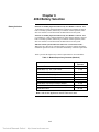
Battery Selection
60 Hours of Standby Operation Followed by Ten Minutes of Alarm - With
10 Ah batteries, a fully configured 4004 Fire Alarm System supplies at least 60
hours of standby operation, followed by ten minutes of alarm operation, when
four-wire detectors or non-alarm loads are not connected to the system.
24 Hours of Standby Operation Followed by Ten Minutes of Alarm - With
6.2 Ah batteries, a fully configured 4004 Fire Alarm System supplies at least 24
hours of standby operation, followed by ten minutes of alarm operation, when
four-wire detectors or non-alarm loads are not connected to the system.
4004 Fire Alarm System with 4-Wire Detectors or Non-Alarm Loads –
When four-wire detectors or non-alarm loads are required, complete the battery
calculation equation in Table 4 to determine 4004 battery selection requirements.
Table 3 provides the Supervisory Current requirements for various modules.
Table 3. Module Supervisory Currents (Nominal)
Module
Supervisory
Current
Standard Panel
52 mA
4004-9802, 2 Pt. IDC, Low Current
7 mA
4004-9804, 4 Pt., Low Current
14 mA
4004-9822, 2 Pt. IDC, High Current
14 mA
4004-9824, 4 Pt. IDC, High Current
27 mA
4004-9806, Class A Adapter
N.A.
4004-9808, Annunciator Interface Module
4 mA
4004-9809, 2 Circuit Remote Station/City Connect
12 mA
2080-9045 DACT
35 mA
Note: Add all NAC Appliances and IDC Devices for total.
Continued on next page
6-1
Technical Manuals Online! - http://www.tech-man.com
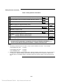
Battery Selection Calculation
Table 4. Battery Selection Calculation
1 Enter total supervisory current from all cards in system (See Table 3)
Amps
2 Enter total Auxiliary power current draw in standby (See Note 1, below)
Amps
3 Enter total two-wire detector current draw in standby (See Note 2, below)
Amps
4
ADD lines [1], [2], and, [3] (Total standby current)
5 Enter the required hours of standby
Amps
=
Ah
=
Ah
=
Ah
Hr
6 MULTIPLY line [4] by line [5]
7 Enter the total NAC/AUX alarm current
Amps
8 MULTIPLY line [7] by .083 for five minutes of alarm
–or–
=
line [7] by .167 for ten minutes of alarm
9 ADD lines [6] and [8]
• If the total in line [9] is less than or equal to 5.1, use 2081-9272 6.2 Ah batteries.
• If the total in line [9 is greater than 5.1 and less than or equal to 8.3, use 2081-9274 10 Ah batteries.
• If the total in line [9 is greater than 8.3, the 4004 charger is not capable of charging larger capacity batteries.
Consider using the 4004 with a 4009 NAC Power Extender or a 4005 Fire Alarm Control Panel.
Notes:
1. All Auxiliary loads subtract from the total 4.0 Amps of power available on the 4004. As an example:
2.
Total Available NAC power
= 4.0 Amps
Total Available AUX power
= 2.0 Amps
Total COMBINED power
= 4.0 Amps
Standby current is listed on Detector Data Sheets. Maximum standby current draw on the “low current” IDC is
2 mA per zone. Maximum standby current draw on the “high current” IDC is 3 mA per zone. Refer to UL's
two-wire detector compatibility listing for compatible models and maximum quantity of two-wire detectors per
zone.
6-2
Technical Manuals Online! - http://www.tech-man.com
Technical Manuals Online! - http://www.tech-man.com
Rev. C
Simplex Time Recorder Co.
Simplex Plaza
Gardner, Massachusetts
Technical Manuals Online! - http://www.tech-man.com
01441-0001
U.S.A.
574-074