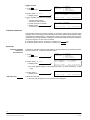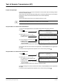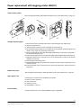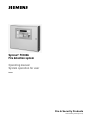
1
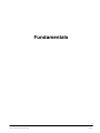
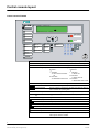
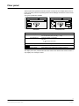
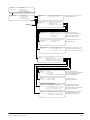
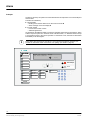
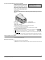
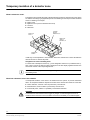
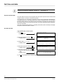
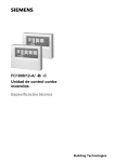
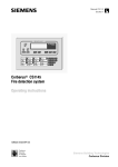
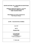
Synova® FC330A
Fire detection system
Operating manual
System operation for user
Phase 4
Fire & Security Products
Siemens Building Technologies Group
Data and design subject to change
without notice. / Supply subject to
availability.
E Copyright by
Siemens Building Technologies AG
Wir behalten uns alle Rechte an
diesem Dokument und an dem in ihm
dargestellten Gegenstand vor. Der
Empfänger anerkennt diese Rechte
und wird dieses Dokument nicht ohne
unsere vorgängige schriftliche
Ermächtigung ganz oder teilweise
Dritten zugänglich machen oder
ausserhalb des Zweckes verwenden,
zu dem es ihm übergeben worden ist.
We reserve all rights in this document
and in the subject thereof. By
acceptance of the document the
recipient acknowledges these rights
and undertakes not to publish the
document nor the subject thereof in
full or in part, nor to make them
available to any third party without our
prior express written authorization,
nor to use it for any purpose other
than for which it was delivered to him.
Nous nous réservons tous les droits
sur ce document, ainsi que sur l’objet
y figurant. La partie recevant ce
document reconnaît ces droits et elle
s’engage à ne pas le rendre
accessible à des tiers, même
partiellement, sans notre autorisation
écrite préalable et à ne pas
l’employer à des fins autres que
celles pour lesquelles il lui a été
remis.
Ci riserviamo ogni diritto relativo al
presente documento e sull’oggetto
illustrato in esso. La parte che riceve
il documento si impegna a non
renderlo accessibile a terzi, né per
intero né in parte, senza la nostra
previa autorizzazione scritta ed a non
usarlo per altri scopi di quello per il
quale è stato rilasciato.
Introduction . . . . . . . . . . . . . . . . . . . . . . . . . . . . . . . . . . . . . . . . . . . . .
1
About this operation manual . . . . . . . . . . . . . . . . . . . . . . . . . . . . . . . . . . . . . . . . . . . . . . .
2
Fundamentals . . . . . . . . . . . . . . . . . . . . . . . . . . . . . . . . . . . . . . . . . . .
3
Control console layout . . . . . . . . . . . . . . . . . . . . . . . . . . . . . . . . . . . . . . . . . . . . . . . . . . . .
4
Floor panel . . . . . . . . . . . . . . . . . . . . . . . . . . . . . . . . . . . . . . . . . . . . . . . . . . . . . . . . . . . . . .
5
Overview operating menu . . . . . . . . . . . . . . . . . . . . . . . . . . . . . . . . . . . . . . . . . . . . . . . . .
6
Fundamental operation . . . . . . . . . . . . . . . . . . . . . . . . . . . . . . . . . . . . . . . . . . . . . . . . . . . .
9
Normal operation . . . . . . . . . . . . . . . . . . . . . . . . . . . . . . . . . . . . . . . . . . . . . . . . . . . . . . . . .
10
Operating access . . . . . . . . . . . . . . . . . . . . . . . . . . . . . . . . . . . . . . . . . . . . . . . . . . . . . . . . .
11
Operating “manned” and “unmanned” . . . . . . . . . . . . . . . . . . . . . . . . . . . . . . . . . . . . . . .
13
Alarm . . . . . . . . . . . . . . . . . . . . . . . . . . . . . . . . . . . . . . . . . . . . . . . . . . . 15
Cerberus Alarm Concept (CAC) . . . . . . . . . . . . . . . . . . . . . . . . . . . . . . . . . . . . . . . . . . . .
16
Alarm . . . . . . . . . . . . . . . . . . . . . . . . . . . . . . . . . . . . . . . . . . . . . . . . . . . . . . . . . . . . . . . . . . .
18
Disable/Enable System Parts . . . . . . . . . . . . . . . . . . . . . . . . . . . . . 21
Temporary isolation of a detector zone . . . . . . . . . . . . . . . . . . . . . . . . . . . . . . . . . . . . . .
22
Temporary isolation of a single detector . . . . . . . . . . . . . . . . . . . . . . . . . . . . . . . . . . . . .
26
Remote Transmission . . . . . . . . . . . . . . . . . . . . . . . . . . . . . . . . . . . . . . . . . . . . . . . . . . . . .
28
Alarm devices . . . . . . . . . . . . . . . . . . . . . . . . . . . . . . . . . . . . . . . . . . . . . . . . . . . . . . . . . . . .
30
Faults . . . . . . . . . . . . . . . . . . . . . . . . . . . . . . . . . . . . . . . . . . . . . . . . . . . 31
Faults . . . . . . . . . . . . . . . . . . . . . . . . . . . . . . . . . . . . . . . . . . . . . . . . . . . . . . . . . . . . . . . . . . .
32
Maintenance . . . . . . . . . . . . . . . . . . . . . . . . . . . . . . . . . . . . . . . . . . . . . 33
Detector test . . . . . . . . . . . . . . . . . . . . . . . . . . . . . . . . . . . . . . . . . . . . . . . . . . . . . . . . . . . . .
34
Lamp test . . . . . . . . . . . . . . . . . . . . . . . . . . . . . . . . . . . . . . . . . . . . . . . . . . . . . . . . . . . . . . .
38
Battery load test . . . . . . . . . . . . . . . . . . . . . . . . . . . . . . . . . . . . . . . . . . . . . . . . . . . . . . . . . .
39
Test of acoustic alarm devices . . . . . . . . . . . . . . . . . . . . . . . . . . . . . . . . . . . . . . . . . . . . . .
40
Test of Remote Transmission (RT) . . . . . . . . . . . . . . . . . . . . . . . . . . . . . . . . . . . . . . . . . .
41
Other Functions . . . . . . . . . . . . . . . . . . . . . . . . . . . . . . . . . . . . . . . . . 43
Printer disabling/enabling . . . . . . . . . . . . . . . . . . . . . . . . . . . . . . . . . . . . . . . . . . . . . . . . . .
44
Paper replacement with logging printer B2Q191 . . . . . . . . . . . . . . . . . . . . . . . . . . . . . .
45
Poll alarm counter . . . . . . . . . . . . . . . . . . . . . . . . . . . . . . . . . . . . . . . . . . . . . . . . . . . . . . . .
46
Poll event memory . . . . . . . . . . . . . . . . . . . . . . . . . . . . . . . . . . . . . . . . . . . . . . . . . . . . . . . .
47
Poll user text of zones or elements . . . . . . . . . . . . . . . . . . . . . . . . . . . . . . . . . . . . . . . . . .
48
Poll system status . . . . . . . . . . . . . . . . . . . . . . . . . . . . . . . . . . . . . . . . . . . . . . . . . . . . . . . .
49
Poll configuration data . . . . . . . . . . . . . . . . . . . . . . . . . . . . . . . . . . . . . . . . . . . . . . . . . . . .
50
Printout . . . . . . . . . . . . . . . . . . . . . . . . . . . . . . . . . . . . . . . . . . . . . . . . . . . . . . . . . . . . . . . . .
51
Set time and date . . . . . . . . . . . . . . . . . . . . . . . . . . . . . . . . . . . . . . . . . . . . . . . . . . . . . . . . .
52
I
Fire & Security Products
Siemens Building Technologies Group
06.2003
II
Fire & Security Products
Siemens Building Technologies Group
06.2003
Introduction
1
Fire & Security Products
Siemens Building Technologies Group
e1973c-1
02.2004
About this operation manual
How to use this operation manual
This operation manual describes the use and the operation of the control console FC330A. It
contains all information for the normal user with access level 2 who has to react to alarms, disable and enable parts of the system, etc.
This document contains the following:
Chapter
Introduction
Contents
− General information about this operation manual
Page
1
− How to use this manual
Fundamentals
Fundamental information on the console:
3
− Description of the control console, functions of
the keys
− Description of the floor panels, functions of the
keys
− Overview of the menu structure
− Fundamental operation of the console
− What is normal operation
− How to get access for operation
− Manned and unmanned operation
Alarm
− Organisation of the SPECIAL Alarm Concept
15
− How to read an alarm message
− How to react in an alarm situation
Disable/Enable System Parts
− Temporary isolation of a detector zone/single
detectors, i. e. for repair works
21
− Disabling/Enabling remote transmission
− Disabling/Enabling alarm devices
Faults
− How to react to a fault message
31
− Remedies by the user
Maintenance
Maintenance works carried out by the user e.g.:
33
− Testing detectors
− Testing lamps, batteries, alarm devices, remote transmission
Other functions
− Disabling/Enabling the printer, paper replacement
43
− Printing information
− Polling information, i. e. alarm counter, event
memory, user texts, system status, configuration data
− Setting time and date
How to read this operation manual
This operation manual uses several symbols to guide the user through the manual.
The meanings in detail are:
1. Multi step actions are marked with numbers.
" Single step actions are marked with a triangle.
The result of an action is marked with an arrow.
In body text you will find quotations like display texts, keys or LED−fields or LEDS.
Frequently used keys are shown as they look like on the console, e.g. ok .
2
Fire & Security Products
Siemens Building Technologies Group
e1973c-1
02.2004
Fundamentals
3
Fire & Security Products
Siemens Building Technologies Group
e1973c-2
02.2004
Control console layout
Control console FC330A
1
ALARM
NORMAL OPERATION
2
MON 04.01.99
09:13
4
Acknowledge
5
Reset
Silence/resound horn
3
System on
Remote alarm
fault / off
Alarm delay
off
6
Fault
Alarm horn
fault / off
Premises
manned
7
Remote alarm
active
System fault
Isolation
Detector
test mode
7
8
9
4
5
6
1
2
3
del
0
hm
F1
8
Start/
Stop
F2
ok
9
FC330A
ALARM LED bar
Red LED’s blinking when an alarm signal is pending.
Text display
Displays selection menus as well as alarm and fault messages.
Scroll key
Allows scrolling of alarm messages in the text display.
Acknowledge key
Confirms an alarm or a message (2 variants possible).
Variant 1:
Variant 2:
1st activation
Alarm horns and buzzer
off
1st activation
Buzzer off
2nd activation
Reactivation alarm horns
2nd activation
Alarm horns off
3rd activation
Reactivation alarm horns
Reset key
Resets alarm and fault messages.
Display fields
Indicates the operating state by an LED.
Command fields
Possess a button to change the operating mode and may have an
LED to indicate the operating state.
Alarm delay off
Cancels alarm delay. Remote alarm is given immediately.
Premises manned
key
Toggles between “manned” and “unmanned” operating mode.
Function keypad
Keys for menu−orientated operation and password input.
St
Start/Stop key
Open and close menus.
F1 F2
Function keys
Usage depends on context.
ok
Execution key
Starts the selected menu function.
Move up/down key
Selects menu items upwards/downwards.
hm
Home key
Returns to the previous menu.
del
Delete key
Deletes the character left of the cursor.
Keylock switch
Gives access to user operating level 2 without password. Only
when keylock switch is installed.
4
Fire & Security Products
Siemens Building Technologies Group
e1973c-2
02.2004
Floor panel
The floor panel is a typical local indication terminal. It mainly serves to display alarm events remotely. Secondary it is also an operating terminal to acknowledge and reset the control console
from remote.
Two types of panels are available:
1
ALARM zone ###/## / ######
1st floor office 101
1
1( 1)
ALARM zone ###/## / ######
1st floor office 101
1( 1)
Alarm
Alarm
Remote alarm
actuated
Fault
LED 1
2
System ON
Acknowledge
Reset
2
LED 2
LED 3
B3Q580
3
4
5
B3Q590/595
Text display
Displays alarm messages.
Scroll key
Allows scrolling of alarm messages in the text display.
Acknowledge key
Also to initiate lamp test (press key w 3 sec).
Confirms an alarm or a message.
activation
Alarm horns and buzzer
off
Reset key
Resets alarm messages.
Display fields
Indicates the operating state by an LED.
Keylock switch
Gives access to user operating level 2 without password.
The display of the floor panel indicates the same event text as shown at the control console. It
only displays one message at a time.
5
Fire & Security Products
Siemens Building Technologies Group
e1973c-2
02.2004
Overview operating menu
After getting operating access, the start menu appears. From the main menu, all menus can be
selected (page 9, fundamental operation).
With access level 2 all menu points exept other functions − configuration can be
selected.
The passwort for access level 2 is:
SELECT:
(main menu)
1.
2.
3.
4.
ENabling
DISabling
INFO polling
other functions
ENABLE:
(1)
1. Detector/ConTrol ZONES
2. horn/RT/alarm contacts
3. printer
ENabling:
(1.1)
ENabling:
(1.2)
1.
2.
3.
4.
1.
2.
3.
4.
detector ’zone’
detector ’element’
ConTrol ’zone’
All Fire Ctrl ’zones’
horn
alarm contacts
RT−alarm
RT−fault
ENable printout messages:
(old: #)
2. only ALARMS
SELECT:
(main menu)
1.
2.
3.
4.
DISabling:
(2)
1. detector/ConTrol ZONES
2. horn/RT/alarm contacts
3. printer
INFO:
(3)
1.
2.
3.
4.
1.
2.
3.
4.
Enable control lines 1...4 for alarm horns
Enable alarm contacts 1...4
Enable remote transmission ALARM
Enable remote transmission FAULT
Enable only event logging or all messages
1. log ALL
3. log NONE Enable only alarms or none
ENabling
DISabling
INFO polling
other functions
DISabling:
(2.1)
1.
2.
3.
4.
detector ’zone’
detector ’element’
ConTrol ’zone’
All Fire Ctrl ’zones’
Disable detector zones 1...256
disabling permanent or for a set time 1...98h
Disable detector ELEMENTS within zone
disabling permanent or for a set time 1...98h
Disable conTrol zones 1....64
Disable all control zones
DISabling:
(2.2)
1.
2.
3.
4.
horn
alarm contacts
RT−alarm
RT−fault
Disable control line 1..4 for alarm horns
Disable alarm contacts 1...4
Disable remote transmission ALARM
Disable remote transmission FAULT
ENable printout messages:
(old: #)
2. only ALARMS
SELECT:
(main menu)
Enable detector zones 1...256
Enable detector elements within zone
Enable control zones 1...64
Enable all control zones
1. log ALL Disable only event logging or all messages
3. log NONE Disable only alarms or none
ENabling
DISabling
INFO polling
other functions
system status
event memory/alarm counter
configuration/user text
configuration zone/line/LON
STATUS: 1. fault
(3.1)
2. isolation
3. pre−alarm
4. techn.alarm /element status
View fault messages
View turned off system components
View pre-alarm messages
View ELEMENT states
MEMORY: 1. event memory
(3.2)
2. alarm counter
View reviewing event list
View number of alarms and remote alarms
INFO:
(3.3)
1.
2.
3.
4.
configuration system
configuration coll line
user text detector zn/elem
user text ConTrol zone
INFO:
(3.4)
1. configuration det. zones
2. configuration addr. lines
3. configuration LON devices
View general parameter settings
View parameter settings coll. lines
View user texts detector zones/elements
View user texts control zones
View parameter settings detector zones
View parameter settings addr. lines
View parameter settings LON-bus
6
Fire & Security Products
Siemens Building Technologies Group
e1973c-2
02.2004
SELECT:
(main menu)
FUNCTIONS:
(4)
1.
2.
3.
4.
ENabling
DISabling
INFO polling
other functions
1.
2.
3.
4.
function
system TEST
printout
configuration
page 8
FUNCTIONS:
(4.1)
1. switching alarm org.
2. set time / date
SYSTEM TEST:
(4.2)
1. horn/al.contact/RT
2. lamps/battery
3. fire and contr.zones
SYSTEM TEST:
(4.2.1)
1.
2.
3.
4.
SYSTEM Test:
(4.2.2)
1. lamps/display
2. battery
SYSTEM TEST:
(4.2.3)
1. single zone test
2. zone range test
3. set control zones
PRINT:
(4.3)
1.
2.
3.
4.
Switching manned $ unmanned via menu
Set or adjust time and date
horn
alarm contacts
RT−alarm
RT−fault
Activate all ’horns’ for 30 sec
Activate all ’alarm contacts’ for 30 sec.
Activate ’remote alarm’ for 30 sec.
Activate ’remote fault’ for 30 sec.
Activate all LEDs and LCD for 10 sec.
Load battery for 10 sec.
Set detectors to ’Detector test’ per zone
Set detectors to ’Detector test’ zone X...Y
Set control zone to ’control zone Test’ X..Y
system status
event memory/alarm counter
configuration/user text
configuration zone/line/LON
PRINT: 1. fault
(4.3.1) 2. isolation
3. pre−alarm
4. techn.alarm /element status
Print current fault messages
Print current turned off system components
Print current information messages
Print current ELEMENT states
PRINT: 1. event memory
(4.3.2) 2. alarm counter
Print event memory list
Print alarm counter readings
PRINT: 1. configuration system
(4.3.3) 2. configuration coll. line
3. user text detector zn/elem
4. user text ConTrol zone
Print general parameter settings
Print parameter settings coll. lines
Print user texts detector zones / elements
Print user texts control zones
PRINT: 1. configuration det. zones
(4.3.4) 2. configuration addr. lines
3. configuration LON devices
Print parameter settings detector zones
Print parameter settings addr. lines
Print parameter settings LON-bus
7
Fire & Security Products
Siemens Building Technologies Group
e1973c-2
02.2004
SELECT:
(main menu)
FUNCTIONS:
(4)
1.
2.
3.
4.
ENabling
DISabling
INFO polling
other functions
1.
2.
3.
4.
function
system TEST
printout
configuration
CONFIGURATION:
(4.4)
1.
2.
3.
4.
user functions
user text
service functions
erase functions
direct setting user parameters
direct definition user texts
Level SERVICE FUNCTIONS
> enter password?
only for service
engineer
hm: back to menu
SERVICE
level :
(4.4.3)
Stop: end operating
1.
2.
3.
4.
addr. line −> CONNECT
addr. line −> DISCON.
test AI−LED’s ON/OFF
reconfigure addr. lines
5.
6.
7.
8.
horn/ctrl/RT −> OFF
TEST−alarm −> HORN
Visualizer ON/OFF
re−parametrise LON
connect addressable loop
disconnect addressable loop
for TEST LEDs
to reconfigure addr. lines
for COMMON disabling
to activate horn briefly with each det.
TEST alarm
enable / disable ’visualizer’
to start automatic configuration of LONBus
Level SERVICE FUNCTIONS
> enter password?
hm: back to menu
ERASE data:
(4.4.4)
1.
2.
3.
4.
Stop: end operating
ERASE
ERASE
ERASE
ERASE
alarm counter
event memory
conf + sys data
element status
(locked with switch ’S2’)
(not locked)
only for specialized personell
to erase ’non−alarm’ events
8
Fire & Security Products
Siemens Building Technologies Group
e1973c-2
02.2004
Fundamental operation
How to operate the control console
To choose a menu item in the display of the console:
1. Press St .
Display shows
START system operating
> enter password?
hm /Stop: end operating
Access level + page 11
2. Enter the password and press
Display shows
ok
.
SELECT:
(main menu)
1.
2.
3.
4.
ENabling
DISabling
INFO polling
other functions
3. Select the menu item with the
and
keys and press ok .
or
" Enter the number of the menu option on the numeric keypad (e. g. option 2.).
Display shows
DISabling:
1. detector/ConTrol
4. Repeat the selection until the required
menu is displayed.
(2)
ZONES
2. horn/RT/alarm contacts
3. printer
5. Follow the instructions on the display.
6. Finish the operation by pressing St .
or
" Press hm to return to the previous menu.
Example
The following description is an example for choosing the Disable elements menu.
1. Press
St
.
2. Log in.
Display shows
3. Select option 2. with the
and press ok .
or
" Enter “2”.
Display shows
and
4. Select option 1. with the
and press ok .
or
" Enter “1”.
Display shows
and
5. Select option 2. with the
and press ok .
or
" Enter “2”.
Display shows
and
SELECT:
(main menu)
1.
2.
3.
4.
DISabling:
(2)
1. detector/ConTrol ZONES
2. horn/RT/alarm contacts
3. printer
DISabling:
(2.1)
1.
2.
3.
4.
keys
ENabling
DISabling
INFO polling
other functions
keys
keys
detector ’zone’
detector ’element’
ConTrol ’zone’
All Fire Ctrl ’zones’
DISABLE element:
> zone no.? (range ### − ###)
hm: back to menu
Stop: end operating
Actions in the operation manual
In this operation manual, selecting a menu item will be described from now on in a short form as
follows:
" Select option 2. 1. 2.
DISABLE element:
> zone no.? (range ### − ###)
Display shows
hm: back to menu
Stop: end operating
9
Fire & Security Products
Siemens Building Technologies Group
e1973c-2
02.2004
Normal operation
What is “normal operation”?
The system is ready to receive danger messages (alarm) from the detectors.
No fault messages are pending.
The green LED in the display field System on is on.
The illumination of the text display may be turned off, but turns on as soon as any key is
pressed or an alarm, fault or status is issued.
NORMAL OPERATION
Display shows
WED 21.7.99
15:00
Mains interruption
In case of a mains interruption the fire detection system is powered by an internal battery. No
fault message is issued in the text display and the normal operation will continue , until a preset
default time is expired
When the system is powered by the internal battery the green LED in the display field System on
is blinking.
The delay is
min
Standard default: 10 min
ALARM
NORMAL OPERATION
2
WED 21.7.99
15:00
Acknowledge
Silence/resound horn
Reset
1
System on
Remote alarm
fault / off
Alarm delay
off
Fault
Alarm horn
fault / off
Premises
manned
Isolation
System fault
Detector
test mode
Remote alarm
active
7
8
9
F1
4
5
6
F2
1
2
3
ok
del
0
hm
Start/
Stop
FC330A
10
Fire & Security Products
Siemens Building Technologies Group
e1973c-2
02.2004
Operating access
Possible access levels
Three main access levels are defined allowing different privileges for the operation of the fire
detection system. Access is provided by a four digit password for the higher access levels, respectively.
i
After 3 consecutive incorrect password entries the operation access is disabled for 15 minutes.
Overview of the access levels
Access level
Acknowledge messages
possible:
with access level 1 p
with access level 2 p
Access level 1
Group of persons
everybody
− Scrolling alarm messages
− Acknowledge messages
(no password)
Access level 2
(password required or
key−lock switch, if installed)
Enabled operating functions
system operator 1 (e. g. janitor)
− Acknowledge messages
− Alarm reset
− Fault/Info scrolling
− Isolation of system parts
− Poll system information
− Perform system tests
Access level 3
(various passwords to distinguish)
service engineer
− Edit user text
or
system operator 2 (e. g. security officer)
service engineer
− Service functions
− Erase data
service engineer
− Application setting
− Setting passwords
Automatic timeout
The access by password is automatically cancelled if no key is operated for:
5 min during state of “normal operation“
30 sec during condition “alarm“
How do I get operating access?
Enter the password on the keypad as described below.
or
" Turn the keylock switch in horizontal position.
Access with level user operating 2 is provided as long as the key is left in horizontal position.
"
System on
Remote alarm
fault / off
Alarm delay
off
Fault
Alarm horn
fault / off
Premises
manned
Isolation
System fault
Detector
test mode
Remote alarm
active
7
8
9
4
5
6
1
2
3
del
0
hm
F1
1
Start/
Stop
F2
ok
2
FC330A
11
Fire & Security Products
Siemens Building Technologies Group
e1973c-2
02.2004
Operating access via password
The passwords are defined and released to the operators by the service engineer.
In case of misskeying the password, use del to cancel keying errors.
Log in
START system operating
> enter password?
1. Press St .
Display shows
hm /Stop: end operating
2. Enter the password and press
Display shows
ok
.
SELECT:
(main menu)
1.
2.
3.
4.
ENabling
DISabling
INFO polling
other functions
3. Proceed operating (access is now provided)
Log out
There is no log out procedure, because the operating access expires automatically if no key is
pressed within a certain time (page 11, Automatic timeout).
12
Fire & Security Products
Siemens Building Technologies Group
e1973c-2
02.2004
Operating “manned” and “unmanned”
i
SPECIAL Alarm Concept used:
Yes No Basic rules
The operating states “manned” and “unmanned” are defined in a SPECIAL Alarm Concept,
where signals from automatic fire detectors and manual call points are processed differently (for
details page 16).
The switchover from the operating states “manned” to “unmanned” and vice versa is either done
manually by the operating personnel or automatically as programmed by the service engineer.
Operating state “manned”
The operating person, responsible for the surveillance of the system and the alarm investigation, is present on the premises.
The LED in the display field Premises manned is on.
The LED in the display field Isolation is on (depends on system configuration).
Operating state “unmanned”
The responsible operating person is not present on the premises.
The LED in the display field Premises manned is off.
System on
Remote alarm
fault / off
Alarm delay
off
Fault
Alarm horn
fault / off
Premises
manned
Isolation
System fault
Remote alarm
active
1
Detector
test mode
7
8
9
F1
4
5
6
F2
1
2
3
ok
del
0
hm
Start/
Stop
FC330A
Manual switching between the operating states “manned” and “unmanned”
i
Manual switching between the operating states “manned” and “unmanned” is only possible
during defined working hours (page 14, Automatic switchover).
1. Log in with ”access level 2”.
2. Press the Premises manned key on the control panel to toggle between the operating states
“manned” (yellow LED is on) and “unmanned” (yellow LED is off).
or
" Toggle between “manned” and “unmanned” via menu which is described next page.
Operating state ”unmanned”
Display shows
NORMAL OPERATION
WED 21.7.99
Operating state ”manned”
Display shows
15:00
NORMAL OPERATION
mode ’manned’
WED 21.7.99
15:00
13
Fire & Security Products
Siemens Building Technologies Group
e1973c-2
02.2004
Toggle via menu
SELECT:
(main menu)
1. Press St .
Display shows
2. Select option 4. 1. 1.
Display shows
3. If the operating state has to be changed
to
− “manned”: select option 1.
− “unmanned”: select option 2.
If mode ”manned” is selected
Display shows
for a few seconds
1.
2.
3.
4.
ENabling
DISabling
INFO polling
other functions
mode ’manned’ until ##:##, 1.> unmanned
sel. #,
2.> manned
3.extra time
hm: back to menu
Stop: end operating
mode ’manned’ TERMINATED
> system is set to NORMAL OPERATION
timeout /hm: menu
Stop: end operating
Automatic switchover
The automatic switchover is used for example, to prevent the system status “manned” during
nighttime when no operating personnel is present: The system switches automatically to status
“unmanned” at a defined time (e. g. after the office hours). The same scheme can be used for
unattended times during weekends or holidays. The automatic switchover scheme is defined by
the service engineer. No user action is required.
Automatic switchover from “manned” to “unmanned”: at
p.m.
Automatic switchover from “unmanned” to “manned”: at
a.m.
Extra time
Function extra time
activated p
not activated p
The function “extra time” allows to set the system to manned operation for a preset time, after the
automatic switchover to unmanned has taken place.
1. Press St .
Display shows
2. Select option 4. 1. 1.
Display shows
SELECT:
(main menu)
1.
2.
3.
4.
ENabling
DISabling
INFO polling
other functions
mode ’unmanned’
(hm = INTERRUPT)
2. > ’manned’
3. extra time
hm: back to menu
Stop: end operating
The actual display depends on the initial mode, here e. g. mode unmanned (i. e. after
17:00).
3. Select option 3.
Display shows
EXTRA TIME h/min? (max. ##:##)
hm: back to menu
Extra time max.
Stop: end operating
4. Enter the extra time.
The time until the system is set to manned mode is displayed.
14
Fire & Security Products
Siemens Building Technologies Group
e1973c-2
02.2004
Alarm
15
Fire & Security Products
Siemens Building Technologies Group
e1973c-3
02.2004
SPECIAL Alarm Concept
Purpose and principle
To prevent the unnecessary turn out of the fire department for minor incidents a SPECIAL Alarm
Concept was developed.
It involves operating personnel in the alarming sequence and relies on two operating states:
“unmanned” mode
while the operating personnel is not present on the premises.
“manned” mode
while the operating personnel is present on the premises.
“unmanned” mode
When the system operates in “unmanned” mode, the fire brigade is called immediately when an
alarm signal is issued.
“manned” mode
When the system operates in “manned” mode, manual call points and automatic detectors trigger different actions in the event of an alarm:
Event
Action
Manual call point is actuated
The fire brigade is summoned immediately.
Automatic fire detector responds
The fire brigade is summoned only after a preprogrammed
time in which the operating personnel performs following
alarm response procedure:
1. Confirm the alarm within the alarm acknowledgement time
V1 (press the Acknowledge key).
2. Read the alarm locations on the text display.
3. Go to these locations immediately.
4. Decide at the face whether this is an emergency or a minor
incident.
i
Emergency
"
Minor incident
Reset the system before expiration of the alarm investigation
time V2 by pressing the Reset key.
The system is in the normal operation mode again.
Actuate the nearest manual call point immediately!
or
" Press the Alarm delay off key on the control console!
The fire brigade is summoned immediately.
The times V1 and V2 are only relevant, when the remote transmission is installed.
16
Fire & Security Products
Siemens Building Technologies Group
e1973c-3
02.2004
V1 =
min.
Alarm acknowledgement time V1
The alarm acknowledgement time is active for automatic detectors when the system operates in “manned” mode.
The system checks whether someone acknowledges the alarm message within this preprogrammed time.
An alarm must be acknowledged before V1 expires, otherwise the alarm is transmitted to the
fire department.
The remaining time is indicated on the text display in minutes and seconds.
ALARM zone ###/## / ######
1:27 min
1 ( 1)
V2 =
min.
Alarm investigation time V2
The alarm investigation time is active for automatic detectors when the system operates in
“manned” mode.
It limits the time for investigating the fire location to an preprogrammed length.
On expiration of this time the alarm is transmitted to the fire department.
In case of minor incidents, an alarm must be reset before V2 expires.
The remaining time is indicated on the text display in minutes and seconds.
ALARM zone ###/## / ######
2:27 min
1 ( 1)
17
Fire & Security Products
Siemens Building Technologies Group
e1973c-3
02.2004
Alarm
Principle
An alarm is issued by the system if an automatic detector has responded or a manual call point
was actuated.
The alarm is indicated by:
optical signals
− blinking of the red LED alarm bar on the control console − alarm message on the text display acoustic signals
− buzzer of the control console
− attached signal horns
As described in the SPECIAL Alarm Concept, the operating personnel is involved into the alarm
scheme only if the system is in “manned” mode. In all other cases, i. e. SPECIAL Alarm Concept
is not activated (used) or the system operates in “unmanned” mode, the alarm is transmitted
immediately to the fire brigade.
i
1
During alarm other states such as faults etc. are not shown at the display. However, it is
possible to make them visible via the menu “Info polling” (For details page 49).
ALARM
ALARM zone ###/## / ######
1st floor canteen
2
1( 1)
3
System on
Remote alarm
fault / off
Alarm delay
off
Fault
Alarm horn
fault / off
Premises
manned
Isolation
System fault
Detector
test mode
6
Remote alarm
active
4
Acknowledge
5
Reset
Silence/resound horn
7
8
9
F1
4
5
6
F2
1
2
3
ok
del
0
hm
Start/
Stop
FC330A
18
Fire & Security Products
Siemens Building Technologies Group
e1973c-3
02.2004
How are alarm messages shown on the text display?
A single alarm message on the text display ALARM zone ###/## / ######
1( 3)
consists of 2 lines as shown in the example to
1st floor canteen
the right.The first line tells that the alarm was ALARM zone ###/## / ######
3( 3)
ground floor main entrance
given in zone 5 by the element 1 of this zone,
which was an automatic fire detector. The
numbers at the end of the line tell, that this is
the first of in total 3 alarm messages. The second line gives the explicit location of the responding detector.
The 3. and the 4. line hold the same information for the last alarm message issued. In this case a
manual call point was actuated in zone 3 of the building, which is located in the ground floor main
entrance.
1. alarm message
zone 5, element 1
”1st floor canteen”
3. alarm message
zone 3, element 1
”ground floor main entrance”
Scrolling alarm messages
Additional pending messages can be retrieved using the scroll key.
" Press the scroll key below the text display.
The first two lines are superseeded with the subsequent alarm message.
Retrieving supplementary informations
Supplementary informations to the alarm messages can be retrieved by using F1 and F2 :
F1 tells the type of the responding device, e. g. automatic detector.
F2 tells the cabling address and the type number of the responding device (device address).
"
"
Press F1 (or F2 ).
The second line in the text display is superseeded with the supplementary information.
Press the scroll key to retrieve supplementary information of subsequent alarm messages.
How to respond in case of alarm
1. Press the Acknowledge key .
What to do after an alarm
"
"
Reset system if normal conditions appeared.
If a manual call point was activated while the alarm, insert a new front glass in the actual call
point.
19
Fire & Security Products
Siemens Building Technologies Group
e1973c-3
02.2004
20
Fire & Security Products
Siemens Building Technologies Group
e1973c-3
02.2004
Disable/Enable System Parts
21
Fire & Security Products
Siemens Building Technologies Group
e1973c-4
02.2004
Temporary isolation of a detector zone
What is a detector zone?
The detectors and manual call points of the fire detection system are grouped into zones, which
are defined according to geographical aspects of the building. Zones may be all self-contained
areas of a building, for example
single rooms
adjacent rooms (no doors between the rooms)
corridors
staircases
Room 101
Zone 1
Corridor
Zone 5
element 1,2,3
Room 104
Zone 4
element 1,2
Room 102
Zone 2
2nd floor
In that way, a zone represents a “room address”. Each zone contains one or more automatic fire
detector devices or manual call points.
Assignment of zones to building areas
For each zone a descriptive user text (e. g. room designation and floor no.) is defined in the system. Only in case of an alarm, this text is displayed on the text display together with the zone
and device number of the responding detector.
i
It is recommended to prepare a list holding the assignment of zone numbers to actual rooms
and building-areas.
When has a detector zone to be isolated?
In exceptional situations zones have to be isolated from the system, to prevent unintended
alarm. An exceptional situation depends on the kind of the detector and exists for zones with:
smoke detectors, if smoke or dust is produced by unusual work
heat detectors, if heat or steam is produced by unusual work
manual call points, if there is a possibility of inadvertent activation
WARNING
A zone that has been isolated cannot trigger any danger or fault messages! As soon as
conditions have returned to normal, isolated zones have immediately to be enabled again!
22
Fire & Security Products
Siemens Building Technologies Group
e1973c-4
02.2004
Zone isolation procedure
1. Press St .
Display shows
SELECT:
(main menu)
2. Select option 2. 1. 1.
Display shows
Now you can disable single zones, a range of
detector zones or all zones as described below:
1.
2.
3.
4.
ENabling
DISabling
INFO polling
other functions
DISable zones: (range ### to ###)
> zone no.? (555 = all)
hm: back to menu
Stop: end operating
Disable single zones
1. Enter the desired zone number (e. g.
2).
Display shows
Permanent disabling
2. Press ok to disable the single zone.
Display shows
3. Enter 99 for permanent disabling.
Display shows
hm: back to menu
zone ### SELECTED
> hours DISABLED?
Enter the desired disabling time in full
hours (e. g. 2).
Display shows
Stop: end operating
(99=permanent)
zone ### permanent DISABLED
(hm = end)
new zone no.?
hm: back to menu
or
Disabling for a few
hours
zone ### SELECTED. ok = SINGLE zone
> 2nd zone no.? (range ### − ###)
Stop: end operating
"
zone ### DISABLED for ## hours
(hm = end)
new zone no.?
hm: back to menu
4. Press St to finish the zone disabling
procedure.
or
" Enter another single zone number to disable.
Display shows
The yellow LED isolation is on.
Stop: end operating
parts of system DISABLED
WED 21.7.00
total:###
15:00
Disable a range of zones
1. Enter the first zone number of the
range of zones to be disabled (e. g. 2).
Display shows
zone ### SELECTED. ok = SINGLE zone
> 2nd zone no.? (range ### − ###)
_
hm: back to menu
2. Enter the last zone number of the range
of zones to be disabled (e. g. 5).
Display shows
zone ### − ### SELECTED
> hours DISABLED? (99=permanent)
hm: back to menu
Permanent disabling
3. Enter 99 for permanent disabling.
Display shows
or
Disabling for a few
hours
Enter the desired disabling time in full
hours (e. g. 2).
Display shows
Stop: end operating
Stop: end operating
zones ### − ### permanent DISABLED
(hm = end)
new zone no.?
hm: back to menu
Stop: end operating
"
4. Press St to finish the zone disabling
procedure.
or
" Enter another zone number to disable.
Display shows
The yellow LED isolation is on.
zones ### − ### DISABLED for ## hours
(hm = end)
new zone no.?
hm: back to menu
Stop: end operating
parts of system DISABLED
WED 21.7.00
total:###
15:00
23
Fire & Security Products
Siemens Building Technologies Group
e1973c-4
02.2004
Disable all zones
Permanent disabling
1. Enter 555 to disable all zones in the
building.
Display shows
2. Enter 99 for permanent disabling.
Display shows
zone ### − ### SELECTED
> hours DISABLED? (99=permanent)
hm: back to menu
Stop: end operating
zone ### permanent DISABLED
(hm = end)
new zone no.?
hm: back to menu
Stop: end operating
or
Disabling for a few
hours
Enter the desired disabling time in full
hours (e. g. 2).
Display shows
"
zone ### DISABLED for ## hours
(hm = end)
new zone no.?
hm: back to menu
3. Press St to finish the zone disabling
procedure.
Display shows
The yellow LED isolation is on.
Stop: end operating
parts of system DISABLED
total:###
WED 21.7.00
15:00
Viewing disabled zones
Several zones disabled
Display shows
parts of system DISABLED
WED 21.7.00
1. Press key F1 to open list.
Display shows
15:00
display ISOLATIONS:
total:###
(key: ↓ = forward / ↑ = backward)
F1: next section
2. Press key
to view details.
Display shows
stem turns back to overview.
Display shows
hm/Stop: end operating
display ISOLATIONS:
total:###
zone ### − ### permanent DISABLED
↓: forward
After last zone has been displayed, sy-
total:###
F2:ext info
parts of system DISABLED
↑: backwards
total:###
WED 21.7.00
15:00
Zone reactivation procedure
1. Press St .
Display shows
2. Select option 1. 1. 1.
Display shows
The yellow LED isolation is off.
SELECT:
(main menu)
1.
2.
3.
4.
ENabling
DISabling
INFO polling
other functions
ENable zone: (range ### to ###)
> zone no.? (555 = all)
hm: back to menu
Stop: end operating
24
Fire & Security Products
Siemens Building Technologies Group
e1973c-4
02.2004
Enable single zones
1. Enter the number of a zone to be enabled (e. g. 2).
Display shows
With a running timeout after which the
zone is automatically enabled.
2. Enter another zone number to enable
or press F1 to enable the zone before
the timeout has expired.
Display shows
for a few seconds
or
3. Press hm to go back to the submenu.
Display shows
MONITORING zone ###, wait.
(F1 /hm = enabling) next zone?
ENable zones:
> all zones ENABLED
timeout /hm: menu
ENabling:
(1.1)
1.
2.
3.
4.
Stop: end operating
detector ’zone’
detector ’element’
ConTrol ’zone’
All Fire Ctrl ’zones’
Enable a range of zones
1. Enter the first number of a zone range
to be enabled (e. g. 2).
Display shows
2. Enter the last number of the zone range
(e. g. 5).
Display shows
With a running timeout after which the
zone range is automatically enabled.
3. Press F1 to enable all zones before the
timeout has expired.
Display shows
for a few seconds
or
4. Press hm to go back to the submenu.
Display shows
ENable zone range ### to ###
> confirm LAST zone no.?
MONITORING zones ###−###, wait
(F1 /hm = enabling) > LAST zone
ENable zones:
> all zones ENABLED
timeout /hm: menu
DISabling:
(2.1)
1.
2.
3.
4.
Stop: end operating
detector ’zone’
detector ’element’
ConTrol ’zone’
All Fire Ctrl ’zones’
Enable all disabled zones
1. Enter 555 to enable all disabled zones,
no matter if all zones, a range of zones
or single zones were disabled.
Display shows
With a running timeout after which all
zones are automatically enabled.
2. Press F1 to enable all zones before the
timeout has expired.
Display shows
for a few seconds
or
3. Press hm to go back to the submenu.
Display shows
MONITORING zone ###, wait
(F1 /hm = enabling) > LAST zone
ENable zones:
> all zones ENABLED
timeout /hm: menu
DISabling:
(2.1)
1.
2.
3.
4.
Stop: end operating
detector ’zone’
detector ’element’
ConTrol ’zone’
All Fire Ctrl ’zones’
25
Fire & Security Products
Siemens Building Technologies Group
e1973c-4
02.2004
Temporary isolation of a single detector
When has a single detector to be isolated?
Exceptional situations may occur, where it is preferable to isolate only single detector devices
instead of the whole detector zone. Such situations may be for example:
Construction work with smoke or heat development at a particular location within a large
zone with a lot of detectors
Malfunction of a detector in a zone with several detector devices
WARNING
A detector device that has been isolated cannot trigger any danger or fault messages! As
soon as conditions have returned to normal, isolated detector devices have immediately to
be switched on again!
i
If a single detector should be isolated the detector has to be identified clearly! If the detector
cannot be identified clearly, the whole detector zone should be isolated. A wrong isolation of
a detector can cause an unwelcome call of the fire brigade!
Single detector isolation procedure
1. Press St .
Display shows
2. Select option 2. 1. 2.
Display shows
SELECT:
(main menu)
1.
2.
3.
4.
DISABLE element:
> zone no.? (range ### − ###)
hm: back to menu
3. Enter the desired zone number.
Display shows
Stop: end operating
zone ### element ## SELECTED
> hours disabled? (99=permanent)
hm: back to menu
5. Enter the desired disabling time in full
hours or 99 for permanent disabling.
Display shows
The yellow LED isolation is on.
Stop: end operating
zone ### SELECTED
> element no.? (range ## − ##)
hm: back to menu
4. Enter the desired element number.
Display shows
ENabling
DISabling
INFO polling
other functions
Stop: end operating
zone ### elem. ## permanent DISABLED
> new element no.? (range ## − ##)
hm: back to menu
Stop: end operating
6. Press hm to finish the element disabling procedure or enter a new zone
number to disable another single element.
26
Fire & Security Products
Siemens Building Technologies Group
e1973c-4
02.2004
Detector reactivation procedure
1. Press St .
Display shows
2. Select option 1. 1. 2.
Display shows
SELECT:
(main menu)
1.
2.
3.
4.
ENabling
DISabling
INFO polling
other functions
ENABLE element: (zone range ### − ###)
> zone no.?
hm: back to menu
3. Enter the desired zone number.
Display shows
ENABLE single element in zone ###:
> element no.? (range ## − ##)
timeout /hm: menu
4. Enter the desired element number.
Display shows
Stop: end operating
Stop: end operating
MONIT. zone ### elem. ##, WAIT
(F1 /hm = enabling) next elem.?
5. Enter another element number to enable
or
6. Press F1 to enable the element before
the timeout has expired.
or
7. Press
hm
to go back to the submenu.
27
Fire & Security Products
Siemens Building Technologies Group
e1973c-4
02.2004
Remote Transmission
i
Remote transmission provided:
Fault transmission provided:
No No Yes Yes Alarm to:
Alarm to:
What is “remote transmission”?
The remote transmission facility establishes a transmission path to the fire department in the
event of a fire alarm issued by the fire detection system. Depending on the alarm concept, the
alarm is transmitted immediately to the fire department, or after a certain delay, giving time for
investigation by operating personnel.
In single cases a separate transmission path for fault messages is established.
When has the remote transmission to be disabled?
Under normal conditions the remote alarm transmission facility is enabled to ensure minimal
alarming times. The remote transmission facility is disabled only in special cases to prevent unnecessary turn out of the fire brigade. The transmission facility should be disabled for:
Test of the fire detection system
Maintenance and conversion works on the fire detection system
WARNING
When the remote alarm transmission is disabled, no automatic alarm is transmitted to the
fire department! Operating personnel must be on the premises to investigate immediately
the location in case of an alarm and to alarm the fire department in case of fire!
Disabling the remote alarm transmission facility
SELECT:
(main menu)
1. Press St .
Display shows
2. Select option 2. 2. 3.
Display shows
3. Enter the desired disabling time or 99
for permanent disabling.
Display shows
for a few seconds
1.
2.
3.
4.
ENabling
DISabling
INFO polling
other functions
DISABLE RT−alarm:
> hours DISABLED?
hm: back to menu
(99=permanent)
Stop: end operating
RT−alarm permanent DISABLED
timeout /hm: menu
Stop: end operating
The remote fire alarm transmission is disabled.
The yellow LEDs of the display fields Isolation and Remote alarm/fault off are on.
The text display indicates that no alarm message is pending.
Enabling the remote alarm transmission facility
1. Press St .
Display shows
2. Select option 1. 2. 3.
Display shows
for a few seconds
SELECT:
(main menu)
1.
2.
3.
4.
ENabling
DISabling
INFO polling
other functions
RT−alarm ENABLED
timeout /hm: menu
Stop: end operating
The remote fire alarm transmission is enabled.
The yellow LEDs of the display fields Isolation and Remote alarm/fault off are off, if no other
parts of the system are isolated.
28
Fire & Security Products
Siemens Building Technologies Group
e1973c-5
02.2004
Disabling the remote fault transmission facility
1. Press St .
Display shows
SELECT:
(main menu)
2. Select option 2. 2. 4.
Display shows
1.
2.
3.
4.
ENabling
DISabling
INFO polling
other functions
RT−fault DISABLED
for a few seconds
timeout /hm: menu
Stop: end operating
The remote fault transmission is disabled.
The yellow LED of the display field Isolation is on.
The text display indicates that no alarm message is pending.
Enabling the remote fault transmission facility
1. Press St .
Display shows
2. Select option 1. 2. 4.
Display shows
for a few seconds
SELECT:
(main menu)
1.
2.
3.
4.
ENabling
DISabling
INFO polling
other functions
RT−alarm ENABLED
timeout /hm: menu
Stop: end operating
The remote fault transmission is enabled.
The yellow LED of the display filed Isolation is off, if no other parts of the system are isola-
ted.
29
Fire & Security Products
Siemens Building Technologies Group
e1973c-5
02.2004
Alarm devices
When have alarm devices to be disabled?
Under normal conditions the alarm devices (e. g. horns or sirens) operate in active stand−by.
They are only disabled for:
Test of the fire detection system.
Maintenance and conversion works on the fire detection system.
WARNING
When the alarm devices are disabled, no acoustic alarm (except the buzzer) is issued in
case of fire!
i
Normally all acoustic devices are disabled together. Single devices or lines are only disabled in exceptional cases. For the alarm devices there are always 2 lines, in some cases 4
lines, but max. 6 lines possible.
Disabling the alarm devices
SELECT:
(main menu)
1. Press St .
Display shows
2. Select option 2. 2. 1.
Display shows
3. Enter the desired horn number or 555
for disabling all horns.
Display shows
for a few seconds
1.
2.
3.
4.
ENabling
DISabling
INFO polling
other functions
DISABLE horn:
> enter horn no.? (all=555)
hm: back to menu
Stop: end operating
DISABLE horn:
> all horns DISABLED
timeout /hm: menu
Stop: end operating
4. Enter the number of a further device to
disable.
or
" Press St to finish the procedure.
The desired alarm devices are disabled.
The yellow LEDs of the display fields Isolation and Alarm horn fault/off are on.
The text display indicates that no alarm message is pending.
Enabling alarm devices
1. Press St .
Display shows
2. Select option 1. 2. 1.
Display shows
SELECT:
(main menu)
1.
2.
3.
4.
ENabling
DISabling
INFO polling
other functions
ENABLE horn outputs:
> enter horn no.? (all=555)
hm: back to menu
3. Enter the desired horn number or 555
to enable all horns.
Display shows
for a few seconds
Stop: end operating
ENABLE horn outputs:
> all horn outputs ENABLED
timeout /hm: menu
Stop: end operating
4. Enter the number of a further device to
disable.
or
" Press St to finish the procedure.
The desired alarm devices are enabled.
The yellow LEDs of the display fields Isolation and Alarm horn fault/off are off, if no other
parts of the system are isolated.
30
Fire & Security Products
Siemens Building Technologies Group
e1973c-6
02.2004
Faults
31
Fire & Security Products
Siemens Building Technologies Group
e1973c-7
02.2004
Faults
How do I respond to fault messages?
Fault messages are issued on the text display if a malfunction in the system, the cabling or the
attached devices is detected. Additionally the LED in the fault display field is blinking.
1. Confirm the message by pressing the Acknowledge key.
The yellow LED in the fault display field changes from blinking to constant on.
2. Read the fault message on the display and decide, whether the fault can be remedied by the
user (see next paragraph: What remedies are available to the user).
3. To cancel the fault message after the fault is remedied, press the Reset key.
WARNING
If the fault cannot remedied by the user, immediately call the SIEMENS service organization!
What remedies are available to the user?
Only a few faults can be remedied by the user. These are listed below. For all other faults call the
SIEMENS service organization.
Defective or missing detector
Display shows
FAULT message(s):
total:###
zone ### elem. ##: dev. DEFECTIVE
TUE 27.7.99
10:35
or
Display shows
FAULT message(s):
total:###
zone ### elem. ##: NO RESPONSE
TUE 27.7.99
Broken glass on manual call point
Display shows
Manual call point with broken glass is
flashing
"
"
"
FAULT message(s):
total:###
zone ### elem ##: Broken glass
TUE 27.7.99
FAULT message(s):
EARTH FAULT to 24V
TUE 27.7.99
10:35
If a detector is missing, insert a detector of
the same type into the detector base.
If a detector is damaged, replace it with a detector of the same type and order a new reserve
detector from the SIEMENS service organization.
If a manual call point has been operated and the glass is broken, replace it, then press the key
Reset.
Mains POWER OFF
Display shows
Emergency power
supply:
h
10:35
total:###
10:35
If the public power supply is down, no action is required. The emergency battery supplies the
system for several hours (according to local requirements at least 12 h, max. 72 h), depending on the size of the emergency battery.
If the outage is not in the public power supply:
1. Check the power fuse at the main distribution panel of the building.
2. If the fuse is blown, replace the fuse.
Printer out of paper
Insert a new paper roll (page 45, Printer: Paper replenishing).
"
32
Fire & Security Products
Siemens Building Technologies Group
e1973c-7
02.2004
Maintenance
33
Fire & Security Products
Siemens Building Technologies Group
e1973c-8
02.2004
Detector test
Purpose and Principle
For function tests of the automatic fire detectors and the manual call points, zones of the fire
detection system are set into the “detector test mode”. In the detector test mode a responding
detector or manual call point triggers only a test alarm.
This allows individual on−site function tests, where automatic fire detectors deliberately are triggered by means of special detector test equipement.
Manual call points are triggered either with a special test key or by opening the cover and actuating the button.
Test alarm
A test alarm generates no danger message on the control console. Acoustic alarm devices, the
remote alarm transmission or any other control functions are not activated.
A test alarm is indicated on the text display of the control console as test−ALARM ZONE #. It is
recorded in the event memory and automatically logged, if a printer is connected.
Frequency
Visual control of detectors and manual call points: Once a year.
Testing of all detectors and manual call points: Once every two years.
i
Differing national or local regulations always have priority!
Recommendations for function tests
Perform the function tests periodically. The frequency of function tests is determined by the
service engineer.
Switch only the fire detectors of a few zones at a time to detector test mode, never the entire
building.
For manual call points the function test needs to be performed only according to a sampling
plan, designed by the service engineer.
Test automatic fire detectors and manual call points separately. Never switch them to detector test mode simultaneously.
WARNING
A zone in detector test mode cannot trigger any danger or fault messages!
After completion of the test work immediatly set the fire detection system back to normal
operation!
Set only a few zones at a time to detector test mode, never all zones at the same time!
Setting single detector zones into detector test mode
1. Press St .
Display shows
2. Select option 4. 2. 3. 1.
Display shows
3. Enter the desired zone numbers (e. g. 1
and 2; max. 4 zones). Use the ok key
to separate the numbers and the del
key to cancel keying errors.
SELECT:
(main menu)
1.
2.
3.
4.
ENabling
DISabling
INFO polling
other functions
No ’DET. TEST’ mode, set single zone(s):
> zone no.? (max. 4)
hm: back to menu
Stop: end operating
34
Fire & Security Products
Siemens Building Technologies Group
e1973c-8
02.2004
4. After entering the last number press
twice.
Display shows
for a few seconds
ok
Mode ’DET. TEST’ zones: ###,###,###,###
Outputs NOT activated
timeout /hm: menu
Stop: end operating
The selected detector zones are set
into detector test mode.
Display shows
The yellow LED of the display field de-
Mode ’DET. TEST’ zones: ###,###,###,###
Mode ’DET. TEST’ range: ### − ###
TUE 27.7.99
10:35
SELECT:
(main menu)
1.
2.
3.
4.
tector test mode are on.
Setting a zone range or all detectors into detector test mode
1. Press St .
Display shows
2. Select option 4. 2. 3. 2.
Display shows
3. Enter the first number of the desired
zone range (e. g. 2) or 555 for testing
all zones.
Display shows
for a few seconds
4. Enter the last number of the desired
zone range (e. g. 5).
Display shows
The selected zone range is set into detector test mode.
Display shows
ENabling
DISabling
INFO polling
other functions
No ’DET.TEST’ mode, set range ### − ###:
> zone no.? (555=all, 0=end)
zone range ### − ### in ’DET. TEST’ mode
Outputs NOT activated
timeout /hm: menu
Stop: end operating
zone ### SELECTED. ok = SINGLE zone
> 2nd zone no.? (range ### − ###)
Mode ’DET. TEST’ zones: ###,###,###,###
Mode ’DET. TEST’ range: ### − ###
TUE 27.7.99 10:35
Terminating the detector test mode for single zones
SELECT:
(main menu)
1. Press St .
Display shows
2. Select option 4. 2. 3. 1.
Display shows
3. Press del to delete all displayed zone
numbers and enter “0” (zero) instead.
4. Press ok twice.
Display shows
for a few seconds
1.
2.
3.
4.
ENabling
DISabling
INFO polling
other functions
No ’DET. TEST’ mode, set single zone(s):
> zone no.? (max. 4)
hm: back to menu
Stop: end operating
’DET. TEST’ mode TERMINATED
timeout /hm: menu
Stop: end operating
The detector test mode is terminated for
all detector zones.
Terminating the detector test mode for a zone range
SELECT:
(main menu)
1. Press St .
Display shows
2. Select option 4. 2. 3. 2.
Display shows
3. Enter “0” (zero) and press
Display shows
for a few seconds
ok
1.
2.
3.
4.
No ’DET.TEST’ mode, set range ### − ###:
> zone no.? (555=all, 0=end)
hm: back to menu
.
ENabling
DISabling
INFO polling
other functions
Stop: end operating
’DET. TEST’ mode TERMINATED
timeout /hm: menu
Stop: end operating
The detector test mode is terminated for
all detector zones.
35
Fire & Security Products
Siemens Building Technologies Group
e1973c-8
02.2004
Functional testing of automatic AlgoRex-detectors
Required equipement
There are basically two kinds of automatic fire detectors: heat detectors and smoke detectors.
For heat detectors the detector tester RE6T is required, which simulates the temperatur rise with
a hot air blower.
Smoke detectors exist also as the variation multisensor smoke detector. Both are tested with the
detector tester RE6, which also can be used as tool for the detector exchange. Smoke is detected by its light scattering, which is optically simulated by the detector tester RE6.
Identification of detectors
Smoke detectors, multisensor smoke detectors and heat detectors can be identified by their
housing, see illustration.
"
If the tested detector did not respond, exchange the detector unit.
Multisensor smoke detector
Smoke detector
Test procedure for detector tester RE6
1. Set the desired zone into detector test mode (page 34).
2. Set the detector tester onto the detector and press for 1 second.
3. Wait until the response indicator (red LED) located in the detector housing flashes.
4. Possibly press again after 15 − 20 seconds for 1 second.
5. Remove the detector tester.
The functional testing is completed.
"
If the tested detector did not respond, check the gas can inside the detector tester RE6 or the
battery inside the tester DZ1193. If defective detectors are found call the SIEMENS service
organization.
Detector tester RE6 (gas)
Heat detector
Test procedure for detector tester RE6T
1. Set the desired zone into detector tes mode (page 34).
2. Set the detector tester onto the detector.
3. Wait until the response indicator (red LED) located in the detector housing flashes.
4. Remove the detector tester.
The functional testing is completed.
"
If the tested detector did not respond, exchange the detector unit.
Detector tester RE6T
36
Fire & Security Products
Siemens Building Technologies Group
e1973c-8
02.2004
Functional test of manual call points
Response
indicator
Test procedure for type KAC
1. Set the desired zone into detector test mode (page 34).
2. Insert the test key into the opening at the lower left side of the housing.
A test alarm is simulated.
3. Observe, whether the response indicator near the upper right corner of the housing flashes.
4. Remove the test key.
The functional testing is completed.
Test−
key
"
If the tested manual call point did not respond, call the SIEMENS service organization.
Test procedure for type DIN (indirect activation)
1. Set the desired zone into detector test mode (page 34).
2. Open the housing of the manual call point with the key.
Response
indicator
Button
3. Press down the button completely.
A test alarm is simulated.
4. Observe, whether the response indicator, a red LED to the right of the button, flashes.
5. Close the housing.
The functional testing is completed.
"
If the tested manual call point did not respond, call the SIEMENS service organization.
Control console
Display shows
mode ’detector TEST’ ACTIVE
> test−ALARM zone ###/##
WED 21.7.99
"
15:00
Each test alarm is indicated in the display for a few seconds and also registered in the event
memory.
37
Fire & Security Products
Siemens Building Technologies Group
e1973c-8
02.2004
Lamp test
Purpose of the lamp test
Alarms, faults and operating state of the fire detection system are indicated by LEDs in the display fields, the text display and the alarm buzzer of the control console.
To check the correct function of these parts the lamp test can be initiated: All visual and audible
devices of the control console are activated for a few seconds.
Frequency
The lamps have to be tested at least once a year.
Lamp test procedure
1. Press St .
Display shows
2. Select option 4. 2. 2. 1.
To initiate the lamp test.
Display shows
3. Check:
− all LEDs on?
− buzzer audible?
− missing segments in text display?
SELECT:
(main menu)
1.
2.
3.
4.
ENabling
DISabling
INFO polling
other functions
TESTING lamps and display:
> remaining time
(→← ↓↑)
.........................................
.........................................
If one or more devices are malfunctional, call the SIEMENS service organization.
i
Lamp test on local indication and control panels page 5.
38
Fire & Security Products
Siemens Building Technologies Group
e1973c-9
02.2004
Battery load test
Purpose and principle
In case of mains interruption the power supply of the fire detection system relies on an internal
battery pack. The capacity of the battery pack is sufficent to keep the system for a couple of
hours operating (page 32, Faults). As the lifetime of batteries is limited, a battery load test has
to be performed periodically to ensure a good condition of the battery pack: For 10 seconds the
battery is highly loaded and the battery voltage is monitored. If the voltage drop is beyond a certain value, the battery pack has to be replaced.
Frequency
The batterie test is automatically performed by the system every 24 hours. If the battery is damaged, or provides only an insufficent capacity, a fault messages is displayed.
Once a year the battery test has to be performed manually.
Battery load test procedure
1. Press St .
Display shows
2. Select option 4. 2. 2. 2.
To initiate the battery load test.
Display shows
SELECT:
(main menu)
1.
2.
3.
4.
ENabling
DISabling
INFO polling
other functions
TESTING battery:
> remaining time for load test
hm: stop test
If the battery test is completed, the sy-
RESULT battery test:
> battery OK.
Display shows
timeout /hm: menu
stem shows the result.
Stop: end operating
Stop: end operating
for a few seconds
If the battery load test yields insufficent battery capacity, call the SIEMENS service organization
to replace the battery.
39
Fire & Security Products
Siemens Building Technologies Group
e1973c-10
02.2004
Test of acoustic alarm devices
Purpose and principle
The fire detection system is equipped with acoustic alarm devices distributed throughout the
building to alarm the fire brigade in case of fire. The function of the acoustic alarm devices has to
be checked periodically. The “horn test” activates all acoustic alarm devices for 30 seconds.
Frequency
The acoustic alarm devices have to be tested at least once a year.
Horn test procedure
1. Press St .
Display shows
SELECT:
(main menu)
1.
2.
3.
4.
ENabling
DISabling
INFO polling
other functions
2. Select option 4. 2. 1. 1.
TESTING horn:
To initiate the horn test.
> remaining active
Display shows
hm: stop test
The horn test runs for 30 seconds.
The remaining time is indicated.
After the test has finished, the submenu is displayed again.
time
Stop: end operating
If an acoustic device did not respond in the test, call the SIEMENS service organization for replacement or repair.
" The horn test can be stopped before expiration of the 30 seconds by pressing hm .
40
Fire & Security Products
Siemens Building Technologies Group
e1973c-11
02.2004
Test of Remote Transmission (RT)
Purpose and principle
In test mode the function of the remote transmission can be tested without activating an alarm
device or a manual call point.
The function of the remote transmission facility has to be checked periodically. The remote alarm
transmission and the remote fault transmission can be tested separately.
Frequency
The acoustic alarm devices have to be tested at least once a year.
i
Before the remote alarm transmission is tested, inform the fire brigade!
Test procedure for remote alarm transmission
1. Inform the fire brigade before a remote alarm transmission test will be performed.
2. Press St .
Display shows
3. Select option 4. 2. 1. 3.
To initiate the remote ALARM test.
Display shows
SELECT:
(main menu)
1.
2.
3.
4.
ENabling
DISabling
INFO polling
other functions
ATTENTION: testing remote transm. ALARM!
>> fire brigade notified? > then: ok
hm: back to menu
Stop: end operating
4. If the fire brigade is informed, press ok .
TESTING remote transm. ALARM (RT−alarm):
> remaining active time
Display shows
The test runs for 30 sec. The remaining hm: stop test
Stop: end operating
time is indicated.
After the test has finished, the submenu is displayed again.
If the remote alarm did not arrive at the fire departement, call the SIEMENS service organization
for repair.
" The test can be stopped before expiration of the 30 seconds by pressing hm .
Test procedure for remote fault transmission
1. Press St .
Display shows
2. Select option 4. 2. 1. 4.
To initiate the remote FAULT test.
Display shows
The test runs for 30 sec. The remaining
SELECT:
(main menu)
1.
2.
3.
4.
ENabling
DISabling
INFO polling
other functions
TESTING remote transm. FAULT (RT−fault):
> remaining active time
hm: stop test
Stop: end operating
time is indicated.
After the test has finished, the submenu is displayed again.
If the fault message did not arrive at the remote location, call the SIEMENS service organization
for repair.
" The test can be stopped before expiration of the 30 seconds by pressing hm .
41
Fire & Security Products
Siemens Building Technologies Group
e1973c-12
02.2004
42
Fire & Security Products
Siemens Building Technologies Group
e1973c-12
02.2004
Other Functions
43
Fire & Security Products
Siemens Building Technologies Group
e1973c-13
02.2004
Printer disabling/enabling
i
Printer connected:
Yes No When has the printer to be disabled?
Under normal conditions the printer operates in active stand-by. It is only disabled in special cases e. g. for change of paper or repair.
Disabling the printer
1. Press St .
Display shows
SELECT:
(main menu)
2. Select option 2. 3. 3. (to disable
printer
the printing of all messages)
Display shows
timeout
for a few seconds
The printer is disabled.
The yellow LED of the display field Isolation is on.
1.
2.
3.
4.
ENabling
DISabling
INFO polling
other functions
DISABLED
/hm: menu
Stop: end operating
Enabling the printer
1. Press St .
Display shows
SELECT:
(main menu)
1.
2.
3.
4.
ENabling
DISabling
INFO polling
other functions
2. Select option 1. 3. 1.
printer ACTIVE: log ALL messages
Display shows
for a few seconds
timeout /hm: menu
Stop: end operating
The printer is enabled.
The yellow LED of the display field Isolation is off, if no other parts of the system are isolated.
44
Fire & Security Products
Siemens Building Technologies Group
e1973c-13
02.2004
Paper replacement with logging printer B2Q191
Switch off the printer
Before changing the printer paper disable the printer by the control panel menu (page 44).
G
F
B
A
E
B2Q101
H
D
C
J
I
II
III
IV
V
Change of printer paper
1. Remove the screws on the right−hand side or open the hinged cover with the key.
2. Swing out the printer unit.
3. Undo the clamp H and remove the used paper roll (see picture IV).
4. Lift the paper flap A and attach the a new paper roll on the spindle B. Assure that the moving
direction of the paper roll is clockwise (see picture I).
5. Press the leading edge of the paper tape lightly against the flap A and feed it through slot C
into the printer (see picture II).
6. Press down the release lever D and shove the paper tape through the printer (see picture III).
7. Relinquish release lever D. The paper can now be transported by means of the knurled
wheel E (see picture III).
8. Feed the paper tape through slot F.
9. Thread the leading edge of the paper around the take−up roller G and fix it with clamp H (see
pictures IV and V).
10. Press the winding up key J (see picture III) to wind up the paper and to reset of the “End of
paper” fault.
Enable the printer
After changing the printer paper, enable the printer by the control panel menu (page 44).
Spare paper rolls
Following types of paper rolls are available for the printer:
part no. 279 977 (4 pieces)
JUJU TP 50KS−A
HOSHU PS 65 B1
MITSUBISHI F−200 U7X
Print intensity
If the print intensity is too low, call the SIEMENS service organization.
45
Fire & Security Products
Siemens Building Technologies Group
e1973c-13
02.2004
Poll alarm counter
Purpose of polling the alarm counter
The alarm counter allows to get information about the number of alarms and remote alarms in
the past.
Polling the alarm counter
1. Press St .
Display shows
2. Select option 3. 2. 2.
Display shows
for a few seconds
The submenu is displayed.
3. Use
St
SELECT:
(main menu)
1.
2.
3.
4.
ALARM COUNTER:
ENabling
DISabling
INFO polling
other functions
alarms: ###
remote alarms: ###
timeout /hm: menu
Stop: end operating
to terminate the alarm counter polling.
46
Fire & Security Products
Siemens Building Technologies Group
e1973c-14
02.2004
Poll event memory
Purpose of polling the event memory
The event memory allows to get information about events registered by the fire detection system
in the past. Always the last 200 events are registered by the system.
Polling the event memory
SELECT:
(main menu)
1. Press St .
Display shows
2. Select option 3. 2. 1.
Display shows
1.
2.
3.
4.
viewing EVENT MEMORY:
total events ###
(key: ↓ = forward / ↑ = backward)
hm: back to menu
3. Use
and
to scroll through the
events.
The first line tells the event number and
the date and time of its occurance, the
second line reproduces the corresponding event message.
Display shows
hm
to go back to the submenu or
St
Stop: end operating
viewing EVENT no ##: ##.##.##
event text ...........
↓: forward
4. Use
ENabling
DISabling
INFO polling
other functions
##:##:##
↑: backwards
to terminate the event memory polling.
47
Fire & Security Products
Siemens Building Technologies Group
e1973c-14
02.2004
Poll user text of zones or elements
Purpose
The assignment of the zone numbers to the descriptive user text is stored in the memory of the
fire detection system and can be displayed on the text display of the control console.
Polling user text of zones or elements
1. Press St .
Display shows
2. Select option 3. 3. 3.
Display shows
SELECT:
(main menu)
hm
to go back to the submenu or
ENabling
DISabling
INFO polling
other functions
display of USER TEXT for ### ZONES/ELEM:
(key: ↓ = forward / ↑ = backward)
hm: back to menu
3. Use
and
to scroll through the zones.
The first line tells the zone number, the
second and third line reproduces the
corresponding user text.
Display shows
4. Use
1.
2.
3.
4.
St
Stop: end operating
display USER text of zone ###:
zone ###/ −: ######
ground floor main entrance
↓: forward
↑: backwards
to terminate the user text polling.
48
Fire & Security Products
Siemens Building Technologies Group
e1973c-14
02.2004
Poll system status
Purpose
After acknowledging messages from various system states differing from “normal operation” as
“isolation” or “fault”, detailed information may be no longer visible on the text display. Only the
LEDs of the display fields and a more general message like “parts of the system isolated” on the
text display indicate a special system state. More detailed informations e. g. which zones are
isolated, or which elements are faulty can be retrieved by polling the system status at any time.
Polling the system status
SELECT:
(main menu)
1. Press St .
Display shows
2. Select option 3. 1.
Display shows
1.
2.
3.
4.
STATUS: 1. fault
(3.1)
2. isolation
3. pre−alarm
4. techn.alarm /element status
3. Select option 1.
A scroll page for the selected item is displayed, here for example for “fault“.
Display shows
display FAULT messages:
total:##
(key: ↓ = forward / ↑ = backward)
hm: back to menu
4. Use
and
to scroll through the
messages.
Display shows
5. Use
St
hm
to go back to the submenu or
ENabling
DISabling
INFO polling
other functions
Stop: end operating
display FAULT messages:
fault messages..............
↓: forward
total:##
↑: backwards
to terminate the system status polling.
49
Fire & Security Products
Siemens Building Technologies Group
e1973c-14
02.2004
Poll configuration data
Purpose
The polling of configuration data is only relevant for the service engineer, for controlling user
functions without the configuration tool.
Polling configuration data of detector zones
SELECT:
(main menu)
1. Press St .
Display shows
2. Select option 3. 4. 1.
Display shows
3. Enter the desired zone number or 555
to select all zones and press ok .
Display shows
4. Press ok to select only a single zone or
enter the number of the last zone of the
desired range and press ok .
Display shows
5. Use
and
to scroll through the
configuration data of each selected
zone.
Display shows
6. Use
St
hm
to go back to the submenu or
1.
2.
3.
4.
ENabling
DISabling
INFO polling
other functions
Select ZONES: (range ### to ###)
Enter ZONE no.? (555 = all)
ZONE information for ### ZONES/ELEM:
↓: forward
↑: backwards
hm: back to menu
Stop: end operating
ZONE ### selected. ok = single ZONE
Second ZONE No.? (range ### − ###)
Zn ###:###### tst:######dis:######## el
ele ##
name=###### type=######
al=###### incr=###### dr=######
trouble=######
ln ## dev ##
to terminate the configuration data polling.
Polling configuration data of address lines
SELECT:
(main menu)
1. Press St .
Display shows
2. Select option 3. 4. 2.
Display shows
3. Enter the desired line number or 555 to
select all lines and press ok .
Display shows
4. Press ok to select only a single line or
enter the number of the last line of the
desired range and press ok .
Display shows
5. Use
and
to scroll through the
configuration data of each device of the
selected line.
Display shows
6. Use
hm
to go back to the submenu or
St
1.
2.
3.
4.
ENabling
DISabling
INFO polling
other functions
Select LINES: (range ## to ##)
Enter line no.? (555 = all)
LINE information for ## LINES:
↓: forward
↑: backwards
hm: back to menu
Stop: end operating
LINE ## selected. ok = single line
Second line no.? (range ## − ##)
line ###: ######, ### devices
device ### name=###### type=######
al=###### incr=###### dr=######
trouble=######
zn ### el ##
to terminate the configuration data polling.
50
Fire & Security Products
Siemens Building Technologies Group
e1973c-14
02.2004
Printout
All informations that can be polled also can be printed, if a printer is connected.
Print system status
1. Press St .
Display shows
2. Select option 4. 3. 1.
Display shows
3. Select the information to be printed.
Display shows
SELECT:
(main menu)
1.
2.
3.
4.
ENabling
DISabling
INFO polling
other functions
PRINT: 1. fault
(4.3.1) 2. isolation
3. pre−alarm
4. techn.alarm /element status
PRINTOUT in process:
hm: stop print
Stop: end operating
Print event memory/alarm counter
1. Press St .
Display shows
2. Select option 4. 3. 2.
Display shows
3. Select the information to be printed.
Display shows
SELECT:
(main menu)
1.
2.
3.
4.
ENabling
DISabling
INFO polling
other functions
PRINT: 1. event memory
(4.3.2) 2. alarm counter
PRINTOUT in process:
hm: stop print
Stop: end operating
Print configuration/user text
1. Press St .
Display shows
2. Select option 4. 3. 3.
Display shows
3. Select the information to be printed.
Display shows
SELECT:
(main menu)
1.
2.
3.
4.
ENabling
DISabling
INFO polling
other functions
PRINT: 1. configuration system
(4.3.3) 2. configuration coll. line
3. user text detector zn/elem
4. user text ConTrol zone
PRINTOUT in process:
hm: stop print
Stop: end operating
Print configuration zone/line/LON
1. Press St .
Display shows
2. Select option 4. 3. 4.
Display shows
3. Select the information to be printed.
Display shows
SELECT:
(main menu)
1.
2.
3.
4.
ENabling
DISabling
INFO polling
other functions
PRINT: 1. configuration det. zones
(4.3.4) 2. configuration addr. lines
3. configuration LON devices
PRINTOUT in process:
hm: stop print
Stop: end operating
51
Fire & Security Products
Siemens Building Technologies Group
e1973c-15
02.2004
Set time and date
i
Changeover summertime to wintertime: manually automatically Purpuse and Principle
Time and date are set by the service engineer when the system is put into service. Under normal
conditions there is no need to correct time and date.
The changeover from summertime to wintertime and vice versa is performed automatically for
Central European Time. Central European Time is valid for Western Europe, most of Eastern
Europe an parts of Russia. The switchover from summertime to wintertime is performed at the
last sunday in March, vise versa at the last sunday in October. Differing automatic switching times are not possible.
Only due to an electronical distortion or a complete power failure (mains and battery interrupted)
the system sets time and date to “default”.
Set time and date
Log in with at least ”access level 2”.
1. Press St .
Display shows
START system operating
> enter password?
hm /Stop: end operating
2. Enter the password and press
Display shows
ok
.
SELECT:
(main menu)
3. Select option 4. 1. 2.
Display shows
1.
2.
3.
4.
set TIME:
##:##:##
> new time: hour.min.sec.?
hm: back to menu
4. Enter the current time and press
Display shows
ok
.
5. Enter the current date and press ok .
Time and date are set to the current values.
Display shows
6. Use
St
ENabling
DISabling
INFO polling
other functions
Stop: end operating
set DATE:
##.##.##
> new date: day.mon.year?
hm: back to menu
FUNCTIONS:
(4.1)
Stop: end operating
1. switching alarm org.
2. set time / date
to terminate the time and date setting.
52
Fire & Security Products
Siemens Building Technologies Group
e1973c-16
02.2004
53
Fire & Security Products
Siemens Building Technologies Group
Back
02.2004
Siemens Building Technologies AG
Alte Landstrasse 411
CH-8708 Männedorf
Tel. +41 1 − 922 61 11
Fax +41 1 − 922 64 50
www.cerberus.ch
54
Fire & Security
Document
no.Products
e1973c
Siemens Building Technologies Group
Edition 02.2004
Back
Manual FD-M
02.2004
Section 8