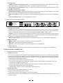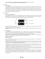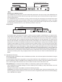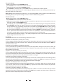
1
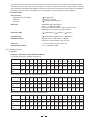
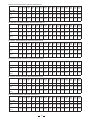
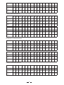
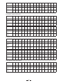
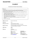
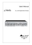
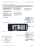
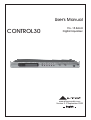
User's Manual
CONTROL30
15+15 Band
Digital Equalizer
R
LTO
www.altoproaudio.com
Version 2.3 September 2005
English
Fuse
SAFETY RELATED SYMBOLS
To prevent fire and damage to the product, use only
the recommended fuse type as indicated in this
manual. Do not short-circuit the fuse holder. Before
replacing the fuse, make sure that the product is
OFF and disconnected from the AC outlet.
CAUTION
RISK OF ELECTRIC SHOCK
DO NOT OPEN
This symbol, wherever used, alerts you to the presence of un-insulated and dangerous voltages within the product enclosure. These are voltages that
may be sufficient to constitute the risk of electric
shock or death.
Protective Ground
Before turning the product ON, make sure that it is
connected to Ground. This is to prevent the risk of
electric shock.
This symbol, wherever used, alerts you to important operating and maintenance instructions.
Please read.
Never cut internal or external Ground wires. Likewise,
never remove Ground wiring from the Protective
Ground Terminal.
Protective Ground Terminal
Operating Conditions
AC mains (Alternating Current)
Always install in accordance with the manufacturer's
instructions.
Hazardous Live Terminal
ON:
To avoid the risk of electric shock and damage, do
not subject this product to any liquid/rain or moisture.
Do not use this product when in close proximity to
water.
Denotes the product is turned on.
OFF: Denotes the product is turned off.
WARNING
Do not install this product near any direct heat source.
Describes precautions that should be observed to
prevent the possibility of death or injury to the user.
Do not block areas of ventilation. Failure to do so
could result in fire.
CAUTION
Keep product away from naked flames.
Describes precautions that should be observed to
prevent damage to the product.
IMPORTANT SAFETY INSTRUCTIONS
Read these instructions
Disposing of this product should not be
placed in municipal waste and should be
Separate collection.
Follow all instructions
Keep these instructions. Do not discard.
Heed all warnings.
WARNING
Only use attachments/accessories specified by the
manufacturer.
Power Supply
Ensure that the mains source voltage (AC outlet)
matches the voltage rating of the product. Failure
to do so could result in damage to the product and
possibly the user.
Power Cord and Plug
Do not tamper with the power cord or plug. These are
designed for your safety.
Unplug the product before electrical storms occur
and when unused for long periods of time to reduce
the risk of electric shock or fire.
Do not remove Ground connections!
External Connection
Protect the power cord and plug from any physical
stress to avoid risk of electric shock.
If the plug does not fit your AC outlet seek advice from
a qualified electrician.
Always use proper ready-made insulated mains
cabling (power cord). Failure to do so could result
in shock/death or fire. If in doubt, seek advice from
a registered electrician.
Do not place heavy objects on the power cord. This
could cause electric shock or fire.
Cleaning
When required, either blow off dust from the product
or use a dry cloth.
Do Not Remove Any Covers
Within the product are areas where high voltages
may present. To reduce the risk of electric shock do
not remove any covers unless the AC mains power
cord is removed.
Do not use any solvents such as Benzol or Alcohol.
For safety, keep product clean and free from dust.
Servicing
Covers should be removed by qualified service
personnel only.
No user serviceable parts inside.
Refer all servicing to qualified service personnel only.
Do not perform any servicing other than those instructions contained within the User's Manual.
1
PREFACE
Dear Customer:
Thanks for choosing
researches.
For our
ssion!
LTO CONTROL30 and thanks for choosing one of the results of
LTO AUDIO TEAM job and
LTO AUDIO TEAM, music and sound are more than a job...are first of all passion and let us say...our obse-
We have been designing professional audio products for a long time in cooperation with some of the major brands in
the world in the audio field.
The LTO line presents unparalleled analogue and digital products made by Musicians for Musicians in our R&D
Centers in Italy, Netherlands, United Kingdom and Taiwan. The core of our digital audio products is a sophisticated
DSP (Digital Sound Processor) and a large range of state of the art algorithms which have been developed by our
Software Team for the last 7 years.
Because we are convinced you are the most important member of LTO AUDIO TEAM and the one confirming the
quality of our job, we like to share with you our work and our dreams, paying attention to your suggestions and your
comments.
Following this idea we create our products and we will create the new ones! From our side, we guarantee you and we
will guarantee you also in future the best quality, the best fruits of our continuous researches and the best prices.
Our LTO CONTROL30 is the result of many hours of listening and tests involving common people, area experts,
musicians and technicians. The results of this effort is a DSP hi-performance equalizer that can be used in applications as musical performances, installation and sound reinforcement.
Besides we offer to you a number of factory EQ curves that we collected and transformed in presets now available in
our small, efficient and easy to use LTO CONTROL30.
Nothing else to add, but that we would like to thank all the people that made the LTO CONTROL30 a reality available to our customers, and thank our designers and all the LTO staff, people who make possible the realization of
products containing our idea of music and sound and are ready to support you, our customer, in the best way, conscious that you are our best richness.
Thank you very much.
LTO AUDIO TEAM
2
TABLE OF CONTENTS
1. INTRODUCTION .................................................................................................................................4
2. FEATURE LIST ....................................................................................................................................4
3. FRONT AND BACK PANELS DESCRIPTION ....................................................................................4
3.1. Control Panel (Front Panel)
a. Analog Levels
b. LEDs and Illuminated Power Switch
3.2. Analog Connections (Back Panel)
a. Analog Inputs/Outputs
b. MIDI Connectors
c. Power Connector
4. INSTALLATION & CONNECTION.......................................................................................................5
4.1. Power Up and Audio Connections
a. Audio Connections
b. Power Up Setting
4.2. Analog
a. Levels Setting
4.3. Installation
a. Mono Use of CONTROL30
b. Standard Use
c. Application Examples
-line Instrument
-Mixer
4.4. Operational Overview
5. PRESET FUNCTIONS DESCRIPTION...............................................................................................10
5.1. Eq Presets
a. Flat
b. Bass Debug
c. BBC Monitor
d. Brilliant
e. Hi Definition
f. Loudness
g. Percussion
h. Presence
i. Soft
j. Super Boost
k. Virtual Sub
l. Functional Data
5.2. Summary Tables
a. Presets
b. Block Diagrams
c. MIDI
6. TECHNICAL SPECIFICATIONS.........................................................................................................30
7. WARRANTY ......................................................................................................................................31
3
1. INTRODUCTION
Purchasing LTO CONTROL30, you purchase a very powerful equalizer, easy to use and contained in a very
efficient single unit rack package.
LTO CONTROL30 is equipped with two powerful and separate configurable DSP channels, allowing to use up to
30 parametric EQ filters in order to obtain the desired sound and timbre out of the musical signals. CONTROL30
is a versatile and very powerful machine...also don't forget to check our 60 factory presets, they will surprise you
for their quality, showing the versatility they give to LTO CONTROL30!
The 30 equalization DSP filters have been designed for a general purpose use and are very powerful when processing
full band input signals as CD sources or final results of mixing sessions. These algorithms are fully dual mono/stereo
algorithms and use very powerful high precision and symmetrical filters, designed for professional use, able to modify
the sound colour improving the overall sound quality without introducing any loss or distortion. All the algorithms are
based on classical algorithms for the audio signals filtering, modified and optimized. Thanks to the experience of LTO
AUDIO TEAM researchers.
2. FEATURE LIST
Robust and Compact Design
24/32 bits Digital Audio Processor
MPU Control
Variable Input / Output Gain
Illuminated Power Switch
Digital Saturation LED and Digital VU-Meters
Up to 17 dBu Line Level
Easy to Operate Front Panel Controls and Display
SMT Design for Greater Reliability
Optimized Signal Path to Provide Superior Sound
Manufactured Under QS9000, VDA6.1 Quality System
3. FRONT AND BACK PANELS DESCRIPTION
3.1. control Panel (Front Panel)
8
1
2
3
4
5
CLIP
CONTROL30
-6
-12
UP
R
LTO
-18
PROCESS
OVERFLOW
METER
IN/OUT
15+15 BAND
ON DIGITAL EQUALIZER
-24
OFF
-30
DOWN
ENTER
ESC
EDIT
UTIL
BYPASS
10
INPUT LEVEL
OFF
10
OFF
OUTPUT LEVEL
POWER
6
7
9
10
1. Digital Overflow
2. Meter In/Out LED
3. Edit LED
4. Utility LED
5. Bypass LED
6. VU-Meters
7. LCD Alphanumeric display 20x2
8. Up key
9. Down key
10. Enter key
11. Esc key
12. Edit key
13. Utility key
14. Bypass key
15. Analog Input volume
16. Analog Output gain
17. Power ON/OFF Switch
4
11
12
13
14
15
16
17
a. Analog Levels
- Analog Input Level Potentiometer (15): The input level control sets the main input gain, before the signal
reaches the input bus. It controls both the Input 1 and Input 2 levels simultaneously.
- Analog Output Level Potentiometer (16): The output level control sets the level going to the amplifier or mixer
from LTO CONTROL30.
b. LED and Illuminated Power Switch
- Digital Saturation LED (1): Displays the signal level coming into the input during normal operation. If the signal
level is too high, this LED will light and you will begin to hear distortion.
- Meter In/Out LED (2): These VU-meters show the input signal level [LED (2) OFF] or the output digital signal
level.
- Power On/Off Switch (17): Turns the apparatus on and off.
3.2. Analog Connections (Back Panel)
AC INPUT
95-120V /210-240V 60-50Hz
Rated Power Consumption 9W
PUSH
MODEL
TIP/PIN 2
RING/PIN 3
SLEEVE/PIN 1
FUSE:
A102
210-240V: T250mAL 250VAC
95-120V: 500mA 250VAC
REPLACE FUSE WITH CORRECT
TYPE ONLY
SERIAL
Apparaten skall anslutas till
jordat uttag nar den ansluts
till ett natverk
CODE
TIP/PIN 2
RING/PIN 3
SLEEVE/PIN 1
ON
OFF
OUTPUT
THRU
INPUT
OUTPUT2
OUTPUT1
MONO
PUSH
TIP/PIN 2
RING/PIN 3
SLEEVE/PIN 1
NEW
TIDE
NEW
3
2
TIDE
3
1
INPUT2(MONO)
2
1
INPUT1
MIDI
a. Analog Inputs/Outputs
- Inputs: These are 1/4"TRS and XLR balanced connectors which connect to sources such as the channel
inserts of mixing consoles. They may be used with nominal input levels from consumer to professional audio.
For Mono applications, use the Input 2 once set manually the MONO ON/OFF switch to ON.
- Outputs: These are 1/4"TRS and XLR balanced connectors which connect to devices such as the channel
inserts on a mixing console or power amplifier inputs. For Mono applications, use the Output1 and /or the
Output2 once set manually the MONO ON/OFF switch to ON.
- MONO ON/OFF Switch: This switch sets the operational mode, switch to ON for MONO applications.
b. MIDI Connectors
- MIDI In: 5-poles DIN connector for the MIDI input to the CONTROL30.
- MIDI Thru: 5-poles DIN connector for the MIDI thru.
- MIDI Out: 5-poles DIN connector for the MIDI output from the CONTROL30.
c. Power Connector
- Power Connector: This is an IEC 3-pole socket for connecting the AC power supply to the CONTROL30.
4. INSTALLATION & CONNECTION
4.1. Power Up and Audio Connections
a. Audio Connections
The connections between the CONTROL30 and the other audio devices have to be made using high quality
cables so to prevent bad performances of the CONTROL30 itself. So it should be good to use low-capacitance shielded cables with a flexible internal conductor. Connect the cables to the CONTROL30 properly
by observing the following precautions:
Do not bundle audio cables with AC power cords.
Do not place audio cables and CONTROL30 near sources of electromagnetic interference such as
transformers, monitors, computers, etc.
Always unplug cables by firmly grasping the body of the plug and pulling directly outward.
Do not place cables where they can be stepped on.
Avoid twisting a cable or having it make sharp, right angle turns.
b. Power Up Setting
Before turning on the CONTROL30's power, check if:
All connections have been made correctly.
The volume controls of the amplifier or mixer are turned down.
Insert the Power plug into the POWER input on the rear panel of the CONTROL30 and plug the power cord
into an AC outlet.
5
Turn on the power of the CONTROL30, pushing the ON/OFF button on the front panel.
Turn on the power of the amplifier/mixer, and adjust the volume.
4.2. Analog
a. Levels Setting
Proper setting of the input and output levels is crucial in order to achieve the maximum signal-to-noise ratio.
It is possible to say that it is usually best to set both input and output level controls at 3/4 or 75% of full. This
will decrease the possibility of overload distortion and keep the amount of background noise to a minimum.
If the VU-meter or the Digital Saturation LED on the CONTROL30 begin to clip (turn red), turn down the Input
level or decrease the volume of the source (instrument, mixer, etc.). If the output level is causing the mixer or
amp to distort, turn the Output Level down.
4.3. Installation
a. Mono Use of CONTROL30
The CONTROL30's Input2 can be used as MONO input when necessary setting in the proper way the switch
MONO ON/OFF on the back panel of CONTROL30 itself. When the MONO ON/OFF switch is manually set
to ON position, physically the Input2 will be routed also on the internal Input1 line.
Inputs
Outputs
Input 2
Output 1
Output 2
ON POSITION
Input 1
Input 2
Output 1
Output 2
OFF POSITION
When the MONO ON/OFF switch is set to OFF position, the Input2 is no more routed on the Input1 line and
CONTROL30 works in full stereo configuration.
When the input signal is mono, it has to be connected to the Input2 and the MONO ON/OFF switch must be
set to ON.
b. Standard Use
The CONTROL30 may be placed almost anywhere: on a table, on top of an amp, next to a mixing console. If it
will be on furniture, check the rubber feet provided to the bottom of the unit. Make sure to place the CONTROL30
away from other audio equipment that may induce fields and away from the signal wiring.
It is possible that CONTROL30 may pick up noise fields generated by other equipment such as large power
amplifiers; in this case, move the CONTROL30 until the noise goes away.
c. Application Examples
- line Instrument
When connecting audio cables and/or turning power on and off, make sure that all devices in your system have
their volume controls turned down.
CONTROL30 has four inputs (two 1/4" TRS inputs and two XLR balanced inputs) and four outputs (two 1/4" TRS
outputs and two XLR balanced outputs) allowing the CONTROL30 to be used in a classical Stereo In and Stereo
Out connection or in Mono configuration as described above.
MONO. Set manually the MONO ON/OFF switch to position ON. Connect one audio cable to the Input2 of
the CONTROL30 from a mono source, and one or two other audio cables from the Output1 and Output2 of the
CONTROL30 to a mono/stereo amplification system or one/two mixer inputs.
STEREO. Set manually the MONO ON/OFF switch to position OFF. Connect two audio cables to the Input1
and Input2 of the CONTROL30 from a stereo source, and two other audio cables from the Output1 and Output2
of the CONTROL30 to a stereo amplification system or two mixer inputs.
This connection scheme is suitable also for processing Hi-Fi stereo sources like CD players or recording decks.
To process the signal coming from low signal voltage devices such as Hi-Fi turntable cartridges or microphones,
please insert before CONTROL30 a suitable pre-amplifier (i.e. a RIAA stage for turntables, our MicTube for
microphones).
6
To Amplifier or Mixing Console
From Stereo Audio Source
Input 1
Output 1
Input 2
Output 2
CLIP
CONTROL30
-6
-12
R
LTO
-18
UP
PROCESS
OVERFLOW
METER
IN/OUT
DOWN
ENTER
ESC
ON
-24
OFF
-30
EDIT
UTIL
BYPASS
10
OFF
INPUT LEVEL
15+15 Band
Digital Equalizer
OFF
10
OUTPUT LEVEL
POWER
- Mixer
Interfacing to a Mixing Console
The CONTROL30 can accept mono or stereo sends at all system levels. The input circuitry of the CONTROL30 can
easily accept professional levels while having enough input and output gain to interface with the low signal levels of
home recording systems.
The CONTROL30 may be connected to a mixing console connecting the unit directly to the channel insert socket
of a single channel that is to be processed. Another way of interfacing the CONTROL30 to a mixer or recording
console would be in-line between the output of your mixing console and the input of a tape deck or power amplifier.
This last setup would be used only if you wanted to process the entire mix.
Using Inserts
Inserts
Input 1
Output 1
Input 2
MIXING CONSOLE
Output 2
CLIP
CONTROL30
-6
-12
R
LTO
-18
UP
PROCESS
OVERFLOW
METER
IN/OUT
DOWN
ENTER
ESC
ON
-24
OFF
-30
EDIT
UTIL
BYPASS
10
INPUT LEVEL
OFF
10
15+15 Band
Digital Equalizer
OFF
OUTPUT LEVEL
POWER
In the above figure it describes the situation in which you want to apply the CONTROL30 to a couple of channels arriving to a mixing console, in order to apply the desired dynamic process to single instrument's signals;
in this case you will have to use a mixer which features individual channel inserts. Insert jacks on the back
of a mixer provide a way of 'inserting' external processing equipment into the signal path. The insert occurs
after the input amplifier, and before the channel fader; essentially it is the same as connecting the source
(instrument or mic) into the CONTROL30 before the mixer's channel input. Usually, insert connections require
a special, stereo-splitting Y-cord to be connected, known as TRS connector. This connector has a stereo jack
which plugs into mixer's channel insert socket, and a couple of mono jacks (input and output) which will plug
into CONTROL30 via jack-XLR adapters. Fitting this kind of cabling will virtually insert into one mixer's channel the EQ process. Take good care in adjusting CONTROL30 input and output levels, in order to satisfy the
dynamics needs of both the processed channels. Do not use the CONTROL30 the effects send/return connections found on most mixers for effect modules, as they could lead to heavy frequency response alterations.
Improper level setting when using a digital processor is the most common cause of noise and distortion problems.
4.4. Operational Overview
Switching ON the CONTROL30, after an initialization procedure, the last stored preset will be loaded. Changes
not saved will be lost.
To load exactly the last preset configuration running before shutdown of the CONTROL30, it's necessary to store
these modifications using the STORE Function available into the UTILITY Menu. After the initialization procedure,
on the LCD will appear the first field of the UTILITY Menu and the UTILITY LED will turn ON.
Utility Button(13): To access the UTILITY Menu, it's necessary to push the UTILITY Button (13).
If the CONTROL30 is already working on UTILITY Menu (UTILITY LED (4) = ON), each further use of the
button will have no effect.
Using the UTILITY Menu is possible to access the following functions:
Load Preset: This function allows the loading of one of the 124 available presets, where the first 60 presets (1- 60)
are factory presets, and the presets from 61 to 124 are the user's configurable presets and all not initialized (Empty)
when CONTROL30 is shipped.
7
To Load a Preset:
Select "Load Preset" using UP/DOWN buttons.
Press ENTER button to access the further sub-menu.
Select the chosen preset using UP/DOWN buttons.
Press ENTER to load the preset or press ESC button if you decide not to load the preset.
Once terminated the sequence above, on the display will appear the name of the selected preset and the system will go back to the main menu.
Store Preset: This function allows the storing on one of the 60 available memory locations the modified (using
the Editing Menu) user's preset, starting from one of the 64 available factory presets.
To Store a Preset:
Select "Store Preset" using UP/DOWN buttons.
Press ENTER button to access the further sub menu.
Select the memory location (Empty or already occupied from a previous user's preset) where to store the
new user's preset using UP/DOWN buttons.
If you want to give up, press ESC to go back to the main menu without storing the new preset, otherwise,
press ENTER to store the new preset. The user can choose the identification name for the new preset
using 6 characters max. The blinking character will be modified using the UP/DOWN buttons. When choosing
th
the character, press ENTER to confirm and go to the next one. Pressing ESC before the 6 character, the
old name will be maintained as name of the new preset. Pressing ENTER as confirmation of the 6th character,
the new preset will be stored with the new name. There is no possibility to correct a confirmed character, if
necessary to change again the name, repeat the storing process from the beginning.
Once terminated the sequence above, on the display will appear the name of the new stored preset and the
system will go back to the main menu.
Equ Setup
This function allows the user to select the type of EQ to be used:
Graphical 2x15 Dual Mono (15 filters per channel)
This is a graphical EQ (fixed Q and frequencies) with independent settings for each channel. When this type
of EQ is selected, only a channel a time can be edited. To select the channel to be edited, click the EDIT key
and select Channel item.
Parametric 2x15 Dual Mono (15 filters per channel)
This is a parametric EQ (variable Q and frequencies) with independent settings for each channel. When this
type of EQ is selected, only a channel a time can be edited. To select the channel to be edited, click the EDIT
key and select Channel item.
Graphical 2x15 Stereo (15 filters per channel)
This is a graphical EQ (fixed Q and frequencies) in which both channels share the same settings. When this
type of EQ is selected, both channels are simultaneously edited. If the EDIT key is pressed and Channel item
is selected, the parameter shows LNK (linked) and cannot be changed.
Parametric 2x15 Stereo (15 filters per channel)
This is a parametric EQ (variable Q and frequencies) in which both channels share the same settings. When
this type of EQ is selected, both channels are simultaneously edited. If the EDIT key is pressed and Channel
item is selected, the parameter shows LNK (linked) and cannot be changed.
Graphical 1x30 Mono (30 filters / one channel)
This is a graphical EQ (fixed Q and frequencies) with 30 filters on one channel. When this type of EQ is selected,
only a channel works and can be edited. If the EDIT key is pressed and Channel item is selected, the parameter
shows LNK (linked) and cannot be changed.
Parametric 1x30 Mono (30 filters / one channel)
This is a parametric EQ (variable Q and frequencies) with 30 filters on one channel. When this type of EQ is
selected, only a channel works and can be edited. If the EDIT key is pressed and Channel item is selected, the
parameter shows LNK (linked) and cannot be changed.
8
To change EQ Type:
-Click Util key
-Select EQ Setup
-Press ENTER to access the sub-menu
-Select the EQ Type using UP/DOWN buttons
-Press ENTER to confirm
-The system asks confirmation of change: press ENTER to go on.
At this point the system loads a default FLAT preset of the same type of the selected EQ type.
To know what EQ type is currently loaded, click UTIL key, then select the item EQ Type using UP/DOWN keys.
Warning!
Both the Factory and the User presets are classified by the EQ types described above. When the user is in
the Load Preset function an identifier in the lower right corner of the display describes the EQ type the preset
belongs to:
G2M: Graphical 2x15 Dual Mono
P2M: Parametric 2x15 Dual Mono
G2S: Graphical 2x15 Stereo
P2S: Parametric 2x15 Stereo
G1M: Graphical 1x30 Mono
P1M: Parametric 1x30 Mono
Only a preset belonging to the currently selected EQ Type can be loaded. If the user tries ie. to load
a parametric preset on a graphical equalizer, the system will refuse to load it and the display will show:
Warning! This preset cannot be loaded
MIDI Setup: The MIDI SETUP utility allows the user to set up the CONTROL30 MIDI configuration.
The configurable MIDI parameters are:
MIDI Channel: Allows to define the MIDI CHANNEL to associate to the CONTROL30 when connected to
remote MIDI devices. When MIDI CHANNEL is set to OFF, the CONTROL30 will ignore MIDI commands
coming from external MIDI devices.
MIDI Output: When this function is set to ON, it is possible to ECHO on the MIDI output of the CONTROL30
all the incoming MIDI messages.
Output Attenuation: This control allows the digital output volume setting. This parameter is a system parameter and its modifications act on all the presets.
Bypass Button (14): Using this button is possible to bypass the process, sending to the CONTROL30 outputs exactly the input signals. This is a digital bypass and the input signal is anyway converted digitally
before being sent to the outputs. When the CONTROL30 is in this mode (Bypass LED (5) = ON), all the
buttons except the" bypass" button are disabled.
Up/Down Button (8/9): These buttons are used to navigate the menus and to modify the parameter values.
Enter/Esc Button (10/11): These buttons are used to access or to leave the menus or to confirm the parameter values.
Edit Button (12): This button allows the user to enter the EDIT Menu (the Edit LED(3) will be ON). When
entering the Edit Menu, the user will be able to access and modify all the parameters related to the process.
When the user modifies one parameter value, the LED (1) starts to blink to signal the update. The LED will
blink until the storing of the new modified preset in one of the 60 available locations.
VU-Meter: This function allows the user to use the VU-meters (6) to show the input signal level or the digital
output signal level.
LED Meter (2): This LED is ON when the VU-meters are showing the digital output level and is OFF when
the VU-meters are showing the analog signal input level.
9
5. PRESET FUNCTION DESCRIPTIONS
5.1. EQ Presets
a. Flat
This program allows the audio signal to cross the CONTROL30 unmodified.
b. Bass Debug
Bass debug is a program particularly suitable to clean recordings which have an exaggerate bass equalization in the
100 Hz area. This region of the audio spectrum is carefully cleaned and re-balanced by means of a slight boost in the
5 kHz range. The extreme octaves and the central one are left almost untouched. Some modern pop recordings need
a similar treatment.
c. BBC Monitor
This program is our homage to a legend. If you have available really full range loudspeaker system, enabling this preset will give you a certain idea of the sound of the famous near field monitors engineered by
BBC decades ago and still used by professionals and enthusiasts worldwide...Great for classic British pop
recordings.
10
d. Brilliant
This preset 'moves on' music and gives vitality to 'slow' recordings. The main EQs are centered in the 100 Hz,
1 kHz and 10 kHz area. The boost reaches almost 10 dB in the high end giving more definition to recordings
which are poor in high band energy. The low end is controlled down to 0 dB, while the high end is still slightly
boosted. Avoid using this programs with too brilliant or noisy recordings. Try it with modern symphonic music.
e. Hi Definition
Keyword is 'no compromise'. Selecting Hi definition you are giving your stereo system or recorder a well
characterized timbre; if you listen to this program with a linear system and a linear recording, you will judge
it 'nasty', but we aren't thinking to linear things when we make this EQ, just think to some bass-reflex loudspeakers, capable in emission, but confused by the abundance of bass frequencies and the lack of power
in the high end, or consider that a similar pre-emphasis could revitalise that sane-sounding but noisy analog
reel tape deck, and probably the hi-frequency emphasis we put in this program will be very useful to you.
f. Loudness
11
The classic 'loudness' filter was once present even in integrated stereo amplifiers, to give more power and
definition to sound. With modern day equipments, which need dynamic and linear performance, filters are
often not present to shorten the signal path and allow a cleaner electrical structure, but they are analog filters.
The CONTROL30 makes use of modern digital DSP techniques to recreate this useful filter (the loudness
curve improves the listening experience at low volumes and into noisy environments) without analog circuit
complexity. Ideal for clubs and public diffusion at low volumes.
g. Percussion
Four carefully selected boost peaks improve percussion instruments perception. The first peak is located at
100 Hz, the second at 250 Hz, the third at 6 kHz and the fourth at 15 kHz. This program may be used in various
kinds of music, giving often very good results and staying away from saturation, thanks to energy recover in the
low end of the spectrum.
h. Presence
When you need to underline voices and ambience, without cutting too much of the musical ensemble, 'Presence'
is a good choice. It moves forward voices and ambience without sacrificing the rest of the spectrum, thanks to
a very progressive EQ curve, peaked at 3500 Hz. Definitely try it if you like natural ambience recordings (live
in reverberating environments).
12
i. Soft
What is worse than a beautiful and super dynamic recording mistreated by a too brilliant and harsh mastering
and/or equalization? If you thought to certain black/disco music of the '70/'80, you are plain right. This EQ
will complement some great recordings by, say, Earth Wind & Fire as if it was tailored on. As a matter of fact,
it is.
j. Super Boost
A hot loudness program for modern music lovers. Good to revitalise old rock and pop tracks which are scarce
in dynamics and frequency extension, or to make some little loudspeaker systems that have good power
handling but not broad frequency extension seem bigger. It is also suited to re-balance recordings or diffusion
systems that tend to be too vocal-centered. As a loudness, Super-boost is able to greatly improve low volume
listening, especially in noisy areas.
k. Virtual Sub
13
Your ideal sound has lots of punch and impact? Your system is a bit shy on low ends, but otherwise linear?
Would you like more 'guts' out of a good pop disc? Try this, it could be the answer. On big systems with high
power handling and already well capable in the low end, this kind of reinforcement could be like an earthquake.
Definitely to try with game sound systems, but pay attention to power output and cone resistance.
l. Functional Data
User Interface
Alphanumeric LCD Display
Keyboard
VU meter
2 20 characters
7 user keys / 5 LEDs
2 6 LEDs (double function)
EQ Filters
Biquadratic Bell Filters type IV
Gain: +/- 15 dB step 0.5 dB
Frequency: 20Hz to 20kHz, minimum step 1/12 Oct
Bandwidth: 0.05 Oct to 3 Oct step 0.05 Oct
Parametric EQs
2
15 Dual Mono, 2
15 Stereo, 1
30 Mono
Graphical EQs
2
15 Dual Mono, 2
15 Stereo, 1
30 Mono
Band Pass Filters
Butterworth up to 2nd order (-12 dB/Oct)
Frequency: 20Hz to 20kHz, step 1/12 Oct
Delay line
0 - 510 ms step 2 ms (fine step 21 us)
Output digital volume
-15 / +12 dB step 0.5 dB
5.2. Summary tables
a. Presets
Graphical / Parametric 2 15 Dual Mono/Stereo
Flat: Preset 01/Preset 11/Preset 21/Preset 31
PEQ
1
PEQ
2
PEQ
3
PEQ
4
PEQ
5
PEQ
6
PEQ
7
PEQ
8
PEQ
9
PEQ
10
PEQ
11
PEQ
12
PEQ
13
PEQ
14
PEQ
15
Gain [dB]
0
0
0
0
0
0
0
0
0
0
0
0
0
0
0
Frequency
[Hz]
25
40
63
100
160
250
400
630
1000 1600 2500 4000 6300 10000 16000
Bandwidth
[Oct]
0.65
0.65
0.65
0.65
0.65
0.65
0.65
0.65
0.65
0.65
0.65
0.65
0.65
0.65
0.65
Bass Debug: Preset 02/Preset 12/Preset 22/Preset 32
PEQ
1
PEQ
2
PEQ
3
PEQ
4
PEQ
5
PEQ
6
PEQ
7
PEQ
8
PEQ
9
PEQ
10
PEQ
11
PEQ
12
PEQ
13
PEQ
14
PEQ
15
Gain [dB]
-0.5
0
-2.5
-3
-3
-1
0
0
0
0
2
3
3
2.5
0
Frequency
[Hz]
25
40
63
100
160
250
400
630
1000 1600 2500 4000 6300 10000 16000
Bandwidth
[Oct]
0.65
0.65
0.65
0.65
0.65
0.65
0.65
0.65
0.65
0.65
0.65
0.65
0.65
0.65
0.65
BBC Monitor: Preset 03/Preset 13/Preset 23/Preset 33
PEQ
1
PEQ
2
PEQ
3
PEQ
4
PEQ
5
PEQ
6
PEQ
7
PEQ
8
PEQ
9
PEQ
10
PEQ
11
PEQ
12
PEQ
13
PEQ
14
PEQ
15
Gain [dB]
-12
-3
-0.5
2
2.5
2
0
0
0
0
2
2.5
4
2
2.5
Frequency
[Hz]
25
40
63
100
160
250
400
630
1000 1600 2500 4000 6300 10000 16000
Bandwidth
[Oct]
0.65
0.65
0.65
0.65
0.65
0.65
0.65
0.65
0.65
14
0.65
0.65
0.65
0.65
0.65
0.65
Brilliant: Preset 04/Preset 14/Preset 24/Preset 34
Gain [dB]
PEQ
1
PEQ
2
PEQ
3
PEQ
4
PEQ
5
PEQ
6
PEQ
7
PEQ
8
PEQ
9
PEQ
10
PEQ
11
PEQ
12
PEQ
13
PEQ
14
PEQ
15
4
4
0
2
2
7.5
3
0
0
4
5
2.5
1
0
0
Frequency
[Hz]
25
40
63
100
160
250
400
630
1000 1600 2500 4000 6300 10000 16000
Bandwidth
[Oct]
0.65
0.65
0.65
0.65
0.65
0.65
0.65
0.65
0.65
0.65
0.65
0.65
0.65
0.65
0.65
Hi Definition: Preset 05/Preset 15/Preset 25/Preset 35
PEQ
1
PEQ
2
PEQ
3
PEQ
4
PEQ
5
PEQ
6
PEQ
7
PEQ
8
PEQ
9
PEQ
10
PEQ
11
PEQ
12
PEQ
13
PEQ
14
PEQ
15
0
0
0
0
0
0
0
0
0
2
3
1
4.5
11
1
Frequency
[Hz]
25
40
63
100
160
250
400
630
1000 1600 2500 4000 6300 10000 16000
Bandwidth
[Oct]
0.65
0.65
0.65
0.65
0.65
0.65
0.65
0.65
0.65
0.65
0.65
0.65
0.65
0.65
0.65
Gain [dB]
Loudness: Preset 06/Preset 16/Preset 26/Preset 36
Gain [dB]
PEQ
1
PEQ
2
PEQ
3
PEQ
4
PEQ
5
PEQ
6
PEQ
7
PEQ
8
PEQ
9
PEQ
10
PEQ
11
PEQ
12
PEQ
13
PEQ
14
PEQ
15
0
0
0
2
3
6.5
0.5
0
0
5.5
5
3
1
0
0
Frequency
[Hz]
25
40
63
100
160
250
400
630
1000 1600 2500 4000 6300 10000 16000
Bandwidth
[Oct]
0.65
0.65
0.65
0.65
0.65
0.65
0.65
0.65
0.65
0.65
0.65
0.65
0.65
0.65
0.65
Percussion: Preset 07/Preset 17/Preset 27/Preset 37
PEQ
1
PEQ
2
PEQ
3
PEQ
4
PEQ
5
PEQ
6
PEQ
7
PEQ
8
PEQ
9
PEQ
10
PEQ
11
PEQ
12
PEQ
13
PEQ
14
PEQ
15
-2.5
-0.5
-0.5
8
-0.5
7
1
0
0
0
0
2.5
7.5
-1
4.5
Frequency
[Hz]
25
40
63
100
160
250
400
630
1000 1600 2500 4000 6300 10000 16000
Bandwidth
[Oct]
0.65
0.65
0.65
0.65
0.65
0.65
0.65
0.65
0.65
0.65
0.65
0.65
0.65
0.65
0.65
Gain [dB]
Presence: Preset 08/Preset 18/Preset 28/Preset 38
PEQ
1
PEQ
2
PEQ
3
PEQ
4
PEQ
5
PEQ
6
PEQ
7
PEQ
8
PEQ
9
PEQ
10
PEQ
11
PEQ
12
PEQ
13
PEQ
14
PEQ
15
-2.5
-1
-1
-1
-1
0.5
0.5
0
1
3
4.5
5
3
0
-2.5
Frequency
[Hz]
25
40
63
100
160
250
400
630
1000 1600 2500 4000 6300 10000 16000
Bandwidth
[Oct]
0.65
0.65
0.65
0.65
0.65
0.65
0.65
0.65
0.65
0.65
0.65
0.65
0.65
0.65
0.65
Gain [dB]
Soft: Preset 09/Preset 19/Preset 29/Preset 39
Gain [dB]
PEQ
1
PEQ
2
PEQ
3
PEQ
4
PEQ
5
PEQ
6
PEQ
7
PEQ
8
PEQ
9
PEQ
10
PEQ
11
PEQ
12
PEQ
13
PEQ
14
PEQ
15
1
3
4.5
5
3
0
-2.5
-2.5
-1
-1
-1
-1
0.5
0.5
0
Frequency
[Hz]
25
40
63
100
160
250
400
630
1000 1600 2500 4000 6300 10000 16000
Bandwidth
[Oct]
0.65
0.65
0.65
0.65
0.65
0.65
0.65
0.65
0.65
15
0.65
0.65
0.65
0.65
0.65
0.65
Super Boost: Preset 10/Preset 20/Preset 30/Preset 40
PEQ
1
PEQ
2
PEQ
3
PEQ
4
PEQ
5
PEQ
6
PEQ
7
PEQ
8
PEQ
9
PEQ
10
PEQ
11
PEQ
12
PEQ
13
PEQ
14
PEQ
15
Gain [dB]
0
6
8
7
7
0
0
0
0
0
6
5.5
6
9
0
Frequency
[Hz]
25
40
63
100
160
250
400
630
1000 1600 2500 4000 6300 10000 16000
Bandwidth
[Oct]
0.65
0.65
0.65
0.65
0.65
0.65
0.65
0.65
0.65
0.65
0.65
0.65
0.65
0.65
0.65
Graphical / Parametric 1x30 Mono
Flat: Preset 41/Preset 51
PEQ
1
PEQ
2
PEQ
3
PEQ
4
PEQ
5
PEQ
6
PEQ
7
PEQ
8
PEQ
9
PEQ
10
PEQ
11
PEQ
12
PEQ
13
PEQ
14
PEQ
15
Gain [dB]
0
0
0
0
0
0
0
0
0
0
0
0
0
0
0
Frequency
[Hz]
20
25
31.5
40
50
63
80
100
125
160
200
250
315
400
500
Bandwidth
[Oct]
0.33
0.33
0.33
0.33
0.33
0.33
0.33
0.33
0.33
0.33
0.33
0.33
0.33
0.33
0.33
PEQ
16
PEQ
17
PEQ
18
PEQ
19
PEQ
20
PEQ
21
PEQ
22
PEQ
23
PEQ
24
PEQ
25
PEQ
26
PEQ
27
PEQ
28
PEQ
29
PEQ
30
0
0
0
0
0
0
0
0
0
0
0
0
0
0
0
Frequency
[Hz]
630
800
1000 1250 1600 2000 2500 3150 4000 5000 6300 8000 10000 12500 16000
Bandwidth
[Oct]
0.33
0.33
0.33
Gain [dB]
0.33
0.33
0.33
0.33
0.33
0.33
0.33
0.33
0.33
0.33
0.33
0.33
Bass Debug: Preset 42/Preset 52
PEQ
1
PEQ
2
PEQ
3
PEQ
4
PEQ
5
PEQ
6
PEQ
7
PEQ
8
PEQ
9
PEQ
10
PEQ
11
PEQ
12
PEQ
13
PEQ
14
PEQ
15
Gain [dB]
0
0
0
0
-4
-3
-2
-3
-2
0
0
0
0
0
0
Frequency
[Hz]
20
25
31.5
40
50
63
80
100
125
160
200
250
315
400
500
Bandwidth
[Oct]
0.33
0.33
0.33
0.33
0.33
0.33
0.33
0.33
0.33
0.33
0.33
0.33
0.33
0.33
0.33
PEQ
16
PEQ
17
PEQ
18
PEQ
19
PEQ
20
PEQ
21
PEQ
22
PEQ
23
PEQ
24
PEQ
25
PEQ
26
PEQ
27
PEQ
28
PEQ
29
PEQ
30
0
0
0
0
0
0
0
1.5
1.5
0.5
1.5
2.5
2
0
0
Frequency
[Hz]
630
800
1000 1250 1600 2000 2500 3150 4000 5000 6300 8000 10000 12500 16000
Bandwidth
[Oct]
0.33
0.33
0.33
Gain [dB]
0.33
0.33
0.33
0.33
0.33
0.33
0.33
0.33
0.33
0.33
0.33
0.33
BBC Monitor: Preset 43/Preset 53
PEQ
1
PEQ
2
PEQ
3
PEQ
4
PEQ
5
PEQ
6
PEQ
7
PEQ
8
PEQ
9
PEQ
10
PEQ
11
PEQ
12
PEQ
13
PEQ
14
PEQ
15
Gain [dB]
-7
-3
-2.5
-1.5
-1
0
1.5
3
2
2
2
0
0
0
0
Frequency
[Hz]
20
25
31.5
40
50
63
80
100
125
160
200
250
315
400
500
Bandwidth
[Oct]
0.33
0.33
0.33
0.33
0.33
0.33
0.33
0.33
0.33
0.33
0.33
0.33
0.33
0.33
0.33
16
PEQ
16
PEQ
17
PEQ
18
PEQ
19
PEQ
20
0
0
0
0
0
Frequency
[Hz]
630
800
1000 1250 1600 2000 2500 3150 4000 5000 6300 8000 10000 12500 16000
Bandwidth
[Oct]
0.33
0.33
0.33
Gain [dB]
PEQ
21
PEQ
22
1.5
2.5
PEQ
23
0
PEQ
24
1.5
PEQ
25
1
PEQ
26
PEQ
27
PEQ
28
2.5
3.5
1.5
PEQ
29
PEQ
30
1
0
0.33
0.33
0.33
0.33
0.33
0.33
0.33
0.33
0.33
0.33
0.33
0.33
Brilliant: Preset 44/Preset 54
PEQ
1
PEQ
2
PEQ
3
PEQ
4
PEQ
5
PEQ
6
PEQ
7
PEQ
8
PEQ
9
PEQ
10
PEQ
11
PEQ
12
PEQ
13
PEQ
14
PEQ
15
Gain [dB]
0.5
2
2
1.5
1
0
0
0
0
0
0
0
0
0
0
Frequency
[Hz]
20
25
31.5
40
50
63
80
100
125
160
200
250
315
400
500
Bandwidth
[Oct]
0.33
0.33
0.33
0.33
0.33
0.33
0.33
0.33
0.33
0.33
0.33
0.33
0.33
0.33
0.33
PEQ
16
PEQ
17
PEQ
18
PEQ
19
PEQ
20
PEQ
21
PEQ
22
PEQ
23
PEQ
24
PEQ
25
PEQ
26
PEQ
27
PEQ
28
PEQ
29
PEQ
30
0
0
0
2.5
0
2
2
0
2
2.5
6.5
3
4.5
3.5
0
Frequency
[Hz]
630
800
1000 1250 1600 2000 2500 3150 4000 5000 6300 8000 10000 12500 16000
Bandwidth
[Oct]
0.33
0.33
0.33
Gain [dB]
0.33
0.33
0.33
0.33
0.33
0.33
0.33
0.33
0.33
0.33
0.33
0.33
Hi Definition: Preset 45/Preset 55
PEQ
1
PEQ
2
PEQ
3
PEQ
4
PEQ
5
PEQ
6
PEQ
7
PEQ
8
PEQ
9
PEQ
10
PEQ
11
PEQ
12
PEQ
13
PEQ
14
PEQ
15
Gain [dB]
0.5
1
-0.5
0.5
1
0
0
0
0
0
0
0
0
0
0
Frequency
[Hz]
20
25
31.5
40
50
63
80
100
125
160
200
250
315
400
500
Bandwidth
[Oct]
0.33
0.33
0.33
0.33
0.33
0.33
0.33
0.33
0.33
0.33
0.33
0.33
0.33
0.33
0.33
PEQ
16
PEQ
17
PEQ
18
PEQ
19
PEQ
20
PEQ
21
PEQ
22
PEQ
23
PEQ
24
PEQ
25
PEQ
26
PEQ
27
PEQ
28
PEQ
29
PEQ
30
0
2.5
0
2
2
0
2
2.5
2
6
7
7
2
Gain [dB]
0
0
Frequency
[Hz]
630
800
1000 1250 1600 2000 2500 3150 4000 5000 6300 8000 10000 12500 16000
Bandwidth
[Oct]
0.33
0.33
0.33
0.33
0.33
0.33
0.33
0.33
0.33
0.33
0.33
0.33
0.33
0.33
0.33
Loudness: Preset 46/Preset 56
PEQ
1
PEQ
2
PEQ
3
PEQ
4
PEQ
5
PEQ
6
PEQ
7
PEQ
8
PEQ
9
PEQ
10
PEQ
11
PEQ
12
PEQ
13
PEQ
14
PEQ
15
Gain [dB]
0
0
0
0
0
3
4.5
4.5
2.5
2.5
0
0
0
0
0
Frequency
[Hz]
25
40
63
100
160
250
400
630
1000 1600 2500 4000 6300 10000 16000
Bandwidth
[Oct]
0.65
0.65
0.65
0.65
0.65
0.65
0.65
0.65
0.65
17
0.65
0.65
0.65
0.65
0.65
0.65
PEQ
16
PEQ
17
PEQ
18
PEQ
19
PEQ
20
PEQ
21
PEQ
22
PEQ
23
PEQ
24
PEQ
25
PEQ
26
PEQ
27
PEQ
28
PEQ
29
PEQ
30
0
0
0
0
0
0
0
0
0
0
2
2
4.5
7
0
Frequency
[Hz]
630
800
1000 1250 1600 2000 2500 3150 4000 5000 6300 8000 10000 12500 16000
Bandwidth
[Oct]
0.33
0.33
0.33
Gain [dB]
0.33
0.33
0.33
0.33
0.33
0.33
0.33
0.33
0.33
0.33
0.33
0.33
Percussion: Preset 47/Preset 57
PEQ
1
PEQ
2
PEQ
3
PEQ
4
PEQ
5
PEQ
6
PEQ
7
PEQ
8
PEQ
9
PEQ
10
PEQ
11
PEQ
12
PEQ
13
PEQ
14
PEQ
15
Gain [dB]
-1
-1
-1
-1.5
-0.5
-2
11
-0.5
-3
-2.5
-0.5
0
0
0
0
Frequency
[Hz]
20
25
31.5
40
50
63
80
100
125
160
200
250
315
400
500
Bandwidth
[Oct]
0.33
0.33
0.33
0.33
0.33
0.33
0.33
0.33
0.33
0.33
0.33
0.33
0.33
0.33
0.33
PEQ
16
PEQ
17
PEQ
18
PEQ
19
PEQ
20
PEQ
21
PEQ
22
PEQ
23
PEQ
24
PEQ
25
PEQ
26
PEQ
27
PEQ
28
PEQ
29
PEQ
30
0
0
0
0
0
0
0.5
0
6.5
0
0
0
6.5
0
0
Frequency
[Hz]
630
800
1000 1250 1600 2000 2500 3150 4000 5000 6300 8000 10000 12500 16000
Bandwidth
[Oct]
0.33
0.33
0.33
Gain [dB]
0.33
0.33
0.33
0.33
0.33
0.33
0.33
0.33
0.33
0.33
0.33
0.33
Presence: Preset 48/Preset 58
PEQ
1
PEQ
2
PEQ
3
PEQ
4
PEQ
5
PEQ
6
PEQ
7
PEQ
8
PEQ
9
PEQ
10
PEQ
11
PEQ
12
PEQ
13
PEQ
14
PEQ
15
Gain [dB]
-1
0
-0.5
-0.5
-1
0
-0.5
-0.5
-0.5
0
0
0
0
0
0
Frequency
[Hz]
20
25
31.5
40
50
63
80
100
125
160
200
250
315
400
500
Bandwidth
[Oct]
0.33
0.33
0.33
0.33
0.33
0.33
0.33
0.33
0.33
0.33
0.33
0.33
0.33
0.33
0.33
PEQ
16
PEQ
17
PEQ
18
PEQ
19
PEQ
20
PEQ
21
PEQ
22
PEQ
23
PEQ
24
PEQ
25
PEQ
26
PEQ
27
PEQ
28
PEQ
29
PEQ
30
Gain [dB]
-0.5
2
3
3
2.5
2.5
2.5
3.5
3
2
2
0.5
1
-1
-1
Frequency
[Hz]
630
800
1000 1250 1600 2000 2500 3150 4000 5000 6300 8000 10000 12500 16000
Bandwidth
[Oct]
0.33
0.33
0.33
0.33
0.33
0.33
0.33
0.33
0.33
0.33
0.33
0.33
0.33
0.33
0.33
Super Boost: Preset 49/Preset 59
PEQ
1
PEQ
2
PEQ
3
PEQ
4
PEQ
5
PEQ
6
PEQ
7
PEQ
8
PEQ
9
PEQ
10
PEQ
11
PEQ
12
PEQ
13
PEQ
14
PEQ
15
Gain [dB]
0
0
0
7
2.5
3
5.5
5.5
5.5
4.5
1
1
1.5
0
0
Frequency
[Hz]
20
25
31.5
40
50
63
80
100
125
160
200
250
315
400
500
Bandwidth
[Oct]
0.33
0.33
0.33
0.33
0.33
0.33
0.33
0.33
0.33
0.33
0.33
0.33
0.33
0.33
0.33
18
PEQ
16
PEQ
17
PEQ
18
PEQ
19
0
0
0
PEQ
20
PEQ
21
PEQ
22
PEQ
23
PEQ
24
PEQ
25
2.5
1.5
PEQ
26
PEQ
27
PEQ
28
PEQ
29
PEQ
30
4.5
1.5
Gain [dB]
0
Frequency
[Hz]
630
800
1000 1250 1600 2000 2500 3150 4000 5000 6300 8000 10000 12500 16000
Bandwidth
[Oct]
0.33
0.33
0.33
0.33
0
0
0
0
4
5
6
0.33
0.33
0.33
0.33
0.33
0.33
0.33
0.33
0.33
0.33
0.33
Virtual _ Sub: Preset 50/ Preset 60
PEQ
1
PEQ
2
PEQ
3
PEQ
4
PEQ
5
PEQ
6
PEQ
7
PEQ
8
PEQ
9
PEQ
10
PEQ
11
PEQ
12
PEQ
13
PEQ
14
PEQ
15
Gain [dB]
0
0
0
7
3.5
3
5.5
5.5
5.5
4.5
1
1
1.5
0
0
Frequency
[Hz]
20
25
31.5
40
50
63
80
100
125
160
200
250
315
400
500
Bandwidth
[Oct]
0.33
0.33
0.33
0.33
0.33
0.33
0.33
0.33
0.33
0.33
0.33
0.33
0.33
0.33
0.33
PEQ
16
PEQ
17
PEQ
18
PEQ
19
PEQ
20
PEQ
21
PEQ
22
PEQ
23
PEQ
24
PEQ
25
PEQ
26
PEQ
27
PEQ
28
PEQ
29
PEQ
30
0
0
0
0
0
0
0
0
0
0
0.5
0
0
Gain [dB]
0
0
Frequency
[Hz]
630
800
1000 1250 1600 2000 2500 3150 4000 5000 6300 8000 10000 12500 16000
Bandwidth
[Oct]
0.33
0.33
0.33
0.33
0.33
0.33
19
0.33
0.33
0.33
0.33
0.33
0.33
0.33
0.33
0.33
b. Block Diagrams
EQ Param. 2 15 Mono - EDIT MENU
Init
Up/Down
Enter/Esc
Channel
L/R
Equalizer
Enter/Esc
Enter/Esc
Enter/Esc
Par Filter 01
Par Filter 02
Gain
-15 / +15dB; 0.5dB
Frequency
20Hz/20KHz; 1/12 Oct
Bandwidth
0.05/3 Oct; 0.05 Oct
Gain
-15 / +15dB; 0.5dB
Frequency
20Hz/20KHz; 1/12 Oct
Bandwidth
0.05/3 Oct; 0.05 Oct
Up/Down
Up/Down
Par Filter 15
Band Pass
HP Filter
LP Filter
Delay
Gain
-15 / +15dB; 0.5dB
Frequency
20Hz/20KHz; 1/12 Oct
Bandwidth
0.05/3 Oct; 0.05 Oct
Frequency
20Hz/20KHz; 1/12 Oct
Slope
0, -6, -12 dB/Oct
Frequency
20Hz/20KHz; 1/12 Oct
Slope
0, -6, -12 dB/Oct
Delay Adj
0/510 ms; 2ms
Delay Fine
0/1998 us; 21us
-15 / +12dB; 0.5dB
Volume
20
EQ Param. 2 15 Stereo - EDIT MENU
Init
Enter/Esc
L+R (Locked)
Channel
Equalizer
Enter/Esc
Enter/Esc
Enter/Esc
Par Filter 01
Par Filter 02
Up/Down
Gain
-15 / +15dB; 0.5dB
Frequency
20Hz/20KHz; 1/12 Oct
Bandwidth
0.05/3 Oct; 0.05 Oct
Gain
-15 / +15dB; 0.5dB
Frequency
20Hz/20KHz; 1/12 Oct
Bandwidth
0.05/3 Oct; 0.05 Oct
Gain
-15 / +15dB; 0.5dB
Frequency
20Hz/20KHz; 1/12 Oct
Bandwidth
0.05/3 Oct; 0.05 Oct
Frequency
20Hz/20KHz; 1/12 Oct
Slope
0, -6, -12 dB/Oct
Frequency
20Hz/20KHz; 1/12 Oct
Slope
0, -6, -12 dB/Oct
Up/Down
Up/Down
Par Filter 15
Band Pass
HP Filter
LP Filter
Delay
Delay Adj
0/510 ms; 2ms
Delay Fine
0/1998 us; 21us
Volume
-15/+12dB; 0.5dB
21
EQ Param. 1 30 Mono - EDIT MENU
Init
Enter/Esc
Mono (Locked)
Channel
Equalizer
Enter/Esc
Enter/Esc
Enter/Esc
Par Filter 01
Par Filter 02
Up/Down
Gain
-15 / +15dB; 0.5dB
Frequency
20Hz/20KHz; 1/12 Oct
Bandwidth
0.05/3 Oct; 0.05 Oct
Gain
-15 / +15dB; 0.5dB
Frequency
20Hz/20KHz; 1/12 Oct
Bandwidth
0.05/3 Oct; 0.05 Oct
Gain
-15 / +15dB; 0.5dB
Frequency
20Hz/20KHz; 1/12 Oct
Bandwidth
0.05/3 Oct; 0.05 Oct
Frequency
20Hz/20KHz; 1/12 Oct
Slope
0, -6, -12 dB/Oct
Frequency
20Hz/20KHz; 1/12 Oct
Slope
0, -6, -12 dB/Oct
Up/Down
Up/Down
Par Filter 30
Band Pass
HP Filter
LP Filter
Delay
Delay Adj
0/510 ms; 2ms
Delay Fine
0/1998 us; 21us
Volume
-15 / +12dB; 0.5dB
22
EQ Graph. 1 30 Mono - EDIT MENU
Init
Enter/Esc
Channel
Mono (Locked)
Equalizer
Enter/Esc
Enter/Esc
Enter/Esc
Up/Down
Par Filter 01
Gain
-15 / +15dB; 0.5dB
Par Filter 02
Gain
-15 / +15dB; 0.5dB
Par Filter 30
Gain
-15 / +15dB; 0.5dB
HP Filter
Frequency
20Hz/20KHz; 1/12 Oct
Slope
0, -6, -12 dB/Oct
Frequency
20Hz/20KHz; 1/12 Oct
Slope
0, -6, -12 dB/Oct
Up/Down
Up/Down
Band Pass
LP Filter
Delay
Delay Adj
0/510 ms; 2ms
Delay Fine
0/1998 us; 21us
Volume
-15 / +12dB; 0.5dB
23
EQ Graph. 2 15 Stereo - EDIT MENU
Init
Enter/Esc
L+R (Locked)
Channel
Equalizer
Enter/Esc
Enter/Esc
Enter/Esc
Up/Down
Par Filter 01
Gain
-15 / +15dB; 0.5dB
Par Filter 02
Gain
-15 / +15dB; 0.5dB
Par Filter 15
Gain
-15 / +15dB; 0.5dB
HP Filter
Frequency
20Hz/20KHz;1/12 Oct
Up/Down
Up/Down
Band Pass
LP Filter
Delay
Slope
0, -6, -12 dB/Oct
Frequency
20Hz/20KHz; 1/12 Oct
Slope
0, -6, -12 dB/Oct
Delay Adj
0/510 ms; 2ms
Delay Fine
0/1998 us; 21us
Volume
-15 / +12dB; 0.5dB
24
EQ Graph. 2 15 Mono - EDIT MENU
Init
Up/Down
Enter/Esc
L/R
Channel
Equalizer
Enter/Esc
Enter/Esc
Enter/Esc
Up/Down
Par Filter 01
Gain
-15 / +15dB; 0.5dB
Par Filter 02
Gain
-15 / +15dB; 0.5dB
Par Filter 15
Gain
-15 / +15dB; 0.5dB
HP Filter
Frequency
20Hz/20KHz; 1/12 Oct
Slope
0, -6, -12 dB/Oct
Frequency
20Hz/20KHz; 1/12 Oct
Slope
0, -6, -12 dB/Oct
Up/Down
Up/Down
Band Pass
LP Filter
Delay
Delay Adj
0/510 ms; 2ms
Delay Fine
0/1998 us; 21us
Volume
-15 / +12dB; 0.5dB
25
Utility Menu
Up/Down
Enter/Esc
Preset 1,...,60 Factory
Preset 61,...,124 User
Load Preset
Up/Down
Store Preset
Up/Down
Enter
Enter/Esc
Preset 61,...,124
Edit Name (Char n 1)
Enter
Esc
Up/Down
Edit Name (Char n 2)
Enter
Up/Down
Esc
Edit Name (Char n 3)
Up/Down
Enter
Up/Down
Enter/Esc
Edit Name (Char n 6)
Up/Down
Enter/Esc
G2x15M, P2x15M, G2x15St,
P2x15St, G1x30M, P1x30M
Equ Setup
Up/Down
Enter/Esc
Enter/Esc
MIDI Setup
Channel
Up/Down
OFF,1,2,...,16,Omni
Up/Down
Output
Equ Flat
Enter
Up/Down
OFF / ON
All Filter Gain = 0dB
Up/Down
Enter/Esc
VU-Meter
(Input Signal) / (Output Signal)
Note:
A preset is loaded only if it's of the same type of the EQ currently active (Equ Setup Function).
26
Dual Mono 2
15 Bands Graphic / Parametric EQ Block Diagram
Volume
In L
Filt 01
Filt 02
Filt 15
High P
Low P
Delay
Out L
In R
Filt 01
Filt 02
Filt 15
High P
Low P
Delay
Out R
Mono 1
30 Bands Graphic / Parametric EQ Block Diagram
Volume
Volume
Filt 01
In
Stereo 2
Filt 02
High P
Filt 30
Low P
Delay
Out
15 Bands Graphic / Parametric EQ Block Diagram
Volume
InL
Filt 01
Filt 02
Filt 15
High P
Low P
Out L
Delay
InR
Out R
c. MIDI
st
MIDI 1 Byte - CONTROL CHANGE
Standard MIDI (Program Change, Control Change)
Program Change
1. If the system is in Bypass (Bypass LED = ON) whatever preset change request is ignored.
2. If the system is configured as i.e.G2 15M and a request to load a different EQ type preset arrives (i.e. P1
30M), the request is ignored.
3. A request to load an un-initial preset location (Preset User) is ignored.
4. User presets created for a type of EQ can not be loaded on another type. It's up to the user to create an
unambiguous list of presets.
5. If the system is disconnected from the MIDI network, it keeps the last loaded preset. If the system is turned
off and on, it will start with the last loaded preset, losing the information about editing done with control change.
It is advisable the use of a sequencer.
st
MIDI 1 Byte - PROGRAM CHANGE
MIDI 2nd Byte 0,...,127
(Min. Time Between Changes: 6 seconds )
MIDI 2nd Byte
Preset
0,...,9
Preset 1,...,10
Preset Custom - type G2
15M
10,...,19
Preset 11,...,20
Preset Custom - type P2
15M
20,...,29
Preset 21,...,30
Preset Custom - type G2
15S
30,...,39
Preset 31,...,40
Preset Custom - type P2
15S
40,...,49
Preset 41,...,50
Preset Custom - type G1
30M
50,...,59
Preset 51,...,60
Preset Custom - type P1
30M
60,...,123
Preset 61,...,124
27
Legend
Preset User
Control Change (Max. Frequency of Changes: 120 BPM)
MIDI commands will be executed from control30 only, if the status of the device is on the "Top Ring" or utility
menu and if the MIDI channel is set properly.
1. System executes MIDI commands also when in bypass.
2. Control 0 00 (Bank Set)
Possible values are 0, 1,...,5. Given cases:
a. G2 15M, P2x15M
Bank = 0, 2, 4 selects channel 2 (Right) and bank = 0, 1, 2
Bank = 1, 3, 5 selects channel 1 (Left) and bank = 0, 1, 2
b. G2 15S, P2 15S
Bank = 0, 2, 4 selects channel 1 & 2 (Left & Right) and bank = 0,1,2
Bank = 1, 3, 5 selects channel 1 & 2 (Left & Right) and bank = 0,1,2
c. G1 30, P1 30
Bank = 0, 2, 4 selects channel 2 (Right) and bank = 0, 1, 2 of EQ parametric filters 1,...,15
Bank = 1, 3, 5 selects channel 2 (Right) and bank = 0, 1, 2 of EQ parametric filters 16,...,30
3. Control 0 03 (Select Eq type) (Min. Time Between Changes: 6 seconds )
Possible values are 0, 1,...,5. Given cases:
a. G2 15M = 0, P2 15M = 1, G2 15S = 2, P2 15S = 3, G1 30 = 4, P1 30 = 5
Each change of Eq type the system loads a default preset for the EQ type.
4. Control 0 07 (Volume)
Possible values are 0, 1,...,54 corresponding to -15dB, -14.5dB,...,+12dB (step = 0.5dB)
5. Control 0 0E (Delay Adj)
Possible values are 0, 1,...,127 corresponding to 0ms, 4ms,...,508ms (step = 4ms)
6. Control 0 0F ( Delay Fine)
Possible values are 0, 1,...,95 corresponding to 0us, 21us,...,1998us (step = 21us)
7. Control 0 10 (Equalizer/Bypass)
Possible values are 0 and 1 corresponding to Equalizer = 0, Bypass = 1. Passing from Equalizer -> bypass
8. Control 0
11 (Filter Gain/Freq/Q)
9. Control 0
12 ( Filter Gain/Freq/Q)
10. Control 0
13 ( Filter Gain/Freq/Q)
11. Control 0
14 ( Filter Gain/Freq/Q)
12. Control 0
15 ( Filter Gain/Freq/Q)
13. Control 0
16 ( Filter Gain/Freq/Q)
14. Control 0
17 ( Filter Gain/Freq/Q)
15. Control 0
18 ( Filter Gain/Freq/Q)
16. Control 0
19 ( Filter Gain/Freq/Q)
17. Control 0
1A (Filter Gain/Freq/Q)
18. Control 0
1B (Filter Gain/Freq/Q)
19. Control 0
1C (Filter Gain/Freq/Q)
20. Control 0
1D (Filter Gain/Freq/Q)
21. Control 0
1E (Filter Gain/Freq/Q)
22. Control 0 1F (Filter Gain/Freq/Q)
a. G2 15M
Bank = 0, 2, 4 selects Gain, possible values are 0, 60; -15, +15dB step = 0.5dB Channel 2
Bank = 1, 3, 5 selects Gain, possible values are 0, 60; -15, +15dB step = 0.5dB Channel 1
28
b. P2 15M
Bank = 0 selects Gain, possible values are 0, 60; -15, +15dB step = 0.5dB Channel 2
Bank = 1 selects Gain, possible values are 0, 60; -15, +15dB step = 0.5dB Channel 1
Bank = 2 selects Gain, possible values are 0, 120; 20Hz,...,20KHz step = 1/12 Oct Channel 2
Bank = 3 selects Gain, possible values are 0, 120; 20Hz,...,20KHz step = 1/12 Oct Channel 1
Bank = 4 selects BandWidth, possible values are 0, 59; 0.05,...,3 Oct step = 0.05 Oct Channel 2
Bank = 5 selects BandWidth, possible values are 0, 59; 0.05,...,3 Oct step = 0.05 Oct Channel 1
c. G2 15S
Bank = 0, 1, 2, 3, 4, 5 selects Gain, possible values are 0, 60; -15, +15dB step = 0.5dB Channel 1 & 2
d. P2 15S
Bank = 0, 1 selects Gain, possible values are 0, 60; -15,+15dB step = 0.5dB Channel 1 & 2
Bank = 2, 3 selects Freq, possible values are 0, 120; 20Hz,...,20KHz step = 1/12 Oct Channel 1 & 2
Bank = 4, 5 sel. BandWidth, values 0, 59; 0.05,...,3 Oct step = 0.05 Oct Channel 1 & 2
e. G1 30M
Bank = 0, 2, 4 sel. Gain of first 15 filters, values are 0, 60; -15, +15dB step = 0.5dB Channel 2
Bank = 1, 3, 5 sel. Gain of the following15 filters, values are 0, 60; -15, +15dB step = 0.5dB Channel 2
f. P1 30M
Bank = 0 sel. Gain of first 15 filters, possible values are 0, 60; -15, +15dB step = 0.5dB Channel 2
Bank = 1 sel. Gain of the following 15 filters, values are 0, 60; -15, +15dB step = 0.5dB Channel 2
Bank = 2 sel. Freq. of first 15 filters, possible values are 0, 120; 20Hz,...,20KHz step = 1/12 Oct Channel 2
Bank = 3 sel. Freq. of the following 15 filters, values are 0, 60, 0, 120; 20Hz,...,20KHz step = 1/12 Oct Channel 2
Bank = 4 sel. BandWidth first 15 filters, values 0, 59; 0.05,...,3 Oct step = 0.05 Oct Channel 2
Bank = 5 sel. BandWidth following 15 filters, values 0, 59; 0.05,...,3 Oct step = 0.05 Oct Channel 2
23. Control 0 50 (HP Freq)
values 0,...,120 giving HP freq: 20Hz,...,20KHz step = 1/12 Oct
24. Control 0 51 (HP Slope)
values 0,1,2 giving: bypass filter, -6dB/Oct, -12dB/Oct
25. Control 0 52 (LP Freq)
values 0,...,120 giving HP freq: 20Hz,...,20KHz step = 1/12Oct
26. Control 0 53 (LP Slope)
values 0, 1, 2 giving: bypass filter, -6dB/Oct, -12dB/Oct
Command Sequence for MIDI standard control
1. Preset change:
a. Make sure the system is not bypassed.
(Control Change: command = 0 10 value = 0)
b. Make sure the preset is of the same type as current EQ type.
(Control Change: command = 0 03 val = 0,...,5)
c. Be sure you load the preset on the correct channel.
(Control Change: command = 0 00 val = 0,...,5)
d. Load preset
Program Change: val = 0,...,127)
2. Parameter Change:
a. Make sure the system is not bypassed.
(Control Change: command = 0 10 value = 0)
b. Issue the chosen command, keeping present to work on the right bank.
(Control Change: command = 0 00 val = 0,...,5)
c. Issue Control Change: command/value
29
6. TECHNICAL SPECIFICATIONS
Analog Input Section
Analog variable gain, 2 XLR-F electronically balanced
Inputs
Input Impedance
Max. input Level
Sensitivity
44 kOhms
15 dBu (4.4V RMS)
-22 dBu (63mV RMS)
Analog Output Section
Analog variable gain, 2 XLR-M electronically balanced
Outputs
Output Impedance
Max. output Level
<150 Ohms
17 dBu on 600 Ohms (5.5V RMS)
Digital / Analog Interface
Amplitude Response
Signal to Noise Ratio
Digital
THD+N
Group Delay
Sampling Frequency
Conversion
Processor Speed
20 Hz - 20 kHz + 0.2 / - 2.5 dB
90 dB (A wtg. / 20 Hz-20kHz)
0.03 % @ 1kHz -6 dB (VU-meter level)
700 s
46.875 kHz
1 bit Sigma-Delta
DSP Resolution
Control
12 MIPs
24 32bits
Microprocessor
Connections
Sockets
Mode
Input/Output/Thru
5-poles DIN (female)
Photo-coupled
Connector Type
Type
Mains Supply
Power Rating
3-pole IEC, grounded
Servo controlled, stabilized
95-120V /210-240V ,60-50Hz
numeric LCD Display
Keyboard
VU meter
2 20 characters
7 user keys / 5 LEDs
2 6 LEDs
Size
Dimensions
Net Weight
Standard 19'' rack mounting
483 (W) 232.5 ( D) 44 (H)mm (19'' 9.3'' 1.7'')
3.8 Kg (8.38lb)
MIDI Section
Power Supply
9W
User Interface
Physical
30
7. WARRANTY
1. WARRANTY REGISTRATION CARD
To obtain Warranty Service, the buyer should first fill out and return the enclosed Warranty Registration Card within
10 days of the Purchase Date.
All the information presented in this Warranty Registration Card gives the manufacturer a better understanding of
the sales status, so as to purport a more effective and efficient after-sales warranty service.
Please fill out all the information carefully and genuinely, miswriting or absence of this card will void your warranty
service.
2. RETURN NOTICE
2.1 In case of return for any warranty service, please make sure that the product is well packed in its original shipping
carton, and it can protect your unit from any other extra damage.
2.2 Please provide a copy of your sales receipt or other proof of purchase with the returned machine, and give detail
information about your return address and contact telephone number.
2.3 A brief description of the defect will be appreciated.
2.4 Please prepay all the costs involved in the return shipping, handling and insurance.
3. TERMS AND CONDITIONS
3.1
LTO warrants that this product will be free from any defects in materials and/or workmanship for a period
of 1 year from the purchase date if you have completed the Warranty Registration Card in time.
3.2 The warranty service is only available to the original consumer, who purchased this product directly from the
retail dealer, and it can not be transferred.
3.3 During the warranty service, LTO may repair or replace this product at its own option at no charge to you for
parts or for labor in accordance with the right side of this limited warranty.
3.4 This warranty does not apply to the damages to this product that occurred as the following conditions:
Instead of operating in accordance with the user's manual thoroughly, any abuse or misuse of this product.
Normal tear and wear.
The product has been altered or modified in any way.
Damage which may have been caused either directly or indirectly by another product / force / etc.
Abnormal service or repairing by anyone other than the qualified personnel or technician.
And in such cases, all the expenses will be charged to the buyer.
3.5 In no event shall LTO be liable for any incidental or consequential damages. Some states do not allow the exclusion or limitation of incidental or consequential damages, so the above exclusion or limitation may not apply to you.
3.6 This warranty gives you the specific rights, and these rights are compatible with the state laws, you may also
have other statutory rights that may vary from state to state.
31
SEIKAKU TECHNICAL GROUP LIMITED
No. 1, Lane 17, Sec. 2, Han Shi West Road, Taichung 40151 Taiwan
http://www.altoproaudio.com Tel: 886-4-22313737
email: [email protected] Fax: 886-4-22346757
All rights reserved to ALTO. All features and content might be changed
without prior notice. Any photocopy, translation, or reproduction of part of this
manual without written permission is forbidden. Copyright c 2005 SEIKAKU GROUP
NF 00865 -2.3