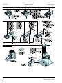
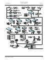
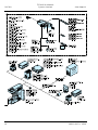
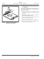
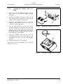
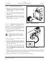
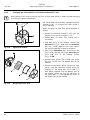
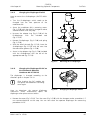
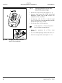
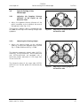
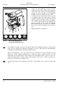
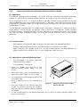
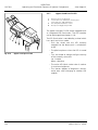
1
Microscope for Routine and Entry-Level Research
Operating Manual
Axio Scope.A1
Carl Zeiss
Copyright / Trademark
Axio Scope.A1
A thorough knowledge of these instructions is mandatory in order to operate the machine. Please
familiarize yourself with the content and follow the safety instructions by all means.
We reserve the right to make changes in the interest of further technical development. The manual is not
subject to updating.
©
Passing on and reproduction of this document, utilization and notice of its content are not
permitted unless explicitly allowed. Noncompliance is bound to indemnity.
All rights reserved, including rights created by patent grant or registration of a utility model or design.
Brands and names indicated in this manual may be trademarks of other companies. These brands and
names are mentioned only for information and do not express any approval or recommendation by us.
Carl Zeiss MicroImaging GmbH cannot assume any liability for the performance or the use of these
brands.
Published by:
Carl Zeiss MicroImaging GmbH
PO Box 4041, D - 37030 Goettingen
Telephone: +49 551 5060 660
Telefax:
+49 551 5060 464
E-mail:
[email protected]
www.zeiss.de
Number of the manual: M60-2-0007 e
Issue date: Version 6 – 13-05-2008
2
M60-2-0007 e 05/08
Axio Scope.A1
Content / Figures
Carl Zeiss
CONTENT
Page
1
INTRODUCTION ................................................................................................... 9
1.1
Safety Guidelines ............................................................................................................ 9
1.2
Warranty........................................................................................................................ 14
1.3
Stand Variants............................................................................................................... 15
1.4
Interface Diagram ......................................................................................................... 17
1.5
Summary of the Controls and Functional Elements................................................... 19
2
TECHNICAL MANUAL ........................................................................................ 21
2.1
Intended Use ................................................................................................................. 21
2.2
Systems Overview ........................................................................................................ 22
2.3
Technical Data ............................................................................................................... 27
3
STARTUP ............................................................................................................ 29
3.1
3.1.1
3.1.2
3.1.3
3.1.4
3.1.5
3.1.6
3.1.7
3.1.8
3.1.9
3.1.10
3.1.11
3.1.12
3.1.13
3.1.14
3.1.15
3.1.16
3.1.17
3.1.18
3.1.19
Mounting the Standard Components ......................................................................... 29
Unpacking and Mounting the Microscope Stand.............................................................. 29
Mounting the Upper Stand Part on the Stand Column ..................................................... 30
Mounting the Binocular Tube / Photo Tube ...................................................................... 31
Inserting Eyepieces or an Auxiliary Microscope ................................................................. 31
Mounting Objectives........................................................................................................ 33
Installing and Uninstalling "Push&Click" Modules in the Reflector Insert .......................... 34
Mounting the Reflector Insert .......................................................................................... 35
Mounting the Mechanical Stage ...................................................................................... 36
Mechanical Stages with Friction Adjustment .................................................................... 39
Mounting the LED Illuminator for Transmitted Light ......................................................... 41
Mounting the Condenser Carrier ..................................................................................... 42
Mounting the Condenser................................................................................................. 43
Mounting the Stage Carrier ............................................................................................. 44
Inserting the Halogen Lamp 12 V, 50 W........................................................................... 45
Halogen Lamp HAL 100 ................................................................................................... 46
Inserting the Adjustment Aid into the Upper Stand Part FL/HBO ....................................... 49
HBO 50 Illuminator .......................................................................................................... 49
HBO 100 Illuminator ........................................................................................................ 52
Illumination System Colibri and External Illumination Fixture HXP 120 .............................. 53
3.2
3.2.1
3.2.2
3.2.3
Connection of the Power Supply................................................................................. 54
Lower Stand Part for LED and HAL 50 Illumination............................................................. 54
Lower Stand Part for HAL 100 Illumination....................................................................... 54
Upper Stand Part for HAL 100/HBO, FL/HBO, FL-LED ........................................................ 55
9
9
9
9
1
1
1
1
1
1
1
1
1
1
1
1
1
1
1
1
1
1
1
1
1
1
1
1
1
1
1
M60-2-0007 e 05/08
1
1
1
1
3
Carl Zeiss
Content / Figures
Axio Scope.A1
3.3
Switching the Microscope and its Separate Illumination Fixtures on and off ......... 55
3.4
3.4.1
3.4.2
3.4.3
3.4.4
3.4.5
3.4.6
3.4.7
3.4.8
3.4.9
3.4.10
3.4.11
3.4.12
3.4.13
Mounting Optional Components ................................................................................ 56
Changing the Upper Stand Part and Inserting a Centerpiece for Larger Specimens ........... 56
Mounting the Intermediate Plate for Analyzer Slider......................................................... 57
Mounting the Tube Lens Turret........................................................................................ 57
Mounting the Magnification Changer.............................................................................. 58
Changing the Filters in the Reflector Module FL P&C........................................................ 58
Changing the Color Splitter in the Reflector Module FL P&C ............................................ 60
Mounting the Polarizer D or the Filter Holder ................................................................... 61
Mounting and Centering the Overview Fixture ................................................................. 62
Changing the LED Module in the Upper Stand Part FL-LED............................................... 63
Inserting a Modulator Disk in the Condenser 0.9/1.25 H .................................................. 64
Changing the Diaphragm PlasDIC .................................................................................... 65
Changing the Diaphragm Ph-DIC on the Achromatic-Aplanatic Condenser
0.9 H D Ph DIC ................................................................................................................ 65
Changing the Filter in the Filter Wheel Transmitted Light ................................................. 66
3.5
3.5.1
3.5.2
3.5.3
Default Setting of the Microscope .............................................................................. 67
Adjusting the Eyepiece Distance (Distance of the Pupils) on the Binocular Tube .................. 67
Adjusting the Viewing Height .......................................................................................... 67
Correction of Vision Defects with the Eyepiece Graticules ................................................ 68
4
OPERATION ....................................................................................................... 69
4.1
4.1.1
4.1.2
4.1.3
4.1.4
4.1.5
4.1.6
4.1.7
4.1.8
4.1.9
4.1.10
4.1.11
4.1.12
Illumination and Contrasting Method ........................................................................ 69
Adjusting the Transmitted Light/Bright-Field According to KÖHLER .................................. 69
Adjusting the Transmitted Light/Dark-Field According to KÖHLER .................................... 72
Adjusting the Transmitted Light/Phase-Contrast ............................................................... 74
Adjusting the Transmitted Light/Differential Interference Contrast (DIC) ........................... 76
Adjusting PlasDIC-Contrast in Transmitted Light .............................................................. 78
Adjusting Transmitted Light/Polarization .......................................................................... 79
Adjusting the Reflected Light/Bright-Field According to KÖHLER ...................................... 83
Adjusting the Reflected Light/Dark-Field........................................................................... 86
Adjusting Reflected Light DIC and Reflected Light C-DIC.................................................. 87
Adjusting Reflected Light TIC ........................................................................................... 88
Adjusting Reflected Light Polarization – Proof of Bireflexion and Reflexion pleochroism.... 91
Adjusting Reflected Light Fluorescence ............................................................................ 93
4.2
4.2.1
4.2.2
4.2.3
4.2.4
4.2.5
4.2.6
4.2.7
4.2.8
Operating and Functional Elements of Optional Components ................................. 95
Lower Stand Part for LED Transmitted Light Illumination .................................................. 95
Lower Stand Part with HAL 50 Illumination ...................................................................... 96
Lower Stand Part for HAL 100 Illumination ...................................................................... 97
Stand Column Vario 380 mm or 560 mm with Gear Box ................................................. 98
Upper Stand Part Transmitted Light ................................................................................. 99
Upper Stand Part FL/HBO ................................................................................................. 99
Upper Stand Part FL-LED ................................................................................................ 100
Upper Stand Part HAL 100/HBO..................................................................................... 101
1
1
1
1
1
1
1
1
1
1
1
1
1
1
4
1
1
1
1
1
1
1
1
1
1
1
1
1
1
1
1
1
1
1
1
1
1
1
1
1
1
1
1
M60-2-0007 e 05/08
Axio Scope.A1
Content / Figures
Carl Zeiss
4.2.9
4.2.10
4.2.11
4.2.12
Upper Stand Part HAL 100/HBO DIC .............................................................................. 101
Sideport ISCP T60N Left ................................................................................................. 102
Reflector Slider 2-fold .................................................................................................... 103
Reflector Turret 4-fold or 6-fold ..................................................................................... 103
5
MAINTENANCE, CHANGING OF FUSES AND SERVICE ................................... 109
5.1
Maintenance................................................................................................................ 109
5.2
5.2.1
5.2.2
Technical Service ......................................................................................................... 110
Check-Up ...................................................................................................................... 110
Changing the Fuses ....................................................................................................... 110
5.3
Trouble Shooting ........................................................................................................ 111
5.4
Service.......................................................................................................................... 114
6
ANNEX ............................................................................................................. 115
6.1
List of Abbreviations .................................................................................................. 115
6.2
Subject Index............................................................................................................... 117
6.3
Property Rights ........................................................................................................... 121
1
1
1
1
1
1
1
1
1
1
1
1
1
1
M60-2-0007 e 05/08
1
5
Carl Zeiss
Content / Figures
Axio Scope.A1
FIGURES
Fig. 1-1
Fig. 1-2
Fig. 1-3
0
1H
2H
Caution sign on lower stand part for HAL 100- and HAL 50-illumination............................. 13
Caution sign on upper stand part FL-LED............................................................................. 13
Interface diagram (upper stand part FL/HBO and lower stand part with
HAL 50 illumination) ........................................................................................................... 18
Summary of the controls and functional elements ............................................................... 20
Setting up the microscope................................................................................................... 29
Mounting the upper stand part on the stand column .......................................................... 30
Mounting the binocular tube .............................................................................................. 31
Inserting eyepieces .............................................................................................................. 31
Inserting an eyepiece graticule ............................................................................................ 32
Mounting objectives............................................................................................................ 33
Changing the reflector module in the reflector insert .......................................................... 34
Changing the reflector module in the upper stand part FL-LED............................................ 34
Mounting the reflector insert .............................................................................................. 35
Changing the stable mechanical stage ................................................................................ 36
Changing the rotatable mechanical stage............................................................................ 36
Centering the rotatable mechanical stage ........................................................................... 37
Adjusting ergonometric drive .............................................................................................. 38
Adjusting the frictional momentum..................................................................................... 39
Adjusting the connecting rod position for the ergo drive ..................................................... 40
Mounting the LED illuminator on the condenser.................................................................. 41
Connecting the LED illuminator........................................................................................... 41
Mounting the condenser carrier .......................................................................................... 42
Mounting the condenser..................................................................................................... 43
Mounting the stage carrier.................................................................................................. 44
Removing a halogen lamp HAL 50 ...................................................................................... 45
Inserting a halogen lamp 12 V, 50 W .................................................................................. 45
Mounting the halogen lamp HAL 100 ................................................................................. 46
Adjusting a halogen lamp HAL 100 ..................................................................................... 47
Changing a halogen lamp ................................................................................................... 48
Inserting the adjustment aid................................................................................................ 49
Opening the HBO 50........................................................................................................... 49
Changing the burner........................................................................................................... 50
Mounting the HBO 50......................................................................................................... 51
Adjusting the HBO 50 ......................................................................................................... 51
Mounting the HBO 100....................................................................................................... 52
Transformer HBO 100 W..................................................................................................... 52
Adjustment aid ................................................................................................................... 53
Adjusting the HBO 100 ....................................................................................................... 53
Lower stand part for HAL 50 illumination (proceed analogically for LED illumination)........... 54
Lower stand part for HAL 100 illumination .......................................................................... 54
Auxiliary power supply unit HAL 100 (front and back) ......................................................... 55
Transformer HBO 100 W (front and back) .......................................................................... 55
Changing the upper stand part, inserting a centerpiece....................................................... 56
Mounting the binocular tube .............................................................................................. 57
18H
189H
190H
Fig. 1-4
Fig. 3-1
Fig. 3-2
Fig. 3-3
Fig. 3-4
Fig. 3-5
Fig. 3-6
Fig. 3-7
Fig. 3-8
Fig. 3-9
Fig. 3-10
Fig. 3-11
Fig. 3-12
Fig. 3-13
Fig. 3-14
Fig. 3-15
Fig. 3-16
Fig. 3-17
Fig. 3-18
Fig. 3-19
Fig. 3-20
Fig. 3-21
Fig. 3-22
Fig. 3-23
Fig. 3-24
Fig. 3-25
Fig. 3-26
Fig. 3-27
Fig. 3-28
Fig. 3-29
Fig. 3-30
Fig. 3-31
Fig. 3-32
Fig. 3-33
Fig. 3-34
Fig. 3-35
Fig. 3-36
Fig. 3-37
Fig. 3-38
Fig. 3-39
Fig. 3-40
3H
4H
5H
6H
7H
8H
9H
10H
1H
12H
13H
14H
15H
16H
17H
18H
19H
20H
21H
2H
23H
24H
25H
26H
27H
28H
29H
30H
31H
32H
3H
34H
35H
36H
37H
38H
39H
40H
41H
42H
43H
6
19H
192H
193H
194H
195H
196H
197H
198H
19H
20H
201H
20H
203H
204H
205H
206H
207H
208H
209H
210H
21H
21H
213H
214H
215H
216H
217H
218H
219H
20H
21H
2H
23H
24H
25H
26H
27H
28H
29H
230H
231H
M60-2-0007 e 05/08
Axio Scope.A1
Fig. 3-41
Fig. 3-42
Fig. 3-43
Fig. 3-44
Fig. 3-45
Fig. 3-46
Fig. 3-47
Fig. 3-48
Fig. 3-49
Fig. 3-50
Fig. 3-51
Fig. 3-52
Fig. 3-53
Fig. 3-54
Fig. 3-55
Fig. 4-1
Fig. 4-2
Fig. 4-3
Fig. 4-4
4H
45H
46H
47H
48H
49H
50H
51H
52H
53H
54H
5H
56H
57H
58H
59H
60H
61H
62H
Content / Figures
Carl Zeiss
Mounting the magnification changer .................................................................................. 58
Changing the filters in the reflector module FL P&C............................................................. 58
Mounting the filters and the color splitter ........................................................................... 59
Opening the module ........................................................................................................... 60
Changing the color filter ..................................................................................................... 60
Labeling the color splitter .................................................................................................... 61
Mounting the polarizer D .................................................................................................... 61
Mounting the overview fixture ............................................................................................ 62
Changing the LED module .................................................................................................. 63
Modulator disk in condenser 0.9/1.25 H.............................................................................. 64
Mounting the slit-diaphragm............................................................................................... 65
Changing the diaphragm Ph-DIC......................................................................................... 65
Changing the filter in the filter wheel transmitted light........................................................ 66
Adjusting the eyepiece distance on the binocular tube ........................................................ 67
Adjusting the viewing height on the binocular tube ............................................................ 67
Microscope adjustment in transmitted light/bright-field ....................................................... 70
Adjusting the vertical stop on the condenser carrier............................................................. 71
Adjusting the vertical stop on the focusing drive.................................................................. 71
Centering the dark-field diaphragm on the condenser,
achromatic-aplanatic 0.9 H D Ph DIC................................................................................... 73
Centering the annular phase diaphragm (light-colored, in the condenser) and the
phase ring (dark-colored, in the object) ............................................................................... 75
Components for the transmitted light/DIC method.............................................................. 77
Components for transmitted light polarization .................................................................... 79
Determination of the polarization direction nγ' in a synthetic fiber ....................................... 80
Diagram of the color tables according to Michel-Lévy .......................................................... 81
External auxiliary power supply unit for HAL 100 ................................................................. 83
Adjusting the microscope in the reflected light/bright-field .................................................. 85
Compensator compartment 6x20 with C-DIC slider 6x20 .................................................... 87
TIC slider 6x20 .................................................................................................................... 88
Interference stripes.............................................................................................................. 89
Components for reflected light polarization ........................................................................ 92
Components for reflected light fluorescence ....................................................................... 94
Lower stand part for LED transmitted light illumination ....................................................... 95
Lower stand part with HAL 50 illumination.......................................................................... 96
Lower stand part for HAL 100 illumination .......................................................................... 97
Stand column Vario............................................................................................................. 98
Upper stand part transmitted light ...................................................................................... 99
Upper stand part FL/HBO..................................................................................................... 99
Upper stand part FL-LED.................................................................................................... 100
Upper stand part HAL 100/HBO ........................................................................................ 101
Upper stand part HAL 100/HBO DIC .................................................................................. 101
Sideport ISCP T60N left ..................................................................................................... 102
Reflector slider 2-fold ........................................................................................................ 103
Reflector turret 6-fold ....................................................................................................... 103
Condenser 0.9/1.25 H with modulator disk ....................................................................... 104
Nosepiece with compartment for compensators ................................................................ 104
Binocular ergo tube........................................................................................................... 105
23H
23H
234H
235H
236H
237H
238H
239H
240H
241H
24H
243H
24H
245H
246H
247H
248H
249H
250H
Fig. 4-5
63H
251H
Fig. 4-6
Fig. 4-7
Fig. 4-8
Fig. 4-9
Fig. 4-10
Fig. 4-11
Fig. 4-12
Fig. 4-13
Fig. 4-14
Fig. 4-15
Fig. 4-16
Fig. 4-17
Fig. 4-18
Fig. 4-19
Fig. 4-20
Fig. 4-21
Fig. 4-22
Fig. 4-23
Fig. 4-24
Fig. 4-25
Fig. 4-26
Fig. 4-27
Fig. 4-28
Fig. 4-29
Fig. 4-30
Fig. 4-31
89H
8H
87H
86H
85H
84H
83H
82H
81H
80H
79H
78H
7H
76H
75H
74H
73H
72H
71H
70H
69H
68H
67H
6H
65H
64H
M60-2-0007 e 05/08
25H
253H
254H
25H
256H
257H
258H
259H
260H
261H
26H
263H
264H
265H
26H
267H
268H
269H
270H
271H
27H
273H
274H
275H
276H
27H
7
Carl Zeiss
Fig. 4-32
Fig. 4-33
Fig. 4-34
Fig. 4-35
Fig. 4-36
Fig. 5-1
90H
91H
92H
93H
94H
95H
8
Content / Figures
Axio Scope.A1
Binocular photo tube ........................................................................................................ 106
Adjusting the viewing height on the binocular tube .......................................................... 106
Mechanical stage with object holder ................................................................................. 107
Overview fixture................................................................................................................ 107
Diaphragm slider 14x40 mm ............................................................................................. 108
Changing the fuses on the stand....................................................................................... 110
278H
279H
280H
281H
28H
283H
M60-2-0007 e 05/08
Axio Scope.A1
1
INTRODUCTION
1.1
Safety Guidelines
INTRODUCTION
Safety Guidelines
Carl Zeiss
The microscopes Axio Scope.A1 were engineered, manufactured and tested according to DIN EN 61010-1
(IEC 61010-1) and IEC 61010-2-101, safety regulations for metering, control and laboratory equipment.
The microscopes fulfill the requirements as stated in regulation 98/79/EG (In-Vitro-Diagnostika) and carry
the label
.
The present manual gives information and safety warnings which must be followed by the operator.
The following warning and instruction icons are used in the manual:
CAUTION
Warns the operator of a possible danger.
CAUTION
Hot surface!
CAUTION
UV radiation!
BE CAREFUL, LED radiation!
LED class 3B, max. 30 mW, 365 - 625 nm,
Avoid direct exposure to the beam. Avoid contact with the skin!
CAUTION
Pull the plug before handling the instrument!
CAUTION
Possible danger for the instrument or the system.
ATTENTION
Points out instructions which should be followed carefully.
M60-2-0007 e 05/08
9
Carl Zeiss
INTRODUCTION
Safety Guidelines
Axio Scope.A1
The microscope Axio Scope.A1 and its genuine accessories may only be used for microscopy methods as
indicated in this manual.
The following guidelines are especially important:
The manufacturer admits no liability if the microscope, its components or single parts, are used
in any different manner. Liability is also excluded for any service or repair work performed by
non-authorized personnel and any rights to claims under guarantee expire.
The microscope may only be plugged into an electrical outlet equipped with a safety contact.
The safety aspect must not be disabled by using an extension cord which does not have a
ground wire.
Whenever it becomes apparent that any of the safety mechanisms is out of order, the
microscope must be switched off and protected from any accidental use. Please contact the
Zeiss Service Department or the Carl Zeiss Microscopy Service before switching the microscope
on again.
The lower stand parts for LED illumination and those with integrated HAL 50 illumination are
equipped with a power supply unit integrated in the stand. This unit adapts to a voltage range
of 100 to 240 V ±10 %, 50 / 60 Hz, no further voltage adjustment is necessary on the
microscope itself.
The auxiliary power supply unit SNT 12 V DC 100 W for HAL 100 covers a voltage range from
100 to 240 V AC ±10 %, 50 to 60 Hz. It adapts automatically to the applied voltage.
The transformers for the HBO 100 adapt to a voltage range from 100 to 240 V AC, 50 to
60 Hz. They adapt automatically to the applied voltage. No further voltage adjustment is
necessary.
However, the transformer for the HBO 50 must be adjusted according to the applied voltage
(100, 110, 120, 127 or 230, 240 V). Please do not forget to adjust the power frequency
accordingly (50 or 60 Hz).
Before you switch on the microscope, please verify that the voltage you are about to use is
suitable.
Always pull the plug before you open the microscope or change a fuse!
Please make sure that the fuses are suitable for the applied nominal current. Never use any
makeshift fuses and do not short-circuit the fuse holders.
The microscopes Axio Scope.A1 do not have any special safety fixtures to protect from acid,
potentially infectious, toxic, radioactive or other specimens potentially hazardous to your health.
All legal requirements, especially the national regulations for the prevention of accidents must
be followed.
10
M60-2-0007 e 05/08
Axio Scope.A1
INTRODUCTION
Safety Guidelines
Carl Zeiss
Gas discharge lamps, e.g. HBO 100, emit ultraviolet radiation which may cause eye and skin
burns. Never look directly into the beam and avoid any direct skin exposure to the beam. Never
operate the microscope without the necessary safety equipment (e.g. special damping filters or
the fluorescence protection screen). Gas discharge lamps have a high internal pressure when
hot. Never change the lamps while they are still hot and make sure to always use protective
gloves and masks when changing them.
Microscope lamps radiate a lot of heat which could damage the heat sensitive fluorescence
filters. It is therefore necessary not to remove the heat protection filter when using a
fluorescence filter so that it can function properly.
Avoid any contact with the hot lamp case. Before you change a lamp, make sure to pull the
plug and wait 15 minutes for the lamp to cool down.
Dirt and dust may affect the microscope’s performance. Protect it by using a dust cover when it
is not in use. Always make sure that the instrument is switched off before covering it up.
Covering the ventilation slits may accumulate heat which could damage the instrument and
even start a fire. Make sure to keep the ventilation slits open and never put or accidentally drop
anything into them.
Only authorized personnel should be allowed to operate the instruments. The personnel must
be aware of the possible danger which might occur while using the microscope. The
Axio Scope.A1 is a precision tool which can easily be damaged or even destroyed when
handled improperly.
Never operate the instrument in an area with potentially explosive atmosphere.
Always place it on a stable and heat resistant surface.
Specimens must be disposed of appropriately according to valid legal regulations and internal
work instructions.
When the lamp module (e.g. Colibri) is equipped with appropriate LED modules, or when a
white light source coupled by a fluid light conductor is used, ultraviolet radiation may leak
which can cause eye and skin burns. Never look directly into the light and avoid any direct skin
exposure to the light. Always use the appropriate safety equipment when operating the
microscope.
M60-2-0007 e 05/08
11
Carl Zeiss
INTRODUCTION
Safety Guidelines
Axio Scope.A1
Never look into the light beam of the illumination equipment - with or without optical
instruments. Not even if you just want to look at a specimen. Irreparable eye damage may
occur!
Do not hold any flammable or easily combustible materials around the light beam.
Please read the safety data sheet on Immersol 518 N®, Immersol 518 F® and Immersol W®
carefully.
The immersion fluid Immersol 518 N® is irritant to the skin. Avoid any contact with skin, eyes
and clothes.
If skin contact occurs, wash off with lots of water and soap.
If eye contact occurs, flush with water immediately for at least 5 minutes. Seek medical
assistance if irritation continues.
Dispose of immersion fluid Immersol 518 N® appropriately: Do not allow to contaminate
surface water or get into drains.
Defective microscopes do not belong in the household garbage. Follow the appropriate legal
regulations for their disposal.
Specimens must also be disposed off appropriately according to valid legal regulations and
internal work instructions.
12
M60-2-0007 e 05/08
Axio Scope.A1
INTRODUCTION
Safety Guidelines
Carl Zeiss
Caution signs on lower stand part for HAL 100- and HAL 50-illumination and on upper stand
part FL-LED
Fig. 1-1
Caution sign on lower stand part for HAL 100- and HAL 50-illumination
Fig. 1-2
Caution sign on upper stand part FL-LED
M60-2-0007 e 05/08
13
INTRODUCTION
Warranty
Carl Zeiss
1.2
Axio Scope.A1
Warranty
The manufacturer guarantees that the instrument is free of any material and workmanship defects upon
delivery. If you become aware of any deficiencies, please contact us immediately and take all necessary
precautions in order to avoid further damage. Upon notice of deficiencies it is up to the manufacturer’s
discretion to correct the deficiencies or to deliver a defect-free instrument. Defects due to ordinary wear
and tear (especially on wearing parts) and to improper handling are not covered by our warranty.
The manufacturer is not responsible for damages to the instrument which occur by maloperation,
negligence or any other manipulation of the instrument, especially if the damages occur while removing
or changing any parts or when using accessories from other manufacturers. This will immediately void the
warranty.
No maintenance or repair work, except for the instances mentioned in the manual, may be performed on
the microscopes. Only Carl Zeiss service personnel or personnel authorized especially by Carl Zeiss may
perform repair work on the microscopes. If your instrument happens to malfunction please contact the
Carl Zeiss Microscopy Service Department, Germany, (see p. 114) or the Carl Zeiss agency assigned to
your country.
14
M60-2-0007 e 05/08
INTRODUCTION
Stand Variants
Axio Scope.A1
1.3
Carl Zeiss
Stand Variants
The shipment includes five different upper stand parts, three lower stand parts and two stand columns
which can be combined according to the following chart.
Upper stand
part
Upper stand part
Backlight
with nosepiece
6x bright field,
M27
Upper stand part
FL/HBO
with nosepiece
3x bright field, 3x
DIC, M27
Upper stand part
FL-LED
with nosepiece
3x bright field, 3x
DIC, M27
Upper stand part
HAL 100/HBO
with nosepiece 6x
bright/dark field,
M 27
Upper stand part
HAL 100/HBO
with nosepiece 6x
bright/dark field,
DIC, M27
Microscope stand
Microscope stand
Microscope stand
Microscope stand
Microscope stand
"Axio Scope.A1"
"Axio Scope.A1"
"Axio Scope.A1"
"Axio Scope.A1"
"Axio Scope.A1"
LED,
LED, FL/HBO,
LED, FL-LED,
LED,
LED,
6x H
3x H, 3x DIC
3x H, 3x DIC
HAL 100/HBO,
HAL 100/HBO,
6x HD
6x HD DIC
Lower stand
part
Lower stand part
for LED
illumination
Lower stand part
for HAL 50
illumination
430035-9200-000
430035-9210-000
430035-9220-000
430035-9080-000
430035-9090-000
Microscope stand
Microscope stand
Microscope stand
Microscope stand
Microscope stand
"Axio Scope.A1"
"Axio Scope.A1"
"Axio Scope.A1"
"Axio Scope.A1"
"Axio Scope.A1"
HAL 50,
HAL 50,
HAL 50, FL-LED,
HAL 50,
HAL 50,
6x H
FL/ HBO,
3x H, 3x DIC
HAL 100/HBO,
HAL 100/HBO,
6x HD
6x HD DIC
3x H, 3x DIC
Lower stand part
for HAL 100
illumination
430035-9030-000
430035-9040-000
430035-9050-000
430035-9100-000
430035-9110-000
Microscope stand
Microscope stand
Microscope stand
Microscope stand
Microscope stand
"Axio Scope.A1"
"Axio Scope.A1"
"Axio Scope.A1"
"Axio Scope.A1"
"Axio Scope.A1"
HAL 100, 6x H
HAL 100, FL/HBO,
HAL 100, FL-LED,
HAL 100,
HAL100,
3x H, 3x DIC
3x H, 3x DIC
HAL 100/HBO,
HAL 100/HBO,
6x HD
6x HD DIC
430035-9140-000
430035-9120-000
430035-9130-000
M60-2-0007 e 05/08
430035-9060-000
430035-9070-000
15
INTRODUCTION
Stand Variants
Carl Zeiss
Upper stand
part
Upper stand part
Backlight
with nosepiece
6x bright field,
M27
Axio Scope.A1
Upper stand part
FL/HBO
with nosepiece
3x bright field, 3x
DIC, M27
Upper stand part
FL-LED
with nosepiece
3x bright field, 3x
DIC, M27
Upper stand part
HAL 100/HBO
with nosepiece 6x
bright/dark field,
M 27
Upper stand part
HAL 100/HBO
with nosepiece 6x
bright/dark field,
DIC, M27
Upper stand part
"Axio Scope"
FL/HBO,
3x H, 3x DIC, M27
Upper stand part
"Axio Scope"
FL-LED,
3x H, 3x DIC, M27
Upper stand part
"Axio Scope"
HAL 100/HBO,
6x HD, M27
Upper stand part
"Axio Scope"
HAL 100/HBO,
6x HD DIC, M27
423730-9030-000
423730-9050-000
423730-9060-000
423730-9070-000
Stand column
"Axio Scope"
Vario 380 mm
Stand column
"Axio Scope"
Vario 380 mm
Stand column
"Axio Scope"
Vario 380 mm
Stand column
"Axio Scope"
Vario 380 mm
451017-9010-00
451017-9010-00
451017-9010-000
451017-9010-000
Focusing gear box
"Axio Scope"
Vario,
focus lift 15 mm
Focusing gear box
"Axio Scope"
Vario,
focus lift 15 mm
Focusing gear box
"Axio Scope"
Vario,
focus lift 15 mm
Focusing gear box
"Axio Scope"
Vario,
focus lift 15 mm
430036-9000-000
430036-9000-000
430036-9000-000
430036-9000-000
Upper stand part
"Axio Scope"
FL/HBO,
3x H, 3x DIC, M27
Upper stand part
"Axio Scope"
FL-LED,
3x H, 3x DIC, M27
Upper stand part
"Axio Scope"
HAL 100/HBO,
6x HD, M27
Upper stand part
"Axio Scope"
HAL 100/HBO,
6x HD DIC, M27
423730-9030-000
423730-9050-000
423730-9060-000
423730-9070-000
Stand column
"Axio Scope"
Vario 560 mm
Stand column
"Axio Scope"
Vario 560 mm
Stand column
"Axio Scope"
Vario 560 mm
Stand column
"Axio Scope"
Vario 560 mm
451017-9000-000
451017-9000-000
451017-9000-000
451017-9000-000
Focusing gear box
"Axio Scope"
Vario,
focus lift 15 mm
Focusing gear box
"Axio Scope"
Vario,
focus lift 15 mm
Focusing gear box
"Axio Scope"
Vario,
focus lift 15 mm
Focusing gear box
"Axio Scope"
Vario,
focus lift 15 mm
430036-9000-000
430036-9000-000
430036-9000-000
430036-9000-000
Lower stand
part
Stand column
"Axio Scope"
Vario 380 mm
Stand column
"Axio Scope"
Vario 560 mm
16
M60-2-0007 e 05/08
Axio Scope.A1
1.4
INTRODUCTION
Interface Diagram
Carl Zeiss
Interface Diagram
The following figure shows a diagram of the interfaces of the microscope stand. The combination upper
stand part FL/HBO and lower stand part with HAL 50 illumination serves as demonstration.
The interfaces vary according to which upper or lower stand part has been chosen.
Legend of Fig. 1-3:
284H
1
2
3
4
5
6
7
8
9
10
11
12
13
14
Tube
Achromatic illumination adapter
Upper stand part
Filter slider reflected light
Adjustment aid
Adapter
Reflector insert
Lower stand part
Filter slider transmitted light
Filter in the filter wheel transmitted light
Condenser carrier
Condenser
Stage carrier
Stage
M60-2-0007 e 05/08
17
Carl Zeiss
Fig. 1-3
18
INTRODUCTION
Interface Diagram
Axio Scope.A1
Interface diagram (upper stand part FL/HBO and lower stand part with HAL 50 illumination)
M60-2-0007 e 05/08
Axio Scope.A1
1.5
INTRODUCTION
Summary of the Controls and Functional Elements
Carl Zeiss
Summary of the Controls and Functional Elements
Legend of Fig. 1-4:
285H
1
2
3
4
5
6
7
8
9
10
11
12
13
14
15
16
17
18
19
20
21
22
23
24
25
Eyepieces
Binocular tube part
Field diaphragm (non removable or as slider)
Adjustment aid (on upper stand part FL/HBO only)
Aperture diaphragm (non-removable or as slider) or FL attenuator
Reflected light lamp
Filter slider reflected light
Transmitted light lamp
Filter slider transmitted light
Gear shift for diffusion disk (for lower stand part with HAL 100 illumination only)
Focusing drive – fine adjustment (both ways)
Focusing drive – rough adjustment (both ways)
Light intensity control (operable from both sides)
Gear knob for adjusting the mechanical stage in direction X
Gear knob for adjusting the mechanical stage in direction Y
Gear knob for adjusting the condenser vertically (both sides)
Filter wheel six fold (operable from both sides, not available for lower stand part for LED illumination)
Centering screw for condenser (both sides)
Field diaphragm (not available for lower stand part for LED illumination)
Condenser with aperture diaphragm (with optional modulator disk)
Nosepiece
Reflector insert (changeable)
Gear shift for diffusion disk reflected light (not available on all upper stand parts)
On/off switch (not available on lower stand parts for HAL 100 illumination)
Release tractor for vertical stop on focusing drive
M60-2-0007 e 05/08
19
Carl Zeiss
Fig. 1-4
20
INTRODUCTION
Summary of the Controls and Functional Elements
Axio Scope.A1
Summary of the controls and functional elements
M60-2-0007 e 05/08
Axio Scope.A1
2
TECHNICAL MANUAL
2.1
Intended Use
TECHNICAL MANUAL
Intended Use
Carl Zeiss
The microscopes Axio Scope.A1 are universal microscopes designed especially for applications in
biological and medical fields and for material studies.
Depending on the configuration of the microscope stand, they may be used with overhead or transmitted
light only or with a combination of both.
The Axio Scope.A1 may be used in typical biomedical application fields such as:
− Medical exams in laboratories (research), hospitals, doctors‘ offices,
− Science and research (colleges, universities) in medical and biological fields,
− Industrial applications (pharmacology, food technology).
The Axio Scope.A1 may also be used for material studies in:
− Metallographic laboratories,
− Motor vehicle industry and
− Microsystems technology.
Depending on the accessories for each instrument the following microscopy and contrasting methods can
be performed:
Transmitted light
Reflected light
− Bright field (H)
− Bright field (H)
− Dark field (D)
− Dark field (D)
− Phase-contrast (Ph)
− Differential interference contrast (DIC)
− Differential interference contrast (DIC)
− C-DIC / TIC
− PlasDIC
− Fluorescence
− Polarization (Pol)
− Polarization (Pol)
With a special adapter the binocular phototubes can be connected either with a microscopy camera, a
reflex camera or a digital/video camera for documentation purposes. An ISCP camera can be used when
working with transmitted light.
M60-2-0007 e 05/08
21
TECHNICAL MANUAL
Systems Overview
Carl Zeiss
2.2
22
Axio Scope.A1
Systems Overview
M60-2-0007 e 05/08
Axio Scope.A1
M60-2-0007 e 05/08
TECHNICAL MANUAL
Systems Overview
Carl Zeiss
23
Carl Zeiss
24
TECHNICAL MANUAL
Systems Overview
Axio Scope.A1
M60-2-0007 e 05/08
Axio Scope.A1
M60-2-0007 e 05/08
TECHNICAL MANUAL
Systems Overview
Carl Zeiss
25
Carl Zeiss
26
TECHNICAL MANUAL
Systems Overview
Axio Scope.A1
M60-2-0007 e 05/08
Axio Scope.A1
2.3
TECHNICAL MANUAL
Technical Data
Carl Zeiss
Technical Data
Dimensions (width x depth x height)
Microscope stand Axio Scope.A1 (no DL illumination) ..................... approx. 240 mm x 340 mm x 365 mm
Stand column Vario 380 mm .......................................................... approx. 460 mm x 390 mm x 465 mm
Stand column Vario 560 mm .......................................................... approx. 460 mm x 390 mm x 645 mm
Mass
Microscope stand Axio Scope.A1 (depending on variant and accessories).................... approx. 14 to 20 kg
Stand column Vario ............................................................................................................. approx. 19 kg
Environmental conditions
Transport (in packaging):
Permissible environment temperature............................................................................. -40 to +70 °C
Storage:
Permissible environment temperature............................................................................. +10 to +40 °C
Permissible humidity (no condensation) .................................................................. max. 75 % at 35 °C
Operation:
Permissible environment temperature.............................................................................. -10 to +40 °C
Permissible relative humidity (no condensation) ...................................................... max. 75 % at 35 °C
Height of application........................................................................................................ max. 2000 m
Air pressure.......................................................................................................... 800 hPa to 1060 hPa
Pollution level......................................................................................................................................2
Operational data
Range of application........................................................................................................................indoor
Protection class......................................................................................................................................... I
Protection type .................................................................................................................................. IP 20
Electrical security ................................................................... according to DIN EN 61010-1 (IEC 61010-1)
............................................................................................... In consideration of CSA and UL regulations
Overvoltage category............................................................................................................................... II
Radio interference suppression ................................................................... according to EN 55011 class B
Immunity .........................................................................................................according to DIN EN 61326
Voltage range.....................................................100 to 240 V ±10 %, no voltage adjustment is necessaryno vol
Power frequency..........................................................................................................................50/60 Hz
Power input Axio Scope.A1 with internal power supply unit ......................................................... 110 VA
Power input Axio Scope.A1 with auxiliary power supply unit 12 V DC 100 W ............................... 220 VA
Transformer mbq52ac-z for HBO 50
Range of application........................................................................................................................indoor
Protection class......................................................................................................................................... I
Protection type .................................................................................................................................. IP 20
Switchable voltage range....................................................... 100, 110, 120, 127 VAC and 230, 240 VAC
Switchable power frequency................................................................................................. 50 and 60 Hz
Power input with HBO 50 in operation ..................................................................................max. 350 VA
M60-2-0007 e 05/08
27
Carl Zeiss
TECHNICAL MANUAL
Technical Data
Axio Scope.A1
Transformer HBO 100 W
Range of application........................................................................................................................ indoor
Protection class......................................................................................................................................... I
Protection type .................................................................................................................................. IP 20
Voltage ................................................................................................................... 100 VAC ... 240 VAC
Power frequency ..................................................................................................................... 50 ... 60 Hz
Power input with HBO 103 in operation ........................................................................................ 155 VA
Fuses according to IEC 127
Microscope stand Axio Scope.A1 for LED illumination in transmitted light ........... 2x T 3.15 A/H, 5x20 mm
Microscope stand Axio Scope.A1 for HAL 50 illumination in transmitted light ...... 2x T 3.15 A/H, 5x20 mm
Transformer mbq52ac-z for HBO 50............................................................. ..........100 V, 127 V: 2x T 4 A
..........................................................................................................................220 V - 240 V: 2x T 2.5 A
Transformer HBO 100 W ............................................................................................T 2.0 A/H, 5x20 mm
Auxiliary power supply unit 12 V DC 100 W .......................................................... 2x T 5.0 A/H, 5x20 mm
Light sources
LED illumination DL
Power input ....................................................................................................................................7 W
Halogen lamp........................................................................................................................ 12 V / 50 W
Light source control ................................................................infinitely variable from approx. 3 to 12 V
Halogen lamp...................................................................................................................... 12 V / 100 W
Light source control ................................................................infinitely variable from approx. 3 to 12 V
Mercury vapor short arc lamp ........................................................................................................ HBO 50
Power input for HBO 50................................................................................................................50 W
Mercury vapor short arc lamp ...............................................................................................HBO 103 W/2
Power input for HBO 103 W/2 ....................................................................................................100 W
Illumination system Colibri
Power input ..................................................................................................................................70 W
Axio Scope.A1:
Stand with manual stage focusing
Rough drive .................................................................................................... approx. 4 mm / rotation
Fine drive ......................................................... approx. 0.4 mm / rotation; approx. 4 µm mark distance
Lift range ...................................................................................................................... approx. 25 mm
Vertical stop..........................................................................................................mechanically variable
Condenser 0.9/1.25 H with optional
Modulator disk ........................................................................................for bright field, dark field and
...........................................................................................................phase-contrast 1, 2, 3 or PlasDIC
Manual objective change ..............................................................................via nosepiece, 6-fold H, M27
Manual reflector module change ........................................................................via reflector slider 2-fold,
.................................................................................................................. reflector turret 4-fold or 6-fold
28
M60-2-0007 e 05/08
Axio Scope.A1
3
STARTUP
Mounting the Standard Components
Carl Zeiss
STARTUP
The customer has the choice to either set up or mount the Axio Scope.A1 himself before putting it into
operation, or have the Zeiss Customer Service do so for a fee.
Please read the Safety Guidelines carefully before assembling and operating the microscope.
The assembly activities described in the following chapters are mainly based on the assembly of a
microscope stand with an upper stand part and a lower stand part. The same activities apply when
assembling a microscope stand with an upper stand part and the stand column Vario – special activities
for the stand column Vario are described separately.
3.1
Mounting the Standard
Components
3.1.1
Unpacking and Mounting
Microscope Stand
the
• Unpack all the components and check for
completeness according to bill of loading.
• Set up the microscope stand (Fig. 3-1/1) on a
vibration-free, plane, stable and non-flammable
surface.
286H
• We advise to keep the original packaging in
case you want to store the instrument over a
longer period of time or need to send it back to
the manufacturer. If you want to dispose of the
packaging, please do so in an appropriate
manner.
M60-2-0007 e 05/08
Fig. 3-1
Setting up the microscope
29
STARTUP
Mounting the Standard Components
Carl Zeiss
3.1.2
Axio Scope.A1
Mounting the Upper Stand Part on the Stand Column
If you are going to use a microscope stand consisting of an upper stand part and a stand column, please
begin by assembling the upper stand part.
• Remove the magnetically mounted cover (Fig. 3-2/1) of the upper stand part by inserting a ball head
screwdriver into the assembly opening in front (Fig. 3-2/3). Lift the cover.
287H
28H
• Using the six hexagon socket screws (Fig. 3-2/2) included in the package, screw the upper stand part
(Fig. 3-2/4) onto the gear box (Fig. 3-2/5) of the stand column.
289H
290H
291H
• Replace the cover.
• In order to adjust the microscope vertically, loosen both release tractors (Fig. 3-2/6) on the stand
column and adjust the height (according to the size of the specimen) with the hand wheel (Fig. 3-2/7).
Then tighten the release tractors again.
29H
293H
Fig. 3-2
30
Mounting the upper stand part on the stand column
M60-2-0007 e 05/08
STARTUP
Mounting the Standard Components
Axio Scope.A1
3.1.3
Carl Zeiss
Mounting the Binocular Tube /
Photo Tube
All binocular tubes listed in the systems overview
(chapter 2.2) can be mounted on the microscope
stand.
294H
• Loosen the hexagon socket screws (Fig. 3-3/3)
with the ball head screwdriver SW 3. Remove
the dust cover caps (Fig. 3-3/2 and 5) from the
bottom of the tube and the dovetail ring socket
on the stand.
295H
296H
• Hold the binocular tube (Fig. 3-3/1) or the
binocular photo tube at an angle and insert it
into the stand socket with the dovetail ring
(Fig. 3-3/4). Then push it into a horizontal
position. Turn the binocular tube into the
desired examination position and tighten the
hexagon socket screws with the ball head screw
driver.
297H
298H
3.1.4
Fig. 3-3
Mounting the binocular tube
Fig. 3-4
Inserting eyepieces
Inserting Eyepieces or an Auxiliary
Microscope
• Remove both dust cover caps (Fig. 3-4/1 and 4)
from the binocular tube.
29H
• Remove both eyepieces (Fig. 3-4/2) from the
box and insert them into the binocular tube to
the stop.
30H
• Instead of an eyepiece you may insert an
auxiliary microscope (Fig. 3-4/3) into one of the
binocular nozzles in order to examine aperture,
phase and dark field diaphragms and to center
phase and dark field diaphragms. These
diaphragms can be focused with the adjustable
crystalline lens.
301H
M60-2-0007 e 05/08
31
STARTUP
Mounting the Standard Components
Carl Zeiss
Axio Scope.A1
How to insert eyepiece graticules
The eyepieces PL 10x/23 Br. foc. are designed to be
used with eyepiece graticules.
The slight image shift caused by the added glass is
reversed when the zero position is marked by the
red dot (Fig. 3-5/R) and not the white one (Fig.
3-5/W).
302H
30H
The eyepiece graticules (Fig. 3-5/3) are glued into
screw-in lens parts (Fig. 3-5/4) and can thus be
changed easily. Complete lens parts with glued-in
graticules can be ordered from Zeiss.
304H
305H
How to change a lens part:
• Unscrew the lens part (Fig. 3-5/4) with the
eyepiece graticule (Fig. 3-5/3) and remove it.
Then insert the new lens part with the eyepiece
graticule.
306H
307H
Fig. 3-5
Inserting an eyepiece graticule
If you want to add your own eyepiece graticule to the lens part after removing it, make sure
that the writing is face down before screwing the lens part back in.
How to insert eye guards
The eyepieces are furnished with protective rubber rings to protect spectacles from being scratched.
These rubber rings can be replaced by eye guards.
• Pull the rubber rings
(Fig. 3-5/1) instead.
(Fig.
308H
3-5/2)
from
the
eyepieces,
then
insert
the
eye
guards
309H
If you find the rubber rings hard to remove from the eyepiece slots, try using a blunt stick to press them
out.
32
M60-2-0007 e 05/08
STARTUP
Mounting the Standard Components
Axio Scope.A1
3.1.5
Carl Zeiss
Mounting Objectives
• Lower the mechanical stage with the stage
carrier to the bottom stop or lower the stage
carrier with the dovetail.
• Remove the dust protection caps (Fig. 3-6/2)
from the appropriate nosepiece openings.
310H
• Take the objective (Fig. 3-6/3) out of its box and
mount it to the nosepiece (Fig. 3-6/1), starting
with the smallest zoom factor (set up
clockwise).
31H
312H
• Instead of a objective, you may mount an object
marker (Fig. 3-6/4) to any position of the
nosepiece with the aid of an adapter ring
W0,8/M27 (Fig. 3-6/5). Don’t forget to recap
the object marker when not in use in order to
prevent it from drying out.
31H
314H
Fig. 3-6
Mounting objectives
Always place dust covers over the positions in the nosepiece which are presently not being used.
The adapter ring W0,8/M27 must be used with the objective W0,8.
M60-2-0007 e 05/08
33
Carl Zeiss
3.1.6
STARTUP
Mounting the Standard Components
Axio Scope.A1
Installing and Uninstalling "Push&Click" Modules in the Reflector Insert
To install or uninstall the modules, the reflector insert (reflector turret 4- or 6-fold, reflector slider 2-fold)
must be removed from the upper stand part.
The reflector turret in the upper stand part FL-LED cannot be removed. Install or uninstall the modules
from the front after removing the cover cap.
How to install a module:
• Remove the reflector insert (Fig. 3-7/1) from the
upper stand part (chapter 3.1.7) and put it aside
with the upper side facing down.
315H
316H
• Insert the module (Fig. 3-7/3) (with the upper
side facing down) with the aid of its mounting
elements on its left and right (Fig. 3-7/4) at a
slant from the top into the lower spring clips
(Fig. 3-7/2) on the reflector socket.
317H
318H
319H
• Press the module against the upper spring clips
of the reflector turret until it engages firmly.
Fig. 3-7
Changing the reflector module in
the reflector insert
When installing the module into the
upper stand part FL-LED, remove the
cover cap (Fig. 3-8/1) by pulling it
forward, then turn the module (Fig.
3-8/2) by 180° and insert it into the
upper spring elements. Engage it firmly
by pressing it down.
320H
321H
How to uninstall a module:
• Disengage the module from the upper spring
elements by tilting it forward, then lift it off the
lower spring elements and remove the module.
• After installing or uninstalling the reflector
module, don’t forget to replace the reflector
insert or the cover cap.
Fig. 3-8
34
Changing the reflector module in
the upper stand part FL-LED
M60-2-0007 e 05/08
STARTUP
Mounting the Standard Components
Axio Scope.A1
3.1.7
Carl Zeiss
Mounting the Reflector Insert
• First remove the cover cap (Fig. 3-9/1) by
inserting the ball head screwdriver (SW 3 mm)
into the slit (Fig. 3-9/2). Turn the locking screw
counter clockwise to the stop and pull the cover
cap forward.
32H
32H
• Put the reflector insert (Fig. 3-9/3) with the
reflector modules P&C (e.g. reflector turret 6fold) into the upper stand part until it stops,
hold it and tighten the locking screw again.
324H
When the reflector insert is removed,
the reflected light path is automatically
blocked so that the glare will not
affect the operator.
Fig. 3-9
M60-2-0007 e 05/08
Mounting the reflector insert
35
STARTUP
Mounting the Standard Components
Carl Zeiss
3.1.8
Axio Scope.A1
Mounting the Mechanical Stage
Depending on the type, the mechanical stages can
either be stable or they can be rotated and
centered. The shift range is 75 mm in X-direction
and 50 mm in Y-direction. There are stable stages
available with the drive to the right or the lefts.
The rotatable mechanical stage has the drive on its
right.
To assemble / disassemble a stage, remove the
stage carrier, then mount the stage carrier with the
mounted stage onto the stand again.
(1) Stable mechanical stage 75x50 R
Fig. 3-10
a)
Changing the stable mechanical
stage
How to remove the stage
• Remove the four mounting screws (Fig. 3-10/5)
on the stage carrier (Fig. 3-10/6) with the aid of
the ball head screwdriver SW 3 (Fig. 3-10/4).
325H
326H
327H
• Pull off the stage (Fig. 3-10/1) from the stage
carrier. This is easier if you turn the stage and its
carrier over.
328H
b) How to mount the stage
• Put the stage (Fig. 3-10/1) onto the stage carrier (Fig. 3-10/6) so that the threaded holes in the bottom
of the stage (Fig. 3-10/2) are on top of the corresponding holes in the stage carrier (Fig. 3-10/3).
329H
30H
31H
32H
• Insert the four mounting screws (Fig. 3-10/5) from below through the holes in the stage carrier and
screw them into the bottom of the stage.
3H
• Align the stage in the XY-direction before tightening the screws.
(2) Rotatable mechanical stage 75x50/240° R
Rotatable stages can only be used
together with the stage carrier for
rotatable stages (430710-9010-000).
a)
How to remove the stage
• Loosen the screw caps (Fig. 3-11/2) of the
spring box with approx. 3 turns.
34H
• Press the stage forward against the spring pin
(Fig. 3-11/1), lift the backside off the stage
carrier (Fig. 3-11/3) and remove it by lifting it
upward.
35H
36H
Fig. 3-11
Changing the rotatable mechanical
stage
• Tighten the screw caps (Fig. 3-11/2).
37H
36
M60-2-0007 e 05/08
STARTUP
Mounting the Standard Components
Axio Scope.A1
Carl Zeiss
b) How to mount the stage
• Loosen the screw caps (Fig. 3-11/2) of the spring box with approx. 3 turns.
38H
• Put the stage with the dovetail ring notch onto the spring pin (Fig. 3-11/1).
39H
• Press the stage forward against the spring pin and lower its back into the stage carrier (Fig. 3-11/3).
340H
• Tighten the screw caps (Fig. 3-11/2).
341H
c)
How to center the stage
When using objectives with a high magnification,
only one chosen objective can be centered exactly
at a time.
All stages are delivered precentered, i.e. when the
stage is turned, the detail of the object in the focus
remains in the center of the image. If the detail
shifts out of the center when the stage is turned
(Fig. 3-12/5), then it becomes necessary to recenter
the stage.
342H
• Loosen the clamping screws of the stage (Fig.
3-12/4) and the screw caps of the stage carriers
(Fig. 3-12/1).
34H
34H
• Determine the maximal shift of the object (Fig.
3-12/5, arrow point) to the cross line in the
eyepiece by turning the stage.
345H
• Shift the object detail towards the center of the
cross line by turning the two centering screws
on the stage carrier (Fig. 3-12/2) each with an
hexagon head screwdriver SW 1.5 (Fig. 3-12/3)
half the length of the arrow. Repeat the
procedure if the object detail shifts out of the
center again when turning the stage.
Fig. 3-12
Centering the rotatable mechanical
stage
346H
347H
• After finishing the centering procedure tighten the screw caps (Fig. 3-12/1) again.
348H
The stage can be turned by 240° within a shifting range of y ≤ 27 mm. No turning of the stage is possible
outside of this range.
(3) Adjusting the drive length on the ergonomics
An axial shift of the gear knobs by a maximum of 15 mm can enhance the drive length of the X and Y
shift on the mechanical stages with ergonomic drive.
M60-2-0007 e 05/08
37
STARTUP
Mounting the Standard Components
Carl Zeiss
Axio Scope.A1
(4) Removing and mounting the additional
sleeves
Both gear knobs for the stages with the order no.
432035-9030-000,
432035-9040-000
and
432035-9050-000 are equipped with additional
sleeves for an even more sensitive adjustment of
the object position. These sleeves can be removed
in those cases when it is important to shift the
object more quickly.
• Loosen both clamping screws (Fig. 3-13/4) on
the lower additional sleeve (Fig. 3-13/3) and
remove them by pulling them down. Then
loosen both clamping screws (Fig. 3-13/2) on
the upper additional sleeves (Fig. 3-13/1) and
remove them by pulling them down as well.
349H
350H
351H
352H
Fig. 3-13
Adjusting ergonometric drive
• Mount the additional sleeves again on the gear
knobs by proceeding in the reverse order.
Tighten the clamping screws when you are
done.
(5) Adjusting the friction (smoothness of operation) on both gear knobs of the ergonomics
The smoothness of ergonomics operation is factory-adjusted to a mid degree. The operator can change
the friction as follows:
a)
How to adjust the X-direction
• Remove the additional sleeves (Fig. 3-13/1 and 3) from the gear knobs by loosening the clamping
screws.
35H
• Shift the X-gear knob (Fig. 3-13/5) downward and the Y-gear knob (Fig. 3-13/7) upward.
354H
35H
• Hold the X-gear knob (Fig. 3-13/5) and turn the light colored knurled ring above it (Fig. 3-13/6) to the
right (increased smoothness) or left (decreased smoothness) until you reach the desired degree.
356H
357H
b) How to adjust the Y-direction
• Hold the Y-gear knob (Fig. 3-13/7) and turn the light colored knurled sleeve above it (Fig. 3-13/8) to
the right (increased smoothness) or the left (decreased smoothness) until you reach the desired
degree.
358H
359H
• Replace the additional sleeves and tighten the clamping screws.
Enhance the life span of the stage by regularly removing the particles abraded from the object
carriers. Avoid getting any particles in the mechanical guiding system of the X-adjustment.
38
M60-2-0007 e 05/08
STARTUP
Mounting the Standard Components
Axio Scope.A1
3.1.9
Carl Zeiss
Mechanical Stages with Friction Adjustment
Drive length and friction for the X- and Y-adjustment can be adjusted individually on the standard
mechanical stage (432035-9000-000) and the mechanical stage 432035-9070-000.
(1) Adjusting the drive length on the stage
drive
The drive length of the X- and Y-drive can be
adjusted by an axial shift of the gear knob
(Fig. 3-14/4 and 1) within a range of approx.
15 mm.
360H
(2) Adjusting the frictional momentum of the
gear knobs for the X-/Y-adjustment of the
mechanical stage
The friction momentum of the gear knobs is
factory-adjusted to a mid degree which can be
changed as follows if necessary:
a)
X-drive
• Slide the gear knob for the X-adjustment (Fig.
3-14/4) all the way down.
Fig. 3-14
Adjusting the frictional momentum
361H
• Take the enclosed adjustment pin (Fig. 3-14/5)
out of the gear knob for the Y-adjustment (Fig.
3-14/1) and stick it into one of the holes on the
lower hole nut (Fig. 3-14/3).
362H
36H
364H
• Hold the gear knob for the X- adjustment (Fig. 3-14/4) and turn the hole nut with the adjustment pin
clockwise (smaller friction momentum: –) or counter clockwise (larger friction momentum: +) until you
reach the desired friction degree (see Fig. 3-14).
365H
36H
• The adjustment should not be more than one rotation.
b) Y-drive
• Slide the gear knob for the Y-adjustment (Fig. 3-14/1) all the way up.
367H
• Stick the enclosed adjustment pin (Fig. 3-14/5) into the hole on the upper hole nut (Fig. 3-14/2).
368H
369H
• Hold the gear knob for the Y-adjustment (Fig. 3-14/1) and turn the hole nut with the adjustment pin
clockwise (smaller friction momentum: –) or counter clockwise (larger friction momentum: +) until you
reach the desired friction degree.
370H
• The adjustment should not be more than one rotation.
• Replace the adjustment pin in the gear knob for the Y-adjustment (Fig. 3-14/1).
371H
M60-2-0007 e 05/08
39
Carl Zeiss
STARTUP
Mounting the Standard Components
Axio Scope.A1
(3) Adjusting the connecting rod position of
the ergo drive
The connecting rod position on the ergo drive of
the mechanical stage 75x50 R (432035-9010) can
be adjusted individually.
• Remove the stage with the stage carrier from
the stand (see chapter 3.1.13) and put it aside
face down.
372H
• Loosen both clamping screws (Fig. 3-15/2) on
the connecting rod (Fig. 3-15/1).
37H
374H
• Slide the connecting rod (Fig. 3-15/1) in the
groove into the desired position.
375H
• Tighten both clamping screws (Fig. 3-15/2).
376H
• Mount the stage carrier with the stage on the
lower stand part (see chapter 3.1.13).
37H
Fig. 3-15
40
Adjusting the connecting rod
position for the ergo drive
M60-2-0007 e 05/08
STARTUP
Mounting the Standard Components
Axio Scope.A1
3.1.10
Carl Zeiss
Mounting the LED Illuminator for
Transmitted Light
BE CAREFUL, LED radiation!
LED class 2M, do not look into the
beam!
The LED illuminator can only be
inserted on the lower stand part for
LED illumination.
• If the condenser carrier is already mounted,
remove the stage carrier from the stand (see
chapter 3.1.13).
378H
• Screw the bolt (Fig. 3-16/2) by hand into the
threaded holes on the bottom of the condenser
carrier (Fig. 3-16/6 and 7).
379H
380H
• Hold the LED illuminator (Fig. 3-16/5) parallel to
the bottom of the condenser carrier
(Fig. 3-16/1), pin it upward onto the bolts
(Fig. 3-16/2) and lock it with the screws
(Fig. 3-16/4) on the left side of the LED
illuminator.
381H
382H
38H
Fig. 3-16
Mounting the LED illuminator on
the condenser
Fig. 3-17
Connecting the LED illuminator
384H
• Slide the slider with the diffusion disk
(Fig. 3-16/3) into the LED illuminator or, for
transmitted light polarization contrast, slide in
the polarizer for LED (427708-0000-000).
385H
• Unscrew three screws (Fig. 3-17/1) of the cover
(Fig. 3-17/2) of the foot and remove the cover.
386H
387H
• Plug the LED illuminator into the port on the
cover (Fig. 3-17/3).
38H
• Place the cover on the foot, thread the cord
through the hole in the cover and tighten the
three screws.
• Mount the stage carrier (see chapter 3.1.13).
389H
The intensity of the LED reflected light can be
controlled with the control wheel (operable from
both sides) (Fig. 3-17/4).
390H
M60-2-0007 e 05/08
41
Carl Zeiss
STARTUP
Mounting the Standard Components
Axio Scope.A1
Guidelines for the use of the LED illuminator accessories:
The slider with diffusion disk 10° emits more light for examining objects with the eyepieces.
The slider with diffusion disk 80° emits a more homogeneous light for examining objects with
the camera.
The slider handle may serve as a manual shutter in order to block out the disturbing selffluorescence in the fluorescence light.
You may adjust the color temperature for examining objects by inserting color temperature
filters into the slider with diffusion disk (retainer with prescrew ring).
Yellow filter 1 --> changes the color temperature of the LED (about 7500 K) to about 4500 K
Yellow filter 2 --> to about 5500 K
Yellow filter 3 --> to about 4000 K
Polarizer LED is a special slider which can be ordered for simple DL polarization procedures.
A simple polarization contrast is possible with the polarizer, yet no conoscopy can be
performed.
3.1.11
Mounting the Condenser Carrier
• Adjust the guide of the condenser carrier
(Fig. 3-18/3) with the gear knob (Fig. 3-18/2)
until both screws (Fig. 3-18/4) become
accessible.
391H
392H
39H
• Mount the condenser carrier on the stage
carrier (Fig. 3-18/1), slide it firmly and straight
up to the upper stop and tighten both screws.
394H
Fig. 3-18
42
Mounting the condenser carrier
M60-2-0007 e 05/08
STARTUP
Mounting the Standard Components
Axio Scope.A1
3.1.12
Carl Zeiss
Mounting the Condenser
• Slide the stage carrier with the focusing drive to
the upper stop.
• Open the frontal optic (if switchable) on the
condenser with the lever (Fig. 3-19/7). Unscrew
both centering screws (Fig. 3-19/5) on the
condenser carrier until you cannot see the end
parts anymore.
395H
396H
• Slide the condenser carrier (Fig. 3-19/3) with the
gear knob for vertical adjustment (Fig. 3-19/2)
all the way down.
397H
398H
• Insert the condenser (Fig. 3-19/8) between the
condenser carrier (Fig. 3-19/3) and the stage
carrier (Fig. 3-19/1). Adjust the pin screw on the
bottom of the condenser in direction of the slot
(Fig. 3-19/6).
39H
Fig. 3-19
Mounting the condenser
40H
401H
402H
• Press the condenser with the dovetail ring
against the spring box (Fig. 3-19/4) of the
condenser carrier until the condenser can be
placed on the condenser carrier horizontally.
403H
• Release the condenser and its pin screw will
slide into the front slot (Fig. 3-19/6).
40H
• Tighten the centering screws until they engage
in the condenser’s dovetail ring.
Proceed accordingly when mounting other condensers.
M60-2-0007 e 05/08
43
Carl Zeiss
STARTUP
Mounting the Standard Components
3.1.13
Axio Scope.A1
Mounting the Stage Carrier
• Screw the shoulder screw (Fig. 3-20/3) into the
appropriate opening:
405H
− Opening with mark 0: no adapter is
mounted for specimen holder expansion
(Fig. 3-20/3),
406H
− Opening with mark 30: adapter is mounted
for expanding specimen holder by 30 mm
(Fig. 3-20/2),
407H
− Opening with mark 60: adapter is mounted
for expanding specimen holder by 60 mm
(Fig. 3-20/1).
408H
• Insert the stage carrier (Fig. 3-20/5) at a slight
angle (beneath the shoulder screw) first left into
the guide, then press it in straight and tighten
the Tommy screw (Fig. 3-20/4) slightly.
409H
Fig. 3-20
Mounting the stage carrier
410H
• Push the stage carrier along the guide upward
until it engages in the shoulder screw. Tighten
the Tommy screw.
• Check for an exact position of the guide.
44
M60-2-0007 e 05/08
STARTUP
Mounting the Standard Components
Axio Scope.A1
3.1.14
Carl Zeiss
Inserting the Halogen Lamp 12 V,
50 W
• Switch off the microscope and pull its plug.
Wait at least 15 min for the halogen lamp to
cool down.
• Remove the halogen lamp HAL 50 (Fig. 3-21/3)
from the back of the stand (Fig. 3-21/2) and put
it down with the open side facing up.
41H
412H
• Remove a used halogen lamp 12 V, 50 W (if
necessary) by pulling it out of the cap (Fig.
3-22/2) in an upward motion.
413H
• Press the new lamp (Fig. 3-22/1) with its two
cap pins delicately and carefully into the lamp
cap (Fig. 3-22/2). Be careful not to touch the
protective glass of the lamp. The lamp mustn’t
be canted in order to avoid bending its cap pins
or damaging the lamp holder.
41H
Fig. 3-21
Removing a halogen lamp HAL 50
Fig. 3-22
Inserting a halogen lamp 12 V, 50 W
415H
• Place the halogen lamp HAL 50 with the
connecting pins into the back side of the
microscope and press until the lamp engages
securely.
• Replace the plug of the microscope.
The intensity can be controlled with the control
wheel (Fig. 3-21/1).
416H
M60-2-0007 e 05/08
45
Carl Zeiss
3.1.15
STARTUP
Mounting the Standard Components
Axio Scope.A1
Halogen Lamp HAL 100
The halogen lamp HAL 100 may serve as light source for transmitted light and reflected light procedures
(except fluorescence light) as long as either the lower stand part or the upper stand part are equipped
with the appropriate connection piece. When mounting the halogen lamp, no difference is made
between reflected light and transmitted light procedures.
3.1.15.1
Mounting
HAL 100
the
halogen
lamp
Before you switch on the halogen
lamp, please be sure to remove the
tools which are included in the lamp
case. The lamp generates a lot of heat
which could damage these tools (see
chapter 3.1.15.3).
417H
• Remove the cap from the reflected light or
transmitted light connector.
• Insert the lamp case (Fig. 3-23/8) with the
dovetail ring into the connector (Fig. 3-23/2 and
Fig. 3-23/3). Now fixate it by tightening the
clamping screw (Fig. 3-23/1 or Fig. 3-23/9) with
the ball head screwdriver SW 3.
418H
419H
420H
421H
42H
Due to the lack of ground clearance it
is important to avoid canting the lamp
when inserting it into the lower stand
part. Check for straight and correct fit.
• Insert the 3-pin lamp plug (Fig. 3-23/7) into the
back of the external power supply (Fig. 3-23/6).
423H
42H
Fig. 3-23
Mounting the halogen lamp
HAL 100
When mounting HAL 100 to the lower stand part for HAL 100 illumination, it is necessary to
use an additional control cord (Fig. 3-23/5) for the light intensity (see chapter 3.2.2). The light
intensity of HAL 100 can then be adjusted with the control wheel (Fig. 3-23/4).
425H
426H
427H
The light intensity of HAL 100 can also be adjusted with the external power supply unit. In this
case, the control cord needs to be removed.
46
M60-2-0007 e 05/08
STARTUP
Mounting the Standard Components
Axio Scope.A1
3.1.15.2
Adjusting
HAL 100
the
halogen
Carl Zeiss
lamp
Rough setting
• After loosening the clamping screw (Fig. 3-23/1
or Fig. 3-23/7), remove the ready-to-operate
halogen lamp (Fig. 3-24/2) from the microscope
stand.
428H
429H
430H
• Switch on the auxiliary power supply unit of the
halogen lamp HAL 100 (see chapter 3.3).
431H
• Direct the light beam towards a projecting
surface (wall) which is at least 3 m away.
Never look directly into the light
emitting aperture of the lamp!
• Adjust the adjustment screw (Fig. 3-24/3) with a
ball head screwdriver SW 3 until both images of
the lamp filament appear as sharp as possible
on the projection surface.
432H
Fig. 3-24
Adjusting a halogen lamp HAL 100
• Adjust the adjustment screws (Fig. 3-24/4 and
5) so that the lamp filament of one image
exactly fills the gaps of the reflected image
(Fig. 3-24/1).
43H
43H
Fine setting
• Mount the microscope lamp on the microscope stand again and tighten the clamping screw to lock it.
• If applicable, turn off the diffusion disk transmitted light and remove the filter from the beam path.
• Focus the objective ≤ 40x on the sample and go to a free place of the object.
• Remove the eyepiece and center the lamp filament and its reflection in the eye pupil image with the
adjustment screws (Fig. 3-24/4 and 5).
435H
• Optimize the even illumination of the pupil image with the adjustment screws (Fig. 3-24/3).
436H
• Switch on the diffusion disk and replace the filter wheels.
M60-2-0007 e 05/08
47
Carl Zeiss
STARTUP
Mounting the Standard Components
3.1.15.3
Axio Scope.A1
Changing the halogen lamp 12 V,
100 W
CAUTION
Hot surface!
DANGER OF BURNS!
Always let the lamp case cool off for at
least 15 min.!
It is not necessary to remove the lamp
case from the stand when replacing
the halogen lamp. Do not store the
included tools for the halogen lamp
(Fig. 3-25/7) in the lamp case when the
halogen lamp is in operation.
The replacement lamp (Fig. 3-25/8) can
remain in the lamp case.
437H
438H
• Switch off the auxiliary power supply unit of the
HAL 100 (see chapter 3.2.3). Remove 3-pin plug
of the HAL 100.
439H
• Press down the release button (Fig. 3-25/3) of
halogen lamp HAL 100 (Fig. 3-25/1). Pull the
lamp carrier (Fig. 3-25/2) out completely and
put it aside.
40H
41H
42H
• Press down both spring levers (Fig. 3-25/5) and
pull out the old halogen lamp (Fig. 3-25/6) in an
upward motion.
43H
4H
Fig. 3-25
Changing a halogen lamp
• Press down both spring levers, insert the new
lamp into the lamp cap (Fig. 3-25/4) and release
the spring levers. Use only the included special
tools (Fig. 3-25/7) when holding/grabbing the
halogen lamp. Traces of skin grease on the
halogen lamp can impair its life span.
45H
46H
• Press the spring levers down again briefly. The
lamp is now centered.
• Replace the lamp carrier and slide it in until it
engages fully.
• Replug the 3-pin plug of HAL 100.
48
M60-2-0007 e 05/08
STARTUP
Mounting the Standard Components
Axio Scope.A1
3.1.16
Carl Zeiss
Inserting the Adjustment Aid into
the Upper Stand Part FL/HBO
• Remove the cover (Fig. 3-26/1) from the
mounting aperture of the adjustment aid.
47H
• Insert the adjustment aid (Fig. 3-26/4) and
tighten the three included screws (Fig. 3-26/3).
48H
49H
• Mount the cap with the opening (Fig. 3-26/2).
Make sure it locks.
450H
• Slide in the movable connecting piece of the
adjustment aid.
3.1.17
3.1.17.1
Fig. 3-26
Inserting the adjustment aid
Fig. 3-27
Opening the HBO 50
HBO 50 Illuminator
Inserting or changing the burner
of the HBO 50 illuminator
BE CAREFUL – Danger of burns!
Before changing the burner of
HBO 50 switch off the transformer
and pull its plug. Let the lamp case
cool off for at least 15 min. After the
lamp case has cooled down, remove
the HBO 50 from the upper stand
part and put it aside on a plane
surface.
• Loosen the clamping screw (Fig. 3-27/1) with
the ball head screwdriver SW 3.
451H
• Press down the release button (Fig. 3-27/2) of
the HBO 50, pull out the lamp carrier (Fig.
3-27/3) and set it aside.
452H
453H
M60-2-0007 e 05/08
49
STARTUP
Mounting the Standard Components
Carl Zeiss
Axio Scope.A1
• Press the spring lever (Fig. 3-28/5) on the
heatsink up and pull the heatsink (Fig. 3-28/1)
off the inserted dummy or the used burner (Fig.
3-28/2). Lay it aside carefully.
45H
45H
456H
The cord on the heatsink must not be
removed or damaged.
• Press down the spring lever (Fig. 3-28/4) on the
lower lamp socket and pull the dummy / burner
(Fig. 3-28/2) out of the socket (Fig. 3-28/3) in an
upward motion. Release the spring lever.
457H
458H
459H
Dispose of the used burners according
to legal regulations. Follow the
manufacturer’s guidelines!
• Press the spring lever (Fig. 3-28/4) on the lower
lamp socket down again and insert the burner
into the socket (Fig. 3-28/3). Do not touch the
burner’s glass bulb. Release the spring lever.
460H
461H
Avoid getting fingerprints on the
burner’s
glass
parts.
Remove
immediately if fingerprints occur.
• Press spring lever (Fig. 3-28/5) on the heatsink
up and mount heatsink to the burner.
462H
Fig. 3-28
Changing the burner
• Insert lamp carrier into lamp case and slide until
it engages. Tighten the clamping screw (Fig.
3-27/1).
463H
• Write down the readings of the operation
hour’s meter (transformer). After 100 operation
hours the burner must be replaced.
50
M60-2-0007 e 05/08
STARTUP
Mounting the Standard Components
Axio Scope.A1
3.1.17.2
Carl Zeiss
Mounting HBO 50 illuminator
• Mount HBO 50 illuminator (Fig. 3-29/3) on the
connection piece (Fig. 3-29/1) of the upper
stand part, align it and tighten the clamping
screw (Fig. 3-29/2).
46H
465H
46H
• Plug the HBO 50 connection cord into the
transformer. Then plug the transformer into an
electrical outlet.
• Switch the HBO 50 illuminator on and off by
pressing the power switch on the front of the
power supply unit. The lamp ignites
automatically when switched on.
3.1.17.3
Fig. 3-29
Mounting the HBO 50
Fig. 3-30
Adjusting the HBO 50
Adjusting the HBO 50 illuminator
If the Axio Scope.A1 is equipped with an
adjustment aid (to be ordered separately), the
HBO 50 can remain on the fluorescence reflected
light illuminator when adjusting the burner.
• Switch on the illuminator after mounting it fully
on the transformer. The burner ignites
automatically.
If the images of the light arc and the
reflection overlap, the burner’s thermal
load can increase. This may shorten its
lifespan.
• Make sure that the FL attenuator its set to
100 % transmission.
• Pull out the adjustment aid (Fig. 3-30/4). The
adjusting aid’s display panel (Fig. 3-30/5) shows
the burner’s light arc (in a lighter color) and its
reflection (slightly darker).
467H
468H
• With the aid of the adjustment screw
(Fig. 3-30/1) adjust the burner axially to the
mirror so that both light arcs appear the same
size in the display panel of the adjustment aid
(see Fig. 3-30/5).
469H
470H
• With the aid of the adjustment screws center the light arc and its reflection vertically (Fig. 3-30/3) and
horizontally (Fig. 3-30/2) and position those in a parallel line within the adjustment circle of the display
panel (Fig. 3-30/5). Light arc and reflection should not overlap.
471H
472H
473H
• Slide the adjustment aid back in after finishing the adjustment procedure.
M60-2-0007 e 05/08
51
Carl Zeiss
STARTUP
Mounting the Standard Components
3.1.18
Axio Scope.A1
HBO 100 Illuminator
3.1.18.1
Inserting the mercury vapor short
arc lamp HBO 103 W/2
For safety reasons, the illuminator HBO 100 and
the mercury vapor short arc lamp HBO 103 W/2
are packed separately.
The first step in order to put the lamp
HBO 103 W/2 in operation is to insert it in the
lamp house.
Please read the manual included with the unit
before inserting or replacing the lamp
HBO 103 W/2.
Fig. 3-31
CAUTION
Please use a FL attenuator (if it is not
installed permanently) in order to
change the transmission. Grey filters
are not resistant enough on the long
run.
Mounting the HBO 100
3.1.18.2
Mounting the HBO 100
illuminator
• Remove the cover from the reflected light
connection piece (Fig. 3-31/1).
47H
• Insert the lamp case (Fig. 3-31/3) with the
dovetail ring into the reflected light connection
piece (Fig. 3-31/1) on the back of the unit.
Tighten the clamping screw (Fig. 3-31/2) with
the ball head screwdriver SW 3.
475H
476H
47H
• Connect the multi-pole HBO 100 lamp plug
with the adapter (Fig. 3-32/1) of transformer
HBO 100 W. Secure with a retaining ring.
478H
• First plug the cord into the outlet (Fig. 3-32/2)
of transformer HBO 100 W, then insert the
power plug into the electrical outlet.
479H
Fig. 3-32
52
Transformer HBO 100 W
M60-2-0007 e 05/08
STARTUP
Mounting the Standard Components
Axio Scope.A1
3.1.18.3
Carl Zeiss
Adjusting the HBO 100
illuminator
The HBO 100 illuminator is available in two
variants (manual and automatic adjustment).
The self-adjusting HBO 100 (423011-9901-000)
adjusts automatically when the transformer is
turned on.
Here is how to adjust the HBO 100 illuminator with
manual adjustment (423010-0000-000).
If the FL attenuator is in the reflected
light beam path, make sure that it is
adjusted to 100 % transmission.
• Turn on HBO 100 illuminator (Fig. 3-34/1) on
the transformer HBO 100 W (Fig. 3-38/1) and
wait until it reaches its operational temperature.
480H
481H
• Pull adjustment aid (Fig. 3-33/1) out of the
microscope stand. The lighter colored focal
point of the lamp HBO 103 W/2 and its slightly
darker reflection become visible in the black
glass window of the adjustment aid.
482H
Fig. 3-33
Adjustment aid
Fig. 3-34
Adjusting the HBO 100
• Use the knurled button (Fig. 3-34/4) for
collector adjustment in order to focus the
lighter focal point.
483H
• Use the adjustment screws (Fig. 3-34/2 and 3)
to focus the darker focal point (reflection) in
analogy to the focal point image (Fig. 3-33/2) in
the inscribing adjustment circle.
48H
485H
Both focal points of the HBO 103 W/2
lamp should be close to each other in
the
adjustment
circle
of
the
adjustment aid!
• Replace the adjustment aid in its original
position.
3.1.19
Illumination System Colibri and External Illumination Fixture HXP 120
Please refer to the separate operation manual of Colibri and HXP 120 for installing and operating these
systems.
M60-2-0007 e 05/08
53
Carl Zeiss
STARTUP
Connection of the Power Supply
Axio Scope.A1
3.2
Connection of the Power Supply
3.2.1
Lower Stand Part for LED and
HAL 50 Illumination
• Connect the microscope’s power supply
(Fig. 3-35/2) with its power cord to an electrical
outlet. The microscope can adjust to a power
and voltage range of 100 to 240 VAC, 50 ...
60 Hz. The power supply unit adjusts automatically to the available voltage.
486H
Fig. 3-35
Lower stand part for HAL 50
illumination (proceed analogically
for LED illumination)
3.2.2
Lower Stand Part for HAL 100
Illumination
• Mount halogen lamp HAL 100 (Fig. 3-36/3) to
the stand (see also chapter 3.1.15.1).
487H
48H
• Connect the 3-pin HAL 100 plug to the
separate
auxiliary
power
supply
unit
(Fig. 3-36/2).
489H
• Connect the cable for light intensity control
(Fig. 3-36/1) with the appropriate connecting
socket on the back of the stand or on the
auxiliary power supply unit (Fig. 3-36/2).
490H
491H
Fig. 3-36
54
Lower stand part for HAL 100
illumination
M60-2-0007 e 05/08
STARTUP
Axio Scope.A1 Switching the Microscope and its Separate Illumination Fixtures on and off
3.2.3
Carl Zeiss
Upper Stand Part for HAL 100/HBO,
FL/HBO, FL-LED
• Mount the halogen lamp HAL 100 to the stand
(see chapter 3.1.15.1).
492H
• Connect the 3-pin HAL 100 plug to the
separate
auxiliary
power
supply
unit
(Fig. 3-37/3).
493H
• Connect the power cord of the auxiliary power
supply unit (Fig. 3-37/4) with an electrical
outlet.
49H
Or
• Connect the HBO 100 plug to the transformer
HBO 100 W (Fig. 3-38/2), then connect the
power supply (Fig. 3-38/3) of the transformer to
an electrical outlet.
495H
496H
Or
Fig. 3-37
Auxiliary power supply unit
HAL 100 (front and back)
Fig. 3-38
Transformer HBO 100 W
(front and back)
• Connect the external ac adapter of the upper
stand part FL-LED (with integrated LEDillumination) to an electrical outlet.
3.3
Switching the Microscope and
its
Separate
Illumination
Fixtures on and off
• Turn the power switch (Fig. 3-35/1) of the
microscope with lower stand part for LED or
HAL 50 illumination either on or off.
497H
• Switch on the halogen lamp for transmitted
light (lower stand part for HAL 100 illumination)
and reflected light (if in use) at its separate
auxiliary power supply unit (Fig. 3-37/1)
accordingly (also refer to the separate operation
manual of the auxiliary power supply unit).
498H
• Switch on or off the HBO 100 lamp for
overhead fluorescence light (if in use) with the
power switch of the transformer HBO 100 W
(Fig. 3-38/1).
49H
• Switch on the LED illumination on the upper
stand part FL-LED directly (Fig. 4-23/2).
50H
M60-2-0007 e 05/08
55
STARTUP
Mounting Optional Components
Carl Zeiss
3.4
Axio Scope.A1
Mounting Optional Components
Make sure to unplug the stand and the external power supply units before you begin any
mounting work.
After finishing working the appropriate components must be put back into functional condition
(see chapters 3.1 to 3.3).
501H
502H
3.4.1
Changing the Upper Stand Part and
Inserting a Centerpiece for Larger
Specimens
• Remove the magnetically held cover (Fig.
3-39/2) of the upper stand part by inserting a
screwdriver into the special front opening (Fig.
3-39/1). Then lift the cover.
503H
504H
• Hold the upper stand part (Fig. 3-39/4),
unscrew the six hexagon socket screws (Fig.
3-39/3) with the ball head screwdriver SW 5
and remove the upper stand part.
50H
506H
• If you want to mount a centerpiece (Fig.
3-39/6), then proceed by screwing the
appropriate spacers (Fig. 3-39/7) with the
included key SW 8 into the lower stand part.
Then mount the centerpiece 30 mm or 60 mm
507H
508H
• Mount the upper stand part to be mounted
(Fig. 3-39/4) onto the lower stand part or the
centerpiece, hold it and tighten the six hexagon
socket screws (Fig. 3-39/3).
509H
510H
• Replace the cover.
• Check the stage carrier position and change it if
necessary (see chapter 3.1.13).
51H
Fig. 3-39
56
Changing the upper stand part,
inserting a centerpiece
M60-2-0007 e 05/08
STARTUP
Mounting Optional Components
Axio Scope.A1
3.4.2
Carl Zeiss
Mounting the Intermediate Plate
for Analyzer Slider
• Loosen the hexagon socket screw (Fig. 3-40/5)
with the ball head screwdriver SW 3 and lift off
the tube (Fig. 3-40/1).
512H
513H
• Use the included ring tool to unscrew the tube
lens (accessible from the bottom) and keep it
free of dust.
• Screw the tube lens included
intermediate plate into the tube.
with
the
• Insert the intermediate plate (Fig. 3-40/2) with
the dovetail ring into the stand socket
(Fig. 3-40/6), adjust it, then fixate it with the
hexagon socket screw (Fig. 3-40/4).
514H
51H
516H
• Insert the analyzer slider into the slider
receptacle (Fig. 3-40/3) if applicable.
517H
• Slightly incline the binocular tube (Fig. 3-40/1)
when inserting it into the intermediate plate,
adjust it and fixate it with the hexagon socket
screw (Fig. 3-40/4).
518H
519H
Fig. 3-40
3.4.3
Mounting the binocular tube
Mounting the Tube Lens Turret
Mounting the tube lens turret is done analogically to mounting the intermediate plate for analyzer sliders.
See chapter 3.4.3.
520H
Before using the TL turret, please remove the tube lens from the tube. Only in combination
with imager tubes and eyepieces SF23 (see Systems Overview).
M60-2-0007 e 05/08
57
Carl Zeiss
STARTUP
Mounting Optional Components
3.4.4
Axio Scope.A1
Mounting
Changer
the
Magnification
• If necessary, remove camera with adapter (or
dust protection cover) from the camera port of
the photo tube (Fig. 3-41/2).
521H
• Mount the magnification changer (Fig. 3-41/1)
onto the camera port, adjust it and fixate it with
the retainer nut (Fig. 3-41/3).
52H
523H
• Mount the camera with the appropriate adapter
onto the camera port of the magnification
changer.
The scanning power for changing the
remagnification modules can be adjusted with the
screw with a white circle on the bottom of the
housing.
Fig. 3-41
Mounting the magnification
changer
3.4.5
Changing the Filters
Reflector Module FL P&C
in
the
• Remove the reflector module FL P&C
(Fig. 3-42/3) from the reflector turret and put it
aside (see also chapter 3.1.6).
524H
52H
• Unscrew the adapter ring (Fig. 3-42/1) with the
mounting plate included with the tools
(Fig. 3-42/6).
526H
527H
• Turn over the reflector module and let the filter
(Fig. 3-42/2 or 5) drop onto a soft surface.
528H
• The emission filter is inserted in Fig. 3-42/2, the
excitation filter in Fig. 3-42/5. Then fixate with
the adapter rings (Fig. 3-42/1).
529H
Fig. 3-42
Changing the filters in the reflector
module FL P&C
530H
531H
Emission and excitation filters can have a name
and an arrow in the girth. The arrow indicates
which way the filter must be mounted on the
reflector module and should always point inward
(see arrows in Fig. 3-42).
532H
In order to minimize the image offset in multiple fluorescence images, the emission filter may have
another mark to factor in the point angle.
58
M60-2-0007 e 05/08
STARTUP
Mounting Optional Components
Axio Scope.A1
Carl Zeiss
When mounting the appropriate emission filter
into the according reflector module, the mark
should be aligned with the orientation groove
(Fig. 3-42/4). This guarantees that the point angle
in the reflector modules acts equally and
compensates or minimizes the image offset –
already low in Zeiss filter sets – even further.
53H
When mounting a filter without any orientation
marks (arrow), we advise to proceed like this:
Filters with reflecting, di-electrical coating are
mounted so that the reflecting coating (Fig.
3-43/6) faces outward (in relation to the reflector
module) in excitation filters (Fig. 3-43/5) and
inward in emission filters (Fig. 3-43/2).
534H
53H
536H
The reflecting coating (Fig. 3-43/4) of the color
splitter (Fig. 3-43/3) faces down when mounted.
537H
538H
The arrows (Fig. 3-43/7) mark the path of the
illumination beam or the imaging beam.
539H
M60-2-0007 e 05/08
Fig. 3-43
Mounting the filters and the color
splitter
59
STARTUP
Mounting Optional Components
Carl Zeiss
3.4.6
Axio Scope.A1
Changing the Color Splitter in the Reflector Module FL P&C
Be extremely careful when mounting the filters and the color splitter in order to avoid damaging
and soiling the optical components.
We advise ordering completely equipped reflector
modules FL P&C, as changing the color splitter is
very challenging.
When changing the color filter, please proceed as
follows:
• Remove the reflector module FL P&C from the
reflector turret (see also chapter 3.1.6).
540H
• Loosen both slit screws (Fig. 3-44/1) with a
screwdriver.
541H
• Hold both parts of the reflector module (the
emission part (Fig. 3-44/2) and the excitation
part (Fig. 3-44/3) together, turn them against
the mounting position and put them down.
542H
543H
Fig. 3-44
Opening the module
• Now tilt the excitation part, which lies on top
(Fig. 3-45/1), upward and lift the emission part
(Fig. 3-45/4) out of the holding fixtures
(Fig. 3-45/5b).
54H
54H
546H
• Remove color splitter (Fig. 3-45/2) and spring
box (Fig. 3-45/3) from the bottom part of the
module.
547H
548H
• Remove the old color splitter and put the new
splitter with the reflecting coating facing up
carefully on the spring box (Fig. 3-45/3). Put
both pieces together into the bottom part of
the module. Make sure that the side latch of
the spring box is in the appropriate recess of
the bottom part of the module.
549H
Fig. 3-45
60
Changing the color filter
M60-2-0007 e 05/08
STARTUP
Mounting Optional Components
Axio Scope.A1
Carl Zeiss
The reflecting (coated) side (Fig. 3-46/3)
of the color splitter has a tapered edge
(Fig. 3-46/1) or corner (Fig. 3-46/2).
50H
51H
52H
• Put the excitation part of the module
(Fig. 3-45/1) on the emission part (Fig. 3-45/4)
– holding fixtures (Fig. 3-45/5b) and eyelets
(Fig. 3-45/5a) latch together. Hold both parts
together and turn them back into mounting
position.
53H
54H
5H
56H
• Replace the slit screws and tighten them.
• Last, stick the sticker with the name of the filter
combination on the side of the module.
3.4.7
Fig. 3-46
Labeling the color splitter
Fig. 3-47
Mounting the polarizer D
Mounting the Polarizer D or the
Filter Holder
• For an easy assembly, remove the condenser
carrier (Fig. 3-47/3) fully, with the stage carrier.
57H
• If necessary, unscrew stop bolt and bracket bolt
with overview fixture from the condenser
carrier.
• Hold the polarizer or filter holder (Fig. 3-47/6)
parallel to the bottom of the condenser carrier
(Fig. 3-47/3) and screw the bracket bolt
(Fig. 3-47/4) of the polarizer (Fig. 3-47/6) with
the angled adjustment lever (Fig. 3-47/5) in to
the front threaded opening at the left below
the condenser carrier (Fig. 3-47/3) until it stops.
58H
59H
560H
561H
562H
563H
• Screw the stop bolt (Fig. 3-47/2) with the
adjustment lever (Fig. 3-47/1) to the stop into
the back threaded opening of the condenser
carrier (Fig. 3-47/3).
564H
56H
56H
Proceed analogically when mounting the other components listed in the Systems Overview.
M60-2-0007 e 05/08
61
Carl Zeiss
STARTUP
Mounting Optional Components
3.4.8
Axio Scope.A1
Mounting and
Overview Fixture
Centering
the
• If necessary, remove polarizer or filter holder
from the condenser carrier.
• Hold the overview fixture (Fig. 3-48/4) parallel
to the bottom of the condenser carrier
(Fig. 3-48/3) and screw the bracket bolt
(Fig. 3-48/6) of the overview fixture with the
angled adjustment lever (Fig. 3-48/7) into the
front threaded opening to the left below the
condenser carrier (Fig. 3-48/3) until it stops.
567H
568H
569H
570H
571H
• With the adjustment lever (Fig. 3-48/1) screw
the stop bolt (Fig. 3-48/2) into the back
threaded opening of the condenser barrier
(Fig. 3-48/3) to the stop.
572H
573H
574H
Fig. 3-48
Mounting the overview fixture
• Retract the overview fixture into the beam path.
Make sure that the fixture is securely engaged.
• Open aperture diaphragm and field diaphragm
completely.
• Adjust both adjustment screws (Fig. 3-48/5)
with the aid of two hexagon socket
screwdrivers (SW 1.5) until the field of vision is
well lit.
57H
It only makes sense to mount the
overview fixture on the condenser
0.9/1.25.
62
M60-2-0007 e 05/08
STARTUP
Mounting Optional Components
Axio Scope.A1
3.4.9
Carl Zeiss
Changing the LED Module in the
Upper Stand Part FL-LED
• Lift the covering caps (Fig. 3-49/1) off the upper
stand part.
576H
• Remove the connecting plug (Fig. 3-49/3) of the
LED module to be changed (Fig. 3-49/2) from
the corresponding slot (Fig. 3-49/4) and pull the
LED module out of its socket.
57H
578H
579H
• Put the new LED module into the socket and
plug the cable into the corresponding slot. No
adjustment is necessary.
• As the LED circuit is coupled to the reflector
turret, it is necessary to make sure that LED
module and fluorescence filters on the
corresponding reflector turret position are
compatible.
For better orientation, the positions of the LED
module and those in the reflector turret are
numbered.
• Replace the covers.
When you insert LED modules or
fluorescence filters, make sure that they
match spectrally. This guarantees that
the correct LED is switched on when the
reflector turret is rotated.
M60-2-0007 e 05/08
Fig. 3-49
Changing the LED module
63
Carl Zeiss
STARTUP
Mounting Optional Components
3.4.10
Axio Scope.A1
Inserting a Modulator Disk in the
Condenser 0.9/1.25 H
• Remove the condenser (Fig. 3-50/1) from the
condenser carrier (see chapter 3.1.12).
If the condenser cannot be lowered sufficiently,
e.g. with mounted overview fixture, then it
might become necessary to remove it with the
stage carrier, then lower it to the stop and
remove the condenser.
580H
581H
• Loosen the clamping screw (Fig. 3-50/5) of the
condenser’s dial segment (Fig. 3-50/3) with the
screwdriver (SW 3) and pull out the dial
segment.
582H
583H
• Slide the modulator disk (Fig. 3-50/4) with its
two-pronged forked opening pointing forward
into the condenser. Make sure that the disk
engages in the guide on both inner sides of the
condenser. The guide serves as a stop for the
modulator disk. The pin of the disk’s clamping
screw must slide into the orientation groove of
the condenser.
584H
Fig. 3-50
Modulator disk in condenser
0.9/1.25 H
• Tighten the disk’s clamping screw with the
screwdriver (SW 3).
• Replace the condenser into its carrier (see
chapter 3.1.12).
58H
64
M60-2-0007 e 05/08
STARTUP
Mounting Optional Components
Axio Scope.A1
3.4.11
Carl Zeiss
Changing the Diaphragm PlasDIC
How to mount the slit-diaphragm (426715-9000000):
• Turn the Ph-diaphragm which needs to be
changed into the free aperture of the
modulator disk.
• Screw the modulator disk’s centering screws
(Fig. 3-51/5) with the aid of a hexagonal socket
screwdriver back until they stop.
586H
• Unscrew the adapter ring (Fig. 3-51/2) of the
Ph-diaphragm
with
the
included
tool
(Fig. 3-51/1).
587H
58H
• Remove Ph-diaphragm (Fig. 3-51/4) and spring
(Fig. 3-51/3).
589H
590H
• With the aid of the tool (Fig. 3-51/1), insert the
slit-diaphragm (Fig. 3-51/7) with the cams into
the orientation grooves (Fig. 3-51/6).
591H
592H
593H
• Screw in the adapter ring (Fig. 3-51/8) included
with the slit-diaphragm with the aid of the
appropriate tool (Fig. 3-51/1).
594H
59H
3.4.12
Fig. 3-51
Mounting the slit-diaphragm
Fig. 3-52
Changing the diaphragm Ph-DIC
Changing the Diaphragm Ph-DIC on
the Achromatic-Aplanatic
Condenser 0.9 H D Ph DIC
The diaphragm is changed according to the
directions given in chapter 3.4.10.
596H
After inserting the DIC module, do
not tighten the condenser’s centering
screw again.
How to deactivate the pre-set diaphragm
mechanism which automatically opens the
diaphragm when phase contrast occurs:
• Remove the cover (Fig. 3-52/1). Turn the screw (Fig. 3-51/5) with the hexagon socket screwdriver 1.5
mm counter-clockwise to the stop. You can now close the aperture diaphragm for contrasting
procedures in DIC.
597H
M60-2-0007 e 05/08
598H
65
Carl Zeiss
STARTUP
Mounting Optional Components
3.4.13
Axio Scope.A1
Changing the Filter in the Filter
Wheel Transmitted Light
• Remove the stage carrier (see chapter 3.1.11).
59H
• Unscrew three screws (Fig. 3-53/3) of the field
diaphragm socket (Fig. 3-53/4) and pull the
socket out of the stand foot.
60H
601H
• If necessary, pull the filter to be changed
(Fig. 3-53/1) out of the corresponding position
of the filter wheel (Fig. 3-53/2).
602H
603H
• Put the new filter into the position.
A filter position is always designed as
firmly installed shutter position.
• Repeat the procedure for all filter wheel
positions.
• Put in the field diaphragm socket and screw it in.
• Mount the stage carrier (see chapter 3.1.11).
604H
Fig. 3-53
66
Changing the filter in the filter
wheel transmitted light
M60-2-0007 e 05/08
STARTUP
Default Setting of the Microscope
Axio Scope.A1
3.5
Default Setting of the
Microscope
3.5.1
Adjusting the Eyepiece Distance
(Distance of the Pupils) on the
Binocular Tube
Carl Zeiss
• Adjust the eyepiece distance (distance of the
pupils) according to the individual distance of
the operator’s eyes (Fig. 3-54).
605H
The distance is good as soon as the operator sees
only one round image when looking through both
eyepieces!
3.5.2
Fig. 3-54
Adjusting the eyepiece distance on
the binocular tube
Fig. 3-55
Adjusting the viewing height on
the binocular tube
Adjusting the Viewing Height
• Adjust the viewing height to the individual
needs by swinging the eyepiece barrel upward
(Fig. 3-55/A) or downward (Fig. 3-55/B).
60H
607H
The binocular ergonomic (photo) tubes (4255110000-000, 425512-0000-000, 445514-0000-000
and 425520-9050-000) are equipped with a
continuous height adjustment in the range from
44 mm to 50 mm.
The binocular piece of the ergo tube 4255209050-000 can also be pulled out horizontally by
50 mm.
M60-2-0007 e 05/08
67
Carl Zeiss
3.5.3
STARTUP
Default Setting of the Microscope
Axio Scope.A1
Correction of Vision Defects with the Eyepiece Graticules
If you are going to use an eyepiece graticule you will need two adjustable graticules, e.g. PL 10x/23 Br.
foc., in order to correct different vision defects of different operators.
• Focus the lens of the adjustable eyepiece on the grid in the eyepiece graticule.
• Using the focusing drive, focus the eyepiece with the graticule on a microscopy image of an object.
• When microscopy image and graticule look sharp in this eyepiece, focus the image for the other eye
with the adjustable eye lens of the other eyepiece.
Now both microscopy images and the graticule look sharp. Any adjustment of the focus should now be
performed with the focusing drive only.
68
M60-2-0007 e 05/08
OPERATION
Illumination and Contrasting Method
Axio Scope.A1
Carl Zeiss
4
OPERATION
4.1
Illumination and Contrasting Method
4.1.1
Adjusting the Transmitted Light/Bright-Field According to KÖHLER
(1) General principle of operation
The transmitted light/bright-field microscopy method is among all optical microscopy methods the one
which is most commonly used. High-contrast or tinted samples (e.g. a blood smear) can be examined
easily and quickly.
For an imaging result which is as true to the object as possible we need not only consider the so called
direct bundled beams but just as well the indirect ones, i.e. the beams which diffract and scatter on the
sample details. According to ABBE, the image is more true to the object when the fraction of the indirect
bundled beams is as larger as possible.
The best performance of the microscope, and especially its objective, is achieved when condenser, field
diaphragm and aperture diaphragm are adjusted according to the KÖHLER illumination principle. These
fundamental basic rules for adjusting a microscope are explained in detail in chapter 4.1.1 (3) "Adjusting
the transmitted light/bright-field according to KÖHLER".
608H
(2) Instrumentation transmitted light/bright-field
Every microscope (except the one with the stand column Vario) is configured to work with the
transmitted light/bright-field method.
All available condensers (except special condensers like dark-field condensers) can be used for the
transmitted light/bright-field method.
(3) Adjusting the transmitted light/bright-field according to KÖHLER
− The Axio Scope.A1 has been put into operation appropriately (chapter 3).
609H
− The Axio Scope.A1 is turned on.
• Adjust image brightness with light intensity control (Fig. 4-1/2) on microscope stand.
610H
• Put high-contrast sample into object holder of mechanical stage.
• Bring front lens on condenser (if in use) into place (in objectives ≥ 10x) and turn the gear knob for
vertical adjustment of the condenser (Fig. 4-1/3 and Fig. 4-2/2) to the top stop. Make sure the stop is
adjusted in a way to prevent the condenser from lifting out the sample (adjusting the condenser stop,
chapter 4.1.1 (4)).
61H
612H
613H
• On condensers with revolver/modulator disks: turn the knurled ring (Fig. 4-2/3) to position H (brightfield).
614H
• Bring objective 10x in place on nosepiece (Fig. 4-1/6) and focus sample with gear knob (Fig. 4-1/1).
615H
61H
• Close field diaphragm (Fig. 4-1/5) enough to make it visible in field of view (even if blurred)
(Fig. 4-1/A).
617H
618H
• Lower condenser with gear knob for vertical adjustment until edge of field diaphragm appears sharp
(Fig. 4-1/B).
619H
M60-2-0007 e 05/08
69
Carl Zeiss
OPERATION
Illumination and Contrasting Method
Axio Scope.A1
• Center the field diaphragm image with both
centering screws (Fig. 4-1/4) on the condenser
carrier (Fig. 4-1/C). Open the field diaphragm
enough to make the edge of the diaphragm
disappear from the field of view (Fig. 4-1/D).
620H
621H
62H
• In order to adjust the aperture (contrast), take
an eyepiece from the tube barrel. Looking
through the barrel adjust the aperture with the
adjusting lever (Fig. 4-2/4) to the size of approx.
2/3 ... 4/5 of the diameter of the objective exit
pupil (Fig. 4-1/E). In most cases this aperture
gives the best contrast at almost full resolution
and is thus the best compromise for the human
eye.
623H
624H
• Replace eyepiece in tube barrel.
Fig. 4-1
Microscope adjustment in
transmitted light/bright-field
Each objective changes the size of the object field and the objective aperture. The centering
might also vary slightly from objective to objective, so that an adjustment of field diaphragm
and aperture might become necessary for optimal results.
When using objectives < 10x, the front lens of the condenser (if swivel-mounted) must be
folded out and the aperture opened fully. In order to achieve a better contrast, the field
diaphragm can be pulled closer when working with large object fields. To do this you must
reduce the opening by a certain range. Avoid closing it too much in order to guarantee a
consistent illumination of the field of view.
A bright-field adjustment according to KÖHLER is not possible when using transmitted light
LED.
70
M60-2-0007 e 05/08
OPERATION
Illumination and Contrasting Method
Axio Scope.A1
(4) Adjusting the vertical
condenser carrier
stop
on
Carl Zeiss
the
• Loosen the setscrew (Fig. 4-2/1) on the vertical
stop with the ball-head screwdriver SW 3.
625H
• Focus the sample with the focusing drive.
• Close the field diaphragm and adjust the
condenser vertically (Fig. 4-2/2) until you get a
sharp image.
62H
• Perform the vertical adjustment on the
condenser by small increments only to avoid
lifting out the sample.
• Tighten the setscrew (Fig. 4-2/1) on the vertical
stop.
627H
(5) Adjusting the
focusing drive
vertical
stop
on
Fig. 4-2
Adjusting the vertical stop on the
condenser carrier
Fig. 4-3
Adjusting the vertical stop on the
focusing drive
the
• Turn the clamping lever (Fig. 4-3/1) of the stop
towards the pin stop.
628H
• Move the stage with the aid of the focusing
drive (Fig. 4-3/2) to the highest position
allowable without risking colliding with object
carrier or objectives.
629H
• Now press the clamping lever down until the
stop engages again.
M60-2-0007 e 05/08
71
OPERATION
Illumination and Contrasting Method
Carl Zeiss
4.1.2
Axio Scope.A1
Adjusting the Transmitted Light/Dark-Field According to KÖHLER
(1) General principle of operation
Uncolored biological samples, like bacteria or living cell cultures, are sometimes hard to see in the
transmitted light/bright-field due to their translucence. Yet it is completely different when you examine
these samples with the transmitted light/dark-field method. You basically illuminate the sample with an
illumination aperture which is higher than the one of the objective you are using.
In the dark-field, only the diffracted and scattered light portions which are important for the imaging
procedure get into the objective, whereas the indirect unaffected light beams are directed past the
objective. Thus a resolution of fine structures is achieved which is partially below the resolution capacity
of a light microscope. The fine structures now appear bright and incandescent on a dark background.
(2) Instrumentation
Condenser with transmitted light stop in position D e.g.:
− Condenser 0.9/1.25 H with modulator disk H, D, Ph 1, Ph 2, Ph 3,
− Condenser, achrom.-aplan. 0.9 H D Ph DIC,
− Dark-field condenser with dry dark-field,
− Ultra condenser.
(3) Adjusting the transmitted light/dark-field
• Adjust the illumination according to KÖHLER in analogy to the transmitted light/bright-field. Instead of
the 10x objective it is necessary to use a objective with the highest possible aperture. The aperture
must not exceed the border aperture of the dark-field with the used condenser.
• Adjust revolver- / modulator disks to position D and bring in condenser front optic (if applicable).
• Take eyepiece out of the tube (or replace it by the auxiliary microscope) and check the centering of the
dark-field diaphragm in the objective exit pupil. If the central dark-field diaphragm D in the universal
condenser lies partially outside or is not centered to the objective exit pupil and the pupil does not
appear consistently dark, then it is necessary to re-adjust the centering of the dark-field diaphragm.
• If the dark-field diaphragm needs to be centered, please use both Allen screwdrivers SW 1.5
(Fig. 4-4/1 and 4) and adjust the two centering screws (Fig. 4-4/2 and 3) until the objective exit pupil
appears consistently dark. Remove the Allen screwdrivers SW 1.5 from the condenser after finishing
the centering procedure.
630H
631H
Objectives with built-in iris apertures have apertures which are too high for the transmitted
light/dark-field. Stop the iris aperture down at least until it reaches the border aperture for the
dark-field of the condenser in use.
Performance criterion for the dark-field method is always a back ground for the field of view which
should be as dark as possible
72
M60-2-0007 e 05/08
Axio Scope.A1
OPERATION
Illumination and Contrasting Method
Carl Zeiss
• Replace the eyepiece into the tube.
• Lighter areas which might still be visible in the
field of view are reduced when the dark-field
condenser is adjusted correctly and delicately.
You now have an approximately sharp eye
diaphragm image.
• Now adjust the field diaphragm diameter to the
size of the field of view.
Dark-field samples need to be kept impeccably
clean, more so than samples for any other method.
A fingerprint, dust or any dirt particle can have a
negative effect, as they brighten the background
and reduce the contrast of the object image.
M60-2-0007 e 05/08
Fig. 4-4
Centering the dark-field diaphragm
on the condenser, achromaticaplanatic 0.9 H D Ph DIC
73
OPERATION
Illumination and Contrasting Method
Carl Zeiss
4.1.3
Axio Scope.A1
Adjusting the Transmitted Light/Phase-Contrast
(1) General principle of operation
The phase-contrast method is ideal for examining thin uncolored samples, e.g. culture cells. Generally the
human eye cannot detect phase differences (variations in refractive index or thickness) within the
different cell components.
The phase-contrast method converts with the aid of optical modulators, such as "annular phase
diaphragm and phase ring", the small phase differences into intensity and color differences which are
visible to the human eye. Important for the generation of such images is the interference of different
beams in the intermediate image.
With the aid of the optically defined ring channel "annular phase diaphragm and phase ring", the highintensity direct light portions are damped and provided with a constant phase shift. The indirect light
portions, however, which are diffracted by different cell particles, bypass this optical channel and their
phase is affected by the difference in the sample’s refractive index and thickness.
In the intermediate image plane, the partial beams thus differently affected achieve interference and
strengthen or weaken each other – depending on their phase. As a result, these interferences create
image contents with intensity differences visible to the human eye.
(2) Instrumentation
− Phase-contrast objectives with the phase rings Ph 1, Ph 2 or Ph 3 for various medium numeral
apertures which can also be used in the bright-field.
− Condenser with revolver / modulator disk which contains centerable ring diaphragms Ph 1, Ph 2
and Ph 3 for various medium numeral apertures.
− The phase annular diaphragm used on the condenser must be consistent with the labeling on the
objective which is used, e.g. Ph 1.
(3) Adjusting the transmitted light/phase-contrast
• Put the phase-contrast objective, e.g. labeled Ph 1, into the beam path.
• Switch on the annular phase diaphragm on the condenser’s revolver disk which has the same label as
the phase-contrast objective, e.g. 1.
• In order to check the centering and the overlap of the lighter annular diaphragm (in the condenser)
with the darker phase ring (in the objective), remove an eyepiece from the tube and replace it with an
auxiliary microscope. Use the adjusting fixture on the auxiliary microscope to focus the annular
diaphragm and the phase ring in the objective exit pupil.
74
M60-2-0007 e 05/08
OPERATION
Illumination and Contrasting Method
Axio Scope.A1
Carl Zeiss
• If the overlap is not exact (Fig. 4-5/A), the
lighter annular diaphragm must be recentered
with the aid of two hexagon screwdrivers
SW 1.5 (Fig. 4-4/1 and 4). Adjust the two
centering screws (Fig. 4-4/2 and 3) so that you
achieve a full overlap with the darker phase ring
(Fig. 4-5/B).
632H
63H
634H
635H
• Remove the auxiliary microscope from the tube
and replace it with the eyepiece.
In order to increase the image contrast, an
interference broadband filter, green 32 x 4, may be
mounted on the field diaphragm or inserted into
the color glass carrier (if available).
A complete phase contrast can only be achieved
when the light-colored annular diaphragm (in the
condenser) overlaps exactly with the dark-colored
phase ring (in the object) in the illumination beam
path (Fig. 4-5/B).
Fig. 4-5
Centering the annular phase
diaphragm (light-colored, in the
condenser) and the phase ring
(dark-colored, in the object)
63H
M60-2-0007 e 05/08
75
OPERATION
Illumination and Contrasting Method
Carl Zeiss
4.1.4
Axio Scope.A1
Adjusting the Transmitted Light/Differential Interference Contrast (DIC)
(1) General principle of operation
The transmitted light/DIC method allows for a high-contrast vivid display of transparent sample details.
The light is linearly polarized by a polarizer and is separated into two beams in a birefringent prism. The
two beams penetrate two parts of the sample which are closely separated. They experience different path
differences due to the different refractive indices or different sample thickness. Both beams are then
reunited in a second double refractive prism and have after passing the analyzer the same polarization.
Therefore both beams can interfere in the intermediate image and the path differences are thus
converted into intensity differences represented by a grey scale. A compensator or λ-plate may be used
for a consecutive conversion of the grey scale in a color scale.
(2) Instrumentation
− Objectives equipped with DIC fixtures, e.g. EC-Plan-Neofluare
− Nosepiece with slot for DIC slider
− DIC slider, compatible with the objectives in use
− Condenser with turret disk containing DIC prisms (e.g. condenser, achromatic-aplanatic 0.9 H D Ph
DIC)
− Analyzer module ACR P&C for transmitted light in the reflector turret/slider or analyzer slider D/A
fixated or rotatable in connection with a mounted intermediate plate for analyzer slider 12x46
− Rotatable mechanical stage, if necessary
(3) Adjusting transmitted light/DIC
• Put the DIC compatible objective (Fig. 4-6/3) in place on the nosepiece. Slide the according DIC slider
(Fig. 4-6/1) into the slit of the appropriate objective position. Make sure that the slider engages firmly.
637H
638H
• Swing in the analyzer module (Fig. 4-6/6) on the reflector turret (Fig. 4-6/7) (or slide the analyzer slider
into the intermediate plate for analyzer sliders).
639H
640H
• Swing in the DIC prism (position DIC on the condenser (Fig. 4-6/4).
641H
• Adjust field diaphragm and aperture diaphragm according to the KÖHLER method.
• Adjust the optimal contrast on the DIC slider (Fig. 4-6/1) with the knurled screw (Fig. 4-6/2).
Symmetrical adjustment of the DIC slider along its middle position lets the sample details appear as if
they were elevated or deepened.
642H
643H
• If desired, the compensator λ (Fig. 4-6/5) can be put into the opening above the nosepiece in order to
create a chromatic DIC contrast.
64H
The DIC method functions with polarized light. It is disturbed when birefringent elements, e.g.
foils, are put between polarizer and analyzer, as is sometimes done when doing a histological
incision. The same situation occurs with Petri dishes or specimen holders which have a plastic
base. In these cases we advise using PlasDIC.
76
M60-2-0007 e 05/08
Axio Scope.A1
1
2
3
4
5
6
7
OPERATION
Illumination and Contrasting Method
Carl Zeiss
DIC slider
Knurled screw
Objective on the nosepiece
Condenser with DIC prism
Compensator λ
Analyzer module
Reflector turret
Fig. 4-6
Components for the transmitted light/DIC method
M60-2-0007 e 05/08
77
OPERATION
Illumination and Contrasting Method
Carl Zeiss
4.1.5
Axio Scope.A1
Adjusting PlasDIC-Contrast in Transmitted Light
(1) General principle of operation
PlasDIC can be used independently from the material of the specimen holder.
The contrast method gives a relief-like image and is especially well suited for thicker objects. The contrast
is adjustable. It is possible to contrast the cavities of microtiter plates up to the edge. It is not necessary to
use cultivation holders with a glass base.
(2) Instrumentation
− Abbe condenser with modulator disk and objective-dependent slit diaphragm 2 mm (A-Plan 10x
and LD A-Plan 20x) or slit diaphragm 4.5 mm (in all other cases)
− Objectives:
A-Plan 10x, 20x, 40x;
LD A-Plan 20x, 32x, 40x;
LD Plan-Neofluar 20x, 40x, 63x
− Slider PlasDIC depending on the objective
− Analyzer module ACR P&C for transmitted light and reflector turret /slider or analyzer slider D/A
fixated or rotatable in connection with mounted intermediate plate for analyzer slider 12x46
(3) Adjusting PlasDIC
• Fully open the aperture on the condenser.
• Put down the sample.
• Swing into the beam path the position with the slit diaphragm 2 or 4.5 mm for PlasDIC of the
condenser. Increase brightness when switching from bright-field to PlasDIC.
• Swing analyzer module into the beam path or slide analyzer slider in beam path in intermediate plate.
• Swing in the objective for PlasDIC.
•
Slide the slider PlasDIC on the nosepiece into the DIC slit of the used objective.
• Adjust the contrast with the knurled screw of the slider PlasDIC. You can now see the structures in
relief or in pseudo dark-field. The best result is achieved in the relief mode.
78
M60-2-0007 e 05/08
OPERATION
Illumination and Contrasting Method
Axio Scope.A1
4.1.6
4.1.6.1
Carl Zeiss
Adjusting Transmitted Light/Polarization
How to show birefringence
(1) Application
The transmitted light/polarization method is used for samples which change the polarization of the light.
Such samples are called birefringent. Examples are crystals, minerals or polymers. If such birefringent
substances are observed between crossed polarizers, the birefringent portion of the sample appears
bright while it’s surrounding remains dark.
A birefringent substance can be recognized by turning the sample by 360° between crossed polarizers.
The sample should show four bright and four dark appearances during the turning procedure. During the
turning procedure, interference colors appear that range from grey (mostly for biological samples)
through white, yellow and red until blue, depending on birefringence, thickness as well as sample
orientation. The interference colors may be of first or higher order.
(2) Instrumentation
− Tension-free objectives
− Rotary stage Pol
− Polarizer D (rotatable or fixed), if no polarizer
is already integrated in the condenser.
− Analyzer module ACR P&C for transmitted
light in the reflector turret/slider or analyzer
slider D fixed or with Lambda-plate.
(3) Adjusting the microscope
• Adjust the microscope as described in chapter
4.1.1 (3) for transmitted light/bright-field
according to KÖHLER.
645H
• Center the rotary stage Pol (Fig. 4-7/1).
64H
• Swing the polarizer (Fig. 4-7/3) into the beam
path and position it to 0° if you are using a
rotatable polarizer.
647H
Fig. 4-7
Components for transmitted light
polarization
• Put analyzer slider (Fig. 4-7/2) into the slit for the compensator or swing analyzer module in on the
reflector turret/slider. Because of the crossed polarizers the field of view now appears dark.
648H
If an analyzer slider is going to be used for working with the Axio Scope.A1, either the reflector
module H P&C or an empty position must be swung in on the reflector turret/slider.
M60-2-0007 e 05/08
79
OPERATION
Illumination and Contrasting Method
Carl Zeiss
Axio Scope.A1
• Bring the object to be examined into the field of view and turn it with the rotary stage. Normally,
birefringent (anisotropic) objects will now show the same color and intensity variations as described
above during rotation between crossed polarizers. Optically anotropic substances may remain dark
when an isotropic direction, e.g. from optically single-axle or double-axle crystals, is put parallel to the
observation direction.
4.1.6.2
Determination of the Polarization Direction nγ '
(1) Application
The determination of the polarization direction of nγ or nγ' respectively (polarization direction with the
absolute or relative largest index of refraction) and nα or nα' respectively (polarization direction with the
absolute or relative smallest index of refraction) relative to the morphological directions, e.g. of crystal
surfaces, crystal needles or fibers, provide an important signature of the material. This method is also
used in the diagnosis of bio-crystals (e.g. gout and pseudo-gout).
Fig. 4-8
Determination of the polarization direction nγ' in a synthetic fiber
(2) Instrumentation
− Eyepiece with graticule
− Tension-free objectives
− Rotary stage (Fig. 4-7/1)
649H
− Polarizer D (rotatable or fixed), if not using a condenser with an integrated polarizer
− Analyzer module ACR P&C for transmitted light in the reflector turret/slider or analyzer slider D
fixed or with Lambda plate
− Adjustment sample for polarization microscopy (453679-0000-000)
80
M60-2-0007 e 05/08
OPERATION
Illumination and Contrasting Method
Axio Scope.A1
Carl Zeiss
(3) Adjusting the microscope
• Adjust the microscope as described in chapter 4.1.1 (3) for transmitted light/bright-field. Make sure
the eye distance is adjusted correctly on the binocular tube (see chapter 3.5.1).
650H
651H
• Center the rotary stage Pol (Fig. 4-7/1).
652H
• Swing the polarizer (Fig. 4-7/3) in the beam path and position it to 0° if you are using a rotatable
polarizer.
653H
• Swing the analyzer module on the reflector turret in (Fig. 4-7/2) (or slide the analyzer slider into the
intermediate plate). Because of the crossed polarizers the field of view now appears dark.
654H
• Place the adjustment sample Pol on the microscope stage and turn until the sample appears dark.
• Switch off the analyzer and align the graticule along the split cracks of the object.
• Now switch the analyzer back on and remove the sample. The forward direction of polarizer and
analyzer are now parallel to the graticule (Polarizer EW, Analyzer NS).
• Turn the rotary stage Pol with the sample, e.g. a synthetic fiber, so that the sample reaches maximal
darkness. The fiber is now parallel to one of the two graticule directions. If the deflection is significant
(5° and more) you will need to use a polarization microscope.
Do not change the eyepiece distance on the binocular tube any further in order to avoid
shifting the angular position of the graticule to the fiber.
• Now turn the stage by approx. 45° until the
longitudinal axis of the fiber is pointing in NESW direction (Fig. 4-9). The sample now shows
the strongest brightness (diagonal position). The
sample can have any color in this position.
65H
• Slide in the compensator λ.
Like the sample, the compensator λ is a
birefringent object, but it has a defined path
difference of 550 nm and a maximum oscillation
direction nγ pointing strongly to NE-SW.
When the compensator λ is put in, the sample
changes its color depending on its orientation (NESW or NW-SE).
The changes in color are based on optical
interference. It is necessary to compare the
interference colors (phase differences) in both
diagonal positions (NE-SW and NW-SE).
Fig. 4-9
M60-2-0007 e 05/08
Diagram of the color tables
according to Michel-Lévy
81
OPERATION
Illumination and Contrasting Method
Carl Zeiss
Axio Scope.A1
The phase difference results from the interference of the polarization of the sample and the polarization
of the compensator λ.
The larger phase difference occurs when the polarization direction of the sample or the absolute or
relative largest index of refraction (nγ or nγ') is parallel to the largest polarization direction of the
compensator λ. The sample appears then e.g. in blue-green.
The smallest phase difference occurs if the direction of polarization of the sample with the absolute or
relative smallest index of refraction (nα or nα') is perpendicular to the polarization direction of the
compensator λ. The sample then appears e.g. yellow.
(4) Conclusions
The color grey-white which occurs in the bright position as was discussed in the example above,
corresponds according to the Michel-Lévy color table (Fig. 4-9) to a phase difference of 150 nm
65H
The surrounding of the artificial fiber which is not birefringent shows after insurgence of the
compensator λ a bright red which corresponds to a phase difference of the compensator of 550 nm (the
interference color 1st order for the phase difference of 550 nm corresponds to 1λ).
If the polarization direction of the birefringence sample which is to be investigated is parallel to the
largest polarization direction of the compensator λ, i.e. in NE-SW direction, the phase difference of the
sample (i.e. grey-white: 150 nm) and the phase difference of the compensator λ (red: 550 nm) add up.
This leads to a change in color of the sample from grey-white to blue-green (resulting phase difference
= 700 nm).
If the polarization direction of the birefringence sample which is to be investigated is perpendicular to the
largest polarization direction of the compensator λ, i.e. in NW-SE direction, the phase difference of the
compensator λ (red: 550 nm) is subtracted from the phase difference of the sample (e.g. grey-white: 150
nm). This leads to a change in color of the sample from grey-white to orange (resulting phase difference
= 400 nm).
Color tables according to Michel-Lévy can be ordered under ord. no. 42-312.
82
M60-2-0007 e 05/08
OPERATION
Illumination and Contrasting Method
Axio Scope.A1
4.1.7
Carl Zeiss
Adjusting the Reflected Light/Bright-Field According to KÖHLER
(1) Application
The reflected light/bright-field microscopy is the easiest and most commonly used optical microscopy
method. It is used to examine optically opaque specimens or samples as e.g. cut material or wafers.
For an imaging result which is as true to the object as possible we need not only consider the so called
direct bundled beams but just as well the indirect ones, i.e. the beams which diffract and scatter on the
sample details. According to ABBE, the image is more true to the object when the fraction of the indirect
bundled beams is larger.
The bundled light emerging from the reflected light illuminator is reflected on a color-neutral beam
splitter before it passes through the objective which is focused on the specimen surface (so-called
condenser function). The objective collects the light reflected on the object and creates, with the tube
lens, the microscopic intermediate image. This image can then be examined visually or documented
objectively.
(2) Instrumentation
− Axio Scope.A1 with adjusted halogen lamp HAL 100 mounted on the reflected light barrel
− Reflector module bright-field ACR P&C for reflected light in the reflector turret /slider
− Upper stand part HAL 100/HBO 6x HD, DIC with pre-installed aperture and field diaphragm or
upper stand part HAL 100/HBO 6x HD, DIC and 2x diaphragm slider 14x40 mm
(3) Adjusting the reflected light/bright field
− The microscope is in correct operational
mode according to chapter 3 .
657H
− The microscope is switched on.
• Switch on halogen lamp HAL 100 on the
separate auxiliary power supply unit (Fig.
4-10/1).
658H
• Adjust light intensity with the control button on
the auxiliary power supply unit (Fig. 4-10/2).
659H
• Put a high-contrast reflected light sample on the
microscope stage.
• Swing in objective 10x on the nosepiece (Fig.
4-11/6).
60H
Fig. 4-10
• Focus the sample with the focusing drive (Fig.
4-11/5). Try to focus away from the sample in
order to avoid any collision between objective
and sample.
61H
External auxiliary power supply
unit for HAL 100
• Put the knurled button of the aperture diaphragm (Fig. 4-11/2) to a medium position (approx. half
open and half closed).
62H
M60-2-0007 e 05/08
83
OPERATION
Illumination and Contrasting Method
Carl Zeiss
Axio Scope.A1
• Adjust the knurled knob on the field diaphragm (Fig. 4-11/4) so that the field diaphragm becomes
visible in the field of view (Fig. 4-11/A).
63H
64H
• Readjust the focus on the edge of the field diaphragm with the focusing drive (Fig. 4-11/B) and center
the field diaphragm on the edge of the field of view (Fig. 4-11/C) with the centering screws (Fig.
4-11/3).
65H
6H
67H
• Now open the field diaphragm enough to just make it disappear behind the edge of the field of view
(Fig. 4-11/D).
68H
• For adjusting the aperture diaphragm (image contrast) take out an eyepiece from the tube barrel and
look into the barrel or mount an auxiliary microscope instead of the eyepiece.
• Center the aperture diaphragm with the centering screws (Fig. 4-11/1) and adjust the knurled knob
(Fig. 4-11/2) to about 2/3 to 4/5 of the diameter of the objective exit pupil (Fig. 4-11/E) for samples
with a medium contrast quality.
69H
670H
671H
In most cases this position of the aperture diaphragm gives the best contrast at almost full resolution
which is best compromise for the human eye.
• Replace the eyepiece and adjust the focus of the coaxial rough and fine drive and the image
brightness according to the reflected light sample.
Never use the aperture diaphragm to regulate the image brightness! Use the control knob on
the auxiliary power supply unit to adjust the light intensity!
84
M60-2-0007 e 05/08
Axio Scope.A1
1
2
3
4
5
6
OPERATION
Illumination and Contrasting Method
Carl Zeiss
Centering screw of the aperture diaphragm
Knurled button of the aperture diaphragm
Centering screw of the field diaphragm
Knurled button of the field diaphragm
Focusing drive
Nosepiece
Fig. 4-11
Adjusting the microscope in the reflected light/bright-field
M60-2-0007 e 05/08
85
OPERATION
Illumination and Contrasting Method
Carl Zeiss
4.1.8
Axio Scope.A1
Adjusting the Reflected Light/Dark-Field
(1) Application
The reflected light/dark-field method is applied when samples are examined which do not have areas
with different reflectivity (ideal bright-field samples), but which show scratches, cracks, pores (brief:
deflections) on the plane surface. All such light scattering details appear bright in the dark-field while the
reflective plane areas remain dark.
(2) Instrumentation
− Axio Scope.A1 with adjusted halogen lamp HAL 100 mounted on the reflected light barrel
− Objectives Epiplan-Neofluar, EC Epiplan-Neofluar, Epiplan with the additional label "HD"
− Reflector module dark-field ACR P&C for reflected light in the reflector turret/slider
(3) Adjusting the reflected light/dark-field
• Adjust the microscope as described in chapter 4.1.7 for reflected light/bright-field. The field
diaphragm image should lie just barely outside of the edge of the field of view in order to avoid
reflexes.
672H
• Swing reflector module dark-field ACR P&C for reflected light on the reflector turret in the beam path.
• Remove condenser slider 6x20 if mounted.
• Swing in objective position with dark-field objective (HD) on the nosepiece.
• Open aperture diaphragm fully and switch off or remove neutral filters if applicable.
• Put down the sample and adjust the focusing if necessary.
86
M60-2-0007 e 05/08
OPERATION
Illumination and Contrasting Method
Axio Scope.A1
4.1.9
Carl Zeiss
Adjusting Reflected Light DIC and Reflected Light C-DIC
(1) Application
The reflected light DIC and the reflected light C-DIC methods (DIC = Differential Interference Contrast; CDIC = Differential Interference Contrast in circular polarized light) are used for the high-contrast imaging
of phase objects, i.e. objects which contrary to the amplitude objects, change predominantly the phase of
the light.
(2) Instrumentation
− Axio Scope.A1 with adjusted halogen lamp HAL 100 mounted on the reflected light barrel
− Objectives EC Epiplan-Neofluar, Epiplan with the additional label "DIC" or "Pol"
− DIC slider, fitted to the objective engraved on the top surface of the slider with amplification and
aperture or C-DIC slider 6x20 (in connection with the reflector module C DIC P&C, compensator
compartment 6x20)
(3) Reflected light DIC, preferably for objectives Epiplan 5x to 100x and LD-Epiplan 10x to 100x
• Adjust the microscope for reflected light/bright-field as described in chapter 4.1.7. Open the field
diaphragm enough so that the edge of the diaphragm lies just barely outside of the edge of the field
of view in order to avoid reflexes.
673H
• Swing the reflector module C DIC P&C on the reflector turret/slider in the beam path.
• Swing in objective position with DIC position on the nosepiece.
• Slide the DIC slider in the compartment of the nosepiece (above the objective).
• Put down the sample, focus and turn the mechanical stage so the structure of interest is visible with
maximum contrast.
• The contrast can be optimized with the knurled button on the DIC slider.
(4) Reflected light C-DIC
• Adjust the microscope for reflected light/brightfield.
• Switch reflector module C DIC P&C into the
beam path.
• Slide the C-DIC slider (Fig. 4-12/2) in the
compensator compartment 6x20 (Fig. 4-12/1).
674H
675H
• Put the sample down, focus and turn the
control knob (Fig. 4-12/4) on the C-DIC slider so
the structure of interest is visible with maximum
contrast. No further stage rotation is necessary.
67H
• The contrast can be optimized by adjusting the
control knob (Fig. 4-12/3) on the C-DIC slider.
67H
Fig. 4-12
M60-2-0007 e 05/08
Compensator compartment 6x20
with C-DIC slider 6x20
87
OPERATION
Illumination and Contrasting Method
Carl Zeiss
4.1.10
Axio Scope.A1
Adjusting Reflected Light TIC
(1) Application
The reflected light TIC method (Micro-interferometry; TIC = Total Interference Contrast in the circular
polarized light) is used in imaging and measuring object structures which are on hand in different
azimuths.
(2) Instrumentation
− Axio Scope.A1 with adjusted halogen lamp
HAL 100 mounted on the reflected light
barrel
− Objectives EC Epiplan-Neofluar, Epiplan with
additional label "DIC" or "Pol"
− Compensator compartment 6x20
− TIC slider 6x20 with appropriate reflector
module C DIC P&C
(3) Adjusting reflected light TIC
• Put down the sample (e.g. a stepped object)
and adjust the microscope for reflected
light/bright-field as described in chapter 4.1.7.
678H
Fig. 4-13
TIC slider 6x20
• Swing reflector module C DIC P&C on the
reflector turret in the beam path.
• Slide TIC slider 6x20 in the compensator compartment 6x20 (Fig. 4-12/1). You will see chromatic
interference stripes in the field of view. Using the control knob (Fig. 4-13/2) of the TIC slider, move the
black interference stripe by sight to the middle of the field of view.
679H
680H
• In order to choose the structure to be measured, turn the knob (Fig. 4-13/1) on the TIC slider until the
interference stripes are vertical to the direction in which the object is broken down (see Fig. 4-14). The
interference stripes can be shifted with the aid of the control button (Fig. 4-13/2).
681H
682H
683H
The step-height d is then determined with the following formula:
d=
nΔ λ b
=
2
2a
With: d = step-height in nm
n = refractive index of the environment, mostly air (n = 1)
Δ = phase difference
a = distance between interference stripes
b = offset of the interference stripes along the step
λ = wave length of the illumination in nm
88
M60-2-0007 e 05/08
OPERATION
Illumination and Contrasting Method
Axio Scope.A1
Carl Zeiss
The values a and b (see Fig. 4-14) are determined
with the aid of the eyepiece graticule micrometer
or with the micrometer eyepiece.
684H
If you work in the white light (without interference
filter), you must set λ = 550 nm. When
interference filters are used, it is important to apply
the focal point of their wave lengths.
b
The measured path difference depends on the
aperture and increases with the illumination
aperture.
a
Fig. 4-14
Interference stripes
The following correction values must be considered depending on the used objective:
Objective
Correction factor k
5x/0.15
1.0057
10x/0.25
1.0161
10x/0.30
1.0236
20x/0.4
1.0436
20x/0.50 and 50x/0.75
1.0718
50x/0.60
1.1111
50x/0.75 and100x/0.75
1.2038
50x/0.80
1.2500
50X/0.90 and100x/0.90
1.3929
100X/0.95
1.5241
Table 1:
Correction depending on aperture
Example:
a = 11 mm
λ = 550 nm
d=
b = 5 mm
objective 20x/0.50
λ ⋅ b ⋅ k 550 nm ⋅ 5 mm ⋅ 1.0718
=
= 134 nm
2a
22 mm
M60-2-0007 e 05/08
89
OPERATION
Illumination and Contrasting Method
Carl Zeiss
Axio Scope.A1
Attention:
• If the step and its surrounding are made from different materials, the phase jumps characteristic for
the material have to be considered. For all non-conducting materials the phase jump is 180°, and for
all semi-conductors only slightly different from 180°. Consequently, errors in the step-height
determination may be neglected. However, if metals on top of glass are investigated, the results may
become erroneous. The phase jumps given in table 2 were calculated for vertical light incidence and
compact materials. They can serve as approximate values, since the phase jumps depend on the layerthickness and the angle of incidence of the light. An accurate determination of the layer-thickness is
only possible when the complete object is covered with a homogeneous layer and the path differences
are measured.
• If the layers, respectively the steps are transparent, as e.g. in silicon dioxide on silicon, the interference
stripes can change their color and consequently the determination of the order of the interference
may become problematic. This complication can be avoided if the sample is covered with a
homogeneous layer.
Material
Phase jump φ
Copper
140.0°
Gold
142.5°
Silver
151.0°
Bismuth
151.0°
Nickel
157.0°
Iron
157.5°
Zinc
159.0°
Platinum
160.0°
Aluminum
160.0°
Tin
160.5°
Chrome
165.0°
Coal
160.0°
Graphite
165.0°
Silicon
177.0°
Glass
180.0°
Table 2:
90
For a thickness measurement, half the difference of the phase
jump at the respective interface has to be considered:
d=
Δ δφ
−
2 2
Example: extreme case copper on glass
Φ copper = 140° , Φ glass = 180° , consequently we
obtain for the additional thickness due to the phase jump
δφ
λ
= 20° or
= 30 nm
18
2
Without consideration of the phase jump at the respective
interfaces, the thickness value would be too large by 30 nm.
Calculated phase jumps for
compact material and
vertical incidence of light
M60-2-0007 e 05/08
Axio Scope.A1
4.1.11
OPERATION
Illumination and Contrasting Method
Carl Zeiss
Adjusting Reflected Light Polarization – Proof of Bireflexion and Reflexion
pleochroism
(1) Application
The reflected light polarization is a contrasting method suited for cut surfaces of mineral ore, coal,
ceramics, special metals and alloys. Depending on the orientation of the crystals and the object details,
the cut surfaces often react differently when reflected in linearly polarized light.
The illumination light is polarized by the polarizer before passing through the objective onto the
specimen surface where it is reflected. Now the beam parts experience phase differences depending on
the structure and polarization optical rotations which, when passing through the analyzer, are
represented by different shades of grey. With the aid of a compensator with λ-plate the grey contrast can
be converted into a color contrast. Attention! Do not use a compensator 6x20 for this conversion!
A rotatable λ/4 plate in front of the objective (antiflex cap) helps eliminate, even when examining "dark"
specimen surfaces, the reflexes which are inevitable when working with objectives with very low scale
figures.
(2) Instrumentation
− Axio Scope.A1 with mounted and adjusted halogen lamp HAL 100
− Rotary stage Pol
− Objectives Epiplan-Neofluar Pol, EC Epiplan-Neofluar Pol, Epiplan Pol
− Reflector module DIC P&C or DIC Rot I P&C in the reflector turret/slider
or reflector module Pol P&C plus analyzer slider
or analyzer slider plus polarizer slider
(3) Adjusting reflected light polarization
• Adjust the microscope for reflected light/bright-field as described in chapter 4.1.7.
685H
• If using the objective position with DIC position, remove the DIC slider, if necessary.
• Swing into the beam path the reflector module DIC P&C (Fig. 4-15/4) on the reflector turret, swing in
the reflector module Pol P&C and slide the analyzer slider into the compartment; or slide the analyzer
slider (Fig. 4-15/1) and the polarizer slider (Fig. 4-15/2) into their compartments, if applicable. When
using the fixed sliders, the polarizer must be orientated in EAST-WEST direction and the analyzer in
NORTH-SOUTH direction.
68H
687H
68H
• Put down the sample, adjust the desired magnification, focus, and examine the sample in the
polarization contrast which is now present while turning the rotary stage Pol (Fig. 4-15/3).
689H
M60-2-0007 e 05/08
91
Carl Zeiss
OPERATION
Illumination and Contrasting Method
Axio Scope.A1
A sample is bireflective when the sample details show differences in brightness and color which change
when the stage rotates.
For samples with low bireflexion we advise using the analyzer with Lambda plate, rotatable.
Pleochroism is present when the color of the sample changes as soon as the stage rotates (overhead
polarizer is turned on, analyzer is turned off).
1
2
3
4
Analyzer slider D/A
Polarizer slider A
Rotary stage Pol
Reflector module in the reflector turret/slider
Fig. 4-15
92
Components for reflected light polarization
M60-2-0007 e 05/08
OPERATION
Illumination and Contrasting Method
Axio Scope.A1
4.1.12
Carl Zeiss
Adjusting Reflected Light Fluorescence
(1) General principle of operation
The reflected light fluorescence method is used to show fluorescent substances in typical fluorescence
colors in high contrast. The light originating from a high-performance illuminator in a reflected light
fluorescence microscope passes through a heat protection filter onto an excitation filter (bandpass). The
filtered short-wave excitation radiation is reflected by a dichroitic beam splitter and is focused on the
sample through the objective. The sample absorbs the short-wave radiation before emitting longer-wave
fluorescence radiation (Stokes’ Law). This radiation is then captured from the image side by the objective
and passes through the dichroitic beam separator. Last, the beams pass through a band-elimination filter
(longpass/bandpass) and only the long-wave radiation emitted by the sample passes.
The spectra of the excitation and the band-elimination filters must match very closely. They must be
inserted in a reflector module FL P&C together with the according dichroitic beam splitter.
(2) Instrumentation
− Appropriate objectives, e.g. EC Plan-Neofluar or Fluar (UV-excitation)
− Reflector module FL P&C and safety shutter in the upper part (additional shutter function with the
filter slider is optional)
− Lamp HBO 100 or HBO 50, Colibri or HXP 120 for reflected light illumination for reflected
illumination
− Fluorescence protection shield
The mercury vapor short arc lamp must be adjusted before starting the reflected light
fluorescence method. Re-adjusting the adjustment might become necessary depending on the
length of operating time.
(3) Adjusting reflected light fluorescence
Adjusting the reflected light fluorescence is facilitated when starting with a objective of average degree
of magnification, e.g. EC Plan-Neofluar 20x/0.50, and a sample of high fluorescence. The use of
demonstration samples is also advisable for the start-up.
If necessary, remove the compensator λ, which was used for the transmitted light polarization
method, from its compartment before adjusting the reflected light fluorescence.
• Slide the fluorescence protection shield in the compensator compartment above the nosepiece.
• Switch on the objective EC Plan-Neofluar 20x/0.50.
• Turn the condenser turret to the position H transmitted light/bright-field first (or choose phase
contrast if using a Ph objective) and go to the sample detail to be examined.
• Keep the light path in the reflected light illuminator blocked via the elimination position of the filter
slider reflected light (Fig. 4-16/2).
690H
M60-2-0007 e 05/08
93
OPERATION
Illumination and Contrasting Method
Carl Zeiss
Axio Scope.A1
• Switch on the lamp HBO 100 or HBO 50
(Fig. 4-16/1) and let it warm up to operational
temperature for about 15 min.
691H
• On the reflector turret/slider (Fig. 4-16/6),
choose the reflector module FL P&C with the
desired
fluorescence
filter
combination
(depending on the excitation mode) and switch
it on.
692H
• Now unblock the light path in the reflected
light illuminator with the filter slider reflected
light (Fig. 4-16/2).
693H
• If necessary, adjust FL attenuator to 100 %
transmission in order to facilitate locating
fluorescence signals. Reduce the transmission
later on in order to preserve the sample.
Fig. 4-16
Components for reflected light
fluorescence
• Take out an eyepiece from the tube and adjust
the aperture diaphragm at sight. Open the
compartment for the aperture diaphragm for
P&C (Fig. 4-16/3) enough to see the whole
objective exit pupil.
694H
• Replace the eyepiece in the tube and close the
field diaphragm (Fig. 4-16/4) enough to make it
visible in the field of view.
695H
• Using both centering screws (Fig. 4-16/5), center the field diaphragm on the edge of the field of view.
69H
• Open the field diaphragm enough to make it just disappear behind the edge of the field of view, or, if
you are using a sample which might bleach out, reduce the field diaphragm into the field of view.
• Focus the sample again and optimize the collector position of the HBO 100. Adjust the collector so
that the reflector module of the short-wave excitation illuminates the field of view consistently. A
correction of the collector position is not necessary in modules with longer-wave excitation.
94
M60-2-0007 e 05/08
Axio Scope.A1
OPERATION
Operating and Functional Elements of Optional Components
4.2
Operating and Functional Elements of Optional Components
4.2.1
Lower Stand Part for LED Transmitted Light Illumination
1
2
3
4
LED illumination (mounted on condenser carrier)
Cord guide to the connector socket for
LED illumination in the stand base
Focusing drive – fine adjustment (both sides)
Focusing drive – rough adjustment (both sides)
Fig. 4-17
5
6
7
8
Carl Zeiss
Light intensity control (both sides)
Power input with fuse compartment
Release tractor for vertical stop of focusing drive
On/off switch
Lower stand part for LED transmitted light illumination
M60-2-0007 e 05/08
95
Carl Zeiss
4.2.2
1
2
3
4
5
Axio Scope.A1
Lower Stand Part with HAL 50 Illumination
Field diaphragm
Filter wheel 6-fold (both sides)
Focusing drive – fine adjustment (both sides)
Focusing drive – rough adjustment (both sides)
Light intensity control (both sides)
Fig. 4-18
96
OPERATION
Operating and Functional Elements of Optional Components
6
7
8
9
10
Power input with fuse compartment
Halogen lamp HAL 50
Release tractor for vertical stop of focusing drive
Compartment for filter slider (both sides)
On/off switch
Lower stand part with HAL 50 illumination
M60-2-0007 e 05/08
Axio Scope.A1
4.2.3
1
2
3
4
5
6
OPERATION
Operating and Functional Elements of Optional Components
Carl Zeiss
Lower Stand Part for HAL 100 Illumination
Field diaphragm
Filter wheel 6-fold (both sides)
Focusing drive – fine adjustment (both sides)
Focusing drive – rough adjustment (both sides)
Light intensity control (both sides)
Connector for internal power adjustment for auxiliary
power supply unit SNT 12 V DC 100 W
Fig. 4-19
7
8
9
10
Connecting nozzle for halogen lamp HAL 100
Release tractor for vertical stop of focusing drive
Compartment for filter slider (both sides)
Gear shift for diffusion disk
Lower stand part for HAL 100 illumination
M60-2-0007 e 05/08
97
Carl Zeiss
4.2.4
1
2
3
4
5
Axio Scope.A1
Stand Column Vario 380 mm or 560 mm with Gear Box
Hand wheel for vertical adjustment of gear box of stand column,
Gear box Vario ready for upper stand part
Focusing drive – rough adjustment
Focusing drive – fine adjustment
Release tractor for vertical adjustment (both sides)
Fig. 4-20
98
OPERATION
Operating and Functional Elements of Optional Components
Stand column Vario
M60-2-0007 e 05/08
Axio Scope.A1
4.2.5
1
2
4.2.6
1
2
3
4
5
6
7
OPERATION
Operating and Functional Elements of Optional Components
Carl Zeiss
Upper Stand Part Transmitted Light
Nosepiece 6x bright-field
Reflector insert (exchangeable)
Fig. 4-21
Upper stand part transmitted light
Fig. 4-22
Upper stand part FL/HBO
Upper Stand Part FL/HBO
Field diaphragm (centerable)
Port for adjustment aid
FL attenuator for fluorescence illumination
Compartment for filter slider A
Connecting piece for illumination unit
Nosepiece 3x bright-field, 3x DIC
Reflector insert (exchangeable)
M60-2-0007 e 05/08
99
Carl Zeiss
OPERATION
Operating and Functional Elements of Optional Components
4.2.7
1
2
3
4
Axio Scope.A1
Upper Stand Part FL-LED
Reflector turret 4-fold (fixed)
Control wheel for illumination intensity and
on/off switch of LED illumination
Pilot lamp LED illumination on/off
Nosepiece 3x bright-field, 3x DIC
The upper stand part FL-LED comes equipped with
an integrated LED illumination. The LED modules
can be exchanged (see chapter 3.4.9).
697H
The LED illumination is controlled by a wheel which
has a push and a turn mode.
− Push the wheel and the LED currently
coupled into the beam path is switched on
or off.
− The pilot lamp burns when the LED is turned
on.
Fig. 4-23
Upper stand part FL-LED
− Turn the wheel to control the light intensity
of the currently active LED:
up - increase,
down - decrease.
− The active LED blinks twice when it reaches
its maximum brightness.
− The chosen degree of brightness remains
active even after changing to another LED
module.
100
M60-2-0007 e 05/08
Axio Scope.A1
4.2.8
1
2
3
4
5
6
7
4.2.9
1
OPERATION
Operating and Functional Elements of Optional Components
Carl Zeiss
Upper Stand Part HAL 100/HBO
Field diaphragm (centerable)
Aperture diaphragm (centerable)
Compartment for filter slider A
Connecting piece for illumination unit
Diffusing panel for reflected light
Nosepiece 6x bright- and dark-field
Reflector insert (exchangeable)
Fig. 4-24
Upper stand part HAL 100/HBO
Fig. 4-25
Upper stand part HAL 100/HBO DIC
Upper Stand Part HAL 100/HBO DIC
Compartment for field diaphragm slider F
14x40 mm (see page 108)
Compartment for aperture diaphragm slider A
14x40 mm (see page 108)
Compartment for filter slider A or
FL attenuator slider
Connecting piece for illumination unit
Diffusion panel for reflected light
Nosepiece with six positions for bright-field,
dark-field DIC
Compartment for polarizer slider A
Reflector insert (exchangeable)
698H
2
69H
3
4
5
6
7
8
M60-2-0007 e 05/08
101
OPERATION
Operating and Functional Elements of Optional Components
Carl Zeiss
4.2.10
Axio Scope.A1
Sideport ISCP T60N Left
The sideport ISCP T60N left is equipped with two
switch positions which can be activated alternately
with the slider.
Push the slider to the right hand position and
activate the eyepiece observation (vis).
Push the slider to the left hand position and
activate the camera port (doc). Optional photo or
video cameras can now be mounted with the
appropriate camera adapters. The total weight of
camera and camera adapter should not exceed
1 kg (when the center of mass is 130 mm away
from the optical axis).
Because the ISCP already has an internal factor of
0.63x, you can only camera adapters with a factor
greater than or equal to 0.63x.
1
2
Camera port
Slider
Fig. 4-26
102
Sideport ISCP T60N left
The reflector module P&C installed in this position
can be furnished with a half mirror (partition ratio
doc/vis 50 : 50) or a full mirror (partition ratio
doc/vis 100 : 0).
M60-2-0007 e 05/08
Axio Scope.A1
4.2.11
OPERATION
Operating and Functional Elements of Optional Components
Carl Zeiss
Reflector Slider 2-fold
The reflector slider 2-fold is equipped with two
individually loadable reflector positions P&C which
you can slide into the beam path.
1
Slider
Fig. 4-27
4.2.12
Reflector slider 2-fold
Reflector Turret 4-fold or 6-fold
The reflector turrets 4-fold or 6-fold are equipped
with four or six reflector positions P&C.
Adjusting the reflector position is done by turning
the knurled wheel. The marking indicates which
reflector position is presently in the beam path.
For easy identification we advise that you write
down the appropriate data for each position of the
mounted reflector modules on the stickers
provided with the instrument. Then stick them on
the appropriate spaces.
1
2
3
Knurled wheel with position marks
Spaces for stickers with load data
Display showing the number of the active reflector
position
Fig. 4-28
M60-2-0007 e 05/08
Reflector turret 6-fold
103
Carl Zeiss
OPERATION
Operating and Functional Elements of Optional Components
Axio Scope.A1
Condenser 0.9/1.25 H
The condenser 0.9/1.25 H (Fig. 4-29/1) with
aperture diaphragm (Fig. 4-29/2) is equipped to
your choice with a modulator disk (Fig. 4-29/3) for:
70H
701H
702H
− Bright-field H
− Dark-field D
− Phase contrast Ph 1, Ph 2, Ph 3
− PlasDIC (optional after exchanging the ring
diaphragms with slit-diaphragms 2 mm or.
4.5 mm for PlasDIC)
Fig. 4-29
Condenser 0.9/1.25 H with
modulator disk
Nosepiece with objectives
− Equipped with compartment (Fig. 4-30/3) for
compensators or fluorescence protection
shield
703H
− Mounting thread M27 for six objectives
− Furnished with three, six or no DIC positions
(Fig. 4-30/1) according to configuration
704H
− Turning the knurled wheel of the nosepiece
(Fig. 4-30/2) allows for a quick change of the
objectives
705H
Fig. 4-30
104
Nosepiece with compartment for
compensators
M60-2-0007 e 05/08
OPERATION
Operating and Functional Elements of Optional Components
Axio Scope.A1
Carl Zeiss
Binocular ergo tube / ergo photo tube 20°/23
The ergo tubes are designed for the field of
view 23. The view angle is 20°.
The ergo tubes allow for a progressive vertical
adjustment within a range of 44 mm.
A larger range of adjustment can be used by
swinging the binocular piece from the lower into
the upper observation position (depending on eye
distance).
− Vertical adjustment is done with the turning
handles (Fig. 4-31/2).
706H
− Check the adjustment path on the side scale
(Fig. 4-31/3).
70H
The ergo photo tube has two switch settings
(partition: 100:0 / 0:100).
− Push rod (Fig. 4-31/1) inserted:
100 % to the eyepieces.
Fig. 4-31
Binocular ergo tube
708H
− Push rod (Fig. 4-31/1) pulled out:
100 % to the photo port.
709H
The camera port may be loaded with a maximum
weight of 2.5 kg (camera plus cable). For a fee, the
Carl Zeiss service personnel will equip your
instrument with a higher maximum load, if
needed.
M60-2-0007 e 05/08
105
Carl Zeiss
OPERATION
Operating and Functional Elements of Optional Components
Axio Scope.A1
Binocular photo tube (100/100)
The photo port (Fig. 4-32/1) of the binocular tube
may serve for mounting a reflex camera, a
microscope camera or a video camera with the aid
of appropriate adapters. Using the shift knob, the
light can be directed to the eyepieces or to the
mounted camera.
710H
− Shift knob (Fig. 4-32/2) in forward position
(eye symbol):
100 % light to the eyepieces.
71H
− Shift knob (Fig. 4-32/2) in backward position
(camera symbol):
100 % light to the camera.
712H
− Push rod (Fig. 4-32/3) pushed in:
Eyepiece shutter is closed
713H
− Push rod (Fig. 4-32/3) pulled out:
Eyepiece shutter is open.
714H
Fig. 4-32
Binocular photo tube
− Whenever you want to take photos with a
long exposure time, we advise that you block
out any eventual residual light in the
eyepieces by using the tube shutter or the
eyepiece cover (included in the dust
protection kit). If neither is available, remove
the eyepiece and place the included dust
protection caps over the eyepiece barrels!
− Variable eyepiece distance by moving the
eyepiece barrels apart or together.
− Variable viewing height by moving the
eyepiece barrels up (Fig. 4-33/A) or down
(Fig. 4-33/B).
715H
716H
Fig. 4-33
106
Adjusting the viewing height on
the binocular tube
M60-2-0007 e 05/08
OPERATION
Operating and Functional Elements of Optional Components
Axio Scope.A1
Carl Zeiss
Mechanical stage 75x50
− Mechanical stage (Fig. 4-34/2) with object
holder (Fig. 4-34/1) for holding, positioning
and fixating the samples.
71H
718H
− Gear knobs for X (Fig. 4-34/3) and Y
adjustment (Fig. 4-34/4).
719H
720H
Fig. 4-34
Mechanical stage with object
holder
Fig. 4-35
Overview fixture
Overview fixture 2.5x-4x
The overview fixture serves to achieve a full
illumination of the field of view when using a
mildly
magnifying
objective
(2.5x-4x)
in
combination with the condenser 0.9/1.25 H
(424225-9000-000).
It can be centered and remains in the beam path
through the use of the according objective.
− Swing the overview fixture (Fig. 4-35/2) in or
out of the beam path with the aid of the
handle (Fig. 4-35/1). Make sure to engage
the fixture securely after swinging it in.
721H
72H
− Do not use it with LED illumination for
transmitted light.
An installation of the field diaphragm service unit is possible with the overhead fixture in place
if the condenser carrier is moved down to the lowest possible position!
M60-2-0007 e 05/08
107
Carl Zeiss
OPERATION
Operating and Functional Elements of Optional Components
Axio Scope.A1
Diaphragm slider 14x40 mm for aperture and
field diaphragm
− You will need one diaphragm slider
14x40 mm each (Fig. 4-36/4, inserted in the
upper stand part as field diaphragm (F) and
aperture diaphragm (A)) in order to adjust
the reflected light beam path according to
KÖHLER.
723H
− The diaphragm is opened by turning the
knurled wheel (Fig. 4-36/1) of the slider up
and closed by turning it down.
724H
− The diaphragm can be centered to the beam
path with both centering screws (Fig. 4-36/2
and 3) and the hexagon socket wrench
SW 3.
725H
Fig. 4-36
Diaphragm slider 14x40 mm
• When applying fluorescence light, you may
want to mount an FL attenuator (if not preinstalled) on the level of the aperture diaphragm
in order to attenuate the fluorescence radiation.
108
M60-2-0007 e 05/08
Axio Scope.A1
MAINTENANCE, CHANGING OF FUSES AND SERVICE
Maintenance
5
MAINTENANCE, CHANGING OF FUSES AND SERVICE
5.1
Maintenance
Carl Zeiss
Maintenance of the Axio Scope.A1 is limited to the following activities:
• Turn the instrument off after each use and cover it with the appropriate protection cover (dust and
humidity protection).
• Do not use or keep the instrument in a humid environment (maximum humidity < 75 %).
• Cover any open tubes with the dust protection caps.
• Remove dust or dirt from the visible optical surfaces by using a soft brush, blower brush, cotton swab,
optical paper or cotton cloth.
• Remove water-soluble stains (coffee, coca cola etc.) with a dust free cotton cloth which might be
slightly dampened with water only or with a mild detergent diluted with water.
• Remove oil or grease stains (immersion oil, fingerprints) with a cotton swab or a dust free cotton cloth
and the special optical cleanser L.
This cleanser is made of 90 Vol% gasoline and 10 Vol% isopropyl alcohol (IPA). The ingredients are
also known by the following names:
Gasoline:
surgical spirit, benzine
Isopropyl alcohol: 2-propyl alcohol,
dimethylcarbinol,
2-hydroxypropane.
Clean the optical surfaces in a round motion going from the middle towards the edge. Do not press too
hard.
Please observe the following guideline if you are going to use the microscope in a hot and humid climate:
• Keep the instrument in a bright, dry and well aired room; humidity < 75%; especially delicate parts
like objectives and eyepieces should be kept in special dry closets.
Precision optical instruments may be damaged by mould if they are kept and used under following
conditions:
− Relative humidity > 75% over more than three days at a temperature of between +15 °C and
+35 °C.
− Set up in dark rooms without sufficient ventilation.
− Dust and finger prints on optical surfaces.
M60-2-0007 e 05/08
109
MAINTENANCE, CHANGING OF FUSES AND SERVICE
Technical Service
Carl Zeiss
5.2
Technical Service
5.2.1
Check-Up
Axio Scope.A1
• Be sure to adhere to the required voltage (e.g. on the transformer HBO 100 W).
• Check the power cable and the power plug for damages.
• As soon as you become aware of any damage, turn off the instrument and secure. Call in a qualified
professional to fix the problem.
• Check to make sure that the maximum operational hours of the mercury vapor short arc lamp are not
exceeded.
5.2.2
Changing the Fuses
Always pull the
changing any fuses.
plug
before
The fuse compartment is on the backside of the
microscope. It is combined with the plug and
contains two fuses type T 3.15 A/H /250 V.
• Pull the plug.
• Pull the fuse retainer (Fig. 5-1/2) forward with
the aid of a small screwdriver, if necessary.
726H
• Remove the fuses from their container and
replace them with new fuses.
• Push the fuse retainer back into
compartment (Fig. 5-1/1) to the stop.
the
72H
Fig. 5-1
110
Changing the fuses on the stand
• Put the plug back in.
M60-2-0007 e 05/08
Axio Scope.A1
5.3
MAINTENANCE, CHANGING OF FUSES AND SERVICE
Trouble Shooting
Carl Zeiss
Trouble Shooting
Problem
Cause
Shading or brightness irregularities Push rod/gear knob vis/fot on the
in the field of view of the
photo tube is not in correct functional
microscope; the field of view is not position (interposition).
fully visible.
Nosepiece with objective is not fully
engaged in its locking position.
Condenser is not adjusted correctly.
Fault clearance
Bring the push rod/gear knob vis/fot
on the photo tube in the correct
functional position (end position).
Engage the nosepiece with the
objective in its locking position.
Adjust the condenser correctly
(adjustment, centering),
see p. 69 ff.
728H
Aperture diaphragm is not adjusted
correctly.
Adjust the aperture diaphragm
correctly (centering, opening),
see p. 69 ff.
729H
Field diaphragm is not adjusted
correctly.
Adjust the field diaphragm correctly
(centering, opening),
see p. 69 ff.
730H
Low resolution and poor contrast.
Filter is not correctly inserted in its
compartment.
Insert the filter correctly.
Opening of the aperture diaphragm is
not adjusted correctly.
Adjust the opening of the aperture
diaphragm according to the 2/3-rule
and the texture of the sample you are
using,
see p. 69 ff.
731H
M60-2-0007 e 05/08
Condenser is not focused correctly
and front lens is not connected
correctly.
Focus the condenser and turn the
front lens correctly on or off,
see p. 69 ff.
Wrong thickness of the frame glass
when using a transmitted light
objective with a frame glass thickness
of 0.17 mm.
Use standardized frame glasses with a
thickness of 0.17 mm.
Object carrier is not inserted correctly.
Turn the object carrier over, the
sample side shows up.
No immersion oil or an unspecified
immersion oil is used with immersion
objectives.
Use immersion oil 518 N or 518 F by
Carl Zeiss
Air bubbles in the immersion oil.
Repeat the oiling procedure with fresh
oil.
Immersion oil on the front lens of a
dry objective.
Clean the lens
Correction setting is not set to the
proper thickness of the frame glass.
Adjust the correction setting to the
correct thickness of the frame glass
Dirt or dust on the optical surfaces of
objectives, eyepieces, condensers or
filters.
Clean the soiled optical component
732H
111
Carl Zeiss
MAINTENANCE, CHANGING OF FUSES AND SERVICE
Trouble Shooting
Axio Scope.A1
Problem
Cause
Fault clearance
Asymmetric image sharpness, e.g.
one side is sharp, one is side
blurred.
Condenser is not adjusted properly.
Re-adjust the condenser,
see p. 69 ff.
Distinct focus differences when
changing the objective.
73H
Nosepiece is not engaged in its
locking position.
Engage the nosepiece in its locking
position (click-diaphragm).
Sample is not fixated on the
mechanical stage.
Insert and fixate the sample correctly
in the object holder.
Focusable eyepieces are not adjusted
correctly.
Adjust the focusable eyepieces
according to the vision defect,
see p. 67.
734H
Objective is not screwed in all the
way.
Screw the objective in to the stop.
Tube lens is not mounted, or it is
mounted unnecessarily.
Mount the tube lens or remove it,
according to the situation.
The left and the right field of view Distance of the eyepiece (distance of
cannot be brought together in one the pupils) is not adjusted correctly.
image.
Focusable eyepieces are not adjusted
correctly.
Re-adjust the distance of the eyepiece,
see p. 67.
735H
Adjust focusable eyepieces according
to the vision defect,
see p. 67.
736H
Using the microscope fatigues the
eyes.
Distance of the eyepiece (distance of
Re-adjust the distance of the eyepiece,
the pupils) is not adjusted correctly on see p. 67.
the binocular tube.
73H
Focusable eyepieces are not properly
adjusted.
Adjust the focusable eyepieces
according to the vision defect,
see p. 67.
738H
Dirt or dust in the field of view.
Image brightness is unacceptable.
Adjust the lamp voltage or insert a
conversion filter.
Binocular tube is misaligned optically,
mechanically.
Call in service personnel for check-up /
repair.
Condenser is not focused properly
and front lens is not in the correct on
or off mode.
Focus the condenser and turn the
front lens either on or off
appropriately,
see p. 69 ff.
739H
Opening of the aperture diaphragm is
too small.
Adjust the opening of the aperture
diaphragm according to the 2/3-rule
or according to the texture of the
sample,
see p. 69 ff.
740H
Dirt of dust on optical surfaces of
objectives, eyepieces, condensers,
filters or samples.
112
Clean the optical surfaces of the
soiled components.
see p. 109.
741H
M60-2-0007 e 05/08
Axio Scope.A1
MAINTENANCE, CHANGING OF FUSES AND SERVICE
Trouble Shooting
Carl Zeiss
Problem
Cause
Fault clearance
Halogen lamp 12 V, 50 W does
not glow although the switch in
the on-position.
Power plug is not plugged into the
outlet.
Insert the plug into the outlet. Make
sure outlet and instrument are
adjusted to the correct voltage.
Halogen lamp 12 V, 50 W is not
mounted.
Insert halogen lamp 12 V, 50 W,
see p. 45.
742H
Halogen lamp 12 V, 50 W is defective. Exchange the halogen lamp 12 V,
50 W,
see p. 45.
743H
Fuses are defective.
Exchange the fuses,
see p. 110.
74H
The installed electrical equipment may Call in the service personnel to check
be defective.
or exchange the components, if
necessary,
see p. 114.
745H
No voltage in the power socket.
Halogen lamp 12 V, 50 W flickers, Halogen lamp 12 V, 50 W is reaching
illumination intensity is not stable. the end of its life span.
Use another power socket.
Exchange the halogen lamp 12 V,
50 W,
see p. 45.
746H
M60-2-0007 e 05/08
Power cable is not installed properly
or is damaged.
Install the power cable properly or
exchange it.
The pins of the halogen lamp 12 V,
50 W are not properly inserted in the
socket.
Insert the pins of the halogen lamp
12 V, 50 W correctly,
see p. 45.
74H
113
MAINTENANCE, CHANGING OF FUSES AND SERVICE
Service
Carl Zeiss
5.4
Axio Scope.A1
Service
Service work on the mechanical, optical and electronic parts inside the instrument and on the electrical
equipment of the microscopes Axio Scope.A1 may only be performed by the Carl Zeiss Service
Department or especially authorized technical personnel.
In order to guarantee that your microscope remains in optimal and faultless working order for the longest
possible time, we recommend that you conclude a service / maintenance contract with Carl Zeiss.
If you want to place an additional order or if a service incident occurs, please contact your Carl Zeiss
representative.
To place a service call please contact the representative responsible for your area or the main quarters at
Carl Zeiss MicroImaging GmbH
P.O.Box 4041, D - 37030 Goettingen
Telephone: +49 551 5060 660
Telefax:
+49 (551 5060 464
E-mail:
[email protected]
www.zeiss.de
114
M60-2-0007 e 05/08
ANNEX
List of Abbreviations
Axio Scope.A1
6
ANNEX
6.1
List of Abbreviations
AC
Alternating Current
ACR
Automatic Component Recognition
A-Plan
Achromatic objectives with improved flatness of field (ICS optical products)
Br.
Suitable for spectacle wearers
CCD
Charge-Coupled Device
CSA
Canadian Standards Association
C-DIC
Differential Interference Contrast in circular polarized light
D
Thickness of the frame glass
D
Dark-field
d
Diameter (e.g. of filters)
DC
Direct Current
DIC
Differential Interference Contrast
DIN
Deutsches Institut für Normung (German Institute for Standardization)
EG
Europäische Gemeinschaft (European Community)
EN
Euronorm (European Standard)
Ergo
Ergonomic / Ergonomics
FL
Fluorescence
foc.
focusable
fot
photographic
H
Light-field
HAL
Halogen lamp
HBO
Mercury Vapor Short Arc Lamp for Fluorescence
ICS
Infinity Color-Corrected System
IEC
International Electrotechnical Commission
IP
International Protection
ISCP
Infinity Space Camera Port
ISO
International Organization for Standardization
LED
Light Emitting Diode
nD
Refractive Index for the D-line (sodium)
Ph
Phase Contrast
PL
Plan
PlasDIC
Differential Interference Contrast for Plastic Receptacles
Pol
Polarization
P&C
Push&Click
M60-2-0007 e 05/08
Carl Zeiss
115
ANNEX
List of Abbreviations
Carl Zeiss
Axio Scope.A1
R
Right-hand (gear knob on the right-hand side of the mechanical stage)
SLR
Single Lens Reflex
SW
Wrench Size
T
slow (type of fuse)
TIC
Total Interference Contrast in circular polarized light
UL
Underwriter Laboratories
UV
ultra-violet
vis
visual
W-PL
Broad Field Eyepiece-Plan
116
M60-2-0007 e 05/08
Axio Scope.A1
6.2
ANNEX
Subject Index
Carl Zeiss
Subject Index
page
A
Achromatic illumination adapter ............................................................................................................17
Adapter .................................................................................................................................................17
Adjustment aid ................................................................................................................................17, 19
Analyzer ......................................................................................................57, 76, 77, 78, 79, 80, 81, 92
Analyzer module....................................................................................................................................79
Analyzer slider .................................................................................................................................57, 79
Aperture diaphragm ..........................................................................................................19, 70, 94, 104
B
Binocular photo tube ...........................................................................................................................106
Binocular tube .......................................................................................................................................31
Binocular tube part ................................................................................................................................19
Birefringence .........................................................................................................................................79
Bright-field ......................................................................................................................................69, 83
Burner ...................................................................................................................................................49
C
C-DIC ....................................................................................................................................................87
Centering screw for condenser ..............................................................................................................19
Centerpiece ...........................................................................................................................................56
Changing diaphragm.............................................................................................................................65
Changing the fuses..............................................................................................................................110
Check-Up ............................................................................................................................................110
Color glass carrier ..................................................................................................................................75
Color splitter..........................................................................................................................................60
Compartment for filter slider ...........................................................................................................96, 97
Condenser.............................................................................................................17, 19, 43, 64, 72, 104
Condenser carrier ............................................................................................................................17, 43
Connecting rod .....................................................................................................................................40
Controls and functional elements ..........................................................................................................19
D
Dark-field ........................................................................................................................................72, 86
Default setting.......................................................................................................................................67
Diaphragm slider 14x40 mm................................................................................................................108
DIC........................................................................................................................................................87
Differential Interference Contrast...........................................................................................................76
Diffusion disk...................................................................................................................................19, 97
Dimensions............................................................................................................................................27
Drive length.....................................................................................................................................37, 39
E
Ergo tube ............................................................................................................................................105
Ergonomics............................................................................................................................................37
Eye guards.............................................................................................................................................32
Eyepiece distance ...................................................................................................................................67
Eyepiece graticule ............................................................................................................................32, 68
Eyepieces...................................................................................................................................19, 31, 32
M60-2-0007 e 05/08
117
Carl Zeiss
ANNEX
Subject Index
Axio Scope.A1
F
Field diaphragm.......................................................................................................19, 69, 75, 94, 96, 97
Filter................................................................................................................................................58, 66
Filter slider.............................................................................................................................................93
Filter slider reflected light.................................................................................................................17, 19
Filter slider transmitted light.............................................................................................................17, 19
Filter wheel..........................................................................................................................19, 66, 96, 97
Filter wheel transmitted light .................................................................................................................17
Fine adjustment.............................................................................................................19, 95, 96, 97, 98
Fluorescence..........................................................................................................................................93
Focusing drive .........................................................................................................19, 71, 95, 96, 97, 98
Friction adjustment ..........................................................................................................................38, 39
Front lens ..............................................................................................................................................69
Front optic.............................................................................................................................................43
G
Gear box Vario ......................................................................................................................................98
H
Halogen lamp 12 V, 100 W ...................................................................................................................48
Halogen lamp 12 V, 50 W .....................................................................................................................45
Halogen lamp HAL 100 .........................................................................................................................46
HBO 100 ...............................................................................................................................................52
HBO 100 illuminator ........................................................................................................................52, 53
HBO 50 illuminator ................................................................................................................................49
I
Illumination and Contrasting Method ....................................................................................................69
Intended use .........................................................................................................................................21
Intermediate Plate .................................................................................................................................57
K
KÖHLER.....................................................................................................................................69, 72, 76
L
LED module ...........................................................................................................................................63
LED-illuminator ......................................................................................................................................41
Light intensity ............................................................................................................................95, 96, 97
Light intensity control ............................................................................................................................19
Light sources .........................................................................................................................................28
Lower stand part ...................................................................................................................................17
M
Magnification changer...........................................................................................................................58
Maintenance .......................................................................................................................................109
Mass .....................................................................................................................................................27
Mechanical stage...............................................................................................................19, 36, 39, 107
Mercury vapor short arc lamp ................................................................................................................94
Micro-interferometry .............................................................................................................................88
Modulator disk ......................................................................................................................................64
Mounting ..............................................................................................................................................29
118
M60-2-0007 e 05/08
Axio Scope.A1
ANNEX
Subject Index
Carl Zeiss
N
Nosepiece....................................................................................................................19, 33, 69, 83, 104
O
Object holder.......................................................................................................................................107
Objectives........................................................................................................................................33, 37
On/off switch.............................................................................................................................19, 95, 96
Operating and functional elements ........................................................................................................95
Operation ..............................................................................................................................................69
Overview fixture ............................................................................................................................62, 107
P
Phase-contrast .......................................................................................................................................74
PlasDIC-contrast ....................................................................................................................................78
Polarization......................................................................................................................................79, 91
Polarization direction .............................................................................................................................80
Polarizer ..........................................................................................................................................61, 79
Power input...............................................................................................................................95, 96, 97
Power supply .........................................................................................................................................54
Property rights .....................................................................................................................................121
Push&Click module................................................................................................................................34
R
Reflected light .........................................................................................................83, 86, 87, 88, 91, 93
Reflected light fluorescence ...................................................................................................................93
Reflected light illuminator ......................................................................................................................94
Reflected light lamp...............................................................................................................................19
Reflected light/bright-field .....................................................................................................................83
Reflector insert ..........................................................................................................................17, 19, 35
Reflector module ...................................................................................................................................34
Reflector slider.....................................................................................................................................103
Reflector turret ....................................................................................................................................103
Rough adjustment .........................................................................................................19, 95, 96, 97, 98
S
Safety guidelines......................................................................................................................................9
Service.........................................................................................................................................110, 114
Sideport ISCP T60N left........................................................................................................................102
Stage.....................................................................................................................................................17
Stage carrier ..................................................................................................................17, 36, 37, 43, 44
Stand.....................................................................................................................................................15
Stand column ........................................................................................................................................30
Stand column Vario ...............................................................................................................................98
Startup ..................................................................................................................................................29
Switchin on/off ......................................................................................................................................55
Systems overview...................................................................................................................................22
T
Technical data .......................................................................................................................................27
Technical manual...................................................................................................................................21
Technical service ..................................................................................................................................110
TIC ........................................................................................................................................................88
M60-2-0007 e 05/08
119
Carl Zeiss
ANNEX
Subject Index
Axio Scope.A1
Transmitted light .....................................................................................................69, 72, 74, 76, 78, 79
Transmitted light lamp...........................................................................................................................19
Trouble shooting .................................................................................................................................111
Tube................................................................................................................................................17, 31
Tube lens turret .....................................................................................................................................57
U
Universal condenser...............................................................................................................................69
Unpacking.............................................................................................................................................29
Upper stand part .............................................................................................................................17, 56
V
Vertical adjustment of gear box .............................................................................................................98
Vertical stop on focusing drive ...............................................................................................................19
Vertical stop on the condenser carrier ..............................................................................................19, 71
Vertical stop on the focusing drive .........................................................................................................71
Viewing height ......................................................................................................................................67
Vision defects ........................................................................................................................................68
Voltage ...........................................................................................................................................27, 28
W
Warranty ...............................................................................................................................................14
120
M60-2-0007 e 05/08
Axio Scope.A1
6.3
ANNEX
Property Rights
Carl Zeiss
Property Rights
The instruments, their components and the methods described in this manual are protected by the
following patents:
− US 6154282
− US 6392796
− US 5015082
− US 6595661
− DE 4322015
− US 5488512
− US 5817256
− US 7038847
− DE 29821694
− EP 1359453
− US 7046436
M60-2-0007 e 05/08
121