1
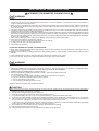
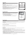
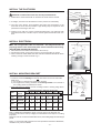
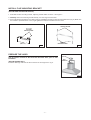
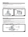
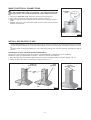
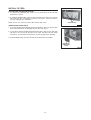
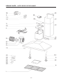
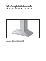
Model
PL36WC50EC
ENGLISH.....................................3
FRANÇAIS................................12
99043841A
READ AND SAVE THESE INSTRUCTIONS
! INTENDED FOR DOMESTIC COOKING ONLY !
WARNING
TO REDUCE THE RISK OF FIRE, ELECTRIC SHOCK, OR INJURY TO PERSONS, OBSERVE THE FOLLOWING:
1. Use this unit only in the manner intended by the manufacturer. If you have questions, contact the manufacturer at the address or
telephone number listed in the warranty.
2. Before servicing or cleaning unit, switch power off at service panel and lock service panel to prevent power from being switched on
accidentally. When the service disconnecting means cannot be locked, securely fasten a prominent warning device, such as a tag,
to the service panel.
3. Installation work and electrical wiring must be done by a qualified person(s) in accordance with all applicable codes and standards,
including fire-rated construction codes and standards.
4. Sufficient air is needed for proper combustion and exhausting of gases through the flue (chimney) of fuel burning equipment to prevent
backdrafting. Follow the heating equipment manufacturer’s guidelines and safety standards such as those published by the National
Fire Protection Association (NFPA), and the American Society for Heating, Refrigeration and Air Conditioning Engineers (ASHRAE),
and the local code authorities.
5. When cutting or drilling into wall or ceiling, do not damage electrical wiring and other hidden utilities.
6. Ducted fans must always be vented to the outdoors.
7. Do not use this unit with any separate solid-state speed control device.
8. To reduce the risk of fire, use only metal ductwork.
9. This unit must be grounded.
TO REDUCE THE RISK OF A RANGE TOP GREASE FIRE:
A. Never leave surface units unattended at high settings. Boilovers cause smoking and greasy spillovers that may ignite. Heat oils
slowly on low or medium settings.
B. Always turn hood ON when cooking at high heat or when flambeing food (i.e. Crepes Suzette, Cherries Jubilee, Peppercorn Beef
Flambe’).
C. Clean ventilating fans frequently. Grease should not be allowed to accumulate on fan or filter.
D. Use proper pan size. Always use cookware appropriate for the size of the surface element.
WARNING
TO REDUCE THE RISK OF INJURY TO PERSONS IN THE EVENT OF A RANGE TOP GREASE FIRE, OBSERVE THE FOLLOWING:*
1. SMOTHER FLAMES with a close-fitting lid, cookie sheet, or metal tray, then turn off the burner. BE CAREFUL TO PREVENT BURNS.
If the flames do not go out immediately, EVACUATE AND CALL THE FIRE DEPARTMENT.
2. NEVER PICK UP A FLAMING PAN - You may be burned.
3. DO NOT USE WATER, including wet dishcloths or towels - violent steam explosion will result.
4. Use an extinguisher ONLY if:
A. You know you have a Class ABC extinguisher and you already know how to operate it.
B. The fire is small and contained in the area where it started.
C. The fire department is being called.
D. You can fight the fire with your back to an exit.
* Based on “Kitchen Fire Safety Tips” published by NFPA.
! CAUTION
1.
To reduce risk of fire and to properly exhaust air, be sure to duct air outside. Do not vent exhaust air into spaces within walls or
ceilings or into attics, crawl spaces, or garages.
2. Take care when using cleaning agents or detergents.
3. Avoid using food products that produce flames under the Range Hood.
4. For general ventilating use only. Do not use to exhaust hazardous or explosive materials and vapors.
5. To avoid motor bearing damage and noisy and/or unbalanced impellers, keep drywall spray, construction dust, etc. off power unit.
6. Your hood motor has a thermal overload which will automatically shut off the motor if it becomes overheated. The motor will restart
when it cools down. If the motor continues to shut off and restart, have the hood serviced.
7. For best capture of cooking impurities, the bottom of the hood should be a minimum of 24" and a maximum of 30" above the cooking
surface. See “Install Mounting Bracket” section for mounting restrictions.
8. Two installers are recommended because of the large size and weight of this hood.
9. Use with approved cord-connection kit only.
10. Please read specification label on product for further information and requirements.
-3-
OPERATION
Controls
The hood is operated using the (4) push-buttons located at eye-level, on the front
edge of the hood.
The light switch turns the halogen lamps on and off.
The blower on-low / off switch turns the blower on to its lowest running speed. The
blower must be turned on using this switch. Turn the blower off by pressing this
switch a second time.
LIGHT
SWITCH
BLOWER
MEDIUM
SPEED
BLOWER
ON-LOW /
OFF
SWITCH
PILOT
LAMP
BLOWER
HIGH
SPEED
The blower medium speed switch changes the blower speed to medium. This
switch works only if the blower is already running at low or high speed.
The blower high speed switch changes the blower speed to high. This switch works
only if the blower is already running at low or medium speed.
The pilot lamp lights up whenever the blower is on.
FIG. 1
HALOGEN BULBS
This range hood requires two halogen bulbs (Type GU10, MR16 shielded, 120V,
50W).
ALWAYS SWITCH OFF THE ELECTRICITY SUPPLY BEFORE CARRYING OUT
ANY OPERATIONS ON THE APPLIANCE.
1. Loosen the ring nut by turning it counterclockwise.
2. Loosen the bulb by turning it counterclockwise; pull the bulb downwards to
remove. CAUTION: BULB MAY BE HOT!
3. Replace with Type GU10, MR16 shielded, 120V, 50W halogen bulb.
BULB
RING NUT
FIG. 2
MAINTENANCE
Proper maintenance of the Range Hood will assure proper performance of the unit.
Grease Filters
The grease filters should be cleaned frequently. Use a warm detergent solution. Grease filters are dishwasher safe.
See “INSTALL FILTERS” section for removal and installation instructions.
Non-Ducted Recirculation Filter
The non-ducted recirculation filter should be changed every 6 months.
See “INSTALL FILTERS” section for removal and installation instructions.
Hood Cleaning
Stainless steel is one of the easiest materials to keep clean. Occasional care will help preserve its fine appearance.
Cleaning tips:
● Hot water with soap or detergent is all that is usually needed.
● Follow all cleaning by rinsing with clear water. Wipe dry with a clean, soft cloth to avoid water marks.
● For discolorations or deposits that persist, use a non-scratching household cleanser or stainless steel polishing
powder with a little water and a soft cloth.
● For stubborn cases, use a plastic scouring pad or soft bristle brush together with cleanser and water. Rub lightly in
direction of polishing lines or "grain" of the stainless finish. Avoid using too much pressure which may mar the surface.
● DO NOT allow deposits to remain for long periods of time.
● DO NOT use ordinary steel wool or steel brushes. Small bits of steel may adhere to the surface causing rust.
● DO NOT allow salt solutions, disinfectants, bleaches, or cleaning compounds to remain in contact with stainless steel
for extended periods. Many of these compounds contain chemicals which may be harmful. Rinse with water after
exposure and wipe dry with a clean cloth.
Painted surfaces should be cleaned with warm water and mild detergent only.
-4-
PREPARE THE HOOD
Unpack hood and check contents.
You should receive:
1 - Hood
1 - Decorative Flue Assembly
1 - Parts Bag containing:
1 - Mounting Bracket
1 - Discharge Collar
1 - Flue Mounting Bracket
8 - Mounting Screws (4.8 x 38mm Pan Head)
4 - Mounting Screws (3.9 x 9.5mm Pan Head)
2 - Mounting Screws (3.9 x 6mm Flat Head)
8 - Drywall Anchors
1 - Installation Instructions
DISCHARGE
COLLAR
MOUNTING
BRACKET
4 MOUNTING
SCREWS (3.9 x
9.5mm Pan Head)
2 MOUNTING BRACKET
SCREWS
(3.9 x 6mm Flat Head)
DECORATIVE
FLUE
FLUE MOUNTING
BRACKET
8 MOUNTING SCREWS
(4.8 x 38mm Pan Head)
8 DRYWALL
ANCHORS
FIG. 3
-5-
INSTALL THE DUCTWORK
(DUCTED HOODS ONLY)
!
ROOF CAP
6”
ROUND DUCT
CAUTION: To reduce the risk of fire, use only metal ductwork.
1. Decide where the ductwork will run between the hood and the outside.
2. A straight, short duct run will allow the hood to perform most efficiently.
3. Long duct runs, elbows, and transitions will reduce the performance of the
hood. Use as few of them as possible. Larger ducting may be required for best
performance with longer duct runs.
4. Install a roof or wall cap. Connect round metal ductwork to cap and work back
towards hood location. Use duct tape to seal the joints between ductwork sections.
DECORATIVE
FLUE
WALL
CAP
HOOD
ROUND
ELBOW
24” TO 30” ABOVE
COOKING SURFACE (see
“INSTALL MOUNTING
BRACKETS” section for
mounting restrictions
6”
ADAPTER
FIG. 4
INSTALL ELECTRICAL
CEILING
WARNING: Electrical wiring must be done by a qualified person(s) in accordance with all applicable codes and standards. This range hood must be
properly grounded. Turn off electrical power at service entrance before wiring.
(DUCTED AND NON-DUCTED HOODS)
1. Plan where the hood will be located above the cook top.
2. Run electrical cable, 2-wire plus ground, to the hood location as shown.
3. Flues conceal the cable. Make sure cable exits the wall within dimensions shown
and long enough to reach the hood. Fig. 5.
8”
12”
4”
CABLE
FIG. 5
INSTALL MOUNTING BRACKET
FRAMING BEHIND WOOD CROSS
SUPPORT
(DUCTED AND NON-DUCTED HOODS)
1. Construct wood wall framing that is flush with interior surface of wall studs.
Make sure:
a) the framing is centered over installation location.
b) the height of the framing will allow the mounting bracket to be secured to
the framing within the dimensions shown.
2. After wall surface is finished, secure mounting bracket to framing using dimensions shown.
HOOD DISTANCE ABOVE 36” HIGH COOK TOP (see note a)
25”
26”
27”
28”
29”
30”
CEILING
HEIGHT
DUCT
METHOD
24”
8-FOOT
DUCTED
39”
8-FOOT
NON-DUCTED
39”
40”
41”
42”
9-FOOT
DUCTED OR
NON-DUCTED
39”
40”
41”
42”
43”
44”
45”
DUCTED
39”
40”
41”
42”
43”
44”
45”
10-FOOT
(see note b)
MOUNTING BRACKET LOCATION ABOVE 36” HIGH COOK TOP
40”
41”
42”
43”
44”
DRYWALL
WOOD
CROSS
SUPPORT
FIG. 6
Note a - Minimum hood distance above cook top must not be less than 24”.
A maximum 30” above cook top is highly recommended for best capture of cooking
impurities.
Distances over 30” are at the installers discretion; and if ceiling height and flue length
permit.
Note b - a 10-foot high ceiling requires use of an optional flue extension FXWC50EC,
available from your local dealer.
-6-
INSTALL FLUE MOUNTING BRACKET
(DUCTED AND NON-DUCTED HOODS)
1. Assemble the flue mounting bracket, adjusting outside width as shown. See Figure 7.
2. Carefully center the mounting bracket directly over the range hood location.
3. Secure the bracket assembly to the ceiling using (2) 4.8x38mm mounting screws and drywall anchors (Fig. 8). Make sure
the bracket is pushed into the corner, tight against the wall and centered over the hood.
FLUE MOUNTING BRACKET
DRYWALL ANCHORS
3.9 x 6 mm
FLAT HEAD
BRACKET SCREWS
9-13/16”
(248.6 mm)
4.8x38mm
MOUNTING SCREWS
FIG. 7
FIG. 8
PREPARE THE HOOD
Note: On stainless steel hoods, carefully remove the plastic protective film
from all exterior surfaces of the hood and decorative flues, prior to final
installation.
(DUCTED HOODS ONLY)
Install the discharge collar into the duct connector of the range hood. Fig. 9.
DISCHARGE
COLLAR
DUCT
CONNECTOR
FIG. 9
-7-
PREPARE THE HOOD
(NON - DUCTED HOODS ONLY)
Note: The following materials must be purchased separately for non-ducted recirculation installations.
• Non - Ducted Recirculation Kit, Model DFKTWC50EC.
•
5” diameter metal duct.
1. Discard discharge collar supplied with the hood. Install the 5” to 6” adapter supplied with the Non-Ducted Recirculation
Kit. Fig. 10.
2. Secure the plenum to the flue mounting bracket with (2) 3.9x6mm flat head screws (the screws are supplied with the
Non-Ducted Recirculation Kit). Fig.11.
5”-6”
ADAPTER
FLUE MOUNTING
BRACKET
3.9x6mm
FLAT HEAD
SCREWS
PLENUM
FIG.10
FIG.11
INSTALL THE HOOD
Note: at least two people will be required to mount the hood.
1. Raise the hood into its mounting position.
2. Align the rectangular opening on the back of the hood with the wall-mounting bracket. Gently lower the hood until it
securely engages the bracket. Fig. 12.
3. Level the hood with (2) mounting screws (3.9x9.5mm) and secure with (4) mounting screws. Use drywall anchors
provided if wall studs or framing are not available. Fig. 12.
4. On ducted hoods, attach 6” round metal duct between the hood’s blower collar and duct that leads to the outside location.
5. On non-ducted hoods, attach 5” round metal duct between the 5”-6” adapter on the hood and the connector on the
plenum.
6. Tape all duct joints to make them secure and air tight.
MOUNTING SCREWS
(3.9x9.5mm)
MOUNTING SCREWS
(4.8x38mm)
WALL FRAMING
MOUNTING
BRACKET
MOUNTING SCREWS
(4.8x38mm)
DRYWALL
ANCHORS
RECTANGULAR
CUTOUT
FIG.12
-8-
MAKE ELECTRICAL CONNECTIONS
WARNING: Electrical wiring must be done by a qualified person(s) in accordance with all applicable codes and standards. This range hood must be
properly grounded. Turn off electrical power at service entrance before wiring.
1. Remove the wiring box cover. Remove a knockout from the wiring box.
2. Secure the conduit to the wiring box through a conduit connector.
3. Make electrical connections. Connect white to white, black to black and green to
green.
4. Replace wiring box cover and screws. Make sure that wires are not pinched
between cover and box.
WIRING BOX
COVER
FIG.13
INSTALL DECORATIVE FLUES
1. Carefully place the decorative flue on the hood. Fig. 14.
- On ducted installation in rooms with 8-foot ceilings, the air vents are concealed. Install the flue with the air vents down.
- On non-ducted installations in rooms with 8-foot ceilings, the air vents are exposed. Install the flue with the air vents
up.
- On ducted and non-ducted installations in rooms with 9-foot ceilings, the vents are exposed. Install the flue with air
vents up.
ROOMS WITH 10-FOOT CEILINGS (DUCTED HOODS ONLY)
Rooms with 10-foot ceilings require flue extension model FXWC50EC available from your local dealer.
Discard the upper flue supplied with the product. Replace it with the flue extension.
2. Raise the upper flue until its holes align with holes in the flue mounting bracket (located on ceiling). Fig. 15.
3. Secure the upper flue with (2) 3.9x9.5mm mounting screws. Fig. 15.
UPPER FLUE
VENTS
CONCEALED
UPPER FLUE
VENTS EXPOSED
3.9x9.5mm
MOUNTING SCREWS
UPPER
FLUE
LOWER
FLUE
LOWER
FLUE
FIG. 14
-9-
FIG.15
INSTALL FILTERS
(DUCTED AND NON-DUCTED HOODS)
1. To remove the GREASE filter, push in on the metal latch tab and tilt filter
downward to remove.
2. To install the GREASE filter, align rear filter tabs with slots in the hood. Depress
the metal latch tab, push filter into position and release. Make sure filter is
securely engaged after installation.
NOTE: Prior to use, remove protective film from the filter frame.
GREASE FILTERS
FIG.16
(NON-DUCTED HOODS ONLY)
1. To remove the NON-DUCTED RECIRCULATION filter, push-in on the front filter
latch. Pull the filter down to disengage the rear filter tabs. Fig. 17.
2. To install the NON-DUCTED RECIRCULATION filter, align the rear filter tabs
with slots in the hood. Push the filter up into place until the front latch snaps
securely into its slot. Make sure the filter is securely engaged after assembly.
3. Install GREASE filters after Non-ducted Recirculation filter is installed.
NON-DUCTED
RECIRCULATION
FILTER
FIG.17
- 10 -
Major Appliance Warranty Information
Your appliance is covered by a one year limited warranty. For one year from your original date of
purchase, Electrolux will pay all costs for repairing or replacing any parts of this appliance that prove to
be defective in materials or workmanship when such appliance is installed, used and maintained in
accordance with the provided instructions.
Exclusions
This warranty does not cover the following:
1. Products with original serial numbers that have been removed, altered or cannot be readily
determined.
2. Product that has been transferred from its original owner to another party or removed outside the USA
or Canada.
3. Rust on the interior or exterior of the unit.
4. Products purchased "as-is" are not covered by this warranty.
5. Food loss due to any refrigerator or freezer failures.
6. Products used in a commercial setting.
7. Service calls which do not involve malfunction or defects in materials or workmanship, or for
appliances not in ordinary household use or used other than in accordance with the provided
instructions.
8. Service calls to correct the installation of your appliance or to instruct you how to use your appliance.
9. Expenses for making the appliance accessible for servicing, such as removal of trim, cupboards,
shelves, etc.,which are not a part of the appliance when it is shipped from the factory.
10. Service calls to repair or replace appliance light bulbs, air filters, water filters, other consumables, or
knobs, handles, or other cosmetic parts.
11. Surcharges including, but not limited to, any after hour, weekend, or holiday service calls, tolls, ferry
trip charges, or mileage expense for service calls to remote areas, including the state of Alaska.
12. Damages to the finish of appliance or home incurred during installation, including but not limited to
floors, cabinets, walls, etc.
13. Damages caused by: services performed by unauthorized service companies; use of parts other than
genuine Electrolux parts or parts obtained from persons other than authorized service companies; or
external causes such as abuse, misuse, inadequate power supply, accidents, fires, or acts of God.
DISCLAIMER OF IMPLIED WARRANTIES; LIMITATION OF REMEDIES
CUSTOMER’S SOLE AND EXCLUSIVE REMEDY UNDER THIS LIMITED WARRANTY SHALL BE
PRODUCT REPAIR OR REPLACEMENT AS PROVIDED HEREIN. CLAIMS BASED ON IMPLIED
WARRANTIES, INCLUDING WARRANTIES OF MERCHANTABILITY OR FITNESS FOR A PARTICULAR
PURPOSE, ARE LIMITED TO ONE YEAR OR THE SHORTEST PERIOD ALLOWED BY LAW, BUT NOT
LESS THAN ONE YEAR. ELECTROLUX SHALL NOT BE LIABLE FOR CONSEQUENTIAL OR
INCIDENTAL DAMAGES SUCH AS PROPERTY DAMAGE AND INCIDENTAL EXPENSES RESULTING
FROM ANY BREACH OF THIS WRITTEN LIMITED WARRANTY OR ANY IMPLIED WARRANTY. SOME
STATES AND PROVINCES DO NOT ALLOW THE EXCLUSION OR LIMITATION OF INCIDENTAL OR
CONSEQUENTIAL DAMAGES, OR LIMITATIONS ON THE DURATION OF IMPLIED WARRANTIES, SO
THESE LIMITATIONS OR EXCLUSIONS MAY NOT APPLY TO YOU. THIS WRITTEN WARRANTY GIVES
YOU SPECIFIC LEGAL RIGHTS. YOU MAY ALSO HAVE OTHER RIGHTS THAT VARY FROM STATE TO
STATE.
If You Need
Service
Keep your receipt, delivery slip, or some other appropriate payment record to establish the warranty period
should service be required. If service is performed, it is in your best interest to obtain and keep all receipts.
Service under this warranty must be obtained by contacting Electrolux at the addresses or phone numbers
below.
This warranty only applies in the USA and Canada. In the USA, your appliance is warranted by Electrolux Major Appliances
North America, a division of Electrolux Home Products, Inc. In Canada, your appliance is warranted by Electrolux Canada
Corp. Electrolux authorizes no person to change or add to any obligations under this warranty. Obligations for service and
parts under this warranty must be performed by Electrolux or an authorized service company. Product features or
specifications as described or illustrated are subject to change without notice.
USA
1.800.944.9044
Electrolux Major Appliances
North America
P.O. Box 212378
Augusta, GA 30907
Canada
1.800.668.4606
Electrolux Canada Corp.
5855 Terry Fox Way
Mississauga, Ontario, Canada
L5V 3E4
- 11 -
SERVICE PARTS - LISTE PIECES DE RECHANGE
MODELS PL36WC50EC
KEY No.
9
14
16
26
45
48
49
53
62
64
67
86
113
115
116
118
119
120
152
165
223
228
229
230
234
240
250
332
407
998
ALA
DESCRIPTION (ENGLISH )
N.
Grease Filter
Motor Capacitor
Wiring Plate
Lamp Bulb
Blower
Motor
Blower Wheel
Rubber Washer
Blower Mounting Cover
Filter support
Cable
Discharge Collar
Logo
Wiring Box
Wiring Box Cover
Decorative Flue Bottom
Decorative Flue Top
Flue Mounting Bracket
Feeder Cable Clamp
Motor Capacitor Box
Switch Button
Controls Board
Warning lamp
Switch board box cover
Switch board box
Switch Actuator
Ring Nut
Cover
Blower Support Bracket
Hardware Package
Halogen Support Assembly
9
14
16
26
45
48
49
53
62
64
67
86
113
115
116
118
119
120
152
165
223
228
229
230
234
240
250
332
407
998
ALA
- 21 -
DESCRIPTION (FRANCAIS)
Filtre à graisse
Condensateur
Plaque du système electrique
Ampoule
Convoyer
Moteur
Turbine
Pare chocs
Support moteur
Support filtre
Cable
Bride de raccordement
Plaquette logo
Boîte de connexion electrique
Couvercle boîte de connexion electrique
Conduit décoratif inférieur
Conduit décoratif supérieur
Etrier de support
Serre cable
Boîte condensateur
Bouton
Circuite commandes
Voyant lumineux
Couvercle commandes
Boîte commandes
Sous-bouton
Bague
Bouchon
Etrier support convoyer
Accessoires de fixation
Ensemble support lampe halogène
SERVICE PARTS - LISTE PIECES DE RECHANGE
MODEL PL36WC50EC
- 22 -