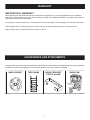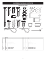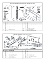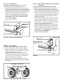
1
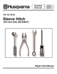
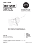
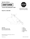
Owner's Manual
STOP
®
48" SNOW BLADE
Model No. 486.244283
DO NOT RETURN TO STORE
For Missing Parts or Assembly
Questions Call 1-866-576-8388
Most fasteners are readily available
through any hardware store
CAUTION:
Before using this product, read
this manual and follow all Safety
Rules and Operating Instructions.
•
•
•
•
•
Safety
Assembly
Operation
Maintenance
Parts
Sears, Roebuck and Co., Hoffman Estates, IL 60179 U.S.A.
www.sears.com/craftsman
PRINTED IN U.S.A.
FORM NO. 49828 (1/06)
TABLE OF CONTENTS
SAFETY RULES ............................................................. 2
WARRANTY ................................................................... 3
ACCESSORIES .............................................................. 3
FULL SIZE HARDWARE CHART ................................... 4
CARTON CONTENTS .................................................... 5
ASSEMBLY ................................................................ 6-13
OPERATION ............................................................ 14-15
MAINTENANCE ........................................................... 15
SERVICE AND ADJUSTMENTS .................................. 16
STORAGE .................................................................... 16
TROUBLESHOOTING.................................................. 16
REPAIR PARTS ILLUSTRATION ................................. 18
REPAIR PARTS LIST ................................................... 19
PARTS ORDERING/SERVICE ..................BACK COVER
SAFETY
Any power equipment can cause injury if operated improperly or if the user does not understand how to operate the equipment.
Exercise caution at all times, when using power equipment.
1. Read the tractor and snow blade owner's manuals and
know how to operate your tractor before using tractor
with snow blade attachment.
3. Never allow children to operate tractor and snow
blade, and do not allow adults to operate without
proper instructions.
2. Never operate tractor and snow blade without wearing
proper clothing suited to weather conditions and
operation of controls.
4. Always begin with transmission in first (low) gear and
gradually increase speed as required.
Look for this symbol to point out important safety precautions. It means--Attention!! Become
alert!! Your safety is involved.
The model number and serial numbers will be found on a
decal attached to the snow blade.
You should record both the serial number and the date of
purchase and keep in a safe place for future reference.
2
MODEL NUMBER:
486.244283
SERIAL NUMBER:
__________________
DATE OF PURCHASE:
__________________
WARRANTY
ONE YEAR FULL WARRANTY
When operated and maintained according to the instructions supplied with it, if this Snow Blade fails due to a defect in
material or workmanship within one year from the date of purchase, call 1-800-4-MY-HOME® to arrange for free repair (or
replacement if repair proves impossible).
If this product is used for commercial or rental purposes, this warranty applies for only 90 days from the date of purchase.
This warranty gives you specific legal rights, and you may also have other rights which vary from state to state.
Sears, Roebuck and Co., D817WA, Hoffman Estates, IL 60179
ACCESSORIES AND ATTACHMENTS
These and other accessories are recommended for use with your unit. Call 1-800-4-MY-HOME® to find out if they are available.
If available, they may be purchased at most Craftsman outlets or by calling 1-800-4-MY-HOME®.
WHEEL WEIGHT
TIRE CHAINS
WEIGHT BRACKET
FOR DRAW
A BAR
AW
3
SNOW CAB
HARDWARE PACKAGE CONTENTS
(SHOWN FULL SIZE)
A
B
I
N
J
O
D
C
P
K
Q
L
M
R
E
F
G
H
S
V
U
REF.
QTY.
A
B
C
D
E
F
G
H
I
J
K
1
1
4
1
2
1
4
18
3
5
22
DESCRIPTION
REF.
L
M
N
O
P
Q
R
S
T
U
V
W
Hex Bolt, 1/4" x 3-1/4" LG.
Hex Bolt 1/4" x 1-1/4"
Hex Bolt, 5/16" x 1"
Hex Bolt, 5/16" x 1-1/2"
Hex Bolt, 3/8" x 1"
Hex Bolt, 1/2" x 1-3/4"
Carriage Bolt 3/8" x 1-1/4"
Carriage Bolt, 3/8" x 1"
Nylock Nut, 1/4"
Nylock Nut, 5/16"
Nylock Nut, 3/8"
4
QTY.
1
4
2
2
3
1
2
1
2
3
4
2
T
W
DESCRIPTION
Nylock Nut, 1/2"
Hex Jam Nut, 5/16"
Palnut, 3/8"
Lock Washer, 3/8"
Washer 1/2"
Clevis Pin, 5/8" x 1-3/4"
Clevis Pin, 1/2" x 1"
Spacer, 5/8" LG.
Spacer, 1" LG.
Hairpin Cotter, Large
Hairpin Cotter, Small
Cotter Pin 1/8" x 1-1/4"
PARTS IN HARDWARE PACKAGES NOT SHOWN FULL SIZE
BB
AA
II
HH
EE
KK
GG
CC
JJ
LL
DD
FF
MM
REF.
QTY.
AA
BB
CC
DD
EE
FF
2
1
1
2
1
1
DESCRIPTION
REF.
Cable End Fitting
Cable Mount Bracket
Angle Lock Spring
Nylon Tie
Spring Mount Rod
Channel Pivot Pin
GG
HH
II
JJ
KK
LL
MM
QTY.
1
1
1
2
1
2
1
DESCRIPTION
Blade Adjust Spring
Plastic Grip
Grip Assembly
Angle Lock Bar
Blade Pivot Shaft
Frame Bracket
Rear Locating Bracket
CARTON CONTENTS (Loose Parts in Carton)
4
1
7
2
6
3
11
5
8
9
12
10
REF.
QTY.
1
2
3
4
5
6
1
1
1
1
1
1
DESCRIPTION
Long Hanger Bracket
Short Hanger Bracket
Rear Mounting Bracket
Pivot Support Bracket
Thrust Channel
Channel Assembly
5
REF.
QTY.
7
8
9
10
11
12
1
1
1
1
2
1
DESCRIPTION
Blade Assembly
Blade Pivot Rod
Lift Handle Tube
Lift Handle Rod
Rear Support Channel
Cable
OPERATION
TOOLS REQUIRED FOR ASSEMBLY
(1)
(1)
(1)
(1)
(2)
(2)
INSTRUCTIONS FOR TRACTORS WITH SINGLE
FRONT DECK SUSPENSION BRACKETS
Pliers
Hammer
Adjustable Wrench (or socket set)
9/16" Open End or Box End Wrench
7/16" Open End or Box End Wrench
1/2" Open End or Box End Wrench
STEP 2: (SEE FIGURE 2)
Use figure 2 to help identify the mounting holes for
Sears tractor frames. For other brand tractors, identify
the two mounting holes by placing a frame bracket
against the tractor frame in front of the front axle and
finding two holes in the tractor frame that align with
two of the holes in the frame bracket. The bracket can
be flipped over to reverse the hole pattern. Refer also
to the illustrations on page 9.
• Remove any bolts found in the mounting holes.
• On Sears tractors, remove the browning shield from
the front of the tractor as shown.
IMPORTANT: Be sure to reattach the browning shield in
step 3.
•
REMOVAL OF PARTS FROM CARTON
•
Remove the loose parts and the hardware packages
from the carton. Lay out all parts and hardware and
identify using the illustrations on pages 4 and 5.
IMPORTANT: You will not use all of the parts or hardware
supplied with your blade. Dispose of unused parts or
hardware after you have finished assembling the blade.
CAUTION: Do not begin assembling
until the tractor engine, muffler and exhaust
deflector have been allowed to cool off.
TRACTOR PREPARATION
•
•
Allow engine, muffler and exhaust deflector to cool
before beginning.
Refer to tractor owner's manual to remove mower
deck or any other attachment you may have mounted
to your tractor. Mark and save all removed parts.
FRAME
BRACKET
REMOVE BROWNING
SHIELD ON SEARS
TRACTORS
FIGURE 2 - SEARS TRACTOR SHOWN
STEP 3: (SEE FIGURE 3)
IMPORTANT: Right hand (R.H.) and left hand (L.H.) are
determined from the operators position while seated on
the tractor.
•
STEP 1: (SEE FIGURE 1)
•
MOUNTING
HOLES ON
SEARS TRACTORS
Look under the front of your tractor. If there is a single
mower deck suspension bracket located underneath
the middle of the front axle, continue on to step 2.
If not, skip to step 7 on page 8 for tractors with dual
mower deck suspension brackets.
•
Attach a frame bracket to each side of the tractor
frame. On Sears tractors use a 3/8" x 1" hex bolt
(E) and 3/8" lock washer (O) in the lower hole and a
3/8" x 1" carriage bolt (H) and 3/8" nylock nut (K) in
the upper hole of each frame bracket. Leave out the
upper bolt if there is no hole in the tractor frame. Do
not tighten. For other brand tractors use the bolts
and nuts shown in the illustrations on page 9.
On Sears tractors re-attach the browning shield.
3/8" NYLON
LOCK NUT (K)
3/8" X 1"
CARRIAGE BOLT (H)
FRAME BRACKET
MOWER DECK
SUSPENSION
BRACKET
3/8" LOCK WASHER (O)
3/8" X 1" HEX BOLT (E)
FIGURE 1 - SEARS TRACTOR SHOWN
FIGURE 3 - SEARS TRACTOR SHOWN
6
STEP 6: (SEE FIGURE 6 AND THE ILLUSTRATIONS
STEP 4: (SEE FIGURE 4)
ON PAGE 9)
This step is for tractor brands other than Sears.
If you have a Sears tractor, skip to step 9 on page 10.
• Refer to the illustrations on page 9 for examples of
how to attach the Hanger Brackets on various tractors.
• Select the set of slots in the top of the Thrust Channel
that will postion the channel's front plate slightly out in
front of the tractor frame. The distance from the slots
to the front plate must be slightly greater than the
distance "L" in step 5.
• Hold the Hanger Brackets with the ends pointing up.
Stack the short Hanger Bracket on top of the long
Hanger Bracket. If distance "H" measured in step 5
was less than 6", hold the brackets together and flip
them over so that the ends point down.
• Slide the Hanger Brackets apart so that the overall
length is slightly less than distance "W" measured
in step 5. Center the Hanger Brackets on top of the
Thrust Channel and attach them to the selected slots
using two 3/8" x 1-1/4" carriage bolts (G) and 3/8"
nylock nuts (K). Do not tighten.
• Proceed to step 9 on page 10.
This step is for Sears tractors only. If you have a
tractor brand other than Sears, skip to step 5.
• Stack the short Hanger Bracket on top of the long
Hanger Bracket with the ends of the brackets pointing
up. Align the first and third slots in both brackets with
the middle set of slots in the thrust channel as shown.
• Fasten the brackets to the thrust channel using
two 3/8" x 1-1/4" carriage bolts (G) and 3/8" nylock
nuts (K). Spread the brackets so that the ends are
approximately 12-1/4" apart, measured from the
outside. Do not tighten.
• Skip to step 9 on page 10.
3/8" x 1-1/4"
CARRIAGE BOLT (G)
"
1/4
12-
SHORT HANGER
BRACKET
LONG HANGER
BRACKET
3/8" NYLOCK NUT (K)
FIGURE 4 - SEARS TRACTOR SHOWN
FRONT PLATE
3/8" x 1-1/4"
CARRIAGE BOLT (G)
HANGER BRACKETS
Ends down when "H" is 6" or less
Ends up when "H" is more than 6"
W
STEP 5: (SEE FIGURE 5)
This step is for tractor brands other than Sears.
If you have a Sears tractor, skip to step 9 on page 10.
• Measure the distance from the center of the frame
brackets to the front of the tractor frame. This will be
referred to as distance "L" in step 6.
• Measure to determine which of the two holes at
the bottom of the Frame Bracket is closest to being
6" from the ground. The height of this hole will be
referred to as distance "H" in step 6.
• Measure the inside distance between the Frame
Brackets. This distance will be referred to as distance
"W" in step 6.
3/8" NYLOCK NUT (K)
L
FIGURE 6
JOHN DEERE LT TRACTOR
W
H
L
FIGURE 5 - JOHN DEERE TRACTOR LT SHOWN
7
STEP 8: (SEE FIGURE 8 AND THE ILLUSTRATIONS
INSTRUCTIONS FOR TRACTORS WITH DUAL
FRONT DECK SUSPENSION BRACKETS
•
STEP 7: (SEE FIGURE 7)
•
•
•
•
•
Locate the Mower Deck Suspension Brackets on each
side at the front of the tractor frame. A Sears tractor
is shown below. For examples of brackets on other
tractors see the illustrations on page 9.
Measure the distance from the center of the deck
attachment hole in the Mower Deck Suspension
Brackets to the front of the tractor frame. This will be
referred to as distance "L" in step 8.
Measure the height above the ground of the deck
attachment hole in the Mower Deck Suspension
Brackets. The height of this hole will be referred to as
distance "H" in step 8.
Measure the inside distance between the Mower
Deck Suspension Brackets. This will be referred to as
distance "W" in step 8.
•
•
•
SEARS (LT) TRACTOR FRAME
ON PAGE 9)
Refer to the illustrations on page 9 for examples of
how to attach the Hanger Brackets on various tractors.
Select a set of slots in the top of the Thrust Channel
that will position the front plate slightly out in front of
the tractor frame. The distance from the slots to the
front plate must be slightly greater than the distance
"L" in step 7.
Hold the Hanger Brackets with the ends pointing up.
Stack the short Hanger Bracket on top of the long
Hanger Bracket. If distance "H" measured in step 7
was less than 6", hold the brackets together and flip
them over so that the ends point down.
Slide the Hanger Brackets apart so that the overall
length is slightly less than distance "W" measured
in step 7. Center the Hanger Brackets on top of the
Thrust Channel and attach them to the selected slots
using two 3/8" x 1-1/4" carriage bolts (G) and 3/8"
nylock nuts (K). Do not tighten.
Proceed to step 9 on page 10.
FRONT PLATE
3/8" x 1-1/4"
CARRIAGE BOLT (G)
L
H
W
HANGER BRACKETS
SUSPENSION
BRACKET
Ends down when "H" is 6" or less
Ends up when "H" is more than 6"
W
GROU
ND
FIGURE 7 - SEARS TRACTOR SHOWN
3/8" NYLOCK NUT (K)
L
FIGURE 8
8
SEARS TRACTORS WITH
CENTER SUSPENSION BRACKET
JOHN DEERE LT
3/8" x 1"
CARRIAGE
BOLT
12.75"
13"
5/16" x 1"
HEX BOLT
3/8" x 1"
HEX BOLT
FRAME
BRACKET
FRAME
BRACKET
LOCATE HANGER BRACKETS IN
MIDDLE SET OF SLOTS IN THRUST CHANNEL
LOCATE HANGER BRACKETS IN FRONT
SET OF SLOTS IN THRUST CHANNEL
MURRAY TRACTORS
SEARS LAWN
TRACTORS
8.5"
9.75"
TRACTOR
SUSPENSION
BRACKET
TRACTOR
SUSPENSION
BRACKET
LOCATE HANGER BRACKETS IN REAR
SET OF SLOTS IN THRUST CHANNEL
FORWARD SLOTS MAY BE USED ON
SOME MURRAY TRACTORS
LOCATE HANGER BRACKETS IN
MIDDLE SET OF SLOTS IN THRUST CHANNEL
SEARS GARDEN
TRACTORS
JOHN DEERE SABRE
13"
12"
3/8" x 1"
CARRIAGE
BOLT
TRACTOR
SUSPENSION
BRACKET
FRAME
BRACKET
LOCATE HANGER BRACKETS IN FRONT
SET OF SLOTS IN THRUST CHANNEL
LOCATE HANGER BRACKETS IN
MIDDLE SET OF SLOTS IN THRUST CHANNEL
MTD GARDEN
TRACTORS
MTD - LAWN TRACTORS
WITH FAST ATTACH FEATURE
13"
13"
TRACTOR
SUSPENSION
BRACKET
TRACTOR
SUSPENSION
BRACKET
LOCATE HANGER BRACKETS IN FRONT
SET OF SLOTS IN THRUST CHANNEL
LOCATE HANGER BRACKETS IN FRONT
SET OF SLOTS IN THRUST CHANNEL
MTD LAWN
TRACTORS
13"
MTD - GARDEN TRACTORS
WITH FAST ATTACH FEATURE
13"
5/16" x 1"
HEX BOLT
TRACTOR
SUSPENSION
BRACKET
FRAME
BRACKET
LOCATE HANGER BRACKETS IN FRONT
SET OF SLOTS IN THRUST CHANNEL
LOCATE HANGER BRACKETS IN FRONT
SET OF SLOTS IN THRUST CHANNEL
9
STEP 9: (SEE FIGURE 9)
•
•
STEP 12: (SEE FIGURE 12)
Install the Rear Locating Bracket to the top of the
Rear Mounting Bracket using two 3/8" x 1" Carriage
bolts (H) and 3/8" nylock nuts (K). Tighten nuts.
Install the Rear Support Channels to the middle set of
holes in the sides of the Rear Mounting Bracket using
four 3/8" x 1" Carriage Bolts (H) and 3/8" nylock nuts
(K). Finger tighten only.
REAR LOCATING
BRACKET
•
•
REAR SUPPORT
CHANNELS
•
•
•
3/8" X 1"
CARRIAGE BOLT (H)
REAR MOUNTING
BRACKET
3/8" NYLOCK NUT (K)
Place the rear of the Thrust Channel between the
two Rear Support Channels. Install four 3/8" x 1"
carriage bolts (H) and 3/8" nylock nuts (K) using the
most widely spaced holes that are aligned with slots.
Finger tighten only.
If the Rear Support Channels bump against bottom
of the tractor, reattach the rear of the channels to a
lower set of holes in the Rear Mounting Bracket. If
there is more clearance than necessary between the
Rear Support Channels and the bottom of the tractor,
reattach the rear of the channels to a higher set of
holes in the Rear Mounting Bracket.
Spread the Hanger Brackets apart as far as possible
and center the Thrust Channel under the tractor.
Tighten all bolts and nuts installed up to this point.
Measure the height of the front plate on the Thrust
Channel. If it is not 4" to 5" above the ground, reinstall
the clevis pins in the Hanger Brackets to a higher or
lower hole position to attain the correct height.
FIGURE 9
STEP 10: (SEE FIGURE 10)
•
Slide the Rear Support Channels under the rear of
the tractor. Attach the Rear Mounting Bracket to the
Tractor Drawbar using the 5/8" x 1-3/4" Clevis Pin (Q)
and a large Hairpin Cotter (U).
5/8" X 1-3/4"
CLEVIS PIN (Q)
TRACTOR
DRAWBAR
REAR MOUNTING
BRACKET
REAR
SUPPORT
CHANNEL
REAR LOCATING
BRACKET
3/8" X 1"
CARRIAGE BOLT (H)
3/8" NYLOCK
NUT (K)
LARGE
HAIRPIN
COTTER (U)
"
to 5
UND
GRO
FIGURE 12 - SEARS TRACTOR SHOWN
REAR SUPPORT
CHANNEL
STEP 13: (SEE FIGURE 13)
FIGURE 10
•
STEP 11: (SEE FIGURE 11)
•
FRONT
PLATE
4"
Slide the Thrust Channel under the front of the tractor.
Attach the Hanger Brackets to the Frame Brackets
using two 1/2" x 1" clevis pins (R), 1/2" washers (P)
and large hairpin cotters (U).
Assemble the pivot support bracket to the front of the
Thrust Channel using four 3/8" x 1" carriage bolts (H)
and four 3/8" nylock nuts (K). Make sure the bracket is
straight and then tighten.
3/8" NYLOCK
NUT (K)
1/2" WASHER (P)
LARGE HAIRPIN COTTER (U)
3/8" X 1"
CARRIAGE BOLT (H)
1/2"X 1" CLEVIS PIN (R)
FIGURE 13 - SEARS TRACTOR SHOWN
FIGURE 11 - SEARS TRACTOR SHOWN
10
STEP 14: (SEE FIGURE 14)
STEP 16: (SEE FIGURE 16)
•
Place the two angle lock bars together so that all holes
are aligned. Assemble a 3/8" x 1-1/4" carriage bolt (G)
and a 3/8" nylock nut (K) in the top hole. Be sure to
insert bolt from side indicated. Finger tighten only.
• Insert the round hook end of the angle lock spring up
through the hole in bracket (A).
• Hold the angle lock bars so that the square holes are
at the top. Insert the straight hook end of the angle
lock spring through the middle hole in both angle lock
bars as shown.
• Insert the angle lock bars down through the slot in the
channel. Under the channel, place a 1" long spacer (T)
on each side of the angle lock bars and insert a 1/4" x
3-1/4" bolt (A) through the channel, the angle lock bars
and the spacers. Secure the bolt with a 1/4" nylock nut
(I). Tighten so that lock bars can pivot freely.
• At this time tighten the 3/8" carriage bolt and nylon
lock nut previously assembled to angle lock bars.
NOTE: When the angle lock bars are pulled back, the
pivot plate should unlock and be free to pivot.
•
Assemble a 3/8" x 1-1/4" carriage bolt (G) through the
square hole in the cable mount bracket and through
the square hole in the angle lock bars as shown. (The
carriage bolts should face in opposite directions.)
Using pliers hold the cable mount bracket in position,
angling down towards the L.H. hole in the channel as
shown. Secure with a 3/8" nylock nut (K). Tighten.
Refer also to figure 17 for the correct angle for the
cable mount bracket.
3/8" x 1-1/4"
CARRIAGE BOLT (G)
ALIGN CABLE
MOUNT BRACKET
WITH L.H. HOLE
ANGLE
LOCK
BARS
3/8"x 1-1/4"
CARRIAGE BOLT (G)
3/8" NYLOCK
NUT (K)
1/4" NYLOCK
NUT (I)
CHANNEL
1" SPACERS (T)
FIGURE 14
(A)
3/8" NYLOCK
NUT (K)
ANGLE
LOCK
SPRING
(Right Hand Side View)
FIGURE 16
ANGLE
LOCK BARS
STEP 17: (SEE FIGURE 17)
1/4" x 3-1/4"
HEX BOLT (A)
•
(Right Hand Side View)
STEP 15: (SEE FIGURE 15)
•
FRONT
Use a hammer to tap a 3/8" palnut (N) onto one
end of the spring mount rod. Insert the rod through
the rear set of holes in the pivot plate. Support the
assembled end of the spring mount rod on a block of
wood, and tap the remaining 3/8" palnut (N) onto the
other end of the rod.
Assemble one 5/16" jam nut (M) approximately 3/4"
onto the threaded end of the control cable. Assemble
the threaded cable end through the round hole in
the cable mount bracket as shown and secure with
another 5/16" jam nut (M). Tighten.
NOTE: Some adjustment of jam nuts may be required
after blade assembly is completed.
3/4"
CABLE MOUNT
BRACKET
5/16" JAM NUT (M)
5/16" JAM NUT (M)
3/8" PALNUT (N)
SPRING
MOUNT
ROD
PIVOT
PLATE
CHANNEL ASSEMBLY
REAR
3/8" PALNUT (N)
FIGURE 15
FIGURE 17
(Top View)
11
(Left Hand Side View)
STEP 18: (SEE FIGURE 18)
•
•
1/8" x 1-1/4"
COTTER
PIN (W)
Assemble ball end of control cable up through hole in
cable end fitting and pull until ball slips inside curled
edge of fitting as shown. If ball won't slip under edge
of curl it will need to be inserted through open end of
curl.
Assemble 1/4" x 1-1/4" hex bolt (B) down through the
cable end fitting, the 5/8" long spacer (S) and the left
hand hole in the channel assembly. Secure with a 1/4"
nylock nut (I). Tighten.
3/8" HEX NUT
(TOP)
BLADE
PIVOT
SHAFT
3/8" HEX NUT
(BOTTOM)
BLADE
NOTE: Make sure the cable mount bracket is aligned
with the cable end fitting as shown to prevent binding of
cable. The other end of the control cable will be attached
in a later step.
BLADE
ADJUST
SPRING
SPRING
MOUNT
ROD
1/4" x 1-1/4"
HEX BOLT (B)
CABLE END
FITTING
PLASTIC
CAP
1/8" x 1-1/4"
COTTER PIN (W)
PIVOT PLATE
FIGURE 19
(Right Hand Side View)
5/8" SPACER (S)
CHANNEL
ASSEMBLY
STEP 20: (SEE FIGURE 20)
•
•
HOLE
1/4" NYLON LOCK NUT (I)
FIGURE 18
REAR
(Left Hand Side View)
Assemble the 1/2" washer (P) onto the channel pivot
pin.
Attach the channel assembly to the tractor by placing
the end of the channel assembly up inside the pivot
support bracket on the tractor. Align the hole in the
pivot support bracket with the second hole in the
channel assembly. Insert the channel pivot pin through
the aligned holes from the left side and secure with a
small hairpin cotter (V) pushed all the way through to
the loop end.
NOTE: All hairpin cotters on this snow blade should be
pushed through to their loop end.
STEP 19: (SEE FIGURE 19)
•
•
To attach the blade to the channel assembly, align the
notched holes in the pivot plate with the notched holes
in the blade. Insert a 1/8" x 1-1/4" cotter pin (W) down
through the hole at the bend in the blade pivot shaft.
Spread the ends of the pin. From the left side insert
the blade pivot shaft, bend facing up, through the
notched holes. Secure the shaft with another 1/8" x
1-1/4" cotter pin (W) through the end hole in the shaft.
Spread the ends of the pin.
Remove the plastic cap and one 3/8" hex nut from the
bolt in the blade adjust spring. Adjust the remaining
3/8" hex nut down approximately 1" onto the bolt
threads. Hook the spring over the spring mount rod
as shown. Place the bolt up through the hole in the
top edge of the blade and reassemble the other 3/8"
hex nut and tighten down against the top edge of the
blade. Replace the plastic cap over the end of the bolt
threads.
1/2" WASHER (P)
PIVOT SUPPORT
BRACKET
CHANNEL
PIVOT PIN
HOLE IN END OF
CHANNEL ASSEMBLY
SMALL HAIRPIN
COTTER (V)
FIGURE 20
12
CHANNEL
ASSEMBLY
(Right Hand Side View)
STEP 21: (SEE FIGURE 21)
•
•
STEP 23: (SEE FIGURE 23)
From the left side, insert the welded end of the lift
handle rod through the exposed holes in the end of
the channel assembly. Next, insert the lift link pin
through the hole in the bracket that is welded to the lift
handle rod. (The lift link is pre-assembled to the pivot
support bracket). Secure the bracket with a small
hairpin cotter (V) inserted up through the lift link pin all
the way to the loop end of the hair pin cotter.
Using the furnished grease packet, apply a light
coating of grease to the straight upper portion of the
lift handle rod. Slide the lift handle tube onto the rod.
•
•
•
Assemble the plastic grip onto the lock release grip
assembly.
Attach the lock release grip assembly to the lift handle
tube using one 5/16" x 1-1/2" hex bolt (D) and one
5/16" nylock nut (J). Do not overtighten the nylon
lock nut. The grip assembly must pivot freely.
Assemble the ball end of the cable to a cable end
fitting as was done to the other end of the cable.
Secure the cable end fitting to the weld bolt on the
lock release grip with a 1/4" nylock nut (I). Do not
overtighten the nylon lock nut. The cable fitting must
pivot freely.
5/16" x 1-1/2"
HEX BOLT (D)
LIFT HANDLE TUBE
1/4" WELD
BOLT
CABLE END
FITTING
LIFT HANDLE ROD
CABLE
PLASTIC
GRIP
1/4 " NYLOCK
NUT (I)
5/16" NYLOCK
NUT (J)
LONG PIN
(LIFT LINK)
LOCK RELEASE
GRIP ASSEMBLY
WELDED BRACKET
SMALL HAIRPIN COTTER (V)
CABLE
CABLEEND
END
FITTING
FITTING
(Right Hand Side View)
FIGURE 23
(Left Hand Side View)
FIGURE 21
STEP 24: (SEE FIGURE 24)
•
STEP 22: (SEE FIGURE 20)
•
Screw one 5/16" jam nut (M) approximately 3/4" onto
the loose end of the control cable. Pass the cable
around the outside of the lift handle rod and insert the
threaded cable end through the cable mount bracket
on the lift handle tube. Secure the cable with another
5/16" jam nut (M). Tighten.
NOTE: Some adjustment of jam nuts may be required
after blade assembly is completed.
•
Place the long end of the blade pivot rod down
through the blade pivot shaft. Attach the short end of
the blade pivot rod to the lift handle tube. Secure both
ends with small hairpin cotters (V).
Use the two plastic ties to hold the cable securely
to the outside of the handle tube and away from the
tractor to avoid direct heat from the tractor muffler.
PLASTIC TIES
SMALL HAIRPIN
COTTER (V)
CABLE MOUNT BRACKET
BLADE
PIVOT
ROD
BALL
END
5/16" JAM NUTS (M)
BLADE PIVOT SHAFT
HANDLE
GRIP
FIGURE 22
LIFT HANDLE
TUBE
SMALL HAIRPIN COTTER (V)
(Right Hand Side View)
FIGURE 24
13
(Left Hand Side View)
OPERATION
KNOW YOUR SNOW BLADE
Read this owner's manual and safety rules before operating your snowblade.
Compare the illustration below with your snow blade to familiarize yourself with the various controls and their locations.
LIFT HANDLE TUBE
LOCK RELEASE GRIP ASSEMBLY
BLADE PIVOT ROD
ANGLE
LOCK
BARS
BLADE
ADJUST
SPRING
LIFT HANDLE ROD
BLADE SHOE
CONTROL CABLE
BLADE PIVOT SHAFT
LOCK RELEASE GRIP ASS'Y.
LIFT HANDLE TUBE
BLADE PIVOT ROD
ANGLE LOCK BARS
BLADE ADJUST SPRING
BLADE SHOE
BLADE PIVOT SHAFT
LIFT HANDLE ROD
CONTROL CABLE
Unlocks the blade to swivel to the right and left.
Raises or lowers the blade and pivots blade to the right and left.
Connects blade to handle tube. Pivots blade to the right and left.
Locks the blade in either the right hand, left hand or straight ahead position.
Holds blade in position but permits it to pivot forward to pass over an obstruction.
Ground-contacting part of blade. Adjusts for adequate ground clearance of blade.
Connects blade to channel assembly. Allows blade to pivot forward.
Connects lift handle tube to channel assembly. Raises and lowers the blade.
Connects the lock release lever to the angle lock bars.
To Pivot the Blade
HOW TO USE YOUR SNOW BLADE
•
To Raise or Lower the Snow Blade
•
Use the handle grip located on the end of the handle
tube. To raise the blade, pull back while pushing down
on the handle grip. To lower blade, pull back while
lifting up on handle grip. See figure 25.
PULL BACK AND
LIFT UP TO
LOWER BLADE
Raise the blade to transport position. To unlock
the blade, push the lock release grip down against
the handle tube. To pivot the blade, keep the grip
depressed and push forward or pull back on the
handle tube, sliding it along the lift rod. Release the
grip to lock the blade when it is in either the right
hand, the left hand or the straight ahead position. See
figure 26.
LOCK RELEASE
GRIP ASSEMBLY
HANDLE TUBE
HANDLE TUBE
HANDLE GRIP
PULL BACK AND
PUSH DOWN TO
RAISE BLADE
LIFT ROD
FIGURE 26
FIGURE 25
14
Using the Snowblade
CAUTION: Inspect carefully the area
to be worked before operating the snow
blade. Avoid pipes, roots, curbs or other
heavy obstructions.
Wheel weights and tire chains must be used with your
snow blade for traction. These accessories are available
at your nearest Sears retail store. See page 3.
•
Prepare the lawn tractor engine for cold weather using
instructions furnished with the lawn tractor.
•
Always begin with the transmission in first (low) gear
and gradually increase speed as required.
•
Do not repeatedly push snow in the same direction,
causing excessive build up with each successive pass.
•
To reduce icing on the blade, allow the lawn tractor
and blade to adjust to outdoor temperature before
operating.
•
For improved snow removal performance, coat the blade
with automotive type paste wax.
CAUTION: Know the terrain. Avoid
exceptionally steep slopes or drop offs
which may be hidden by the snow.
Never run the snow blade into heavy
material at high speed.
CAUTION: Always lower the blade to
the ground before leaving the tractor.
MAINTENANCE
CUSTOMER RESPONSIBILITIES
•
Read and follow the maintenance schedule and the
procedures listed in the maintenance section.
se e
e
n
h u h us aso orag
c
a ac
e st
e
s
e
e
e
y
for ter ver efor
E
Be Af
B
MAINTENANCE SCHEDULE
Fill in dates as you
complete regular service.
Check for loose fasteners
Check for worn or damaged parts
Clean Blade
Lubricate Blade
•
Service Dates
X
X
X
X
X
During the operating season, check all bolts, nuts and
hairpin cotters to be sure they are secure.
GREASE
Lubrication Points
•
Lubricate all pivot points to help maintain proper
operation of blade. Use grease packet furnished with
the snow blade for lubrication of the upper portion of
the lift handle rod. See figure 27.
LUBRICATE
FIGURE 27
15
LUBRICATE
SERVICE AND ADJUSTMENTS
To Adjust the Blade Pivot Lock Mechanism
To Adjust Blade Spring
•
•
The tension of the blade adjust spring may be altered
to permit the blade to tilt forward to bypass solid
obstructions. To change the spring tension, adjust
the nuts at upper end of the spring bolt. Turn the nuts
counterclockwise to relieve tension and clockwise to
increase tension. Refer to figure 19 on page 12.
To Adjust Blade Shoes
•
The blade shoes at the ends of blade may be raised
for close work on smooth surfaces or lowered to raise
the blade to work on rough or uneven areas. Make
sure both shoes are set evenly and that the nuts are
tightened securely. See figure 28.
If the blade will not unlock and pivot, the angle lock
bars are not disengaging from the slots in the pivot
plate. To correct, adjust the 5/16" hex jam nuts to draw
the end of the control cable back towards the cable
mount bracket. The less the threaded end of the cable
extends through the bracket, the more the angle lock
bars can retract to disengage from the slots in the
pivot plate. See figure 29.
CABLE MOUNT BRACKET
CONTROL
CABLE
5/16" HEX
JAM NUT
5/16" HEX
JAM NUT
FIGURE 29
BLADE SHOE
FIGURE 28
STORAGE
Recommendations When Storing
•
•
•
•
To Remove Blade From Tractor
When the snow blade is not being used, remove all
dirt and rust and touch up with paint.
Touch up bare metal with paint or apply a light coat of
grease or rust preventive.
Lubricate all pivot points and all points shown in figure
27, page 15 in the maintenance section.
Store in a dry area, protected from weather.
•
•
•
•
•
Lower the blade head to the ground with the blade in
the center (straight ahead) position.
Remove the two clevis pins which fasten the
blade's hanger brackets to the tractor's mower deck
suspension brackets (or frame brackets). See figure
11 on page 10.
Remove the clevis pin that fastens the blade's rear
mounting bracket to the tractor's drawbar and drop the
rear of the blade frame to the ground. See figure 10
on page 10.
Remove the frame brackets (if used). See figure 3 on
page 6.
Back the tractor off of the blade assembly.
TROUBLESHOOTING
PROBLEM
CAUSE
CORRECTION
Blade is difficult to raise.
Lift mechanism is binding
Blade is difficult to pivot.
Handle tube is binding on lift rod.
Blade will not unlock to pivot.
Lock mechanism is out of adjustment
and is not disengaging.
Lubricate pivot points as shown in
figure 27 on page 15.
Lubricate lift handle rod as instructed
in figure 27 on page 15.
Refer to the Service and Adjustments
section on this page.
16
NOTES
17
40
43
24
32
51
39
41
54
18
38
58
65
52
6
41
25
47
53
60
64
51
25
27
18
23
52
52
D
36
C
49
52
31
16
37
25
48
41
50
52
51
42
38
51
47
C
26
47
A
A
52
B
11
25
46 45 33
41
30
55
B
35
17
15
36
16
10
52
57
12
56
13
48
8
67
34
51
51
14
19
6
52
9
55
35
63
8
21
58
62
36
3
D
4
6
44
20
21
7
52
61
6
59
6
22
2
4
5
4
51
29 55
28 48 51
59
1
58
61
52
PARTS
REPAIR PARTS LIST FOR MODEL 486.244283 - 48" SNOW BLADE
REF. PART
QTY.
DESCRIPTION
NO.
NO.
1
23955
1
Blade 48"
2
23956
1
Wear Plate 48"
3
62980
1
Reinforcement Plate Assembly
4
43080
6
Bolt, Carriage 5/16-18 x 3/4"
5
44326
4
Bolt, Carriage 5/16-18 x 1"
6
47810
15
Nylon Lock Nut, 5/16-18 Thread
7
43081
4
Washer, 5/16"
8
24690
2
Skid Shoe
9
64732
1
Thrust Channel
10
24347
1
Push Channel
11
43262
1
Hex Lock Nut, 1/2-13 Thread
12
23131
1
Bolt, Special Pivot
13 1540-118 1
Washer, Flat 1/2"
14
23958
1
Plate, Pivot 7 Ga.
15
23130
1
Bracket, Spring Mt.
16
24659
2
Rear Support Channel
17
46066
1
Shaft, Blade Pivot
18
25125
1
Rear Mounting Bracket
19 R9466R
1
Spring, Blade Adjust
20
44071
1
Hex Bolt, 3/8-16 x 3-1/2"
21
43015
2
Hex Nut, 3/8-16 Thread
22
44074
1
Plastic Cap
23 746-0366 1
Control Cable Assembly
24
62561
1
Release Grip Assembly
25
43055
4
Pin, Hairpin Small 3/32"
26
46053
2
Spacer, .28 ID x 1"
27
63033
1
Lift Handle Rod Assembly
28
25121
1
Short Hanger Bracket
29
25122
1
Long Hanger Bracket
30
24023
1
Pivot Support Bracket
31
46049
1
Rod, Blade Pivot
32
62972
1
Lift Handle Tube Assembly
33
23151
2
Angle Lock Bar
REF. PART
QTY.
NO.
NO.
34
23856
1
35
44917
2
36
43010
3
37
43348
1
38 746-0260 2
39 731-0869 1
40
46471
1
41 712-0256 4
42
23658
1
43
43085
1
44
43063
4
45
05762
1
46
1509-90
1
47
47189
3
48 710-0305 4
49
46065
1
50
63034
1
51
43350
18
52 HA21362 22
53 HA23380 1
54 726-0178 2
55 R19171616 3
56
46071
1
57
43349
1
58
43343
3
59
44062
2
60
HA3980
1
61
25124
2
62
43003
2
63
43001
2
64 R74780828 1
65 712-3083 1
49828
1
Spring Mount Rod
Palnut, 3/8"
Cotter Pin 1/8" x 1-1/4"
Angle Lock Spring
Cable End Fitting
Grip, Plastic
Handle, Grip
Hex Jam Nut, 5/16-24 Thread
Spacer
Hex Bolt, 5/16-18 x 1-1/2"
Bolt, Hex 5/16-18 x 1" Lg.
Cable Mount Bracket
Hex Bolt 1/4-20 x 1-1/4"
Nylon Lock Nut, 1/4-20 Thread
Carriage Bolt, 3/8-16 x 1-1/4"
Channel Pivot Pin
Lift Link Assembly
Carriage Bolt, 3/8-16 x 1"
Nylon Lock Nut, 3/8-16 Thread
Rear Locating Bracket
Plastic Tie
Washer
Hex Bolt, 1/4-20 x 3-1/4" Lg. Gr
1/4" x 1" Spring Pin
Pin, 3/32" Hairpin (Large)
Clevis Pin, 1/2" x 1" Lg.
Clevis Pin, 5/8" x 1-3/4" Lg.
Frame Bracket
Lock Washer, 3/8"
Hex Bolt, 3/8-16 x 1"
Hex Bolt, 1/2-13 x 1-3/4"
Nylon Lock Nut, 1/2-13 Thread
Owners Manual
DESCRIPTION
REPAIR PARTS LIST FOR MODEL 486.244283 - 48" SNOW BLADE
19
Get it fixed, at your home or ours!
Your Home
For repair – in your home – of all major brand appliances,
lawn and garden equipment, or heating and cooling systems,
no matter who made it, no matter who sold it!
For the replacement parts, accessories and
owner’s manuals that you need to do-it-yourself.
For Sears professional installation of home appliances
and items like garage door openers and water heaters.
1-800-4-MY-HOME®
(1-800-469-4663)
Call anytime, day or night (U.S.A. and Canada)
www.sears.com
www.sears.ca
Our Home
For repair of carry-in items like vacuums, lawn equipment,
and electronics, call or go on-line for the location of your nearest
Sears Parts & Repair Center.
1-800-488-1222
Call anytime, day or night (U.S.A. only)
www.sears.com
To purchase a protection agreement (U.S.A.)
or maintenance agreement (Canada) on a product serviced by Sears:
1-800-827-6655 (U.S.A.)
1-800-361-6665 (Canada)
Para pedir servicio de reparación
a domicilio, y para ordenar piezas:
Au Canada pour service en français:
1-800-LE-FOYER MC
1-888-SU-HOGAR®
(1-800-533-6937)
www.sears.ca
(1-888-784-6427)
® Registered Trademark / TM Trademark / SM Service Mark of Sears Brands, LLC
® Marca Registrada / TM Marca de Fábrica / SM Marca de Servicio de Sears Brands, LLC
MC Marque de commerce / MD Marque déposée de Sears Brands, LLC
20
© Sears Brands, LLC