1
I.::
Model 241
ARCADE ANALYZER
INSTRUCTION MANUAL
"
PUBLICATION NO. 2490-737
The Hickok Electrical Instrument Company
10!514 DUPONT AVENUE. C LEV ELAND. O HIO 44106 • (a1S} !!>4 1· BOBO • T'NX, 9.0-4 2·' · 8298
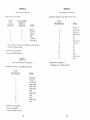
TABLE OF CONTENTS
Section
HICKOK
GENERAL
SPECIFICATIONS AND REFERENCE DATA
Generator
Vari-Traker
General
LIMITED
WARRANTY
"
III
if the registration card is not properly compost marked within ten days after date
this instrument of its manufacture
workmanship for a
of one
(12
subject to the
tAl"r'r"nt~
IV
the first twelve month period after
V
VI
OPERATING INSTRUCTIONS
9
Vari-Traker Instructions
Getting the Most Out of Vari,Traker
Additional Vari-Traker Applications
Generator Operation
10
11
12
RASTER SCAN MONITOR SERVICING
15
X-V MONITOR SERVICING
station
GENERAL CONVERGENCE PROCEDURE
(RASTER SCAN AND X-Y MONITORS)
General
Degaussing
Color Purity
Static Convergence
Dynamic Convergence
Hickok Electrical Instrument Co,
1714 Carrollton Avenue
Jrelenv.tood. Mississippi 38930
4
5
7
General
X-Y Setup
Adjustments
to X·Y Monitors
Display Pattern Uses
must first be contacted,
given for either correcting
Instructions will then
Upon authorization, this equipment should
2
DESCRIPTION OF CONTROLS
General
Raster Scan Setup
Adjustments 'n<."'1"',, to Raster Scan Monitors
Display Pattern Uses
tr",n<nnrt.tltirm prepaid, to the factory for repair
2
13
15
15
15
16
18
18
18
19
19
22
22
22
22
23
23
your locality,
VII
ADAPTERS
24
VIII
MAKING YOUR OWN ADAPTERS
27
IX
MAINTENANCE AND CALIBRATION
30
X
PARTS LIST
32
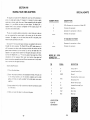
GENERAL
The Model 241 ARCADE ANALYZER is an instrument
designed to efficiently service the
down time
video games. Monitor and control failures represent
encountered with video arcade games. The Model 241
failure elements in a single highly
field use yet quite at home on the bench.
The instrument
The generator portion of the instrument
to troubleshoot and
align both raster scan and X-Y monitors used with video arcade games. The
generator handles both color and black and white monitors. The VAR I
TRAKER is a unique volt/ohmmeter that not
can be used
measure
but also is superb at identifying intermittents and discontinuous controls.
The patterns available on the 241 are
those used by the monitor
manufacturers in their service literature and also include several patterns that
improve serviceability. In addition, the
of all patterns, except the
calibrated X-Y Gray
is front
An X-Y
used for
control that is calibrated at two
ments also allows
of the patterns
convergence and other
cable and 4 prewired
Wells Gardner monitors. At this time these monitors represent over 90% of
monitors in use in video arcade games.
supplied which can be used to wire special adapters for other
The VAR I-TRA KE R is a new concept in
volt/ohmmeter
to
troubleshoot common video games problems. The VARI·TRAKER uses a
continuously variable audio tone to indicate the value of the
measuring. A short use period will allow the user to
resistances by the sound of the tone. What is
VARI-TRAKER is that it not only allows value measurements but
sound instead of meters or
has the
property of
intermittents, the presence of small amounts of AC
on DC
discontinuities in potentiometers and
hard to find, problems.
The Model 241 ARCADE ANALYZE R
real contribution to the maintenance technology of video arcade games. It also
in other
devices which use video monitors as an
element of
with people. The 241 contains all the measurement and signal
capabilities needed to
service the
fault
devices as well.
-1-
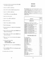
SECTION I
SPECIFICATIONS AND REFERENCE DATA
GENERATOR
DISPLAY PATTERNS
Solid Raster
•
Single Crosshatch;
at
of
Fine Crosshatch
15 lines vertical (0.25
15 lines horizontal (1 scan line)
Bold Crosshatch
8 lines vertical {4
Slines horizontal (16 scan linesl
a
Single Dot
One dot at center of screen
x-v MONITORS
Single Crosshatch
SIZE control
Diagonal Crosshatch
trol
•
at center of
~.
fine line crosshatch
See X-V
See X-V SIZE
Full Screen Lined Raster IX is a maximum
sweep, Y is a maximum
rate
SIZE control
Gray Scale Staircase
level lV
4 level staircase, black
-2-
rate sawtooth
See X-V
1V,
OUTPUT SIGNALS
EXTENDER CABLE
8 foot, extends output connector
venient
MONITOR
ADAPTERS,
MONITOR ADAPTERS
Four (4) supplied (see ADAPTERS
for connections).
FOR RASTER SCAN MONITORS
SYNC OUTPUTS
o to 5V
TTL
FREQUENCY
WIDTH
H
Horizontal
15.625 KH
H
Horizontal Inverted
15.625 KHz
V
Vertical
61.0 Hz
1.0 msec
V
Vertical Inverted
61.0 Hz
1.0 msec
on these signal lines 1 Kn
Minimum monitor input
GUN OUTPUTS
o to 4V TTL Compatible to 4V
R
Red
G
Green
B
Blue
High level adjustable 0
BRIGHTNESS control
Each
may be turned
on or off using GUN CONTROL pushbuttons
Minimum monitor input
A
Mates to most WELLS GARDNER and
ELECTROHOME RASTER SCAN
(6 pin Molex 09-50-7061).
B
Mates to most ELECTROHOME COLOR
X-Y monitors (6 pin Molex 09·50·7061).
C
Mates to many WELLS GARDNER and
ELECTROHOME B/W X·y monitors.
D
Mates to most WELLS GARDNER COLOR
X·Y monitors.
4J1S
OUTPUT CONNECTOR
on these signal lines 15m2
FOR X-V MONITORS
VARI-TRAKER
SIGNAL OUTPUTS
FUNCTIONS
x
to ±4V to ±10V using X-V SIZE control Minimum monitor input resistance 150n
Y
to ±3V to ±7.5V using X-V SIZE control. Minimum monitor input resistance 150n
Located on rear panel. All
are present
on SCAN MODE.
shown on
on
rear panel.
connector Molex Part No,
03-09-3092. Pins Molex Part No. 02·09·2116
(2 extras supplied).
AC and DC
OHMS
RANGE
DC VOLTS
50 volts
input.
GUN OUTPUT
o to +4V TTL
o to +·4 V
Compatible - High level adjustable
BRIGHTNESS control except
DC
quency tone.
Scale)
R
Red
G
Green
B
Blue
AC VOLTS
Each signal may be turned
on or off using GUN CONTROL pushbutton,
Minimum monitor
on these signal lines 150n
-3-
-4-
fre-
250V DC or RMS
DIMENSIONS
10Mn
WEIGHT
2.2 x 6.7
6
/5.6
7
impact,
varies from silent with approx·
300n at the terminals to shrill pitch
at on. Resistances to OAn are discernible as
a tone difference.
ACCESSORIES SUPPLIED
Soft
Four
OPEN CIRCUIT VOLTAGE
15V
MAX OUTPUT CURRENT
16mA
HI
varies from silent with approxi·
mately 2Mn at the terminals to shrill pitch
at 500n. Resistances to 1 Kn are discernible
as tone difference.
OPEN CIRCUIT VOLTAGE
0.7V
MAX OUTPUT CURRENT
250V DC or RMS
VOLTAGE ISOLATION
Generator to VARI·TRAKER - 300V max
GENERAL
500V max to earth ground
105 to 130V RMS, 50/60 Hz 2.5W max
Operating 0° to 50"C
to 75°C
SHOCK &
Meets MIL·T·28800 specifications
Up to 95% (noncondensing)
-5-
-6-
prewired monitor
ABS
SECTION II
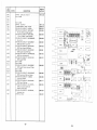
DESCRIPTION OF CONTROLS
1 0 41'44
BRIGHTNESS
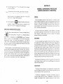
The X-V SIZE control is used in X-V SCAN
MODE only . The co ntrol all ows size adjustment of
all patterns when in X-V o peration . Th e two mark s
at the operating extremes of the control represent
positions in which th e X and V output signal s are
calibrated values . The mar k at minimum adjust ment sets t he X and V output signa ls at X=±4V
and V=±3V. The mark at maxi mum adju stmen t
sets the X and V output signa ls at X =±1OV and
V=±7.5V .
The BRIGHTNESS control is used to adju st the
level of the gun output si gnal s in order to adjus t
brightness of the pattern o n t he mon itor screen .
The contro l has no effect on
m
Gray Scale
since thi s is a ca librated sig na l used to adjust th e
brightn ess of X·V monito rs. Minimum adjustment
represents "0" volts output on the gun control s.
Maximum adju stm ent is approxi mately +4 vo lts on
the gun controls .
TEST
PATTERNS
Mutually interlocked pushbutton switches used to
select the specific pattern d es ired . Th e uppe r row
of patterns are for use with X-V mon itors and sig nals creating these pattern s are o utputed w hen the
SCAN MODE pushbutton is "d epressed" in X-V .
The low er row of pattern s are tor use wi th raste r
scan monitors and signals creating these patte rns
are outputed when the SCAN MODE pushbutton
is in th e "out" position, RASTER .
Ax-!
SCAN
MODE
Sing le push - pu sh pu shbutton used to se lect signal
approp ri ate for either raster scan or X-V monit ors .
... RASTER
GUN CONTROL
PUSH TO ACTIVATE
Single push - push pushbutton sw itches used to
turn on o r turn off the R,G,B sig nals in either X-Y
or raster scan operation . Whe n th e bu tto n is
pushed in, the associat ed si gn a l is prese nt at the
output connector on t he rea r of the instrume nt.
-7 -
SECTION III
OPERATING INSTRUCTIONS
the center portion of the block
PRELIMINARY
VARI-TRAKER
MODE SELECT
pushbutton switch used to select
operation or VARI-TRAKER
the instrument. When V AR I
selected the
portion is
turned off and vice
The
capabilities
the instrument will not operate simultaneously.
When the instrument 1'$ unpacked inspect it for visual
ing accessories should be contained in the lJ''';'''dl'lt<
Slide switch used to select the measurement mode
of the VARI-TRAKER For the two un"
tions
the switch the mode selected is indicated
by the line associated with the mode
visible.
In
VOLTS mode neither "n" line will be
visible. Note that the TEST MODE switch must be
mmI
the VARI-TRAKER to operate.
3. 8 foot extender cable with connectors at both ends
1. Carrying/storage case
2. Line cord
4. Four adapter cables labeled
of the connector which mates with the connector on the 8
5. Two connector shells
6.
banana
The "+" lead indiinputs for DC volts as well as output
ohms measurements. Note that if "0"
a
DC
is applied to the
VARI-TRAKER the tone will be silent.
Standard
VARI-TRAKER
SIGNAL INPUT
OUTPUT
CONNECTOR
recessed compartment on the rear
identified on the rear
are the
present on each pin of the connector. Note
that
will
on the SCAN MODE
selected. For instance in X-Y mode the signal on
the H/X will be "X." In RASTER mode the
the H/X pin will be "H "
The
pins which fit in connector shells
7. Red and black test lead set for use with VARI·TRAKER
GENERAL
To prepare for use, plug the line cord into the
rear panel and the plug into a standard 120V outlet.
the proper
extender cable into the connector on tbe rear panel or the red/black
set into the VARI·TRAKER input
located on the
instrument depending on the intended use.
Set the TEST MODE switch to either TRAKER or GEN
IF USING AS A GENERATOR
1. Select the adapter cable appropriate to the monitor to be
the AOAPTER section of this manual.
2. Be sure the PWR is turned off and connect the
extender cable and to the monitor.
3. Set the SCAN MODE to the type of monitor to be serviced.
4. Turn on the PWR. The back
indicator should illuminate.
5. Proceed with testing.
-8-
-9-
OHMS MEASUREMENTS
desin!d using the VARI-TRAKER
showing indicates LOn or Hln
you have selected VOLTS.
the instrument provides 10MS'l input immeasurement
as
variable
audio tone. Obviously
measurements cannot be made with this method but for field
usually only approximate measurements suffice and other
tone more than outweigh its limitations. With a brief learnaccuracy are easily achievable. The VARIADVANTAGES which make it more
Some of the "n""rn:1OP< are:
keep your concentration on the
in the operation is
fast continuity tests and switch closure tests. Noise or
in switches show up immediately.
Unwanted ripple on DC voltages is identifiable by the sound of the
GETTING THE MOST OUT OF VARI-TRAKER for many more
VARI TRAKER VOLTS mode is used to measure both AC and DC
For DC
only voltages with plus connected to the "+" jack
the tone. Less than 0.2 volts or negative voltages will be silent. The
with
occurs from O.2V to
""It+"""c will have
"warble" associated with the tone of the VARITRAKER The range audio
with voltage magnitude of the
I·TRAKER
AC
200V.
-10-
Two ranges of ohms measurements are provided. The LOn
tended for continuity and very low resistance value
The Hln mode is intended for resistances from soon
be selected for most measurements in circuit
when
Resistances into the high hundred Kn range will have distinctive
tones associated with them. The sound will turn off at
approximately 3Mn.
above
Using the LOn range resistances as low as o.sn can
being different from "0" ohms. Resistances up to about
distinctly characteristic sound. Above 300n the tone turns off. For
that make no sound on the LOn mode the Hln mode should
GETTING THE MOST OUT OF VARI·TRAKER
VARI-TRAKER as a
measuring DC volts in a variety of circuits.
in
where a ripple may be of some concern. If the ripple becomes
more than 2% of the DC
a 60 cycle warble will
appear.
is a good indication that there is a substantial amount of ripple on the supply
and tests for failed filter capacitors or
should be performed.
LOCATING INTERMITTENT PROBLEMS
VARI-TRAKER is designed for quick response. For this
be
very useful tool when looking for an intermittent either
For example, consider a situation in which you are
mittent continuity somewhere in a game. Set the
LOn mode and connect it between the two
points. VARI
TRAKER will present a tone associated with the
between the two
points. Then move wires, vibrate, and otherwise attempt to make the
mittent occur. A change or interruption of audio tone will
alert you
if there is, in fact, an intermittent connection. The fast response
VARI-TRAKER output allows you to detect intermittence that would not
detected with an ordinary
or analog meter.
In repetitive troubleshooting or similar systems, certain
produce characteristic and distinctive sounds from the VARI-TRAKER
put, depending on the
and
associated
-11-
troubleshooting of many circuits
the probe to the various points and
characteristic sounds are there. The human ear is parthe differences in sound which will occur as signals
fortunate that the human
is particularly sensitive to small
and
particularly sensitive to harmonics added to a
For thes!! reasons the VARI-TRAKER can be an extremely
an oscilloscope in many applications.
DC
Detect 2% ripple on power supply
Check power bus voltages
Use for peaking or nulling
Monitor pulse width modulated circuits
Identify voltage polarity
Check AGC circuit operation
Detect low frequency instabilities in amplifiers {motor
Check power supply regulations
Check power supply transient response
OHMS
CAPACITOR CHECKING
I-TRAKER can be used for detection of capacitors in circuits. When
capacitors present, there will be time associated with charging of the
possible to approximate the value of the capacitor by countit takes to
the capacitor until the sound stops
Fast continuity check
test cables, point to point connections, chassis interconnects, ground connections, coax wiring
Detect faulty connections
Check pots for wiper contact over full travel
Remote contact closure detections
Check potentiometer taper
Check for brush bounce
GENERAL
The VAR I-TRAKER output of the ARCADE ANALYZER provides an
meter, An analog response is often more
trends (increasing or decreasing)
response fills this need for
For example, conwhich calls for adjusting to maximum
Using the VARI-TRAKER simply
for the highest frequency
of this type can be achieved within 1/2% of the
with VARI-TRAKER
ADDITIONAL VARI·TRAKER APPLICATIONS
been brief
of ways to use VARI-TRAKER to advanThere are many more ways; there simply isn't room to describe.
Detect intermittent; on volts, ohms, or current by
for
continuities
Use an annunciator monitor
for closure, etc. Audio will appear
"A-B" comparisons when
between
and bad
Signature sound analysis of test points
DIODE CHECK
off go-no go diode check
Distinguish between silicon and germanium (or
junctions
Check
infra-red emitters, and optical coupler
GENERATOR OPERATION
GENERAL
between 60 Hz and 400 Hz line
Trace 100 to 400 Hz audio
audio circuits
Trace line \!l'\,lt""",<
between 110 and 220V AC
Detect Ol)eration of line chopper circuits
full wave vs half wave rectification
SCR control outputs
-12-
The Generator section of the Model 241 ARCADE ANALYZER
signals for servicing and
color and black and white raster
X-V monitors, The patterns available were selected to be compatible
those used in the service literature provided by the monitor
Before beginning to service a monitor, a copy of the manufacturer'S
instructions should be consulted.
-13-
IMPORTANT
instructions for use of patterns
in
monitors is presented; however,
afe interacting and the manufacturers have prescribed an
which
these
Four adapters which mate
most of the monitors currently supplied by
Electrohome and Wells Gardner
provided with the Model 241 Before
connecting to the monitor, the manufacturer's input
should be
the adapter wiring detailed in the ADAPTE R section of this
It none of the
match both connector type and pin-out of
then the operator must make an
Several extra connectors
been provided for this purpose. If additional connectors are needed,
the FIELD REPLACEABLE PARTS LIST in the rear of this manual
In some cases power for the monitor is supplied through the same conthe signals. The Model 241 does not supply power to the monitor.
where power and signals are on the same connector a "Y" adapter is
which plugs into the monitor input, the 241 output and the game
output. The power
made through the connectors from game
are "inserted" into the
Model 241
SECTION IV
RASTER SCAN MONITOR SERVICING
IMPORTANT
Be sure the GENERATOR OPERATION section of
this manual has been reviewed.
GENERAL
The Model 241 RASTER Scan outputs provide separatE! horizontal and
,H
vertical sync signals a to +5 volts (TTL compatible). Both plus
and negative going (V,
are provided
The R ,G and B
signals are separate a to +4 volts (TTL compatible)
which
be
the front panel R,G, B pushbutton,. The
turned on or off
tude can be
from a to +4 volts to control the
using the front panel BRIGHTNESS control For black and white monitors
only one gun signal is required but which
(R
or B)
on the
monitor connections. It is best to activate all GUN CONTROL
RASTER SCAN SETUP
There
several steps and precautions which should be taken when workany Arcade game. They
1. Follow the instructions in the GENERATOR OPERATION
the OPERATING INSTRUCTIONS section of this manual tor
to service a raster scan monitor.
of
IMPORTANT
2. Set the SCAN MODE pushbutton to RASTER and turn the BRIGHTBe sure the Model 241 PWR and the monitor powers are turned OFF
before
to or
from the monitor.
NESS control to minimum.
3. Activate all of the GUN CONTROL switches.
WARNING
4. Select the
2. Many monitors have circuit
connected to one side of the power
The Model 241 is
insulated but the monitor itself can
provide
shock hazard. When servicing such a monitor an isolating
transformer should be used.
3. Be
both the connector ana the pin·out of the Model 241 adapter
matches the monitor you are servicing. If there is any difficulty plug·
check the connector match and for bent pins in
ging in the
either the monitor or instrument connector.
4. If at first
patterns can be
check PWR mode and SCAN
MODE buttons on the Model 241 for proper selection. Then check the
R,G,B buttons to be sure
are activated. Recheck the adapter conin the ADAPTER section).
nections
-14-
G
(Bold Crosshatch pattern.
5. Set PWR to ON.
6. Turn up the BRIGHTNESS control until the pattern appears at
mal brightness. Do not set the
too h
it
defocusing of the CRT.
ADJUSTMENTS SPECIFIC TO RASTER SCAN MONITORS
Adjustment procedures for monitors will vary from monitor to
often even with monitors from the same manufacturer. It is advisable
to use the manufacturer's Service Instructions when n"'F+"F~
to monitors. Presented here is a
-15-
nor.
SECTION V
x-v MONITOR SERVICING
GENERAL
The Model 241 X-Y Scan outputs provide separate X and Y
which are adjustable from X=±4 volts, Y=±3 volts to X=±10 volts, Y~±7.5
volts using the X-V SIZE control. At the control extremes are calibration
marks. When the control is set to these marks, the X and Y
calibrated voltages. See SPECIFICATIONS for details. The R,G and B
which can be
nals (Z) are separate 0 to +4 volts (TTL compatible)
turned on or off using the front panel R,G, B
The
amplitude can be adjusted from 0 to +4 volts to control the pattern
ness on all patterns except the
BRIGHTNESS control.
The
(Gray Scale)
(Gray Scale) pattern is a calibrated
the front panel
pattern used to
adjust black level on the monitor. For black and white monitors only one gun
on the monitor connecsignal is requir,ed but which signal (R ,G or B)
tions. It is best to activate all GUN CONTROL buttons.
X-V SETUP
1. Follow the instructions in the GENERATOR OPERATION section of
the OPERATING INSTRUCTIONS section of this manual for
to service an X-V monitor.
2. Set the SCAN MODE pushbutton to X·Y and turn the BRIGHTNESS
and X·Y SIZE controls to minimum.
3. Activate all of the GUN CONTROL switches.
4. Select the
~
~
(Diagonal Crosshatch) pattern.
5. Set PWR to ON.
6. Turn up the BRIGHTNESS control until the pattern appears at normal
brightness. Do not set the brightness too high as it can cause
of the CRT.
7. Adjust the X-V SIZE control until the pattern covers all but about a
1/2" border around the outside of the CRT. Do NOT
beyond the edges of the CRT because some monitors contain
fuses or circuitry to prevent overdrive and these devices may trip if the
monitor is overdriven.
-18-
scan monitors and the recommended patterns associated
PURITY, STATIC CONVERGENCE, DYNAMIC CON1<1',,,,,,nt. are common to Raster Scan
table lists some of the monitor adjustments for which the
patterns are used.
PATTERNS
Single Crossbar
and
Crosshatch (Bold and Fine)
cushion effect, focus
Static convergence
4.
Single Crossbar, Single Dot
convergence
Fine Crosshatch
Pin cushion distortion is most common on
screen monitors. The
correct amount of compensation should make the vertical and horizontal
crosshatch lines appear as straight and parallel as
If 60 Hz hum is
entering the circuitry, it will produce a horizontal bar
through the
pattern or apparent moving waves through the pattern.
Generally the following control type
scan monitors:
Focus
Vertical Size
Vertical Video Position (often a jumper on PC board)
Focus
Horizontal Hold
Horizontal Video Position
Horizontal Width
correction on
Each of the adjustments are intended for small amounts
the picture. If major corrections are needed
involve
the
CRT Yoke Assembly.
DEFLECTION'SYSTEM
Many abnormalities in a monitor deflection system will show up in a
simple check of the monitor
Always refer to the manufacturer'S
recommendations when
the results of these tests.
selector to the Fine Crosshatch pattern.
the monitor contrast and brightness to display sharp, thin lines
against a black h",'vnrt"ll
3 Note the number of vertical and horizontal lines. The monitor should
15 vertical and 15 horizontal lines.
a stable display of evenly spaced lines to
The Crosshatch pattern
make these
With this pattern displayed, abnormal conditions
such as deflection
pin cushion distortion, and excessive 60 Hz
hum are easily detected.
Vertical size and
should be
to produce even spacing
all horizontal lines. It the adjustments will not permit this, then
may be a vertical deflection nrrlhL,..n
-16-
are present on raster
-17-
HEIGHT, WIDTH, LINEARITY
for monitors will vary from monitor to monitor
often even with monitors from the same manufacturer. It is advisable always
to use the manufacturer's Service Instructions when performing adjustments
to monitors. Presented here is a
review of adjustments normally
on monitors and the recommended patterns associated with each.
PURITY, STATIC CONVE
DYNAMIC CONVERGENCE and
Ich,.,,,,,n'i'c are common to Raster Scan and X-Y monitors
and are presented separately.
table lists some of the monitor adjustments for which the
patterns are used.
PATTERNS
Diagonal Crosshatch, or Single
Crosshatch
2.
Diagonal Crosshatch, or Single
Crosshatch
3. Static convergence
Single Crosshatch, or Diagonal
Crosshatch
4.
Proceed as follows:
1. Set generator output to Diagonal Crosshatch pattern.
as required.
DISPLAY PATTERN USES
The
various
If the X and V deflection
is known
the Diagonal Crosshatch or Single Crosshatch pattern
using the equations presented below. If the ri"'I'It>r'hr,,,
known, then the monitor can be set up
aspect ratio of 4:3 (X:Y) and final sensitivity
the game.
Diagonal Crosshatch, and
Raster
convergence
5. Black level
Gray Scale Staircase
6. Black and white tracking
Scale
Gray Scale Staircase
CENTERING AND POSITIONING
Most monitors contain screwdriver type controls for adjusting centering
and
These controls are generally intended for fine tuning of these
parameters. If gross
must be made, it generally involves movement of the
assembly which can be accomplished in conjunction with
PURITY and CONVERGENCE
II
For
and positioning set the generator to the
(Single
the X-V SIZE for a convenient picture size.
Crosshatch) pattern and
Refer to the manufacturer's literature for
location and adjust for
the lines to cross in the center of the CRT.
-19-
2. Set SIZE control to minimum CAL
pattern now has a calibrated output of
ThEl
Y=±3V.
A) If the monitor
call for
adjust the monitor SIZE controls for a
the screen. Typical lengths on
19"
V=10.5".
B)
14.5" and
If the monitor
call for X=::!:10V and
the X-V SIZE control to the upper CAL
size controls for a picture which
covers the
lengths on a 19" screen are X=14.5" and Y=1O.5".
3. If the monitor specifications call for sensitivities other
Y=±3V or X=±10V, Y=±7.5V the proper sensitivity can
help of the deflection size equations below. To
using the equations proceed as follows.
A} Set the X-Y SIZE control to the minimum CAL
(X=:t4V,
Crosshatch and
Y=±3V). The signals producing the
of X=±4V and V=:+:3V.
Crosshatch are calibrated
B) Determine the desired deflection sensitivity
turer's literature. Measure the "X" and "Y"
using a ruler. Dimensions on a 19"
Y=10.5".
C) To find the length of the "X" size of the pattern
and perform the arithmetic.
X length = Measured width of screen ("S" above)
Using the monitor X size
screen to the "X length" determined
-20-
To find the
arithmetic.
Mfr spec'd sens. ("B" above)
y
Using the monitor Y size
adjust the "Y" line on the
the "Y
determined above.
E) Set the Model 241 to
SECTION VI
"Y" size of the pattern fill in the blanks
(:;:;:3
(Diagonal Crosshatch I and note that
the pattern
square on the screen and that its overall size is the
same
"X" and "Y"
from C) and D) above.
of an X-Y monitor, the Model 241 has
This pattern is a calibrated brightness
by the BRIGHTNESS control. The pattern
()f 1 volt step
in the R,G and B output signals
with "black" (+lV)
and
in 1 volt steps to
The manufacturer's literature should be consulted to be sure
this signal is suitable for the monitor being serviced, however, at this writing
all known monitors
this standard.
'
Normal procedure is to set the drive controls at the center of their rotathe cutoff and common screen control to minimum. Turn up the common screen
until the left hand (black) bar is just visible then back off
until the bar is black,
The cutoff control of whatever color appeared in
the black is left at minimum. Next turn up the other two cutoff controls
similar to what was done with the common screen control. Finally adjust the
dnve controls for neutral white on the "white" (right hand) bar.
GENERAL CONVERGENCE PROCEDURE
(RASTER SCAN AND x-v MONITORS)
GENERAL
Due to the magnetic sensitivity of color monitors, it is desirable
color and alignment adjustments at the site of the permanent
receiver. The light weight and portability of the Model 241 lends
ticularly to "on location" use although it may also be used in the
usually desirable to give the receiver a final touch-up at
tion, if it has been serviced elsewhere.
The service technician who establishes routine
saves himself a great deal of work and time. He
leads. Frequently a slight
is all that
sequence of procedure is recommended.
DEGAUSSING
To remove unwanted stray
To do this, place
at the beginning of all testing or
on the floor about ten feet in front of the monitor.
to the level of the monitor and hold it in a plane parallel
TV tube. Move the coil to within a
of inches of the
maintaining the parallel plane between coil and tube. In a
motion,
pass the coil over the face of the tube a half dozen times. In similar manner
top and (if
the bottom of the
move the coil around the
monitor, always maintaining the
of the coil parallel to the top, sides,
and bottom. Return the coil to the face of the monitor
for
measure, pass the coil over the face of the tube a few times.
Maintaining the parallel
move the coil away from
tube a distance of about ten feet. Turn the coil 90
tube and de-energize the coil.
COLOR PURITY
The purpose of purity
is to compensate for
may exist between the position of the three electronic gun
center of deflection of the tri-color picture tube.
The direction of displacement of the beams is controlled
the purity magnet, while the amount of displacement
field. It might be convenient
strength of the
-21-
-22-
the
the
SECTION VII
entire three gun structure with respect to
screen in the color picture tube.
each of the beams to strike its respective
ADAPTERS
SUPPLIED ADAPTERS
made with only one gun in operation, while the
biased
cut-off. In this way we can determine if the
the proper phosphor dots to produce a pure color
the red beam. Impurities are more readily observed
blue or green screens. A portion of the red
green
will illuminate them and conIf th is condition occurs, color impurity results. A pure
of the static convergence magnets on the
the purity magnet adjustment tabs, the deflecBefore beginning purity or convergence
all picture centering, size, linearity, and focus
STATIC CONVERGENCE
using one or more pairs of ring
of the CRT. The rings are adjusted to converge the
in the center portion of the CRT screen. This is most
a
Crosshatch or
a
Four adapter harnesses are
with the Model 241 ARCADE
ANALYZER. These adapters are compatible with nearly all Electrohome and
Wells Gardner and a number of other manufacturers' X-V and Raster Scan
monitors used in arcade games.
It does not
The Model 241 supplies only
to the monitor under
and
supply operating power. Most raster scan monitors have separate
power connectors and therefore only a
connector to match the
input connector of the monitor is
A number of X·Y monitors,
however, use the same connector for both
and power. Thfl adapter
therefore must connect POWflf from thfl game and allow
to bfl
from the Model 241. The
for these monitors need 3 connectors (1 to
the game, 1 to the monitor, 1 to the Model 241).
The following table lists the particulars on the four
the Model 241 along with a partial list of the monitors it
Single Dot.
Each manufacturer has their own method of adjusting purity and since it is
often involving movement of the yoke, the manuthe
safe way of assuring good results. For this
procedure we might give could be misleading.
DYNAMIC CONVERGENCE
converges the
green, and blue beams around the outer
On most arcade game monitors this is performed
of the yoke with respect to the CRT neck and fixing it in
for these adjustments so no
procedure.
ADAPTER A
Used on raster scan monitors only.
Monitor Connector: 6 terminal Molex
"PIN OF
MOLEX
CONNECTOR
WELLS GARDNER
SCHEMATIC
NUMBERING
1
6
5
2
3
4
5
6
SIGNAL
Horizontal
(H
Vertical Sync (V)
GND
Blue Gun
Green Gun
Red Gun
4
3
2
1
"On manufacturer's schematic, pin
molded on the Molex connector.
is
Typical Monitors using Adapter A
Wells Gardner 19K4901, 19K4906, 19K4951, 19K4956
Electrohome G07 Series Monitors
-23-
with
with.
-24-
numbers
ADAPTER D
ADAPTER B
For use with color KY monitors.
color X-Y monitors.
Game/Monitor Connectors: Amp "Mate and Lock" 15 pins
Molex
~PIN
OF
MOLEX
CONNECTOR
WELLS GARDNER
SCHEMATIC
NUMBERING
PIN OF
CONNECTOR
SIGNAL
SIGNAL
Red Gun
Green Gun
Blue Gun
Ground
N.C.
N.C.
Horizontal (X)
Vertical (Y)
N.C.
N.C.
N.C.
N.C.
Power
Power Ground
Power
1
6
5
4
3
2
2
5
6
Blue Gun
Green Gun
Red Gun
GND
Vertical (Y)
Horizontal (X)
1
2
3
4
5
6
7
8
schematic, pin numbering is reverse of numbers
molded on the Molex connector.
9
10
11
12
13
14
15
ADAPTER
Used on black and white X-Y monitors only.
Typical Monitors using Adapter D
Wells Gardner Color X-Y Model 19K6103
Game/Monitor Connectors: 12 pin AMP "Mate and Lock"
PIN OF
AMP CONNECTOR
SIGNAL
1
2
3
4
5
6
Z (Red Gun)
Vertical (Y)
Horizontal (X)
Power Ground
Signal Ground
Signal Ground
Power
Signal Ground
8
9
10
11
12
Monitors
~wer
Power
Power Ground
Power
C
Gardner 19V2000
Electrohome G05 Series Monitors
-25-
-26-
SECTION VIII
MAKING YOUR OWN ADAPTERS
The adapters p ro vid ed with the Model 241 cover most of the monitors in
service in arcade games today . If , however, it is necessary to service a game
co nta ining a monitor o ther t han one of t hose compatible with the supplied
adapt e rs, it is not difficul t to make your own adapter . The Model 241 is
su pp lied with 2 extra connecto rs compatible with the output plug on the
instrument and extender cable .
SPECIAL ADAPTE
DESCRIPTION
NUMBER REQ'D
1
9 Pin Connector f or connection to Model 241
6
Termina ls fo r connector
Connector for connection to Monitor
The key to successful adapter construction is some initial care to be sure
you are connecting the co rrect . signal to the co rrect pin of the monitor
con nector . We suggest you use the ch art below and fi ll in the blanks , then
ma ke the cable accordi ng to the chart.
Term ina ls for connector
On many X·Y monitors, both signal and power are supplied to the monitor
through the same connector . Th e Model 241 does NOT supply power so it
will be necessary to make a cable t hat plugs into both the monitor and the
game output connect o r (to t he mon itor ) as well as the Model 241 . The
object ive is to supply monitor power tro m the game and signals to the monito r fr om the Mod el 241 so a " Y" kind of adapter t hat plugs into all three
connectio ns will be necessar y. Most raster scan mon itors have signal and
power con nections separated into two d iff erent connectors so it is only necessary t o connect into the si gnal co nnector .
Connector for connection to Game
IF REQUIRED FOR POWE R
Term inals for connect or
MODEL 241 9 PIN
CONNECTOR
PIN
SIGNAL
DESCRIPTION
Step By Step Procedure :
1. F ill out the chart below .
2 . Obta in the proper connecto rs and compatible terminals. The parts list
in th is manual contain s a list of connectors typ ically used in arcade
games and most are readily avai lable from arcade gam e service parts
su p pl ie rs .
3 . Usi ng st randed # 18 to # 2 2 insul at ed wire , make the connections called
fo r in t he chart .
4 . Check your wor k then plug it in and service the game .
1
V
Vertical (X -V)
2
3
V
Inverted Vertical Sync
GND
Ground
4
HIX
Horizonta l (X ·V)
5
6
V
Normal Vertical Syn c
H
I nverted Hor izontal Sync
7
R/ Z
Red Gu n
8
GIZ
BIZ
Green Gun
Horizonta l Sy nc (raster scan)
9
Blue Gun
VIEWED FROM
REAR OF
INSTRUMENT
-27-
- 28-
SECTION IX
MAINTENANCE AND CALIBRATION
"ORK CHART
Your Model 241 ARCADE ANALYZER has been constructed
the
components and
that the electronic
has to offer
It has been designed for long reliable service as indicated
(1
warranty.
MANUFACTURER AND PART NUMBER
Should difficulty be encountered with your instrument, The Hickok Electrical Instrument Co. maintains complete facilities for reliable and
service of our products.
A troubleshooting procedure is not
in this manual. The
enced electronic technician can easily interpret the Schematic and Parts
Location diagrams for routine troubleshooting.
MONITOR CONNECTOR
[SIGNALS FROM 241, POWER
FROM GAME CONNECTOR
(IF REQUIRED
WIRE
COLOR
PIN
GAME CONNECTOR
[POWER TO MONITOR
(IF REQUIRED)]
POWER DESC.
WIRE
COLOR
PIN
Special effort has been made to design the instrument around components
that are readily available in electronic distribution. In
the calibration of the unit has been developed using
purpose test equipment
commonly found in most repair facilities. For these reasons your Model 241
can easily be checked or repaired by competent service personnel.
CAUTION
There is exposed power line voltage present inside the
Model .241 whenever the unit is
in
of the ON-OFF switch position. Always
unit from the power source when
repairing the unit.
To calibrate the Model 241 you will need:
AC accuracy ±1
Digital Multimeter
15 MHz Oscilloscope
200mV DC Voltage Source
To accomplish the calibration, perform the
adjustments are in the Parts Location
1. Plug the unit into 115 volt
60 Hz power source and tum it on.
2. Set the front panel controls as follows:
TEST MODE - GEN.
SCAN MODE - X-Y
Minimum CAL position
X-V SIZE
TEST PATTERN - Diagonal Crosshatch
GUN CONTROL
All activated
BRIGHTNESS - Maximum
-29-
-30-
of
SECTION X
set
AC volts monitor from Pin 3 (GND)
Pin 4 (Xl
3.
4.
2.22:l:0.0lV AC.
(R336)
5. Monitor from Pin 3
y
6.
of the OUTPUT connector to Pin 1 IY).
(R230) for 1.65±O.OlV AC.
7. Set the X·Y SIZE control to the maximum CAL position.
8. Again
PARTS LIST
When
parts be sure to
the Hickok part number
indicated in the DESCRIPTION
models. Also include the model
mum billing is $50.00. Orders
prepaid if ''''t'ornn.::''>1
postage and handling.
from Pin 3 to Pin 4.
cal (R229) for 5.55±0.OlV AC.
9.
10. Monitor
DESCRIPTION
CONN
Pin 1
for 4.17±O.OlV AC.
1L
12. Select the
Scale pattern.
Pin 3 (GND) and Pin 7 (R/Z) of the OUT·
13. Connect the
PUT connector
14.
the White Level pot (R128) to obtain 4.00V±O.05V for the
step on the staircase
15.
lowest
the Black Level pot (R 127) to obtain 1.00V±O.05V for the
the staircase.
16.
interact) until the voltages are
17. Set
front panel controls
follows:
TEST MODE TRAKER
VARI·TRAKER MODE SELECT VOLTS
18. Apply 200mV DC plus
19.
SOUND CAL
by the
of the VARI·TRAKER input
so that a slow ticking sound is emitted
VARI~TRAKER.
This completes
of
instrument.
FIELD REPLACEABLE
CAP: decorator, molded . . . . .
CABLE ASSEMBLY: extender
CABLE ASSEMBLY adapter "AU
CABLE ASSEMBLY: adapter
CABLE ASSEMBLY
"C"
CABLE ASSEMBLY. adapter "0"
CASE: molded, top
CASE: molded, bottom
CASE: carrying. vinvt (CC·S)
CORD: line
KNOB: round .
KNOB: square
LEAD SET: banana plug to
NAMEPLATE. front panel,
NAMEPLATE' front panel,
NAMEPLATE front panel,
PANEL: front
PANEL: upper left
PANEL ASSEMBLY: side
PANEL ASSEMBLY
-31-
prod
upper
lower
upper
(includes
rear
-32-
REF.
DESIG.
N
HICKOK
PART No.
DESCRIPTION
REF.
DESIG.
CR106
RVICE PARTS
CAPACITOR, FIXED, ALUMINUM ELECTRO·
LYTIC 100 /.Lf, 35 volts
CAPACITOR, FIXED, ALUMINUM ELECTRO·
LYTIC 10
35 volts
CAPACITOR, FIXED, CERAMIC:
type,
50
C101
Cl02
CAPACITOR, FIXED, CERAMIC disc type,
3085·592
3085·580
3110·371
3111-513
IXED, CERAMIC: disc type,
disc type,
3111·512
disc type,
3111-515
disc type,
3111-514
disc type,
3110·332
disc type,
3111·524
FIXED, CERAMIC: disc type,
3111·518
3103·187
3085·577
CR107
CRll1
CR201
CR202
CR203
CR204
CR205
CR206
CR207
DS101
Fl01
Jl0l
J201
J202
J203
J204
0101
0102
Rl02
Rl05
Rl06
3103·184
diode
3870·229
R107
Rl08
Rl09
Rlio
R111
R112
R113
R114
Rll5
Rll6
Rl17
-33-
SEMICONDUCTOR
lN914
Same as CR 106
Same as CR101
SEMICONDUCTOR
lN57298,5,1
Same as CR202
SEM ICON DUCTOR
Same as CR 106
Same as CR 106
Same as CR202
LAMP, LED: red
FUSE SLO·8LO, 1/4
CONNECTOR
CONNECTOR 6
Same as .1202
Same as J201
TRANSISTOR
Same as 0101
2N3904
thru
0105
0106
0107
0108
0109
0201
Rl01
Rl03
Rl04
3085·582
DESCR IPTION
NOTES
TRANSISTOR
2N3906
Same as 0101
Same as 0106
Same as 0101
Same as 0106
RESISTOR, FIXED. DEPOSITED
30K ohms,
1/4 waU
RESISTOR, FIXED. DEPOSITED
15K ohms,
1/4 watt
Not used
RESISTOR, FIXED, COMPOSITION
10 megohms,
1/4 watt
Same as R 102
RESISTOR, FIXED, DEPOSITED L " " , n l J l \ l
75 ohms, 5%, 1/4 watt
RESISTOR, FIXED, DEPOSITED
10K ohms,
1/4 watt
Same as R107
RESISTOR, FIXED, DEPOSITED
100 ohms,
1/4
Same as R107
RESISTOR, FIXED, DEPOSITED
lK ohms,
1/4
Same as Rl09
Same as R 107
Same as Rlll
Same as R107
Same as Rl09
Same as R111
-34-
HICKOK
PART NO.
HICKOK
PART NO.
REF.
DESIG.
R202
R203
18470·105
R204
18470·104
18470·223
16925·820
16925-819
18470·274
18470·393
18470362
18470-433
18470·394
18470·753
18470·564
R205
R206
R207
A-H
R208
R209
R210
R211
R212
R213
thru
R215
R216
R217
R218
R2l9
R220
R221
R222
R223
R224
R225
18470-473
R226
R227
R228A
R228B
R229
18470·154
18411-511
R230
R231
R232
R233
S101
S102
S108
thru
5110
NOTES
DESCRIPTION
Same as R201
RESISTOR, PTC: high voltage current limiter,
1 K ohms, 40"'(, at 25"C
temperatur e
coefficient
RESISTOR, VARIABLE: linear taper,
25K ohms, 20%
Not used
RESISTOR, FIXED, DEPOSITED CARBON
430K ohms, 5%, 1/4 watt
RESISTOR NETWORK: thick film
Not used
Not used
Same as R104
Same as R122
RESISTOR, FIXED, DEPOSITED CARBON:
200K ohms, 5%, 1/4 watt
Not used
RESISTOR, FIXED, DEPOSITED CARBON
62K ohms, 5%,114 watt
Same as R124
Not used
Same as Rl07
Same as Rl09
RESISTOR, FIXED, DEPOSITED CARBON:
1.3K ohms, 5%, 1/4 watt
Not used
RESISTOR, FIXED, DEPOSITED CARBON
6.8K ohms, 5%, 1/4 watt
RESISTOR, FIXED, DEPOSITED CARBON
2.7K ohms, 5%,114 watt
RESISTOR, VARIABLE horizontal mounting,
25K ohms, 20%
RESISTOR, VARIABLE: horizontal mounting,
50K ohms, 20%, 0.1 watt
RESISTOR, FIXED, DEPOSITED CARBON
9.1 K ohms, 5%, 1/4 watt
RESISTOR, VARIABLE' linear taper dual,
25K ohms, 20%
Same as R228A
RESISTOR VARIABLE horizontal mounting,
5K ohms, 20%
Same as R226
Same as R227
Not used
Same as R229
SWITCH: pushbutton,5 station
Same as S101
Same as 5101
-36-
HICKOK
PART NO.
1868U,9
16925·965
18470434
16950·29
18470·204
18470~23
18470·132
18470·682
1l3470·272
16925-847
16925·788
18470·912
16925·964
16925-846
19910·297
REF.
OESIG.
S103
S104
theu
S107
S111
S201
n01
Ul01
U102
U103
U104
U105
U106
Ul07
Ul08
U109
U110
U111
U112
U113
U114
U115
U116
7
U201
U202
Yl01
NOTES
HICKOK
PART NO.
DESCRIPTION
SWITCH. pushbutton, 6
S103
·
S103
SWITCH
4p 3t
...
TRANSFORMER. power, 115VAC
·.
INTEGRATED CIRCUIT: LM324N
·
INTEGRATED CIRCUIT: MC78L15CP,
15 volts, 100mA, voltage regulator
INTEGRATED CIRCUIT: MC79L 15CP,
·
-15 volts, 100mA, voltage regulator
INTEGRATED CIRCUIT: MC14069UBCP,
hex
INTEGRATED CIRCUIT: MC14520BCP,
CMOS, dual binary up counter
INTEGRATED CIRCUIT: MC14012BCP,
CMOS, dual 4-input NAND gate
INTEGRATED CIRCUIT: MC14001BCP,
CMOS, quad 2-input NOR gate
INTEGRATED CIRCUIT: MC14049UBCP,
CMOS, hex inverter buffer
INTEGRATED CIRCUIT: MC14011BCP, ·
CMOS, quad NAND
Same
U106
Same
U104
INTEGRATED CIRCUIT: MC14070BCP, ·
CMOS, quad 2-input exclusive OR gate
Same
U105
Same
U106
INTEGRATED CIRCUIT: MC140161BCP,
CMOS, syn prog., 4·bit count binary
INTEGRATED CIRCUIT: TL084CN, · .
quad bifet OP-AMP
INTEGRATED CIRCUIT: MC14013BCP,
CMOS, dual D flip flop
INTEGRATED CIRCUIT: 1CL7611CPA,
CMOS,
power operational
amplifier single supply
INTEGRATED CIRCUIT: ICM75551PA,
low power timer
CRYSTAL: 4 MHz
. . · ..
-37-
....
19910-296
· ..
19911-232
20800-521
9800-270
9800-265
.
. · ..
9800-194
9800-246
..
9800-281
9800-236
9800-96
·.
9800-162
. ·.
9800-131
.
9800-226
9800-268
9800-296
·.
9800-111
·.
9800-245
·.
9800-254
..
3800-447
-38-
-39-