1
SERIES
Installation and
Servicing Instructions
Type C Boilers
G.C.N: 47-116-23
41-116-08
LEAVE THESE INSTRUCTIONS
WITH THE END-USER
Country of destination: GB
TABLE OF CONTENTS
1.
GENERAL INFORMATION
1.1.
1.2.
6.
SERVICING INSTRUCTIONS
6.1.
6.2.
GENERAL INFORMATION
OVERALL VIEW
6.2.1.
2.
INSTALLATION
2.1.
2.2.
2.3.
2.4.
2.5.
2.6.
2.7.
2.8.
2.9.
2.10.
2.10.1.
2.10.2.
2.10.3.
2.10.4.
2.10.5.
2.11.
2.12.
6.3.
6.3.1.
6.3.2.
6.3.3.
6.3.4.
REFERENCE STANDARDS
SITING THE APPLIANCE
OVERALL DIMENSIONS
MINIMUM CLEARANCES
MOUNTING THE APPLIANCE
ELECTRICAL CONNECTION
GAS CONNECTION
WATER CONNECTIONS
FLUE CONNECTIONS
ACCESSORY CONNECTION
ROOM THERMOSTAT CONNECTION
REMOTE CONTROL CONNECTION
ACCESSORY CONNECTION TERMINAL BLOCK
CYLINDER TEMPERATURE PROBE CONNECTION
REMOTE CONTROL TERMINAL BLOCK AND
CYLINDER PROBE
ELECTRICAL DIAGRAM
WATER CIRCUIT DIAGRAMS
6.3.5.
6.3.6.
6.3.7.
6.3.8.
6.4.
6.5.
6.5.1.
6.5.2.
6.5.3.
6.5.4.
6.5.5.
6.5.6.
3.
COMMISSIONING
3.1.
3.2.
3.3.
3.4.
3.5.
3.6.
3.6.1.
3.6.2.
3.6.3.
3.6.4.
3.6.5.
3.6.6.
3.6.7.
3.7.
3.8.
3.9.
3.10.
INITIAL PROCEDURES
REMOVING THE CASING
CONTROL PANEL
INITIAL START-UP
DISPLAY: MESSAGES SHOWN DURING
NORMAL OPERATION
OPERATING PARAMETERS
REGULATION MENU TABLE
SETTINGS DISPLAY
COMFORT KEY
GAS REGULATION CHECK
IGNITION DELAY
ADJUSTING THE MAXIMUM HEATING POWER
SOFT LIGHT ADJUSTMENT
CHANGING THE TYPE OF GAS
BOILER SAFETY SYSTEMS
COMBUSTION ANALYSIS
DRAINING
6.5.7.
6.5.8.
6.5.9.
6.5.10.
6.5.11.
6.5.12.
6.6.
6.6.1.
6.6.2.
6.6.3.
7.
FAULT FINDING
7.1
8.
ZONE VALVES
5.
MAINTENANCE
9.
5.1.
5.2.
5.3.
5.4.
2
GENERAL REMARKS
CLEANING THE PRIMARY EXCHANGER
CLEANING THE CONDENSATE TRAP
OPERATIONAL TES
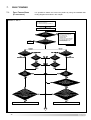
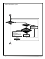
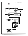
FAULT FINDING GUIDE (FLOW-CHARTS)
SHORT SPARES PARTS LIST
8.1.
8.2.
4.
REPLACEMENT OF PARTS
TO GAIN GENERAL ACCESS
REMOVING THE SIDE PANELS
ACCESS TO THE COMBUSTION CHAMBER
REMOVING THE FAN
REMOVING THE BURNER
REMOVING THE ELECTRODES
REMOVING THE COMBUSTION CHAMBER
INSPECTION PANEL
REMOVING THE HEAT EXCHANGER
REMOVING THE CONDENSATE COLLECTOR
REMOVING THE CONDENSATE TRAP
REMOVING THE INJECTOR
REMOVING THE GAS VALVE
ACCESS TO THE WATER CIRCUIT
REMOVING THE D.H.W.
(SECONDARY)EXCHANGER
REMOVING THE SAFETY VALVE
REMOVING THE AUTOMATIC AIR VENT
REMOVING THE PUMP PRESSURE SWITCH
REMOVING THE DIVERTER VALVE ACTUATOR
(MFFI ONLY)
REMOVING THE D.H.W. FLOW SWITCH
(MFFI ONLY)
REMOVING THE PUMP
REMOVING THE PRESSURE GAUGE
REMOVING THE EXPANSION VESSEL
REMOVING THE D.H.W. TEMPERATURE
PROBE (N.T.C. - MFFI ONLY)
REMOVING THE C.H. FLOW TEMPERATURE
PROBE (N.T.C.)
REMOVING THE C.H. RETURN TEMPERATURE
PROBE (N.T.C.)
ACCESS TO THE CONTROL SYSTEM
CHECKING THE FUSES
REMOVING THE PRINTED CIRCUIT BOARDS
REMOVING THE TIME CLOCK
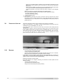
ecoCOMBI 27 MFFI
ecoSYSTEM 27 RFFI
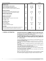
TECHNICAL INFORMATION
1. GENERAL
INFORMATION
This manual is an integral and essential part of the product. It should be kept with the
appliance so that it can be consulted by the user and our authorised personnel.
Please carefully read the instructions and notices about the unit contained in this
manual, as they provide important information regarding the safe installation, use and
maintenance of the product.
For operating instructions please consult the separate End User Manual.
1.1.
GENERAL INFORMATION
Read the instructions and recommendations in these Installation Instructions carefully
to ensure proper installation, use and maintenance of the appliance.
Keep this manual in a safe place. You may need it for your own reference while
Servicing Technicians or your installer may need to consult it in the future.
This is a combined appliance for the production of Central Heating (C.H.) and
Domestic Hot Water (D.H.W.).
This appliance must be used only for the purpose for which it is designed.
The manufacturer declines all liability for damage caused by improper or negligent
use.
No asbestos or other hazardous materials have been used in the fabrication of this
product.
Before connecting the appliance, check that the information shown on the data plate
and the table on the last page comply with the electric, water and gas supply of the
property. You will find the data plate on the reverse of the control panel.
The gas with which this appliance operates is also shown on the label at the bottom of
the boiler.
Do not install this appliance in a damp environment or close to equipment which
spray water or other liquids.
Do not place objects on the appliance.
Do not allow children or inexperienced persons to use the appliance without
supervision.
If you smell gas in the room, do not turn electrical switches on or off, use the
telephone or any other object which might cause sparks.
Open doors and windows immediately to ventilate the room.
Shut the gas mains tap (on the gas meter) or the valve of the gas cylinder and call
your Gas Supplier immediately.
If you are going away for a long period of time, remember to shut the mains gas tap or
the gas cylinder valve.
Always disconnect the appliance either by unplugging it from the mains or turning off
the mains switch before cleaning the appliance or carrying out maintenance.
In the case of faults or failure, switch off the appliance and turn off the gas tap. Do
not tamper with the appliance.
For repairs, call your local Service Agent and request the use of original spare parts.
For in-guarantee repairs contact MTS (GB) Limite1d.
3
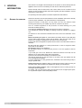
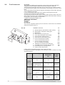
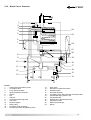
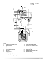
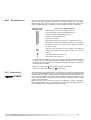
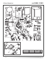
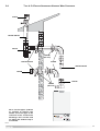
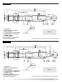
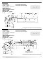
1.2.
OVERALL VIEW
27 MFFI
1
2
3
4
27 RFFI
1
2
24
5
6
4
24
5
6
7
23
8
9
23
22
21
8
9
20
10
11
3
12
10
11
12
7
21
13 14 15 16 17 18 19
FIG. 1.0
LEGEND:
1. Flue connector
2. Air release valve
3. Pump pressure switch
4. Central Heating flow temperature probe
5. Mixer
6. Ignition and detection electrode
7. Fan
8. Silencer
9. Central Heating return temperature probe
10. Condensate trap (tube)
11. Condensate trap
12. Safety valve (3 bar)
13. Domestic Hot Water temperature probe
14. Automatic by-pass
15. Secondary heat exchanger
16. Gas valve
17. Diverter valve
18. Domestic Hot Water flow switch
19. Drain valve
20. Circulation pump with automatic air release valve
21. Expansion vessel
22. Condensate collector
23. Combustion chamber inspection hatch
24. Main heat exchanger (aluminium)
4
22
20
16
19
2. INSTALLATION
2.1.
REFERENCE STANDARDS
The technical information and instructions provided herein below are intended for the
installer so that the unit may be installed correctly and safely.
The installation and initial start up of the boiler must be by a CORGI Approved Installer in
compliance with the installation standards currently in effect, as well as with any and all local
health and safety standards i.e.. CORGI .
This appliance must be installed by a competent installer in accordance with current
Gas Safety Regulations (Installation & Use) 1996.
The installation of this appliance must be in accordance with the relevant requirements of
the current Gas Safety Regulations (Installation & Use) 1996, current Building Regulations,
the current I.E.E. Wiring Regulations, current Water Regulations/ Byelaws, in Scotland in
accordance with the Building Standards (Scotland - Consolidated) Regulations and Health
and Safety document No. 635 “Electricity at work regs. 1989” and in Ireland the local
Building Regulations (IE).
C.O.S.H.H
Materials used in the manufacture of this appliance are non-hazardous and no special
precautions are required when servicing.
Gas installations
Boilers of rated input
not exceeding 60 kW
BS 6891
1988
BS 6798
1987
BS 5449
1990
Flues
BS 5546
BS 5440-1
1990
1990
Air supply
BS 5440-2
1989
Treatment of water in domestic
hot water central heating systems
BS 7593
1992
Forced circulation hot
water system
Installation of gas hot water
supplies for domestic purposes
( 2nd family gases)
2.2.
SITING THE APPLIANCE
I.E.E. wiring regulations
Specification for expansion
vessels
BS 7671
1992
BS 4814
1990
Installation of L.P.G.
BS 5482
1994
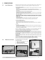
Installation should also comply with the following British Standard Codes of Practice:The
appliance may be installed in any room or indoor area, although particular attention is
drawn to the requirements of the current I.E.E. Wiring Regulations, and in Scotland,
the electrical provisions of the Building Regulations applicable in Scotland, with
respect to the installation of the combined appliance in a room containing a bath or
shower.
Where a room-sealed appliance is installed in a room containing a bath or
shower the boiler and any electrical switch or appliance control, utilising mains
electricity should be situated so that it cannot be touched by a person using the
bath or shower.
The location must permit adequate space for servicing and air circulation around the
appliance as indicated in paragraph 2.4.
The location must permit the provision of an adequate flue and termination.
For unusual locations special procedures may be necessary.
BS 6798-1987 gives detailed guidance on this aspect.
A compartment used to enclose the appliance must be designed specifically for this
purpose. No specific ventilation requirements are needed for an installation within a
cupboard.
This appliance is not suitable for outdoor installation.
The type C appliances (in which the combustion circuit, air vent intake and
combustion chamber are air-tight with respect to the room in which the
appliance is installed) can be installed in any type of room.
There are no limitations with respect to ventilation and the volume of the room itself.
The boiler must be installed on a solid, permanent wall to prevent access to the
electrical parts (when live) through the aperture on the back frame.
5
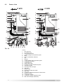
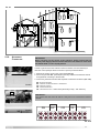
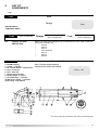
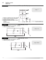
2.3.
OVERALL DIMENSIONS
27 MFFI
FIG. 2.0
700
100
F
27 RFFI
8
305
88
400
LEGEND:
A = Central Heating Flow (3/4”)
B = Domestic Hot Water Outlet (1/2”)
C = Gas Inlet (3/4”)
D = Domestic Cold Water Inlet (1/2”)
E = Central Heating Return (3/4”)
F = Condensate discharge
100
132
132
F
FIG. 2.1
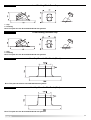
2.4.
MINIMUM CLEARANCES
In order to allow for access to the interior of the boiler for maintenance purposes, the boiler
must be installed in compliance with the clearance requirements indicated in the diagram
below.
27 MFFI
27 RFFI
300
300
FIG. 2.2
*
*
300
450
6
2.5. MOUNTING THE
APPLIANCE
Fasten the boiler in place using the template and anchors supplied with the unit. It is
highly recommended that a spirit level be used to position the boiler so that it is
perfectly level.
For additional information, please consult the instructions contained in the connection
kit and the flue kit.
2.6. ELECTRICAL CONNECTION
For safety purposes, have a competent person carefully check the electrical system in
the property, as the manufacturer will not be held liable for damage caused by the
failure to earth the appliance properly or by anomalies in the supply of power. Make
sure that the residential electrical system is adequate for the maximum power
absorbed by the unit, which is indicated on the rating plate. In addition, check that the
section of cabling is appropriate for the power absorbed by the boiler.
The boiler operates with alternating current, as indicated in the technical data table
(1.2), where the maximum absorbed power is also indicated. Make sure that the
connections for the neutral and live wires correspond to the indications in the diagram.
The appliance electrical connections are situated on the reverse of the control panel
(see the servicing manual for further information)
FIG. 2.3
IMPORTANT!
In the event that the power supply cable must be changed, replace it with one with the
same specifications. Make the connections to the terminal board located within the
control panel, as follows:
- The yellow-green wire should be connected to the terminal marked with the earth
symbol; make sure to re-use the ferrule mounted on the other supply cord;
- The blue wire should be connected to the terminal marked “N”;
- The brown wire should be connected to the terminal marked “L”.
Note: The diagrams for the electrical system are indicated in section 2.11.
Warning, this appliance must be earthed.
External wiring to the appliance must be carried out by a qualified technician and be in
accordance with the current I.E.E. Regulations and applicable local regulations. This
range of boilers are supplied for connection to a 230 V~ 50 Hz supply.
The supply must be fused at 3 A.
The method of connection to the electricity supply must facilitate complete electrical
isolation of the appliance, by the use of a fused double pole isolator having a contact
separation of at least 3 mm in all poles or alternatively, by means of a 3 A fused three
pin plug and unswitched shuttered socket outlet both complying with BS 1363.
The point of connection to the Electricity supply must be readily accessible and
adjacent to the appliance unless the appliance is installed in a bathroom when this
must be sited outside the bathroom.
2.7.
GAS CONNECTION
The local gas region contractor connects the gas meter to the service pipe.
If the gas supply for the boiler serves other appliances ensure that an adequate
supply is available both to the boiler and the other appliances when they are in use at
the same time.
Pipe work must be of an adequate size. It should not be less than 22mm to within 1
metre of the boiler.
7
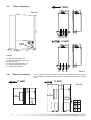
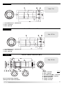
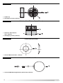
2.8.
WATER CONNECTIONS
VIEW OF THE BOILER CONNECTIONS
27 RFFI
27 MFFI
I
I
B
A
H
C
D
E
J
C
A
E
J
H
FIG. 2.4
Legend:
A
B
C
D
=
=
=
=
Central Heating Flow
Domestic Hot Water Outlet
Gas Inlet
Domestic Cold Water Inlet
E
H
I
J
=
=
=
=
Central Heating Return
Condensate discharge
Safety valve discharge
Drain valve
Central Heating
Detailed recommendations are given in BS 6798:1987 and BS 5449-1:1990, the
following notes are given for general guidance.
PIPE WORK:
Copper tubing to BS EN 1057:1996 is recommended for water pipes. Jointing
should be either with capillary soldered or compression fittings.
Where possible pipes should have a gradient to ensure air is carried naturally to air
release points and water flows naturally to drain taps.
The appliance has a built-in automatic air release valve, however it should be
ensured as far as possible that the appliance heat exchanger is not a natural
collecting point for air.
Except where providing useful heat, pipes should be insulated to prevent heat loss
and avoid freezing.
Particular attention should be paid to pipes passing through ventilated spaces in
roofs and under floors.
BY-PASS:
The appliance includes an automatic by-pass valve, which protects the main heat
exchanger in case of reduced or interrupted water circulation through the heating
system, due to the closing of thermostatic valves or cock-type valves within the
system.
SYSTEM DESIGN:
This boiler is suitable only for sealed systems.
DRAIN COCKS:
These must be located in accessible positions to permit the draining of the whole
system. The taps must be at least 15mm nominal size and manufactured in
accordance with BS 2870:1980.
SAFETY VALVE DISCHARGE:
The discharge should terminate facing downwards on the exterior of the building in
a position where discharging (possibly boiling water & steam) will not create danger
or nuisance, but in an easily visible position, and not cause damage to electrical
components and wiring.
The discharge must not be over an entrance or a window or any other type of
public access.
CONDENSATE DISCHARGE:
The condensate discharge hose from the boiler must be inserted by at least 50 mm
into a suitable acid resistant pipe - e.g. plastic waste or overflow pipe. The
condensate discharge pipe must have a continuous fall and preferably be installed
and terminated within the building to prevent freezing.
The discharge pipe must be terminated in a suitable position:
8
i) Connecting in to an internal soil stack (at least 450 mm above the invert of the
stack). A trap giving a water seal of at least 75 mm must be incorporated into
the pipe run , there also must be an air break upstream of the trap.
ii) Connecting into the waste system of the building such as a washing machine or
sink. The connection must be upstream of the washing machine/sink (If the
connection is down stream of the waste trap then an additional trap giving a
minimum water seal of 75 mm and an air break must be incorporated in the
pipe run, as above.
iii) Terminating into a gully, below the grid level but above the water level.
iv) Into a soakway.
NOTE: If any condensate pipe work is to be installed externally, then it should be
kept to a minimum and be insulated with a waterproof insulation and have a
continuous fall.
AIR RELEASE POINTS:
These must be fitted at all high points where air naturally collects and must be sited
to facilitate complete filling of the system.
The appliance has an integral sealed expansion vessel to accommodate the
increase of water value when the system is heated.
It can accept up to 7 l (1.5 gal) of expansion water. If the heating circuit has an
unusually high water content, calculate the total expansion and add an additional
sealed expansion vessel with adequate capacity.
MAINS WATER FEED - CENTRAL HEATING:
There must be no direct connection to the mains water supply even through a nonreturn valve, without the approval of the Local Water Authority.
FILLING:
A temporary method for initially filling the system and replacing lost water during
servicing and initial filling (in accordance with Water Supply Byelaw 14), is provided
as an integral part of the connection kit (see FIG. 2.5). The flexible hose must be
removed once the system has been filled. The D.H.W. inlet valve on the connection
kit has two positions, one for winter and one for the summer.
DOMESTIC WATER
The domestic water must be in accordance with the relevant recommendation of
BS 5546:1990. Copper tubing to BS EN 1057:1996 is recommended for water
carrying pipe work and must be used for pipe work carrying drinking water.
UNDER FLOOR HEATING SYSTEMS:
In the event of an under floor heating system, fit a safety thermostat on the boiler flow
(see paragraph 2.10). This thermostat should be positioned at a safe distance from
the boiler to ensure the correct operation of the same. If the thermostat is positioned
too close to the boiler, the water remaining in the boiler after a domestic hot water
draw will flow in the system and may cause the thermostat contact to open without
there being any real danger of the system being damaged, this would lead to a boiler
shutdown both in D.H.W. mode and C.H. mode, and the error code “E08” would be
displayed; boiler operation resumes automatically when the thermostat contact closes
on cooling.
Should the thermostat fail to be installed as recommended, the under floor heating
system can be protected by installing a thermostatic valve upstream from the
thermostat in order to prevent the flow of excessively hot water towards the system.
RESIDUAL HEAD OF THE BOILER
mbar
600
500
400
300
200
100
0
100
200
300
400
500
600
700
800
900
1000 1100 1200 1300 (l/h)
9
2.9.
FLUE CONNECTIONS
FLUE SYSTEM
The provision for satisfactory flue termination must be made as described in BS 5440-1.
The appliance must be installed so that the flue terminal is exposed to outdoor air.
The terminal must not discharge into another room or space such as an outhouse or lean-to.
It is important that the position of the terminal allows a free passage of air across it at all
times.
The terminal should be located with due regard for the damage or discolouration that might
occur on buildings in the vicinity.
In cold or humid weather water vapour may condense on leaving the flue terminal.
The effect of such “steaming” must be considered.
If the terminal is less than 2 metres above a balcony, above ground or above a flat roof to
which people have access, then a suitable terminal guard must be fitted. When ordering a
terminal guard, quote the appliance model number.
A suitable terminal guard is available from:
TOWER FLUE COMPONENTS
Morley Road
Tonbridge
Kent TN9 1RA
The minimum acceptable spacing from the terminal to obstructions and ventilation
openings are specified in Fig. 2.6
FIG. 2.6
TERMINAL POSITION
M
BC
F
N
F D
HI
G
J
A
E
N
L
K
ABCDEFGHIJ-
G
KLMN-
mm
Directly below an open window or other opening
Below gutters, solid pipes or drain pipes
Below eaves
Below balconies or car-port roof
From vertical drain pipes and soil pipes
From internal or external corners
Above ground or below balcony level
From a surface facing a terminal
From a terminal facing a terminal
From an opening in the car port
(e.g. door, window) into dwelling
Vertically from a terminal in the same wall
Horizontally from a terminal in the same wall
Horizontally from an opening window
Fixed by vertical flue terminal
300
75
200
200
75
300
300
600
1200
1200
1500
300
300
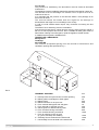
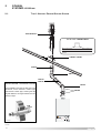
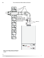
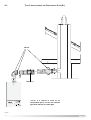
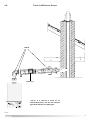
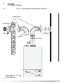
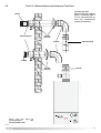
In FIG. 2.7 below, several different types of flue systems are shown.
For additional information regarding the flue accessories, please consult the Flue Pipe
Accessories manual.
Exhaust Type
Maximum Extension Diameter
of Pipes
Exhaust/Air
(mm)
(m)
C13
4
Ø 60/100
B33 outlet of fumes in
4
Ø 60/100
C13, C33, C43
42 (S1=S2)
Ø 80/80
C53, C83
76 (S1+S2)
Ø 80/80
B23
75 (S2)
Ø 80
Coaxial
Systems
chimney or exhaust flue
Twin Pipe
Systems
10
FIG. 2.7
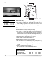
2.10.
ACCESSORY
CONNECTION
IMPORTANT!!
Before carrying out any repairs to the appliance always ensure that the
external power supply has been isolated. The boiler will remain live even when
the ON/OFF knob is in the “O”(off) position.
In order to gain access to the external control connections, it is first necessary to
lower the control panel (as shown in Section 3.2) then proceed as follows:
1. Remove the service cover on the control panel (FIG 2.8).
2. Pierce the grommett ‘M1’ (FIG. 2.9) and pass any cables for the external controls
through before connecting to the terninals.
3. Connect any external controls to their respective connections as shown in (FIG. 2.10).
FIG. 2.8
SE - EXTERNAL SENSOR
SP - UNDERFLOOR HEATING SAFETY THERMOSTAT
CR - REMOTE CONTROL
TA - ROOM THERMOSTAT
US - SECONDARY OUTLET ~230V÷50HZ (Secondary Pump, L.P.G. Valve etc.)
M1
IMPORTANT!!
Only remove the links from SP and TA if they are to be connected to external
controls.
SE
SP
CR
TA
US
FIG. 2.9
FIG. 2.10
11
2.11.
ELECTRICAL DIAGRAM
The P.C.B. is fitted with 2 fuses, on the live and the neutral.
The fuse holder contains:
- 5 x 20mm “3.15A Slow” glass fuses
A
N
M
I
I
I
K
I
K
B
H
G
L
F
C
J
D
E
O
7 8 9 10 11 121314 15 16
h
Prog
.
7 8 9 10 11 121314 15 16
m
Day
MV
OP
FI
NTC2
FS
NTC3
NTC1
VG
CI
L N
SE
SP
Q
O
P
CR
Q
S
S
R
T
12
TA
LEGEND:
A: JUMPER
When needed, the P.C.B. allows the different options to
be selected by means of a wire link.
The boiler has the following basic arrangement:
1 OPEN
2 CLOSED (jumper)
3 OPEN
4 OPEN
5 OPEN
6 CLOSED
7 CLOSED(MFFI); OPEN (SYSTEM)
8 OPEN (MFFI); OPEN (SYSTEM)
This is the factory configuration. It is recommended that this set-up not be changed,
unless under the following particular circumstances:
JUMPER 3:
if the contact is closed, the Secondary Output (flying clamp connected
to connection C7; positions 1-9) controls a LPG valve (optional).
JUMPER 4:
if the contact is closed, the continuous operation of the pump is
selected. If the contact remains open, it has no effect and there is no
change in the operation of the boiler.
JUMPER 5:
if the contact is closed, the signal transmitted by the connection of the
secondary output clasp (connected to C7; positions 1-9) relates to a
secondary pump (optional). If the contact remains open, the output
signal controls a zone valve (optional).
JUMPER 6:
not used
To configure the P.C.B. for the various boiler combinations, use JUMPERS 7 and 8 as
illustrated in the table below:
Jumper 7
Jumper 8
CONFIGURATION
contact open
contact open
RFFI + connection
to an indirect cylinder
contact closed
contact open
MFFI
contact open
contact closed
not used
contact closed
contact closed
not used
NOTE: it is essential that the operations involving setting of the jumpers be carried out
only with the device turned off.
C:
D:
E:
F:
G:
H:
I:
J:
Anti-cycling device (RA)
Maximum heating output regulation (PR)
Soft-light regulation (RLA)
ON/OFF - Operating mode selector knob
Central Heating temperature adjustment
Domestic Hot Water temperature adjustment
Relay
Transformer (PRI: 230V-50Hz; SEK: 10V-0.8VA; SEK:10V-3.5VA;
SEK:10V-3.5VA)
K:
Fuses (2 x 3.15 A SLOW)
L:
Earth
M:
Spark generator
N:
Flame detection jumper (under no circumstances should this jumper be
moved from the 1-2 position)
O:
Connection to the main P.C.B.
P:
Comfort light
Q:
Programming keys
R:
Comfort key
S:
Alpha-numeric display
T:
Set and reset key
FS:
Domestic Hot Water flow switch
PM: Pump pressure switch
NTC1: Central Heating flow temperature probe
NTC2: Central Heating return temperature probe
NTC3: Domestic Hot Water temperature probe (mod. 27 MFFI)
OP:
VG:
M:
CI:
MV:
SE:
SP:
CR:
TA:
US:
Timer
Gas valve
Diverter valve
Circulation pump with automatic air release valve
Fan
External sensor (Optional)
Under Floor Heating Connection (Optional)
Remote Control (Optional)
Room Thermostat (Optional)
Secondary outlet (Optional)
13
C1 = FAN
1:
“Hall” sensor power supply 12V (red)
2:
“Hall” sensor neutral (blue)
3:
Not used
4:
Start of coil (black)
5:
“Hall” sensor input (white)
6:
End of coil (brown)
C2 = POWER SUPPLY
1:
Earth (yellow/green)
2:
Earth (yellow/green)
3:
Not connected
4:
Neutral (blue)
5:
Not connected
6:
Live (brown)
C3 = CONNECTION TO ROOMSTAT
1:
Input - 1
2:
Input - 2
C4 = TIMER (Factory fitted for MFFI - Oprtional extra for RFFI)
1:
3 V output
2:
Timer ground
3:
Timer output
4:
Not connected
C5 = REMOTE CONTROL (Bus+/Bus-)
1:
Input/output-1
2:
Input/output-2
C6 = SENSOR CONNECTOR
1:
Domestic Hot Water flow switch (grey)
2:
Pump pressure switch (grey)
3:
Under floor heating thermostat (grey)
4:
Heating flow sensor (grey)
5:
Central Heating return sensor (grey)
6:
Domestic Hot Water sensor (grey)
7:
Not used: jumper
8:
Outdoor sensor (grey)
9:
Domestic Hot Water flow switch (grey)
10: Pump pressure switch (grey)
11: Under floor heating thermostat (grey)
12: Flow sensor (grey)
13: Central Heating sensor (grey)
14: Domestic Hot Water sensor (grey)
15: Not used: under floor heating
16: Outdoor sensor (grey)
C7 = EQUIPMENT CONNECTIONS
1:
Secondary output (optional)
2:
Gas valve (white)
3:
3-way valve neutral (white)
4:
Pump (white)
5:
Ionisation (black)
6:
Not connected
7:
Earth
8:
Pump earth (yellow/green)
9:
Secondary output (optional)
10: Gas valve (brown)
11: 3-way valve (Domestic Hot Water) (brown)
12: 3-way valve (Central Heating) (brown)
13: Pump (brown)
14: Not connected
15: Earth
16: Gas valve earth (yellow/green)
14
2.12. WATER CIRCUIT DIAGRAMS
27 MFFI
1
2
3
4
24
5
23
6
7
22
21
20
8
19
9
10
18
17
11
16
12
15
13
A
B
LEGEND:
1 - Heating flow temperature probe
2 - Air release valve
3 - Pump pressure switch
4 - Ignition/detection electrode
5 - Injector
6 - Fan
7 - Silencer
8 - Condensate discharge tube
9 - Gas valve
10 - Pressure gauge
11 - Safety valve
12 - Secondary heat exchanger
13 - Domestic hot water temperature probe
C
D
14
15
16
17
18
19
20
21
22
23
24
-
14
E
Drain valve
Domestic hot water flow switch
Motorised valve
Automatic By-pass
Circulation pump with automatic air release valve
Condensate trap inspection cap
Condensate trap
Heating return temperature probe
Expansion vessel
Main Heat exchanger
Burner
15
27 RFFI
1
2
24
3
4
23
5
6
22
21
20
7
8
9
19
10
11
12
18
E
A
17
C
D
16
13
14
B
15
Legend:
1 - Heating flow temperature probe
2 - Air release valve
3 - Ignition/detection electrode
4 - Injector
5 - Fan
6 - Silencer
7 - Condensate discharge tube
8 - Gas valve
9 - Pressure gauge
10 - Pump pressure switch
11 - Safety valve (3 bar)
12 - D.H.W. priority valve (Optional extra)
13 - Non-return valve (integral to Jig Kit)
16
14
15
16
17
18
19
20
21
22
23
24
-
Filling loop (integral to Jig Kit)
Indirect cylinder expansion vessel
Expansion relief valve
Drain valve
Automatic by-pass
Circulation pump with automatic air release valve
Condensate trap
Heating return temperature probe
Expansion vessel
Main Heat exchanger
Burner
3. COMMISSIONING
3.1.
INITIAL PREPARATION
Preliminary electrical system checks to ensure electrical safety must be carried out by a
competent person i.e. polarity, earth continuity, resistance to earth and short circuit.
FILLING THE HEATING SYSTEM:
Remove the panels of the case and lower the control panel (see section 3.2. for further
information).
Open the central heating flow and return cocks supplied with the connection kit.
Unscrew the cap on the automatic air release valve one full turn and leave open
permanently.
Close all air release valves on the central heating system.
Gradually open valve(s) at the filling point (filling-loop) connection to the central heating
system until water is heard to flow, do not open fully.
Open each air release tap starting with the lower point and close it only when clear water,
free of air, is visible.
Purge the air from the pump by unscrewing the pump plug and also manually
rotate the pump shaft in the direction indicated by the pump label to ensure the
pump is free.
Close the pump plug.
Continue filling the system until at least 1 bar registers on the pressure gauge.
Inspect the system for water soundness and remedy any leaks discovered.
FILLING OF THE D.H.W. SYSTEM:
Close all hot water draw-off taps.
Open the cold water inlet cock supplied with the connection kit.
Open slowly each draw-off tap and close it only when clear water, free of bubbles, is
visible
GAS SUPPLY:
Inspect the entire installation including the gas meter, test for soundness and purge, all
as described in BS 6891:1988.
Open the gas cock (supplied with the connection kit) to the appliance and check the gas
connector on the appliance for leaks.
When the installation and filling are completed turn on the central heating system (sect.
3.4) and run it until the temperature has reached the boiler operating temperature.
The system must then be immediately flushed through.
The flushing procedure must be in line with BS 7593:1992 Code of practice for treatment of
water in domestic hot water central heating systems.
During this operation, we highly recommend the use of a central heating flushing detergent
(Fernox Superfloc or equivalent), whose function is to dissolve any foreign matter that may
be in the system.
Substances different from these could create serious problems to the pump or other
components.
The use of an inhibitor in the system such as Fernox MB-1 or equivalent is strongly
recommended to prevent corrosion (sludge) damaging the boiler and system.
Failure to carry out this procedure may invalidate the appliance warranty.
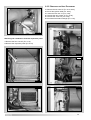
3.2.
REMOVING THE CASING
To remove the front casing panel,
follow these steps:
1. Remove the screws “A” and
lower the control panel;
2. Remove the screws “B”;
3. Lift and unhook the case panel.
3
2
1
A
A
B
B
17
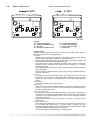
3.3.
CONTROL PANEL
27 MFFI
B
C
D
E
h
Prog
.
A
m
Day
F
G
H
KJ
I
27 RFFI
C
D
E
h
Prog
.
A
m
Day
F
G
H
KJ
18
I
A.
B.
C.
D.
E.
F.
G.
H.
I.
J.
K.
Selector Knob for ON/OFF-Summer-Winter
Domestic Hot Water Temperature Adjustment Knob
Central Heating Temperature Adjustment Knob
Time Clock (Optional for ecoSYSTEM)
Heating System Pressure Gauge
Programming “+” key
Programming “-” key
Reset Button
Multifunction Display
“COMFORT” Function L.E.D./Heating Only (ecoSYSTEM)
“COMFORT” Function Push-Button/Heating Only (ecoSYSTEM)/Test Mode (*)
(*)
See Section 3.7.5 Flue Test Mode
3.4.
INITIAL START-UP
1. Make sure that:
- the cap of the automatic air release valve is loosened;
- the system pressure is at least 1 bar on the pressure gauge;
- the gas cock is closed;
- the electrical connection has been carried out in the correct manner.
To allow the air to escape from the system, proceed as follows:
- turn on the On/off knob “A” to the “winter” position. The boiler pump will start up and
three consecutive attempts will be made to ignite the burner. After the third attempt, the
electronic system will shutdown the boiler, because the supply of gas has been cut off.
The message “A01” will appear on the display;
- let the pump operate until all the air has escaped from the system;
- repeat the procedure for bleeding the radiators of air;
- draw hot water for a short while;
- check the system pressure and, if it has gone down, fill it with water until it returns to 1
bar.
2. Check the flue system for products of combustion.
3. Fill the boiler condensate trap with water.
N.B. In the event of a prolonged period of system shutdown, the condensate trap
should be filled before any renewed use. A shortage of water in the trap is
dangerous because it could possibly lead to a leakage of fumes into the air.
4. Turn on the gas cock and check the seals on the connections, including the one for the
burner, making sure that the meter does not signal the passage of gas. Check the
connections with a soap solution and eliminate any leaks.
FIG. 3.1
5. Press the reset button “H” for the lighting system; the spark will light the main burner. If
the burner does not light the first time, repeat the procedure.
The boiler is configured in the factory for the gas type in question. To check the
air/gas ratio, please refer to section 3.6.4.
19
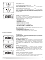
3.5.
DISPLAY: MESSAGES
SHOWN DURING
NORMAL OPERATION
During operation of the boiler, while it is carrying out its normal operations, the left-hand
display shows a series of characters that refer to the operations indicated below:
- Diagnostics phase (precedes the other operations)
0
No request for heat
C
Heating, burner off
C.
Heating, burner on
c
Pump overrun for heating
d
Domestic hot water, burner off
d.
Domestic hot water, burner on
h
Pump overrun for domestic hot water
b
Storage cylinder, burner off (SYSTEM version)
b.
Storage cylinder, burner on (SYSTEM version)
FIG. 3.2
NOTE: the flashing dot on the left-hand display always indicates “burner off”; while the still
dot indicates “burner on”.
LEFT
RIGHT
The right-hand display (two-digit) shows:
- in CENTRAL HEATING mode: temperature of the Central Heating system flow;
- in DOMESTIC HOT WATER mode: temperature of the Domestic Hot Water (MFFI only).
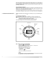
3.6.
OPERATING PARAMETERS
3.6.1
REGULATION MENU TABLE
The boiler has been designed to allow easy intervention with regard to the operating
parameters.
Summary of the functions accessed when the RESET button is pushed for 5 seconds.
left-hand display
right-hand display
Function
factory setting
A
da0 1 a 2 4
Pump overrun
set to 0 3
r
00
01
Selects low temperature
systems or std systems
set to 0 1
d
da1 2 a 2 8
Correction of heat curve
translation
set to2 0
n
da0 0 a 1 2
night-time lowering
of the temperature
set to 0 0
F
da0 1 a 0 9
curve incline
set to 0 9
S
da8 1 a 8 9
do not use
t
t/s
__
--
00
01
test mode
see next paragraph
do not use
set to 0 0
Important!!
Parameters d, n and F are only enabled when the outdoor sensor is
connected.
To return to the normal display, press the “H” reset key repeatedly until all the sequence of
“readout” functions have scrolled through the display and until one of the “display of normal
operations” has appeared (the message that appears will depend on the current operating
mode of the boiler).
20
PUMP OVERRUN
G-
F+
FIG. 3.3
H
G-
F+
FIG. 3.4
The pump overrun may be varied (after the burner has been turned off). To access this
function, it is necessary to press the reset button for over 5 seconds and then press it
A” appears on the left-hand display.
repeatedly until the character “A
The following modes are available:
01
1 minute of pump overrun
03
3 minutes of pump overrun
06
6 minutes of pump overrun
09
9 minutes of pump overrun
12
12 minutes of pump overrun
15
15 minutes of pump overrun
CO
24 hours of pump overrun
It is also possible to set a continuous pump operation by closing the contact of jumper 4
(see section 2.11.).
SETTING THE TEMPERATURE FIELD
Using the programming key, the setting may be changed. It is possible to choose two
fields of regulation of the flow temperature.
00” signifies that the flow temperature (which may be set by means of the knob on
“0
the front control panel) may be regulated from 30 to 75°C.
01” signifies that the flow temperature (which also may be set by means of the knob
“0
on the front control panel) may be regulated from 42 to 82 °C.
H
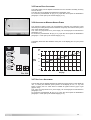
SETTING THE CURVE INCLINE
G-
F+
FIG. 3.5
H
(Only enabled when an outdoor sensor is installed)
In the case of the use of an outdoor sensor, the microprocessor-controlled P.C.B.
calculates the most suitable flow temperature, taking into account the external
temperature and the type of system. The microprocessor is capable of doing this
because it is possible to establish a link between the external temperature and the flow
temperature of the Central Heating system water. This link translates into a "thermal
curve".
The type of curve should be chosen in correspondence with the planned temperature of
the system and the nature of the heat loss present in the building.
9
100
8
7
6
WARNING
(*) - If curve 1, 2 or 3 is set,
a system safety
thermostat must be
connected to the main
terminal board (see
paragraph 2.10)
Flow temperature (°C)
5
4
60
3
2
1
20
+20
External temperature (°C)
-20
Using programming keys F and G, the curve setting may be changed. The possibility
of setting curves varies according to parameter r:
r = 00 (low temperature range) from curve 1 to 6
r = 01 (high temperature range) from curve 5 to 9.
CURVE 1:
CURVE 2-3:
CURVE 4-5:
CURVE 6-7:
CURVE 8-9:
under floor heating (radiant panels at ultra-low
temperature). Planned temperature 30/20°C.
under floor heating (radiant panels, low temperature radiant plate systems).
Planned temperature 40/30°C.
conventional low temperature boilers (cast iron and aluminum radiators,
radiant plate systems). Planned temperature 60/45°C.
conventional low temperature boilers (cast iron and aluminum radiators,
radiant plate systems). Planned temperature 75/60°C.
boilers with higher temperatures (radiators, convectors, fan coils). Planned
temperature 90/75°C.
Adapting the heat curve “d” set”
G-
F+
FIG. 3.6
H
(Only enabled when an outdoor sensor is installed)
To adapt the heat curve to the system requirements, set parameter “d” in order
to shift the curve in parallel, so that the flow temperature calculated is changed,
along with the ambient temperature.
When “d” appears on the left-hand display, use the heating control knob to shift
the curve in parallel as illustrated in the figure below. The shift value can be
read on the right-hand display, from 12 to 28.
Flow temperature (˚C)
100
6
nto
me
a
urv
u
-a
ac
o
lel
ral
a
op
ll
de
nt
me
ne
ta
os
60
zio
nu
sp
rva
to
en
cu
od
lel
l
ara
a
ell
i
dim
p
m
sta
o
sp
20
+20
External temperature (˚C)
Night-time lowering of the temperature
G-
F+
FIG. 3.7
H
G-
F+
H
FIG. 3.8
To select operation at minimum power, press the programming key - “G”, two dashes
will appear at the bottom of the right-hand display (see Fig. 3.10). This function is
disabled when you press reset key “H” to quit the adjustments menu.
H
FIG. 3.9
t
The P.C.B. allows the boiler to be forced to the maximum or minimum power. Enable
the test function and OO will appear on the right-hand display (see Fig. 3.8).
To select operation at maximum power, press the programming key + “F”, two dashes
will appear at the top of the right-hand display (see Fig. 3.9).
This function is disabled when you press reset key “H” to quit the adjustments menu.
G-
F+
G-
F+
22
n
(Only enabled when an outdoor sensor is installed and the timer is connected)
If the remote control is installed (see paragraph 2.10), two different temperatures can
be set: one for the day-time and one for night-time. It is therefore possible to lower the
temperature that the P.C.B. calculates in relation to the values provided by the outdoor
sensor by a quantity decided by the user for night-time operation. To do so, select the
night-time function “n” and using programming keys F and G, select a value between
0 and 12, depending how much the night-time temperature is to be lowered.
Test Function
FIG. 3.10
-20
H
Note: The boiler can be forced to the maximum and minimum power even without
enabling the test function but via the adjustments menu:
a - by pressing the Comfort key “K”, the boiler is automatically forced to maximum
power (flue sweep function), two dashes appear at the top of the right-hand
display (see Fig. 3.9). This function is disabled by pressing the reset key “H”.
b - by pressing keys “K” and “H” simultaneously, the boiler is forced to operate at
minimum power, two dashes appear at the bottom of the right-hand display (Fig.
3.10). This function is disabled by pressing the reset key “H”.
3.6.2
SETTINGS DISPLAY
The boiler is designed to monitor some operating variables and settings by means of the
display on the front control panel. Keeping the reset key pressed for over 10 seconds
allows access to the “readout” function of the main system variables. By pressing the
button repeatedly after that, it is possible to read the following information in sequence:
Indication on the
left-hand display
U/1
U/2
U/5
U/F
U/t
P/A
P/-
Value read on right-hand display
Flow temperature of the Central Heating circuit (°C)
Return temperature of the Central Heating circuit (°C)
Domestic Hot Water output temperature (°C)
Ionisation current (expressed in bT)
Main circuit flow switch
Heating ignition delay (see section 3.6.4. - expressed in min.x1)
Maximum thermal power for heating (expressed in a percentage of
the difference between the maximum power allowed by the boiler
and the minimum)
P/L
Soft light power (expressed in a percentage of the difference
between the maximum power allowed by the boiler and the
b
l
minimum)
Last safety shut-off (see section 3.7.)
Last shutdown (see section 3.7.)
To return to the normal display, press the “H” reset key repeatedly until all the sequence
of “readout” functions have scrolled through the display and until one of the “display of
normal operations” has appeared (the message that appears will depend on the current
operating mode of the boiler).
U” and “1
1” blink alternately on the display
* NOTE 1: U/1 means that “U
00” on the display
NOTE 2: the value 100% appears as “0
3.6.3 COMFORT KEY:
27 MFFI
The boiler allows the convenience level to be increased in the output of domestic hot water
by means of the “COMFORT” function. This function keeps the secondary exchanger warm
during the periods in which the boiler is inactive, thereby allowing the initial water drawn to
be at a higher temperature. The function may be activated by pressing the “K” key on the
control panel (see section 3.3.). When the function is active, a green light comes on, again
located on the control panel.
NOTE: During the overrun period of the pump, the “COMFORT” function, if selected, is
temporarily deactivated. The L.E.D. light remains on to indicate that the boiler will return to
the “COMFORT” mode once the pump overrun is terminated.
23
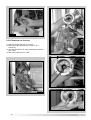
3.6.4 GAS REGULATION CHECK
4
3
2
1
2
3
1
4
FIG. 3.11
FIG. 3.12
Supply pressure
G20 methane
G30 butane
G31 propane
17-25 mbar
25-35 mbar
25-45 mbar
Supply pressure check
1. Loosen screw “1” (Fig. 3.12) and insert the pressure gauge connection pipe into
the pipe tap.
2. Turn the boiler on at maximum power, enabling the “flue sweep” function (press the
Comfort key “K” for 5 seconds). The supply pressure should correspond to that
foreseen for the type of gas the boiler is designed for (See table 4C).
3. When the check is over, tighten screw “1” and make sure it is securely in place.
4. Disable the flue sweep function by pressing the reset key “H”.
AIR/GAS RATIO CHECK
Air/gas ratio at minimum power
To check the air/gas ratio at minimum power, proceed as follows:
1. Connect the combustion analyser to the analysis point (Fig. 3.11) after removing
the cover plate.
2. Turn the boiler on at minimum power via the test function (see paragraph 3.6.1) or
by pressing keys “K” and “H” simultaneously on the control panel. Ensure the CO2
value on the analyser corresponds with the value indicated in table 4D. If this is not
the case, adjust screw “2” with a screwdriver, after removing the cap, until you
obtain the correct CO2 reading. Allow the reading to become stable for at least 4
minutes.
3. When the check is over, replace the cap on screw “2” (Fig. 3.11).
4. Disable operation at minimum power by pressing key “H”.
Air/gas ratio at maximum power
To check the air/gas ratio at maximum power, proceed as follows:
1. With the combustion analyser already connected to the analysis point, set the
boiler to maximum power via the test function (see paragraph 3.6.1) or enabling
the “flue sweep function” by pressing the Comfort key “K” for 5 seconds.
Ensure the CO2 value on the analyser corresponds with the value indicated in
table 4D. If this is not the case, adjust screw “4” with a screwdriver (Fig. 3.12), until
you obtain the correct CO2 reading. Allow the reading to become stable for at least
4 minutes.
2. Disable the “flue sweep function” by pressing key “H”.
The “flue sweep function” is automatically disabled after 5 minutes.
3. Repeat the air/gas ratio at minimum power check (see above).
4. Disconnect the analyser, remount the cover plate and check it is securely in place.
AIR/GAS RATIO SETTING
Calibration values check
CO2 at minimum power
after 4 minutes of operation
24
methane G20
butane G30
propane G31
% vol
% vol
% vol
10 ±0.2
11.5 ±0.2
11.5 ±0.2
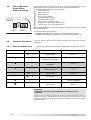
3.6.5 IGNITION DELAY ADJUSTMENT
The ignition delay can be adjusted to between 0 and 15 minutes. The delay is factory
set to 2 minutes.
The value set can be displayed as illustrated in paragraph 3.6.2.
To access the potentiometer “C” (Fig. 3.14), open the control panel as illustrated in
paragraph 3.2 and open up the service flap (Fig. 3.13).
3.6.6 ADJUSTING THE MAXIMUM HEATING POWER
FIG. 3.13
The maximum heating power can be adjusted to between the maximum power
allowed by the boiler (24 kW) and the minimum one (8 kW). The value is factory set to
70% of the maximum power.
The value set (expressed as a percentage) can be displayed as illustrated in
paragraph 3.6.2.
To access the potentiometer “D” (Fig. 3.14), open the control panel as illustrated in
paragraph 3.1 and open up the service flap (Fig. 3.13).
The display shows the value between 100% ("00" on the display) and 1% ("01") of this
interval.
kW
25
C
20
D
Heat
input
E
15
10
5
0
0
10
20
30
FIG. 3.14
40
50
60
Display
70
80
90
100 %
3.6.7 SOFT LIGHT ADJUSTMENT
The soft light can be adjusted between the maximum power (shown on the display as
"00", i.e. 100%) and minimum power (shown on the display as "01", i.e. 1%). The
boiler is factory set to a value which is suitable for ignition with any type of gas
(approx. 33%).
The value set (expressed as a percentage) can be displayed as illustrated in
paragraph 3.6.2.
To access the potentiometer “E” (Fig. 3.14), open the control panel as illustrated in
paragraph 3.1 and open up the service flap (Fig. 3.13).
25
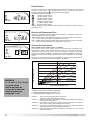
3.7 Gas Changeover
The boiler operation can be changed over from methane gas (G20) to Liquid Gas
(G30-G31) or vice versa, an operation that must be performed by an Authorised
Service Centre.
The operations to carry out are the following:
1. Replacement of the nozzle (see table);
2. Replacement of the gas label;
3. Air/gas ratio adjustment to be made in accordance with paragraph 3.6.4
GAS LIQUIDO
GAS METANO
Diameter of 6 nozzle holes (mm)
Display of recommended soft light power
1
G30
G31
2.8
2.0
2.0
33%
33%
33%
Place the boiler in operation in accordance with the End User Manual.
Check the seal on the gas and water sides.
Check that the ignition operates correctly and visually check the burner flame.
Check that the domestic hot water is being correctly produced by drawing hot water.
Check the rate of flow and/or temperature of the water, depending on the case.
Check that the condensate drips without difficulty into the discharge.
2
3
4
26
G20
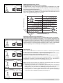
3.8.
BOILER SAFETY SYSTEMS
The boiler is protected from malfunctioning by means of internal checks by the P.C.B.,
which brings the boiler to a stop if necessary.
In the event of the boiler being shut off in this manner, a code appears on the display
which refers to the type of shut-off and the reason behind it.
There are two types of shut-off:
-
SAFETY SHUTDOWN: for this group of errors (characterised on the display by
E”) the situation is automatically removed as soon as the cause behind
the letter “E
it is resolved.
As soon as the origin of the shutdown disappears, the boiler starts up again and
returns to its normal operation.
-
A”), is not removed
SHUTDOWN: (characterised on the display by the letter “A
unless a manual intervention is made.
The boiler may return to operation only if reset by pressing the button “H” located
at the centre of the display.
There follows a list of the shutdown modes and the respective codes shown on the
display.
A” type): if such a situation occurs, it is necessary to reset the boiler using
Shutdown (“A
the appropriate key. If this shutdown occurs again, your local Service Agent should be
contacted.
DISPLAY
CAUSE
A01
Too many attempts to ignite on starting up
A02
After three attempts at ignition, no increase in DT was detected
A03
The heating flow temperature exceeds 100°C during operation
A07
Too many failures to flame in one period during operation
A19
The flame was detected after the gas valve had closed
A20
The flame was detected before the gas valve opened
A21
The flow switch does not close
A22
The flow switch does not open
A33
Problem with the fan
A99
Problem with the electronic monitoring
NOTE:
When there is no ignition, check that the gas cock is open.
Safety shutdown: In the event that a safety shutdown occurs, it is necessary to contact an
Authorised Service Centre.
DISPLAY
CAUSE
E01
Insufficient water pressure
E56
Heating flow temperature probe in open circuit
E66
Heating flow temperature probe short-circuited
E04
Domestic hot water temperature probe in open circuit
E05
Domestic hot water temperature probe in short circuit
E08
Under floor heating temperature probe in open circuit
E20
Flame detected with gas valve closed
E21
Error in the electrical connection (live and neutral crossed)
E22
Problem with the 50Hz power supply
E23
Flame detection electrode short-circuited
E64
Heating return temperature probe in open circuit
E74
Heating return temperature probe in short circuit
E99
Problem within the electronic system
DAILY TEST.
In order to prevent the shutdown of the components, the boiler carries out a selfdiagnosing test every 24 hours: the pump turns on for 3 seconds and the diverter valve
moves.
ANTI-FROST DEVICE.
The boiler is fitted with an anti-frost device consisting of three separate functions:
- Monitoring of the system flow temperature: if this temperature goes below 5°C, the
27
pump turns on (heating system circulation). If the temperature goes below 2°C, the
boiler turns on at the minimum power and remains on until the return temperature
is over 10°C.
- Outdoor sensor installed: the pump turns on if the external temperature goes below
-3°C, it turns off when the external temperatures raises above -1°C.
- Continuous operation of the pump: select by means of jumper 4 (see paragraph
2.11).
NOTE: In all cases, the circulation takes place in the heating system.
The anti-frost device activates only when (with the boiler operating correctly):
- the system pressure is correct;
- the boiler is electrically powered;
- there is a supply of gas.
ANTI-SCALE DEVICE.
When producing domestic hot water, the burner shuts off whenever the output
temperature of the hot water exceeds 62°C or the flow temperature of the primary
circuit exceeds 72°C. It will not turn on if the temperature of the primary circuit is
greater than 72°C.
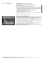
COMBUSTION ANALYSIS
3.9.
The boiler is designed to allow for easy analysis of the products of combustion.
Using the special traps, it is possible to detect the temperature of the burnt gas, the
combustion air, the concentrations of O2, CO2, etc.
To access these traps, unscrew the front screw and remove the metal plate and
relevant seal.
The best test conditions, with the maximum heating power, are achieved when the
FLUE SWEEP FUNCTION is enabled (press the RESET KEY “H” for 5 seconds).
The boiler will return to normal operating conditions automatically after 5 minutes,
or if you press the reset key “H”. When you have finished, reposition the metal
plate correctly and make sure the seal fits perfectly.
FU008A
3.10
DRAINING
The draining of the heating system must be carried out as follows:
Turn off the boiler and the bipolar switch;
Loosen the automatic air release valve;
Open the system's discharge valve and gather the water that comes out in a container;
Empty out from the lowest points of the system (where provided).
If the system is to be left active in areas where the room temperature may go below 0°C
during winter, it is recommended that anti-freeze liquid be added to the water in the heating
system in order to avoid the need for repeated draining.
Draining the domestic hot water system
Every time that there is a danger of freezing, the domestic hot water system must be
drained as follows:
close the water mains stop-cock;
open all the hot and cold water outlets;
empty out from the lowest points (where provided).
28
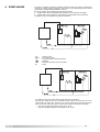
4. ZONE VALVES
The boiler is capable of managing a heating system that uses zone valves. The electrical
connection of these valves is carried out by means of the appropriate terminal board
(indicated in the “ELECTRICAL CONNECTION” section).
By way of example, two possible types of systems would be:
1. System with 2 valves with independent regulation of the zones (day and night).
2. System with 1 valve (regulation of the night zone subordinated to that of the day).
A possible set-up for the first type of system is as follows:
CR
VZ1,2
TA
F,N
RL
= remote control
= zone valve 1 and 2
= room thermostat or timer-thermostat
= radiators
= electrical connection (live and neutral)
= relay
A possible set-up for the system with a single zone valve is as follows:
This set-up is simpler and more economical because it does not involve the use of the
special relay. The night zone, however, may only be heated during the time periods in
which the remote control timer gives consent to the heating of the day zone. Example:
•
day zone programming (remote control): 8:00 - 22:00
•
night zone programming (timer-thermostat): 20:00 - 22:00
29
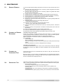
5. MAINTENANCE
5.1.
GENERAL REMARKS
5.2.
CLEANING THE PRIMARY
EXCHANGER
It is recommended that the following inspections be carried out on the boiler at least once a
year:
1. Check the seals in the water group and, if necessary, replace the gaskets and restore
the seal to perfect working order.
2. Check the seals in the gas group and, if necessary, replace the gaskets and restore
the seal to perfect working order.
3. Visually check the overall state of the boiler.
4. Visually check the combustion and, if necessary, disassemble and clean the burner.
5. Following inspection 3, disassemble and clean the combustion chamber, if necessary.
6. Following inspection 4, disassemble and clean the injector, if necessary.
7. Clean the primary heat exchanger (see section 6.2)
8. Regulate the correct rate of flow of the gas: rate of flow on ignition, partially loaded and
at maximum load.
9. Check the correct functioning of the heating safety devices:
- temperature limit safety device.
10. Check the correct functioning of the gas group safety devices:
- absence of gas or flame safety device (Ionisation).
11. Check that the electrical connections are correct (in conformity with the instructions
manual).
12. Check the efficiency of the production of domestic hot water (test the rate of flow and
temperature).
13. Carry out a general inspection of the functioning of the boiler.
14. Check the characteristics for expulsion of the products of combustion.
15. Remove the oxide from the detection electrode by means of an emery cloth.
CLEANING THE EXHAUST SIDE
Remove the combustion chamber inspection hatch (see section 1.3). Check that the
exhaust passages between the blades of the block are free; if there are deposits present,
wash the blades with compressed air, water or a vinegar-based detergent.
NOTE: it is possible to use a brush in order to mechanically remove the residues.
Use of detergents:
soak the blades well
allow the detergent to act for about 20 minutes
rinse with a strong jet of water to remove the deposits (the control panel must be kept
closed)
make sure that there are no traces of detergents in the exchanger.
CLEANING THE WATER SIDE
Use detergents that dissolve CaCO3. Leave to act for a short time (in order not to damage
the aluminum) and then rinse. Make sure that the detergent does not remain inside the
exchanger.
5.3.
CLEANING THE
CONDENSATE TRAP
Unscrew the lower part of the condensate trap and clean it. Lastly, fill it with water and
replace the stopper.
NB: if the boiler is not to be used for a prolonged period, the condensate trap should be
filled before igniting it again. A shortage of water in the trap is dangerous because there is
the risk of exhaust fumes escaping into the air.
5.4.
OPERATIONAL TEST
30
After having carried out the maintenance operations, fill the heating circuit to a pressure of
approx. 1.5 bar and release the air from the system. Also fill the domestic hot water system.
Place the boiler in operation.
If necessary, release the air again from the heating system.
Check the settings and the correct functioning of all the control, regulation and
monitoring parts.
Check the seal and the correct functioning of the system for expelling fumes/drawing
of combustion air.
Check that the boiler ignites properly and carry out a visual check on the burner flame.
6.
SERVICING
INSTRUCTIONS
To ensure efficient safe operation, it is recommended that the boiler is
serviced annually by a competent person.
Before starting any servicing work, ensure both the gas and electrical
supplies to the boiler are isolated and the boiler is cool.
Before and after servicing, a combustion analysis should be made via the flue
sampling point (please refer to the Installation Manual for further details).
After servicing, preliminary electrical system checks must be carried out to
ensure electrical safety (i.e. polarity, earth continuity, resistance to earth and
short circuit).
6.1.
REPLACEMENT
OF PARTS
The life of individual components vary and they will need servicing or
replacing as and when faults develop.
The fault finding sequence chart in chapter 2 will help to locate which
component is the cause of any malfunction, and instructions for removal,
inspection and replacement of the individual parts are given in the following
pages.
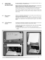
6.2.
TO GAIN GENERAL
ACCESS
All testing and maintenance operations on the boiler require the control panel
to be lowered. This will also require the removal of the casing.
To lower the control panel and dismantle the front part of the casing,
proceed as follows:
1. Unscrew screws “A” (FIG. 6.1) and rotate the control panel forward;
2. Unscrew the screws “B” (FIG. 6.2 + FIG. 6.3) and unhook the front panel by
lifting it.
FIG. 6.1
A
A
FIG. 6.2
B
B
FIG. 6.3
31
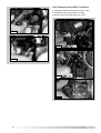
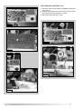
6.2.1. REMOVING THE SIDE PANELS
6.3.
1. Remove the screws “C” (FIG. 6.4);
2. Pull each panel away from the boiler, then lift the
panel up and away from the boiler.
ACCESS TO THE
COMBUSTION CHAMBER
Removing the sealed chamber front cover
1. Remove the screws “D” (FIG. 6.5);
2. Pull the cover away from the boiler (FIG. 6.6).
C
D
D
FIG. 6.5
C
FIG. 6.4
FIG. 6.6
32
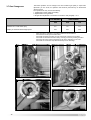
6.3.1. REMOVING THE FAN
FIG. 6.9
1. Disconnect the electrical connector “E” (FIG. 6.7);
2. Disconnect the compensation tube “F” (FIG. 6.8);
2. Unscrew the three screws “G” (FIG. 6.9);
3. Pull the fan away from the mixing tube (FIG. 6.10).
4. Unscrew the screws “H” (FIG. 6.11) and remove the
silencer.
G
G
E
FIG. 6.7
FIG. 6.10
H
H
F
H
FIG. 6.8
FIG. 6.11
33
6.3.2. REMOVING THE BURNER
With the fan removed (see previous section);
1. Loosen nut “I” (FIG. 6.12);
2. Remove nuts “J” (FIG. 6.13);
3. Remove mixing tube (FIG. 6.14);
4. Slide the burner from its housing (FIG. 6.15).
FIG. 6.15
I
6.3.3. REMOVING THE ELECTRODES
FIG. 6.12
1. Pull off the ignition cable “K” (FIG. 6.16);
2. Remove the two allen screws “L” (FIG. 6.17);
3. Extract the electodes (FIG. 6.18).
K
J
FIG. 6.16
FIG. 6.13
L
L
FIG. 6.17
FIG. 6.14
34
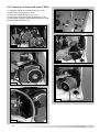
6.3.5. REMOVING THE HEAT EXCHANGER
1. Remove the two nuts “N” (FIG. 6.21+6.22);
2. Pull off the ignition cable (FIG. 6.23);
3. Loosen the two nuts “O” (FIG. 6.24);
4. Unscrew the two screws “P” (FIG. 6.25);
5. Unscrew the screw “Q” (FIG. 6.26);
6. Pull foward rhe heat exchanger (FIG. 6.27);
FIG. 6.18
N
Removing the combustion chamber inspection panel
1. Remove the four nuts “M” (FIG. 6.19);
2. Remove the inspection panel (FIG. 6.20).
FIG. 6.21
M
M
FIG. 6.22
N
M
M
FIG. 6.19
FIG. 6.20
FIG. 6.23
35
O
O
FIG. 6.24
FIG. 6.25
FIG. 6.27
FIG. 6.28
P
P
P
FIG. 6.26
Q
36
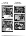
6.3.6. REMOVING THE CONDENSATE COLLECTOR
6.3.7. REMOVING THE CONDENSATE TRAP
1. Open the clamp and remove the condensate trap
connection pipe “R” (FIG. 6.29);
2. Remove the nuts “S” (FIG. 6.30);
3. Remove the condensate collector (FIG. 6.31).
1. Open the clamp and remove the condensate trap
connection pipe (FIG. 6.29+6.32);
2. Unscrew and remove the trap from the boiler (FIG.
6.33).
3. Remove the condensate trap (FIG. 6.34+6.35).
R
FIG. 6.29
FIG. 6.32
S
FIG. 6.30
Fig. 6.33
FIG. 6.31
Fig. 6.34
37
Fig. 6.35
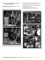
6.3.8. REMOVING THE INJECTOR
1. Remove mixing pipe (FIG. 6.12+6.13);
2. Remove the fan, unscrew the screws “T” (FIG.
6.36+6.37);
3. Unscrew the injector “U” using a suitable screwdriver
(FIG. 6.38);
4. Remove the injector (FIG. 6.39).
Fig. 6.37
U
T
T
T
Fig. 6.38
Fig. 6.36
Fig. 6.39
38
6.4
ACCESS TO THE GAS VALVE
6.4.1. REMOVING THE GAS VALVE
1. Disconnect the electrical connection “V” from the gas
valve (FIG. 6.40);
2. Release the top nut “W” (FIG. 6.41);
3. Remove the screws “X” from the bottom of the gas
valve pipe (FIG. 6.42);
4. Remove the gas valve (FIG. 6.43).
X
X
FIG. 6.42
V
FIG. 6.40
W
FIG. 6.43
FIG. 6.41
39
6.5
ACCESS TO THE WATER CIRCUIT
Important! Before any component is removed, the boiler
must be drained of all water.
6.5.1. REMOVING THE D.H.W. (SECONDARY)
EXCHANGER
6.5.2. REMOVING THE SAFETY VALVE
(ECOCOMBI 27 MFFI)
1. Remove the U-clip “Z” (Fig. 6.47);
2. Unscrew and remove the valve (Fig. 6.48).
1. Remove the screws “Y” (FIG. 6.44);
3. Push the exchanger towards the rear of the boiler, lift
upwards and remove from the front of the boiler (FIG.
6.45 - 6.46);
4. Before replacing the exchanger ensure that the Orings are in good condition and replace if necessary.
Z
Y
FIG. 6.44
Y
FIG. 6.47
FIG. 6.45
FIG. 6.48
FIG. 6.46
40
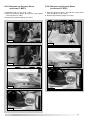
6.5.2. REMOVING THE SAFETY VALVE
(ECOSYSTEM 27 RFFI)
6.5.2. REMOVING THE AUTOMATIC AIR VENT
(ECOCOMBI 27 MFFI)
1. Loosen union “A1” (Fig. 6.49);
2. Unscrew and remove the valve (Fig. 6.50).
1. Remove the U-clip “A2” (FIG. 6.51);
2. Unscrew valve (FIG. 6.52);
3. Remove (FIG. 6.53).
A2
A1
FIG. 6.51
FIG. 6.49
FIG. 6.52
FIG. 6.53
FIG. 6.50
41
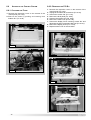
6.5.3. REMOVING THE AUTOMATIC AIR VENT
(ECOSYSTEM 27 RFFI)
6.5.4. REMOVING THE PUMP PRESSURE SWITCH
(ECOCOMBI 27 MFFI)
1. Unscrew valve “A3” (FIG. 6.54);
2. Remove (FIG. 6.55).
1. Remove the electrical connections “A4” (FIG. 6.56);
2. Unscrew and remove (FIG. 6.57).
A3
A4
FIG. 6.54
FIG. 6.56
FIG. 6.55
FIG. 6.57
42
6.5.4. REMOVING THE PUMP PRESSURE SWITCH
(ECOSYSTEM 27 RFFI)
1. Remove the electrical connections “A5” (FIG. 6.56);
2. Unscrew and remove (FIG. 6.57).
6.5.5. REMOVING THE DIVERTER VALVE ACTUATOR
1. Unplug the electrical connector “A6” (FIG. 6.60);
2. Release the retaining clip “A7” and remove the diverter
valve actuator (FIG. 6.61).
3. Unscrew the two screws “A8” (FIG. 6.62);
4. Remove the “actuator” “A9” (FIG. 6.63 - 6.64).
A5
A6
FIG. 6.60
FIG. 6.58
A7
FIG. 6.61
A8
FIG. 6.59
FIG. 6.62
43
6.5.6. REMOVING THE D.H.W. FLOW SWITCH
1. Unplug the electrical connector “B1” (FIG. 6.65);
2. Unscrew the four screws “B2” (FIG. 6.66);
3. Remove the D.H.W. flow switch (FIG. 6.67).
A9
FIG. 6.63
B1
A9
FIG. 6.65
FIG. 6.64
B2
FIG. 6.66
FIG. 6.67
44
6.5.7. REMOVING THE PUMP (ECOCOMBI 27 MFFI)
1. Unplug the electrical connection “B3” (FIG. 6.68);
2. Unscew the four scews “B4” (FIG. 6.69);
3. Remove the pump (FIG. 6.70 - 6.71).
B3
FIG. 6.70
FIG. 6.68
B4
FIG. 6.71
FIG. 6.69
45
6.5.7. REMOVING THE PUMP (ECOSYSTEM 27 RFFI)
1.
2.
3.
4.
5.
6.
Unplug the electrical connection “B5” (FIG. 6.72);
Remove the U-clip “B6” (FIG. 6.73);
Remove the slide plate “B7” (FIG. 6.74);
Unscew the screw “B8” under the boiler (FIG. 6.75);
Remove the U-clip “B9” of the pressure gauge (FIG. 6.76);
Remove the pump (FIG. 6.77).
B5
B8
FIG. 6.75
FIG. 6.72
B9
B6
FIG. 6.76
FIG. 6.73
FIG. 6.77
B7
FIG. 6.74
46
6.5.8. REMOVING THE PRESSURE GAUGE
(ECOCOMBI 27 MFFI)
6.5.8. REMOVING THE PRESSURE GAUGE
(ECOSYSTEM 27 RFFI)
1. Release U-clip “C1” (FIG. 6.78 - 6.79);
2. Ease the pressure gauge through the control panel
from the rear (FIG. 6.80);
3. Remove the pressure gauge. (FIG 6.81).
1. Ease the pressure gauge through the control panel
from the rear (FIG. 6.82 - 6.83);
2. Remove the pressure gauge. (FIG 6.84).
C1
FIG. 6.78
FIG. 6.82
FIG. 6.79
FIG. 6.83
FIG. 6.80
FIG. 6.84
FIG. 6.81
47
6.5.9. REMOVING THE EXPANSION VESSEL
1. Loosen nut “C2” (FIG. 6.85);
2. Loosen nut “C3” (FIG. 6.86);
3. Remove the expansion vessel (FIG. 6.87).
6.5.10 R EMOVING THE D.H.W. T EMPERATURE
PROBE (N.T.C.) (MFFI ONLY)
1. Remove the electrical connector “C4” by pulling off
(Fig. 6.88);
2. Unscrew and remove the D.H.W. temperature probe
“C5” (FIG. 6.89).
C4
C2
FIG. 6.85
FIG. 6.88
C3
C5
FIG. 6.89
FIG. 6.86
FIG. 6.87
48
6.5.11. Removing the C.H. Flow Temperature
Probe (N.T.C.)
6.5.12. REMOVING THE C.H. RETURN TEMPERATURE
PROBE (N.T.C.)
1. Remove the C.H. flow temperature probe “C6” by
pulling off (Fig. 6.90);
2. Remove the electrical connection from the C.H. flow
temperature probe “C7” (FIG. 6.91).
1. Remove the C.H. return temperature probe “C8” by
pulling off (Fig. 6.92);
2. Remove the electrical connection from the C.H. return
temperature probe “C9” (FIG. 6.93).
C6
C8
FIG. 6.90
FIG. 6.92
C9
C7
FIG. 6.91
FIG. 6.93
49
6.6
ACCESS TO THE CONTROL SYSTEM
6.6.1. CHECKING THE FUSES
1. Remove the inspection cover on the reverse of the
control panel (FIG. 6.94);
2. Remove the fuses by pushing and rotating fuse
holders “D1” (FIG. 6.95).
6.6.2. REMOVING THE P.C.B.S
1. Remove the inspection cover on the reverse of the
control panel (FIG. 6.94);
2. Unplug all the electrical connections (FIG. 6.96);
3. Unscew the screws “D2” (FIG. 6.97);
4. Remove the facia panel (FIG. 6.98);
5. Unscrew the screws “D3” (Fig. 6.99);
6. Remove the main P.C.B. (FIG. 6.100);
7. Unscew the display P.C.B. mounting screws “D4” and
disconnect the P.C.B. connection cable “D5” (FIG. 6.101);
8. Remove the display P.C.B. (FIG. 6.102);
9. Replace either P.C.B. in reverse order.
FIG. 6.94
FIG. 6.96
D1
FIG. 6.95
D2
FIG. 6.97
FIG. 6.98
50
D2
6.6.3. REMOVING THE TIME CLOCK
D3
D3
1. Open the control panel (see the paragraph “Removing
the P.C.B.s”);
2. Unplug the electrical connection from the time clock
and unscews the four scews (FIG. 6.103);
3. remove the time clock (FIG. 6.104).
FIG. 6.99
FIG. 6.103
FIG. 6.100
FIG. 6.101
D5
D4
FIG. 6.104
FIG.6.102
51
7.
FAULT FINDING
FAULT FINDING GUIDE
(FLOW-CHARTS)
7.1.
It is possible to detect and correct any defect by using the standard fault
finding diagrams described in this chapter.
Model 27 MFFI
MAKE SURE THAT:
1. There is sufficient water in the system
2. The gas is turned on
3. The electrical supply is turned on
TURN THE ON/OFF KNOB
TO WINTER OR SUMMER POSITION
NO
IS THE
DISPLAY ON?
YES
TABLE
I and II
DOES A STOP CODE
APPEAR ON THE DISPLAY?
WINTER
SUMMER
COMFORT
SELECTOR ON/OFF:
green L.E.D. on
NO:
COMFORT OFF
YES: COMFORT ON
YES: COMFORT ON
Flow
temperature
<40°C
YES
YES
Flow
temperature
>50°C
COMFORT
SELECTOR ON/OFF:
green L.E.D. on
NO:
COMFORT OFF
Flow
temperature
<40°C
NO
NO
NO
NO
Flow
temperature
>50°C
YES
YES
D.H.W.
IS BEING
DRAWN?
1. Check the fuses
2. Check the power supply to
the control panel
3. Check/replace the
ON/OFF button
4. Check the connection between
the main and display P.C.B.s
5. Check/replace the
main and display P.C.B.s
YES
YES
NO
D.H.W.
IS BEING
DRAWN?
NO
YES
MUST
THE TIME CLOCK
AND/OR ROOM THERMOSTAT
BE ACTIVATED?
NO
BUILT-IN
ELECTRONIC
ANTI-FROST DEVICE:
Is there a condition for it to be active?
(- flow temp. < 5°C
- outdoor temp. < -3°C (outdoor sensor optional)
- Jumper 4 selects the pump
for continuous
operation)
YES
YES
NO
NO
THERE IS NO CALL FOR PUMP OPERATION
THERE IS NO CALL FOR PUMP OPERATION
A
52
BUILT-IN
ELECTRONIC
ANTI-FROST DEVICE:
Is there a condition for it to be active?
(- flow temp. < 5°C
- outdoor temp. < -3°C (outdoor sensor optional)
- Jumper 4 selects the pump
for continuous
operation)
Model 27 RFFI System
MAKE SURE THAT:
1. There is sufficient water in the system
2. The gas is turned on
3. The electrical supply is turned on
TURN THE ON/OFF KNOB
TO WINTER OR SUMMER POSITION
NO
IS THE
DISPLAY ON?
TABLE
I and II
YES
DOES A STOP CODE
APPEAR ON THE DISPLAY?
SUMMER
C.H. ONLY
SELECTOR
ON/OFF
ON (green L.E.D. on):
cylinder excluded
1. Check the fuses
2. Check the power supply to
the control panel
3. Check/replace the
ON/OFF button
4. Check the connection between
the main and display P.C.B.s
5. Check/replace the
main and display P.C.B.s
WINTER
OFF (green L.E.D. off):
cylinder active
OFF (green L.E.D. off):
cylinder active
The
C.H. flow
temperature
is lower than 80°C
and the temperature of the
cylinder is at least 5°C
below the one
selected.
The
C.H. flow
temperature
is lower than 80°C
and the temperature of the
cylinder is at least 5°C
below the one
selected.
YES YES
NO
C.H. ONLY
SELECTOR
ON/OFF
ON (green L.E.D. on):
cylinder excluded
NO
MUST
THE TIME CLOCK
AND/OR ROOM THERMOSTAT
BE ACTIVATED?
YES
NO
BUILT-IN
ELECTRONIC
ANTI-FROST DEVICE:
Is there a condition for it to be active?
(- flow temp. < 5°C
- outdoor temp. < -3°C (outdoor sensor optional)
- Jumper 4 selects the pump
for continuous
operation)
YES
YES
NO
BUILT-IN
ELECTRONIC
ANTI-FROST DEVICE:
Is there a condition for it to be active?
(- flow temp. < 5°C
- outdoor temp. < -3°C (outdoor sensor optional)
- Jumper 4 selects the pump
for continuous
operation)
NO
THERE IS NO CALL FOR PUMP OPERATION
THERE IS NO CALL FOR PUMP OPERATION
A
53
Model 27 MFFI/27RFFI System
A
IS THE
PUMP RUNNING?
NO
YES
POWER TO
THE PUMP?
YES
IS
THE PUMP
PRESSURE SWITCH
WORKING CORRECTLY?
E01: does not close
NO
1. Check if there is air in
the system
2. Check the main circuit flow
switch operation
3. Check the pressure on the
water gauge and fill system
to 1 bar
YES
Push the
RESET button
B
54
YES
Release/replace
pump
NO
1. Check pump cable
2. Check/replace
main P.C.B.
Model 27 MFFI/27RFFI System
B
IS THE FAN
RUNNING?
NO
DOES CODE
A33 APPEAR?
YES
NO
Replace
the main P.C.B.
IGNITION
SPARKS ARE GENERATED
REGULARLY?
NO
YES
1. Check the fan cable
2. Replace the fan
3. Replace the main P.C.B.
1. Check/replace ignition
electrode
2. Check ignition cable
3. Check/replace the main P.C.B.
YES
IS THE BURNER
ALIGHT?
YES
1. Check the power supply
of the gas valve.
2. Check for an air
pressure signal
NO 3. Check the gas pressure
on the burner
4. Check the soft-light
adjustment
5. Replace the gas valve
6. Check/replace the
main P.C.B.
BOILER HAS
SHUTDOWN?
NO
YES
1. Table II
2. Press RESET
IS
THERE STILL
A PROBLEM?
YES
1. Table III
NO
NORMAL
OPERATION
55
ecoCOMBI 27 MFFI
8. SHORT SPARES LIST
55 54 53
52 51 50 49
304
1
304
84
2
84
56
3
49
4
89
88
5
49
87
6
84
86
85
57
7
91
84
103
8
104
105
82
9
58
81
10
102
108
79
93
99 100
87
107
48
47
94
92
46
95
98
109
303
98
80
58
302
92
101
106
11
12
301
92
83
13
90
92
45
96
44
96
59
14
78
58
13
15
97
16
60
130
128
129 120
77
60
17
118
62
67
76
61
65
18
63
23
126
113
127
41
74
123
122 121
62
72
69
73
40
116
117
118
124
70
42
114
115
23
19
19
125
75
68
64
43
67
58
66
112
111
110
39
29
120
119
71
20 21 22 23 24
25
26
27
28
29
30
31
32 33
34
35 36 37 38
651
651
673
652
703
661
705
664
652
702
651
654
MODEL
CHARACTERISTICS
SERIAL NO.
VALIDITY
REF.
ECOCOMBI 27 MFFI
METHANE
2320224700001
A
ECOCOMBI 27 MFFI
LPG
2320224700001
B
654
704
706
56
56
ecoCOMBI 27 MFFI
Key
no.
2
8
11
12
13
14
15
16
18
19
20
24
25
26
28
31
32
40
42
49
57
58
59
60
61
62
63
64
65
67
68
69
71
72
73
74
75
81
82
82
86
97
98
99
100
103
107
108
109
111
113
115
116
117
118
120
121
122
124
126
130
G.C. part
no.
164 225
164 261
164 282
ARISTON
Part No.
Description
Expansion vessel
Condensate trap (upper)
'O' Ring (condensate trap)
Condensate trap (lower)
Temperature probe (C.H. - T335D) + clips (18)
Drain valve
Low water pressure switch
Secondary exchanger
U clips
'O' Ring (C.H. flow pipe - lower)
'O' Ring (C.H. flow manifold)
Safety valve (3 bar)
Pressure gauge
Flow switch (D.H.W.)
Pump motor
Motor (3-way valve)
Printed circuit board (main)
Time clock
Printed circuit board (display)
Seal (combustion chamber - 10x6 - 5 pieces)
Flexible pipe (condensate tray - condensate trap)
Gasket 3/4"
Gasket 1/4"
'O' Ring (secondary exchanger)
Manifold (D.H.W.)
'O' Ring (3081)
Temperature probe (D.H.W.)
Manifold (C.H. flow)
'O' Ring (C.H. flow manifold - by-pass pipe)
'O' Ring (by-pass pipe - return housing)
Clip (C.H. flow manifold - by-pass)
Gasket (pressure gauge - C.H. flow manifold)
'O' Ring (D.H.W. flow switch)
Manifold (cold water inlet)
'O'Ring (C.H. return flange - return manifold)
By-pass (FUGAS)
Spring (diverter valve)
Gasket (fan)
Injector (L.P.G.)
Injector (N.G.)
Gasket (burner)
Condensate tray
Seal (condensate tray)
Gasket (insulation - ignition/detection electrode)
Electrode (ignition/detection)
Burner
Fan
Cable (fan)
Cable (ignition/detection electrode)
Gasket 3/8"
Auto air vent
Actuator (diverter valve)
Spindle (diverter valve)
Spindle guide (diverter valve)
'O' Ring (3100 - diverter valve)
'O' Ring (3118 - diverter valve)
'O' Ring (R1XP70 - diverter valve)
Gasket (pump)
Return manifold
'O' Ring (3030)
Gas valve (Sigma 848)
1
1
1
1
1
1
1
1
1
1
1
1
1
1
1
1
1
1
1
1
1
1
1
1
1
1
1
1
1
1
1
1
1
1
1
1
1
990683
990658
990695
990659
990686
573727
995903
990685
997153
997181
990383
997088
999245
995948
995896
997147
990692
999600
990693
998516
990664
573520
569390
573825
995934
990387
998458
990384
998077
995976
990386
998517
990392
990745
990393
999473
990391
990694
990656
990657
998680
990677
999497
998769
995964
998668
998888
990689
995983
573521
995865
995930
995910
990366
990489
990488
990487
996123
990395
990378
990682
57
ecoSYSTEM 27 RFFI
55 54 53
52 51 50
49
304
1
304
58
2
58
56
3
49
4
6
88
58
7
87
86
58
91
90
89
49
5
8
76
59
9
10
60
11
61
62
84
303
48
93
47
82
77
81
88
80
94
76
79
13
76
78
17
46
96
97
95
77
64
14
302
76
83
85
63
12
301
92
57
45
75
75
44
65
74
15
14
43
70
17
17
71
66
42
16
67
69
67
68
41
72
28
73
40
17
17
18
19
20 21 22
23
24
25
26 27 28
29
30 31 32
33
34
35
36 37 38 39
651
651
673
702
661
ER2002210032401001
651
654
704
654
689
703
650
58
MODEL
CHARACTERISTICS
SERIAL NO.
VALIDITY
REF.
ECOSYSTEM 27 RFFI
METHANE
2320224700001
A
ECOSYSTEM 27 RFFI
LPG
2320224700001
B
ecoSYSTEM 27 RFFI
Key
no.
2
6
9
12
13
14
15
17
20
21
22
25
26
27
28
30
32
33
41
42
60
60
62
63
67
68
70
73
74
77
79
81
86
87
97
G.C. part
no.
378 814
164 225
164 261
164 282
ARISTON
Part No.
Description
Expansion vessel
Condensate pipe
Condensate trap (upper)
'O' Ring (condensate trap)
Condensate trap (lower)
Temperature probe (C.H.) + clips
Drain valve
Gasket 3/4"
Safety valve (1/4" 3 bar)
Gasket 1/4"
Low water pressure switch
Gas valve (Sigma 848)
Auto air vent
Return manifold
'O' Ring (Pump - return manifold)
Lock washer
Pump
Printed circuit board (main)
Printed circuit board (display)
Pressure gauge
Injector (L.P.G.)
Injector (N.G.)
Gasket (fan)
Fan
'O' Ring (by-pass pipe)
Clip (by-pass pipe)
Gasket 3/8"
'U' clip
Condensate tray
Seal (condensate tray)
Cable (ignition/detection electrode)
Electrode (ignition/detection)
Gasket (burner)
Burner
Gasket (pressure gauge - pump)
1
1
1
1
1
1
1
1
1
1
1
1
1
1
1
1
1
1
1
1
1
1
1
1
1
1
1
1
1
1
1
1
1
1
1
1
1
990683
990664
990658
990695
990659
990686
573727
573520
998447
569390
995903
990682
998809
990708
998424
999100
999091
990692
990693
999245
990656
990657
990694
998888
998077
998064
573521
997153
990677
999497
995983
995964
998680
998668
998517
59
9. TECHNICAL INFORMATION
27 MFFI
Certification
Category
Thermal Capacity C.H.W. min/max
Thermal Capacity D.H.W. min/max
Power for Hot Water Production min/max
Efficiency at Nominal Thermal Capacity (30/50°C)
Efficiency at 30% of Nominal Thermal Capacity (47°C of return)
Efficiency at 30% of Nominal Thermal Capacity (30°C of return)
Gas Consumption after 10 Minutes* (C.H.W.)
Maximum Heat Loss to the Casing (∆T=50°C)
Flue Heat Loss with Burner Operating
Flue Heat Loss with Burner Off
Maximum Discharge of Fumes (D.H.W.)
Maximum Temperature of Discharge Fumes (D.H.W.)
Minimum Room Temperature
Heating Temperature min/max (High Temperature range)
Heating Temperature min/max (Low Temperature range)
Temperature of Water for Domestic Use min/max
Class NOX
CO2 Content (C.H.W.)
O2 Content (C.H.W.)
CO Content (C.H.W.)
Inlet Pressure/Methane Gas G20 (boiler at maximum)
Inlet Pressure/Liquid Gas G30 - G31 (boiler at maximum)
Residual Discharge Head
Maximum Head Loss on Water Side (∆T=20°C)
Residual Head of System (60/80°C)
Maximum Heating Pressure
Maximum Water Content in System
Expansion Vessel Capacity
Expansion Vessel Pre-load Pressure
Pressure of Water for Domestic Use min/max
Nominal Capacity of Hot Water for Heating (residual head 0.25 bar)
D.H.W. Flow Rate:
∆T=25°C
∆T=30°C
∆T=35°C
D.H.W. Flow Minimum Rate
Quantity of Condensed Water with a (30/40°C)
pH Condensation Value
Electrical Supply
Power Consumption
Protection Grade of Electrical System
Internal Fuse Rating
Width
mm
Height
mm
Depth
mm
Central Heating Connections
Domestic Hot Water Connections
Gas Connection
Net Weight
G.C. Number
kW
kW
kW
%
%
%
m3
%
%
%
Kg/h
°C
°C
°C
°C
°C
%
0694BM3593
II2H3B/P
8.9/26.7
8.9/30
7.8/23.6
94.0
91.0
96.7
0.30
0.1
1.5
0.4
38.54
72.6
5
42/82
30/75
36/56
5
10.5
27 RFFI
0694BM3593
II2H3B/P
8.9/26.7
------94.0
91.0
96.7
0.30
0.1
1.5
0.4
38.54
72.6
5
42/82
30/75
---5
10.5
%
2
2
%
mbar
mbar
mbar(Pa)
mbar
bar
bar
l
l
bar
bar
l/h
l/min
l/min
l/min
l/min
l/h
108.7
20
30
0.95(94)
200
0.2
3
130
6
1
0.2/6
820
15,0
12.5
10.7
2.5
1.8
3.5÷4
230/50
135
24D
3.15 SLOW
400
700
305
3/4
1/2
3/4
44
108.7
20
30
0.95(94)
200
0.2
3
130
6
1
----820
----------------1.8
3.5÷4
230/50
135
24D
3.15 SLOW
400
700
305
3/4
----3/4
41
47-116-23
41-116-08
V/Hz
W
IP
A
BSP
BSP
BSP
Kg
*Calculated at 70% maximum output
Manufacturer:
Merloni TermoSanitari SpA - Italy
Commercial subsidiary:
MTS (GB) LIMITED
MTS Building
Hughenden Avenue
High Wycombe
Bucks HP13 5FT
Telephone: (01494) 755600
Fax: (01494) 459775
Technical Service Hot Line: (01494) 539579
099841750000
Flue Pipe
Accessories
Wall-hung Condensing Gas
Boilers with Sealed
Combustion Chamber
TABLE OF CONTENTS
1.
GENERAL INFORMATION
2.
COAXIAL SYSTEMS: 60/100mm
2.1.
2.2.
2.3.
2.4.
3.
TWIN PIPE SYSTEMS: 80/80mm
3.1.
3.2.
3.3.
3.4.
3.5.
4.
TYPE 1:
VERTICAL EXHAUST/SUCTION SYSTEM
TYPE 2:
HORIZONTAL EXHAUST/SUCTION SYSTEM
TYPE 3:
INDOOR INTAKE AND DISCHARGE IN FLUE
TYPE 4:
LAS EXHAUST SYSTEM
TYPE 1:
EXHAUST/INTAKE WITH HORIZONTAL TWIN PIPES
TYPE 2:
EXHAUST/INTAKE WITH HORIZONTAL TWIN PIPES
TYPE 3:
INDOOR INTAKE AND WALL EXHAUST
TYPE 4:
EXHAUST/INTAKE WITH VARIABLE WIND CONDITIONS
TYPE 5:
EXHAUST/INTAKE CONNECTED TO SEPARATE
FLUE/VENTILATION SYSTEMS
LIST OF COMPONENTS
4.1.
4.2.
COAXIAL SYSTEMS ø60/100mm
TWIN PIPE SYSTEMS ø80/80mm
2
1.
GENERAL
INFORMATION
Coaxial
Systems
Twin Pipe
Systems
S1 = inlet air
S2 = outlet fumes
FU041Ca
3
The ventilation and exhaust pipes of the boiler must be installed using only
original manufacturer accessories.
The boiler is approved for coaxial exhaust systems 60/100 mm, 80/125 mm or
twin pipe 80/80 mm systems. The boiler is fitted with a collar suitable for the
installation of a coaxial 60/100 mm system. If a 80/125 mm system is to be
installed, this collar must be replaced with the appropriate 80/125 mm adaptor.
The table below indicates the various types of ventilation and flue systems for
which this boiler has been approved.
Exhaust Type
Maximum Extension
Exhaust/Air
(m)
Diameter
of Pipes
(mm)
C13
4
Ø 60/100
C13
16
Ø 80/125
B33 outlet of fumes in chimney or exhaust flue
4
Ø 60/100
B33 outlet of fumes in chimney or exhaust flue
16
Ø 80/125
C13, C33, C43
31 (S1=S2)
Ø 80/80
C53, C83
55 (S1+S2)
Ø 80/80
B23
54 (S2)
Ø 80
FLUE SYSTEM
The provision for satisfactory flue termination must be made as described
in BS 5440-1.
The appliance must be installed so that the flue terminal is exposed to outdoor air.
The terminal must not discharge into another room or space such as an
outhouse or lean-to.
It is important that the position of the terminal allows a free passage of air
across it at all times.
The ter minal should be located with due regard for the damage or
discolouration that might occur on buildings in the vicinity.
In cold or humid weather water vapour may condense on leaving the flue
terminal.
The effect of such “steaming” must be considered.
If the terminal is less than 2 metres above a balcony, above ground or above a
flat roof to which people have access, then a suitable terminal guard must be
fitted. When ordering a terminal guard, quote the appliance model number.
A suitable terminal guard is available from:
TOWER FLUE COMPONENTS
Morley Road
Tonbridge
Kent TN9 1RA
The minimum acceptable spacing from the terminal to obstructions and
ventilation openings are specified in Fig. 1
BC
F
G
F D
HI
J
A
E
FU
04
1C
b
L
K
G
FIG. 1
TERMINAL POSITION
mm
A - Directly below an open window or other opening
B - Below gutters, solid pipes or drain pipes
C - Below eaves
D - Below balconies or car-port roof
E - From vertical drain pipes and soil pipes
F - From internal or external corners
G - Above ground or below balcony level
H - From a surface facing a terminal
I - From a terminal facing a terminal
J - From an opening in the car port
(e.g. door, window) into dwelling
K - Vertically from a terminal in the same wall
L - Horizontally from a terminal in the same wall
300
75
200
200
75
300
300
600
1200
1200
1500
300
4
2.
2.1.
COAXIAL
SYSTEMS: 60/100 mm
TYPE 1: VERTICAL EXHAUST/SUCTION SYSTEM
706116/706117
For flat roofs: 706069/706070
FU041Ce
706065 / 706067
706115
706111
706113
706112
COAXIAL SYSTEMS - CUTTING THE FLUE PIPE
706111
If the installation requires the flue pipe to be
shortened, cut the external ø 100mm pipe
and internal ø 60mm pipe, ensuring that the
original difference in length between the two
(22mm) is kept.
FU041Cc
FU041Cd
5
706125
8
88
2.2.
TYPE 2: HORIZONTAL EXHAUST/SUCTION SYSTEM
706138
COAXIAL SYSTEMS:
Ensure that the flue pipe
is horizontal, as it is
designed with a back-fall
so that any condensate
returns to the boiler.
706125 (*)
8
88
N OT E : The boiler may be connected
directly to a 706138, without using a
706125.
FU041Cf
6
TYPE 3: INDOOR INTAKE AND DISCHARGE IN FLUE (B33)
2.3.
706119
706114 (**)
8
FU041Cg
7
88
**N OT E : If a 706114 is used as an
intermediate piece, cut the flue exhaust
pipe flush with the air intake pipe.
2.4.
TYPE 4: LAS EXHAUST SYSTEM
706118
706114 (**)
**N OT E : If a 706114 is used as an
intermediate piece, cut the flue exhaust
pipe flush with the air intake pipe.
8
88
FU041Ch
8
3.
twin pipe
SYSTEMS: 80/80 mm
3.1.
TYPE 1: C13 EXHAUST/INTAKE WITH HORIZONTAL TWIN PIPES
706784 (Kit of 2)
706133/706134
706133/706134
704738
705758
706132
N OT E : Cut the pipe to
accommodate
the
exhaust/intake caps
FU041Ci
9
8
88
3.2.
TYPE 2: C83 EXHAUST/INTAKE WITH HORIZONTAL TWIN PIPES
TWIN PIPE SYSTEMS:
Ensure that the exhaust
pipe is installed with a
1% to 3% back-fall so
that any condensate
returns to the boiler.
705113
706133/706134
705784
(Kit of 2)
705758
706133/706134
704738
705784
(Kit of 2)
N OT E : Cut the pipe to
accommodate
the
exhaust/intake caps
706132
8
88
FU041Cj
10
3.3.
TYPE 3: B23 INDOOR INTAKE AND WALL EXHAUST
706133
704113
705758
706784
(Kit of 2)
706133/706134
NOTE: The combustion air is
drawn from the opening on
top the combustion chamber.
Remove the pre-cut section
that closes this opening.
N OT E : Cut the pipe to
accommodate
the
exhaust/intake caps
FU041Ck
11
706132
8
88
3.4.
TYPE 4: C53 EXHAUST/INTAKE WITH VARIABLE WIND CONDITIONS
705113
706133/706134
705774
706784
(Kit of 2)
706133/706134
705758
706133/706134
704738
706132
706784
(Kit of 2)
NOTE: Cut the pipes (706133
or 706134) to remove the
female end of the pipe to be
inserted in the condensate
discharge “tee” and the end
on which the exhaust cap is
to inserted.
8
88
FU041Cl
12
3.5.
TYPE 5: C43 EXHAUST/INTAKE CONNECTED TO SEPARATE FLUE/VENTILATION SYSTEMS
706784
(Kit of 2)
706133/
706134
706133/
706134
706132
705758
8
FU041Cm
13
88
4.
LIST OF
COMPONENTS
Key
Code
Item
Design
Leq
DESCRIPTION OF
COMPONENT PARTS
Code
4.1.
= Item Part Number
= Schematic Drawing
of the Components
Leq
= Length Equivalency
of the Component
NOTE: The components suitable to be mounted directly on the collar, as the first
piece from the boiler, are:
•
706108
•
706110
•
706114
•
706116/706117
•
706118
•
706119
•
706125
COAXIAL SYSTEMS
ø60/100 mm
706138
Design
Standard Horizontal Coaxial Kit 1.0 m
2 EPDM coupling
3 Clamp - ø 100 mm
4 90° Coaxial Elbow - ø 60/100 mm
5 Seal - ø 100 mm
6 Seal - ø 60 mm
7 Spacer for Inner Pipe
8 Exhaust Pipe - ø 60 mm
9 Air Intake Pipe - ø 100 mm
10 Wall Cover Plates - ø 100 mm)
11 Vent Cap - ø 60/100mm
NOTE: This kit can be installed
directly on the collar of the boiler.
Leq = 1 m*
* The end cap is taken into consideration in the value for the maximum length.
14
706109
Standard Horizontal Coaxial Kit without Elbow
Leq = 1 m*
* The end cap is taken into consideration in the value for the maximum length.
706110
1
2
3
4
5
Spacer for Inner Pipe
Exhaust Pipe - ø 60 mm
Air Intake Pipe - ø 100 mm
Wall Cover Plates - ø 100 mm
Vent Cap - ø 60/100 mm
90° Coaxial Elbow
Leq = 0.8 m
1
2
3
4
5
EPDM coupling
Clamp - ø 100 mm
90° Coaxial Elbow - ø 60/100 mm
Seal - ø 100 mm
Seal - ø 60 mm
NOTE: This kit can be installed directly
on the collar of the boiler.
706111
45° Coaxial Elbow
1 45° Coaxial Elbow - ø 60/100 mm (2 Pieces)
2 Seal - ø 100 mm (2 Pieces)
3 Seal - ø 60mm (2 Pieces)
15
Leq = 0.5 m
706112
Coaxial Extension - 1.0 m
Leq = 1 m
1 Coaxial Extension - ø 60/100 mm
2 Seal - ø 100 mm
3 Seal - ø 60 mm
706113
Coaxial Extension - 0.5 m
Leq = 0.5 m
1 Coaxial Extension - ø 60/100 mm
2 Seal - ø 100 mm
3 Seal - ø 60 mm
706114
Vertical Coaxial Connection (M/F)
Leq = 0.4 m
NOTE: This kit can be installed
directly on the collar of the boiler.
1
2
3
4
5
6
7
Sec. B-B
Seal - ø 100 mm
Seal - ø 60 mm
Air Intake Pipe (M/F) - ø 100 mm
Exhaust Pipe (M/F)- ø 60 mm
Spacer (2 Pieces)
Clamp - ø 100 mm
Clamp - ø 60 mm
16
706125
1
2
3
4
5
6
Coaxial Stub (ø 60/100 mm) with Condensate Trap
Seal - ø 60 mm
Seal - ø 100 mm
Vertical Connection - ø 60/100 mm
O-ring
EPDM coupling
Clamp - ø 100 mm
706071
Coaxial Vent Cap
705778
Wall Bracket Kit
1
1 Universal Wall Mounting Brackets (80/120 mm) (3 Pieces)
17
706065
Lead Flashing Black Base Cap
1 Cap
2 Flashing
NOTE: This part can also be used with 80/125 mm systems
706067
Lead Flashing Red Base Cap
1 Cap
2 Flashing
NOTE: This part can also be used with 80/125 mm systems
706069
Vent Cap Base for Flat Roofs (Black)
NOTE: This part can also be used with 80/125 mm systems
706070
Vent Cap Base for Flat Roofs (Red)
NOTE: This part can also be used with 80/125 mm systems
18
706116
Standard Vertical Flue with Black Terminal
MINIMUM DISTANCE
1 Coaxial Flue
2 Screw - ø 3.9x13 (3 Pieces)
3 Seal - ø 80 mm
4 Conical Reducer - ø125/100 mm
5 Conical Reducer - ø 80/60 mm
6 EPDM coupling
7 Clamp - ø 100 mm
NOTE: This part can also be used
with 80/125 mm systems
706117
Leq = *
FASTENING SCREW
* The end cap is taken into consideration in the value for the maximum length.
Standard Vertical Flue with Red Terminal
MINIMUM DISTANCE
1 Coaxial Flue
2 Screw - ø 3.9x13 (3 Pieces)
3 Seal - ø 80 mm
4 Conical Reducer - ø125/100 mm
5 Conical Reducer - ø 80/60 mm
6 EPDM coupling
7 Clamp - ø 100 mm
NOTE: This part can also be used
with 80/125 mm systems
19
FASTENING SCREW
Leq = *
* The end cap is taken into consideration in the value for the maximum length.
706118
1
2
3
4
5
6
7
8
9
10
11
EPDM coupling
Clamp - ø 100 mm
90° Coaxial Elbow - ø 60/100 mm
Seal - ø 100 mm
Seal - ø 60 mm
Spacer for Inner Pipe
Wall Plug With Screw (3 Pieces)
Moveable Flange
Air Intake Pipe - ø 100 mm
Cord
Exhaust Pipe - ø 60 mm
Horizontal Coaxial Kit
NOTE: This kit can be installed
directly on the collar of the boiler.
Leq = 1 m*
* The end cap is taken into consideration in the value for the maximum length.
706119
1
2
3
4
5
6
7
8
9
10
11
EPDM coupling
Clamp - ø 100 mm
90° Coaxial Elbow - ø 60/100 mm
Seal - ø 100 mm
Seal - ø 60 mm
Spacer for Inner Pipe
Wall Plug With Screw (3 Pieces)
Moveable Flange
Air Intake Pipe - ø 100 mm
Cord
Exhaust Pipe - ø 60 mm
Horizontal Coaxial Kit
NOTE: This kit can be installed
directly on the collar of the boiler.
Leq = 1 m*
SIZE OF OPENINGS (FOR AIR
PASSAGE)
16 OPENINGS ON Ø 100 PIPE
* The end cap is taken into consideration in the value for the maximum length.
20
4.2.
TWIN PIPE SYSTEMS
ø80/80 mm
706132
Adaptor (ø 60/80 mm) for Twin Pipe Systems
Leq = *
3
1
1
2
3
4
Adaptor (ø 60/80mm) for Twin Pipe Systems
Clamp (ø 100mm) with Seal and Screws
Silicone Lip O-ring - ø 80 mm
Restrictor (ø 60 mm) outer diam. of hole
ø 42 mm
Instruction Sheet
706133
1
2
4
* The adaptor is taken into consideration in the
2
value for the maximum length.
Pipe (ø 80 mm) - 1.0 m
Pipe (1000mm) with Lip O-ring Seal - ø 80 mm
Silicone Lip O-ring - ø 80 mm
Leq = 1 m
1
2
706134
1
2
Pipe (ø 80 mm) - 0.8 m
Pipe (800mm) with Lip O-ring Seal - ø 80 mm
Silicone Lip O-ring - ø 80 mm
Leq = 0.8 m
1
2
21
705758
90° M/F Elbow (ø 80 mm)
Leq = 1.3m
1
1 90° M/F Elbow (ø 80mm) with large
radius and lip O-ring Seal
2 Mounted Silicone Lip
O-ring - ø 80 mm
705759
2
90° M/F Elbow (ø 80 mm)
Leq = 1.3m
1
1 90° M/F Elbow (ø 80mm) with large
radius and lip O-ring Seal (20 Pieces)
2 Mounted Silicone Lip
O-ring - ø 80 mm (20 Pieces)
705760
2
45° M/F Elbow (ø 80 mm)
2
Leq = 1 m
1
1 45° M/F Elbow (ø 80mm) with large
radius and lip O-ring Seal
2 Mounted Silicone Lip
O-ring - ø 80 mm
705798
Stub (ø 80 mm) with Condensate Collector
2
1
1 Stub (ø 80 mm) with Condensate Collector
2 Silicone Lip O-ring - ø 80 mm
22
704738
Intake Cap (ø 80 mm)
2
1 Intake Cap
2 Self-tapping screws (2 Pieces)
705113
1
Stainless Steel Exhaust Cap (ø 80 mm)
1
1 Stainless Steel Exhaust
Cap - ø 80 mm
2 Self-tapping screws (2 Pieces)
705784
2
Cover Plate (ø 80 mm)
1
1 Silicone Wall Cover Plate - ø 80 mm
705778
Wall Bracket Kit
1
1 Universal Wall Mounting Brackets (80/120 mm) (3 Pieces)
23
705774
Condensate Discharge Tee (ø 80 mm)
2
Leq = 1.3 m
1
1 Condensate Discharge Tee (F/F) (ø 80mm) with Built-in Trap
2 Silicone Lip O-ring - ø 80 mm (2 Pieces)
Rubber Hose for Trap (1.5 m)
Hose Clamp
Instruction Sheet
705775
Must be connected to Code 705775
Wall Bracket for ø 80 mm Condensate Discharge Tee
1 Wall Bracket for ø 80 mm Condensate Discharge Tee
with screws and socket head screws for centring
2 Wall Anchor (4 Pieces)
24
25
26
27
Merloni TermoSanitari SpA - Italy
Commercial subsidiary: MTS (GB) LIMITED
MTS Building
Hughenden Avenue
High Wycombe
Bucks HP13 5FT
Telephone: (01494) 755600
Fax: (01494) 459775
Technical Service Hot Line: (01494) 539579
099841764000
Manufacturer:
End User
Manual
ecoCOMBI 27 MFFI
ecoSYSTEM 27 RFFI
Dear Customer,
TABLE OF CONTENTS
1.
2.
3.
4.
5.
6.
GENERAL INFORMATION
CONTROL PANEL
OPERATING INSTRUCTIONS
USEFUL INFORMATION
OPERATING THE TIME SWITH
ADDITIONAL FUNCTIONS
page.
page. 4
page.
page.
page. 7
page.
3
4
6
8
Thank you for choosing an ARISTON boiler.
We guarantee that your boiler is a reliable and technically
sound product.
This manual provides detailed instructions and recommendations for proper installation, use and maintenance.
Remember to keep this manual in a safe place for future
reference i.e. by the gas meter.
Your local MTS Servicing Centre is at your complete disposal for all requirements.
GUARANTEE
The guarantee on this appliance is valid
for 24 months from the first day of installation.
Repairs to the electric, water or gas circuits
may be carried out only by your local authorised MTS
Servicing Centre.
IMPORTANT!
Please read this manual carefully.
For additional information, please consult the
“Installation and Servicing Instructions.”
Make sure to keep the manuals provided with the appliance
so that they can be used by the end-user,
installer or our authorised engineer.
Every attempt has been made to avoid errors
of any kind in this manual, the Management
invites customers to inform of any inaccuracies which they may
find.This will help to improve our service.
2
TECHNICAL INFORMATION
27 MFFI
27 RFFI
GENERAL DATA
Thermal Capacity C.H.W. min/max
Thermal Capacity D.H.W. min/max
Power for Hot Water Production min/max
Efficiency at Nominal Thermal Capacity (30/50°C)
kW
kW
kW
%
8.9 / 26.7
8.9 / 30
7.8 / 23.6
94.0
8.9 / 26.7
--------------94.0
CENTRAL HEATING
Temperature min/max (High Temperature range)
Temperature min/max (Low Temperature range)
Maximum Heating Pressure
Expansion Vessel Capacity
°C
°C
bar
l
48 / 82
30 / 75
3
6
48 / 82
30 / 75
3
6
DOMESTIC HOT WATER
Temperature min/max
Pressure of Water for Domestic Use min/max
Flow Rate ∆T=30
Flow Rate ∆T=35
°C
bar
°C
°C
36 / 56
0.2 / 6
12.5
10.7
-----------------------------
ELECTRICAL DATA
Electrical Supply
Power Consumption
Protection of Electrical System
V/Hz
W
IP
230 / 50
135
24D
230 / 50
135
24D
CATEGORY
Nominal Pressure/Natural Gas (G20) (boiler at maximum)
Nominal Pressure/LPG (G30-31) (boiler at maximum)
mbar
mbar
20
30
20
30
1. GENERAL INFORMATION
MTS (GB) Limited support the
initiative. Your installer will give you,
and show you how to use, a Log Book which will give you important information about your boiler, and heating system. Please have this Log Book to
hand whenever you contact a service engineer or us.
All CORGI Registered Installers carry a CORGI ID card, and have a registration number. Both should be recorded in your boiler Logbook. You
can check your installer is CORGI registered by calling CORGI direct
on :- (01256) 372300.
This is a combined appliance for the production of Central Heating (C.H.) and
Domestic Hot Water (D.H.W.).
This appliance must be used only for the purpose for which it is designed.
The manufacturer declines all liability for damage caused by improper or negligent use.
Do not allow children or inexperienced persons to use the appliance without
supervision.
If you smell gas in the room, do not turn on light switches, use the telephone
or any other object which might cause sparks.
Open doors and windows immediately to ventilate the room.
Shut the gas mains tap (on the gas meter) or the valve of the gas cylinder
and call your Gas Supplier immediately.
If you are going away for a long period of time, remember to shut the mains
gas tap or the gas cylinder valve.
Before any intervention within the boiler it is first necessary to isolate
the electrical power supply by turning the external switch to “OFF”.
3
2. CONTROL PANEL
27 MFFI
C
D
E
A
C
D
h
E
h
Prog
.
B
Prog
.
A
27 RFFI
m
m
Day
Day
H
KJ
I
A.
B.
C.
D.
E.
H.
I.
J.
K.
3. OPERATING INSTRUCTIONS
E
UT009A
A
CD029C
H
KJ
I
ON/OFF knob/selector knob for Summer/Winter
Domestic Hot Water Temperature Adjustment Knob
Central Heating Temperature Adjustment Knob
Time Clock (Optional for ecoSYSTEM)
Heating System Pressure Gauge
Reset Button
Multi-function Display
“COMFORT” Function L.E.D./heating only (ecoSYSTEM)
“COMFORT” Function Push-button/heating only (ecoSYSTEM)
CAUTION!!
Installation, start-up, adjustments and maintenance must be performed by a competent
person only in accordance with the current Gas Safety (Installation & Use) Regulations
and the instructions provided. Improper installation may cause damage or injury to individuals, animals and personal property, for which the manufacturer will not be held
liable.
To ensure efficient and safe operation it is recommended that the boiler is serviced annually by a competent person.
If it is known or suspected that a fault exists on the appliance, it must not be used until
the fault has been corrected by a competent person.
Helpful Suggestions
To get the most out of your boiler, we have provided you with some useful advice on proper use
and maintenance:
- Periodically check the system pressure using the pressure gauge “E” and make sure that the
pressure is between 1.0 and 1.5 bar (the blue part of the gauge) when the system is off and
cool. If the pressure is below the minimum recommended value, the pressure must be brought
into the acceptable range. Consult your installer for checking and refilling the system.
If the pressure level drops on a frequent basis, it is likely that there is a water leak in the system. If this is the case, your installer must inspect the system.
- The outer panels of the boiler's case must only be cleaned with a damp cloth, do not use abrasive cleaners. The Control panel can be wiped with either a damp or dry cloth. Spray polishes
must not be used on the control panel surface or knobs. Care must be taken in preventing any
liquid entering the appliance.
- If the water is exceptionally hard, install a water softener so that the efficiency of the boiler
remains the same over time, as this will consume less gas.
- To improve comfort levels and take full advantage of the heat produced by the boiler, it is necessary that an external thermostat and an outdoor sensor be installed.
- When the boiler is not in use for prolonged periods shut it down by turning the knob “A” to the
off position and close the gas and water isolation valves.
(IMPORTANT!) This will disable the anti-frost device - if the period of disuse is very cold it will also
be necessary to drain the heating system of water.
If you wish to leave the anti-frost device active, it is necessary to leave the boiler on: this will not
safeguard from possible "blocks" which may impair this function.
- It is good practice to clean and service the appliance and Central Heating System every year.
Call a CORGI registered gas installer.
4
A
CD021C
H
UT011Ad
s u m -
A
Start-up Procedure
Before starting the boiler, check the following:
- The water pressure on the pressure gauge “E”;
- That the gas cock and the inlet for domestic water are open.
These models are equipped with electronic ignition which utilises contact ionisation.
To make switch the boiler on, turn the knob “A” in summer “
” or winter “
”position a centralised electronic control unit will automatically light the main burner
when needed without any intervention from the outside. If the burner does not light
within the pre-set safety time limit, the display will show an error code.
To reset the ignition system, the reset button “H” must be pressed. Should the system fail to light a second time, check to make sure that the gas cock is open. If the
problem persists, contact one of our Authorised Service Centres.
winter
CD021C
A
A
CD023C
C
CD021C
CD025C
C
CD025C
A
Winter and Summer Operating Modes
The boiler is fitted with a selector knob “A” which allows you to switch between
winter “
” and summer “
” operating modes and vice versa
When the knob is set to “
”, the boiler can serve the dual purpose of providing heat or hot water for domestic use. The supply of domestic hot water
always takes precedence over central heating.
When the knob is set to “
”, the boiler cuts out the heating system and only
provides domestic hot water (when needed).
Turning on the Heating
Turn the “A” selector knob to “
”;
Regulate the temperature of the heating system water in the boiler by turning the
“C” knob. The temperature can vary between 42°C
and about 82°C; The temperature of the heating
system water in the boiler can be regulated on the
alpha-numerical display. With this type of installation, the heating thermostat acts on ambient temperature directly.
Installation with an external thermostat:
Turn the “A” selector knob to “
”;
Turn the thermostat knob “C” to the highest temperature setting.
In this instant the boiler is controlled by a time clock and outdoor sensor; COMO
(programmable thermostat) with or without an outdoor sensor; CCM with or without outdoor sensor i.e depending on internal or external temperature. At that
point, the main burner will turn off and the circulation pump will stop (if a pump
overrun period has not been set, see section 3.6.6. of the “INSTALLATION
INSTRUCTIONS”).
Production of Domestic Hot Water
Turn on the power to the boiler turning the knob “A” to the summer
“
” position
Turn the “B” knob to select the temperature for the hot water (between 44°C and
about 56°C depending on the flow rate of the water).
It is recommended that the temperature knob for the domestic hot water is not
set to a high temperature and then mixed with cold water. Setting the thermostat to medium temperature is preferable
B
CD021C
J
K
CD027C
Comfort Function (27 MFFI)
he supply of water for domestic use can become more convenient by means of
the “COMFORT” function, which maintains the secondary exchanger at a preset temperature when the boiler is not running; thereby allowing a quicker delivery of domestic water when required. This function is activated by pressing the
“K” button on the control panel. When the function is on, a green L.E.D. “J” on
the control panel will illuminate.
Note: If the “COMFORT” function is on during the pump overrun period, it will be
temporarily deactivated. The green L.E.D. “J” will remain on to indicate that the
boiler will resume the “COMFORT” mode once the pump overrun period is complete.
5
A
Turning Off the Heating
CD021C
Installation without an external thermostat:
To turn off the heating, turn the “A” selector knob to “
provide domestic hot water.
”. The boiler will still
Installation with an external thermostat:
To turn off the heating, turn the “A” selector knob to “
” The boiler will still
provide hot water for domestic use. With an external thermostat, there are a
number of ways to turn off the heating. For additional information, please consult
the relative manual.
A
CD029C
I
CD024C
DISPLAY: Viewing Normal Functions
When the system is operating, i.e. while the boiler is fulfiling its normal functions,the
left-hand display will show a series of letters indicating the following functions:
Diagnostics Stage (precedes all other functions):
0
C
C.
c
d
d.
h
b
b.
No Request for Heat
Heating, Burner Off
Heating, Burner On
Pump Overrun for Heating
Water for Domestic Use, Burner Off
Water for Domestic Use, Burner On
Pump Overrun for Water for Domestic Use
Storage Cylinder, Burner Off (SYSTEM version)
Storage Cylinder, Burner On (SYSTEM version)
NOTE: the flashing dot on the left-hand display always indicates “burner off”; the
still dot indicates “burner on”.
The right-hand display (two-digit) shows:
- in heating mode: temperature of heating system flow;
- in domestic hot water mode: temperature domestic hot water.
4. USEFUL INFORMATION
Boiler Shutdown
The boiler is equipped with safety devices which intervene in certain situations
to shutdown the boiler. Some of these situations are signalled by the boiler and
can be corrected by the user.
I
CD030C
H
UT011Ad
Shutdown Due to Ignition Failure
This anomaly is indicated by “A01” on the display. To reset the boiler, press and
then release the “H” button.
At this point, the electronic ignition system will attempt to light the burner again.
Should the boiler fail to ignite a second time, check that the external gas
cock is open. If the problem persists, contact an Authorised Service
Centre.
I
CD030C
Shutdown Due to Overheating
This anomaly is indicated by “E03” on the display. The boiler has shutdown
because the safety thermostat detected that the boiler temperature has exceeded the maximum limit.
To reset this state, wait until the boiler has cooled and press the button “H”.
If the safety thermostat operates on a frequent basis, contact one of our
Authorised Service Centres.
I
CD031C
Shutdown Due to Insufficient Water Circulation
This anomaly is indicated by “A21” on the display.
One of the possible causes of this shutdown situation could be the lack of water
in the boiler or water circulation failure in the primary heating circuit.
6
Check the system pressure on the pressure gauge “E” and, if it is less than 0.5
bar, try bringing the system pressure up to a mean value of 1.0 bar by opening
the water inlet valve. Then reset by turning the boiler off and then back on by
pressing the button “H”.
Other Shutdown Situations
Should a shutdown situation indicated on the display by the following letters and
figures occur, E04, E05, E08, E20, E21, E22, E23, E56, E64, E66, E74, E99
contact one of our Authorised Service Centres.
If instead the display shows one of the shutdown situations indicated by the following letters and figures, A02, A03, A07, A19, A20, A22, A99, try resetting the
5. OPERATING THE TIME SWITCH
he step marked with the symbol “
gram.
” are necessary to carry out a switching pro-
5.0 Preparing for Operation
5.1 Activate the “Res” switch (=RESET) to reset the time switch to its
default setting (activate using a pencil or similar pointed instrument). Do this:
every time you wish to “reset” the time switch
to erase all switching times and the current time of day.
After approximately two second the following display appears:
Manual switch
Summer and
winter time
setting
Reset
Enter
the hours
h
Prog
.
Enter
switching
times
Weekdays
flash
m
Imput
time
Enter
minutes
Day
Enter
weekday/s
5.2 Enter current time and weekday
- Keep the “ ” key pressed down
During the summer time period press the +/- 1h key once.
Enter the hour using the “h” key
Enter the minutes using the “m” key
Enter the day using the “Day” key
1 = “Monday”..............7 = Sunday
- Release the “ ” key
The colon now blinks once a second.
Notes:
If you keep the “h” and “m” keys pressed down for more than 2 seconds,
the display will enter fast-forward scroll mode.
7
5.3 Entering the switching times
You have 20 memory Iocations available. Each switching time takes up one
memory location.
Keep pressing the “Prog” key until a free memory location is shown in the
display “– –:– –”.
Programme ON or OFF with the “ ” key:
“ ”= OFF; “ ”= ON
Enter the hour using “h”
Enter the minutes using “m”
If a switching command is to be carried out every day (1 2 3 4 5 6 7) then
store using the “ ” key, otherwise select the day(s) it is to be carried out
by using the “Day” key.
When the day seIection is left bIank, the programmed switching instruction operates at the same time every day
123456
= Monday – Saturday
12345
= Monday – Friday
67
=Saturday – Sunday
Selection of single days: 1 = Mon. .............. 2 =Tues.
Save the switching time with the “ ” key.
The time switch enters the automatic operating mode and displays the
current time of day.
Begin any further entry of a switching time with the “Prog” switch. If your
entry is incomplete, the segments not yet selected will blink in the display.
After programming is completed, and you return the timeswitch to the
current time display
with the “ ” key, the timeswitch will not activate
any switching instruction required for the current time. You may need to
manually select the desired switching state with the “
” key.
Thereafter, as the unit encounters further switching instructions in the
memory in real time, it will correctly activate all subsequent switching
instructions.
6.0 ADDITIONAL FUNCTIONS
6.1Switching from summer time to winter time and vice versa
Press the “+/-1 h” key once
6.2 Manual Override Switch “
”
With the “
” you can chage the current switching setting at any time.
The switching program already entered is not altered.
Automatic
Operation
Manual
Operation
Continuous
Operation
= ON
= OFF
= Continuously ON
= ON
= OFF
= Continuously OFF
The switching
times correspond to the
program
entered.
If the current
switching mode is
changed manually,
the next switching
time will be
carried out automatically again
according to the
entered switching
program.
You can only
return to automatic
mode from the
continuously-ON
and continuouslyOFF
switching
modes by
pressing the "
"
key.
6.3
8
Reading the programmed switching times
Pressing the “Prog” key displays the programmed switching times until
the first free memory location appears in the display “– – : – –”.
If you now press the “Prog” key once again, the number of free memory
Iocations will be displayed, e.g. “FR ”. If all memory locations are
occupied, the display “FR appears.
6.4Changing the programmed switching times
Press the “Prog” key repeatedly until the switching time you want to
change is displayed. You can now enter the new data. See point 4.3.
Notes on storing switching times:
If you end your entry of the switching times by pressing the “Prog” key,
then the switching time you have entered will be stored and the next
memory location displayed. Entry of further switching times is also car
ried out as described in point 4.3.
In addition, a complete switching command is stored automatically
after
around 90 seconds provided no other key is pressed. The time switch
then enters the automatic operating mode and displays the current time
again.
6.5Deleting individual switching times
Press the “Prog” key repeatedly until the switching time you wish to
delete is shown in the display. Then set to “– –” using the “h” or “m” key
and keep the “ ” key pressed down for around 3 seconds. The switchi
ng time is now erased and the current time is displayed.
6.6 AM / PM time display
If you press the “+/-1h” and “h” keys at the same time, the time display
switches into the AM/PM mode (mostly used in English-speaking coun
tries).
6.7 Technical data
Connection
Switching capacity
Ambient temperature
Running reserve
Memory Iocations
Shortest switching time
Programmable
9
see unit imprint
see unit imprint
-10°C to +55°C
5 h at + 20°C
20
1 min.
every minute
10
11
Manufacturer:
Merloni TermoSanitari SpA - Italy
Commercial subsidiary:
MTS (GB) LIMITED
MTS Building
Hughenden Avenue
High Wycombe
Bucks HP13 5FT
Telephone: (01494) 755600
Fax: (01494) 459775
Technical Service Hot Line: (01494) 539579
099 84 1739 000