1
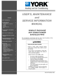
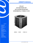
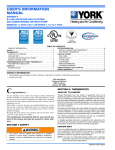
OWNER’S MANUAL
H IG H - E F F IC IE N CY
GA S- FI RE D FU RN A CES
UPFLOW/HORIZONTAL MODELS: P*UR / G9T-UP / FG9-UP
DOWNFLOW MODELS: P*DH / G9T-DH / FG9-DH
CONTENTS
HOW YOUR GAS FURNACE WORKS . . . . 2
KEEP THE FURNACE AREA CLEAR . . . . 2
START-UP AND SHUTDOWN GENERAL
INSTRUCTIONS. . . . . . . . . . . . . . . . . . . . . . 2
FOR YOUR SAFETY, READ BEFORE
OPERATING: . . . . . . . . . . . . . . . . . . . . . . . . 2
WHAT TO DO IF YOU SMELL GAS: . . . . . 2
WARNING: If the information in this manual is not
followed exactly, a fire or explosion may result causing
property damage, personal injury or loss of life.
LIGHTING INSTRUCTIONS . . . . . . . . . . . . 3
SHUTDOWN INSTRUCTIONS . . . . . . . . . . 3
YOUR FURNACE'S FILTER . . . . . . . . . . . . 3
- Do not store or use gasoline or other flammable vapors
and liquids in the vicinity of this or any other appliance.
- WHAT TO DO IF YOU SMELL GAS
FREQUENCY OF CHECKING FILTERS . . 3
• Do not try to light any appliance.
LOCATING / REMOVING FILTERS . . . . . . 3
HOW TO CLEAN YOUR FURNACE'S
FILTER . . . . . . . . . . . . . . . . . . . . . . . . . . . . . 4
MOTOR LUBRICATION . . . . . . . . . . . . . . . 4
• Do not touch any electrical switch; do not use any
phone in your building.
• Immediately call your gas supplier from a neighbor’s
phone. Follow the gas supplier’s instructions.
INSTALLATION & MAINTENANCE
INSTRUCTIONS. . . . . . . . . . . . . . . . . . . . . . 4
FILTER SIZES . . . . . . . . . . . . . . . . . . . . . . . 4
• If you cannot reach your gas supplier, call the fire
department.
- Installation and service must be performed by a qualified installer, service agency or the gas supplier.
035-14379-000 REV C (900)
035-14379-000 REV C (900)
C
ongratulations . . .
On your purchase of one of the most versatile furnaces available in the industry today. This compact, energy-efficient furnace has been precision designed, manufactured of high-quality materials and has passed many rigorous inspections and tests to ensure many years of satisfactory service. This booklet is meant to increase your understanding of your unit, tell you how to operate it efficiently and how to obtain the
greatest measure of comfort at the lowest operating expense. Please read this booklet thoroughly. We appreciate your interest in our product
and your decision to purchase our furnace. Enjoy your comfort.
HOW YOUR GAS FURNACE
WORKS
Your furnace is a very easy appliance to
take for granted. Season after season, it sits
there in your home, keeping you warm and
comfortable. For this reason, you may never
have given much thought to the way your
furnace operates. In order to get the safest
and most efficient operation from your furnace, though, you should understand how
your furnace does its job.
When you set your thermostat to provide
more heat in your home, you are starting the
heating cycle of the furnace. First, the
inducer motor starts to purge the heat
exchanger of any remaining gasses. Next,
the hot surface ignitor glows and after a
warm-up period the gas valve opens and
ignition occurs. A short time later the blower
starts and distributes the warm air throughout the home. When the temperature set on
your thermostat is reached, the gas valve
closes, the main burners are turned off, and
the blower continues to run until the remaining warm air in the system is distributed.
When the blower stops, the heating cycle
has ended.
KEEP THE FURNACE AREA
CLEAR
your home. These materials vaporize easily
and are extremely dangerous.
FOR YOUR SAFETY, READ
BEFORE OPERATING:
NEVER . . .store cleaning materials near
your furnace. Materials such as bleaches,
detergents, powdered cleansers, etc., can
cause corrosion of the heat exchangers.
If you do not follow these instructions exactly, a fire or explosion may
result, causing property damage,
personal injury or loss of life.
Insulating materials may be flammable.
When a furnace is installed in an attic
or other insulated space, or if insulation is added, examine the furnace
area to ensure that the furnace is
kept clear and free of insulation.
A.
This appliance does not have a pilot. It
is equipped with an ignition device
which automatically lights the burners.
Do not try to light the burners by hand.
B.
BEFORE OPERATING, smell all
around the appliance area for gas. Be
sure to smell next to the floor because
some gas is heavier than air and will
settle on the floor.
START-UP AND SHUTDOWN
GENERAL INSTRUCTIONS
WHAT TO DO IF YOU SMELL
GAS:
Read and follow these procedures CAREFULLY and COMPLETELY.
•
Do not try to light any appliance.
•
Do not touch any electrical switch; do
not use any phone in your building.
•
Extinguish any open flame
•
Immediately call your gas supplier from
a neighbor's phone. Follow the gas supplier's instructions.
Before attempting to start your furnace,
always do the following things FIRST:
•
Turn the thermostat OFF.
NEVER . . . use the area around your fur-
•
nace as a storage area for items which
could block the normal flow of air. This flow
of air is required for ventilation of the various
furnace components.
Open windows or make other provisions
to ventilate the area around the furnace.
•
If the blower is running, wait until it shuts
off automatically.
•
If you cannot reach your gas supplier,
call the fire department.
•
Turn off all electrical power to the furnace.
•
•
Make sure all metal surfaces of the furnace have cooled to room temperature
before beginning.
Use only your hand to turn the gas control knob. Never use tools. If the knob
will not turn by hand, don't try to repair it.
Call a qualified service technician. Force
or attempted repair may result in a fire or
explosion.
Do not block or obstruct air openings:
1. On the furnace.
2. Air openings communicating with the
air in which the furnace is installed.
3. The spacings around the furnace.
NEVER. . store flammable materials of
any kind near your furnace. Gasoline, solvents, and other volatile liquids should be
stored only in approved containers outside
2
Do not use this furnace if any part has
been under water. Immediately call a
qualified service technician to inspect
the furnace and to replace any part of
the control system and any gas control which has been underwater.
Unitary Products Group
035-14379-000 REV C (900)
LIGHTING INSTRUCTIONS
SHUTDOWN INSTRUCTIONS
1. STOP! Read all preceding safety
information.
To Turn OFF Gas To Furnace
2. Set the thermostat to lowest setting.
3. Turn OFF all electrical power to the
appliance.
4. This furnace is equipped with an
ignition device which automatically
lights the burners. Do not try to light
the burners by hand.
Should overheating occur, or the gas
supply fail to shut off, shut off the main
manual gas valve to the furnace
before shutting off the electrical supply.
5. Remove the control access panel.
6. Turn gas control switch to "OFF".
7. Wait five (5) minutes to clear out
any gas. If you then smell gas,
STOP! Follow step B in the preceding safety information. If you don't
smell gas, go to the next step.
8. Turn gas control switch to "ON". Do
not force.
9. Replace control access panel.
10.Turn on all electrical power to the
appliance.
FREQUENCY OF CHECKING
FILTERS
Clean your furnace's filter at least every
three months. If you need to replace a filter,
check the filter chart to be sure you install
the right size and type of filter for your furnace.
If your home is new, you should check the
filter every week for the first four weeks after
you begin to use the furnace, and then at
least every three weeks after that, especially
if the system runs constantly.
1. Set thermostat to the lowest setting.
2. Turn off all electrical power to the
furnace if service is to be performed.
3. Remove the control access panel.
4. Turn gas control switch to “OFF”. If
gas valve is equipped with a control
knob, turn knob clockwise to “OFF”
position.
5. Replace the control access panel.
11.Set thermostat to the desired setting.
LOCATING / REMOVING FILTERS
Upflow Furnaces
Most upflow furnaces have their filters
located on the side or bottom of the furnace
in a filter frame.
If your furnace has this type return filter
frame, remove the door by pulling on it.
Slide the filter out of its channel. To replace
after cleaning, slide filter into place and
snap the door on the end of the filter rack.
Some installations may have filters located
in the blower compartment. Check with the
installer for your filter location.
12.The unit will go through a 17-second igniter warm-up period. Then if
the unit does not light within 4 seconds, the unit will go through two
additional cycles before locking out.
13.If the furnace will not operate, follow
the instructions "To Turn OFF Gas
To Furnace" and call your service
technician or gas supplier.
Typical Gas Piping
ON
OFF
Inlet
Outlet
Wrench
Boss
On/Off Switch
Main Regulator
Adjust
Gas Valves - White-Rodgers
36F52-204
YOUR FURNACE'S FILTER WHAT IT DOES
The filter in your furnace takes the lint and
dust out of the air that passes through it.
This keeps dirt particles from getting into the
moving parts of the furnace, where they
could cause serious damage. It also keeps
the dirt from circulating through your home.
As the filter continues to collect these particles, it becomes clogged and no longer
allows enough air to circulate through the
furnace. If this happens, the heat exchangers and blower motor could overheat; a
potentially dangerous situation. It is very
important to keep the air filter clean! Never
operate your furnace without a suitable air
filter.
Upflow Furnace Internal Filter
Applications
To check filters located in the blower compartment, remove th upper furnace door by
lifting up. Pull out bottom of door and lower
from furnace. Remove th blower compartment panel by lifting up.
Note:The spring-loaded safety cutoff switch,
mounted under the blower deck will automatically cut off the electrical power supply
to the furnace when the blower panel is
removed.
To remove bottom mounted filter (s) on all
furnaces, push the looped end of the filter
retainer to the side and then lift up. Reverse
the procedure to reinstall filters.
Unitary Products Group
3
035-14379-000 REV C (900)
Downflow/Horizontal Models
The filters in your downflow/horizontal furnace are located in the plenum or ductwork
above the furnace.To check the filters, turn
off the electrical supply to the furnace. Then
remove the access panel and lift the filter(s)
off the rack.
NOTE:The spring-loaded safety cutoff
switch, mounted to the blower deck will
automatically cut off the electrical supply to
the furnace when the blower access door is
removed.
RETURN
AIR
DUCT
VENT PIPE
HOW TO CLEAN YOUR
FURNACE'S FILTER
MOTOR LUBRICATION
The motors in these furnaces are permanently lubricated, and require no periodic oiling.
INSTALLATION & MAINTENANCE
INSTRUCTIONS
It is the owner’s responsibility to ensure that
an annual inspection of the entire heating
portion of the unit is made by a qualified service agency.
ACCESS
PANEL
The inspection should include heating element, vent/combustion air piping, to see that
they are clear and free of obstructions and
without holes or corrosion.
FURNACE
Make sure the horizontal run of the vent system slopes upward and all of the connections are secure.
Downflow Furnace - Typical Filter
Location
Horizontal Furnaces
Most horizontal furnaces have their filters
located ina filter grille(s) so that it may be
easily changed without gaining access to
the attic or crawl space.
Some installations may have a filter rack
near the furnace. With this type of accessory, unsnap the filter rack door and pull.
The filter is attached to the door and will
slide out. If you are unsure where the furnace filter is installed, check with the
installer.
Make sure the return air duct connections
are physically sound and sealed to the furnace casing and terminates outside the
space containing the furnace. Make sure no
sagging, cracks, gaps, etc. exist around the
base of the furnace.
•
Check for dust and lint on the sensor
and main burners.
•
Check combustion air and vent pipe for
blockage, corrosion or leakage.
•
Check all components to be sure they
are in good condition and that there are
no obvious signs of deterioration.
If all components appear to be in good operating condition, turn the gas control to the
ON position after replacing the front panel of
the burner box. Replace the front panels.
Restore gas and power supplies to the furnace, and set thermostat to the desired temperature.
If, during your inspection of your furnace,
you find any of the following conditions, do
not operate the furnace:
•
Excessive amounts of dust and lint on
components.
•
Damaged or deteriorated components or
surfaces.
•
Leaks or blockage in the vent pipe passages.
Check the main burner flames for proper
adjustment per the illustration below:
COMBUSTION AIR
INTAKE
BURNER
FLAME
Call a certified dealer/servicing contractor to
check your furnace, or for more information
if you have questions about the operation of
your furnace.
FILTER SIZES
MANIFOLD
MAIN
BURNER
INNER
FLAME
CONES
Proper Burner Flame Appearance
FURNACE
Before proceeding, be sure the area
is well ventilated. Turn the thermostat OFF. If the blower is running,
wait until it stops automatically. Turn
OFF the gas and electrical power
supplies to the furnace. Check all
metal parts and surfaces to be sure
they have cooled to room temperature before you begin.
High-velocity filters may be cleaned with a
vacuum cleaner or washed with a garden
hose. Be sure to shake off excess water
before re-installing the filter.
RETURN AIR DUCT
Routine periodic maintenance checks
should be done on your furnace at least
every time you check the filters.
Remove the front panels and the panel on
the front of the burner box after turning the
knob on the gas control to the OFF position.
Check the following items:
Horizontal Furnace - Typical Filter
Location
Subject to change without notice. Printed in U.S.A.
Copyright © by Unitary Products Group 2000. All rights reserved.
Unitary
5005
Products
York
Group
Drive
UPFLOW MODELS
SIDE
BOTTOM
40/37/1000/A
60/55/1000/B
80/75/1200/B
80/75/1600/C
100/95/1400/C
100/95/2000/C
120/112/2000/D
140/130/2000/D
16 x 25
16 x 25
16 x 25
16 x 25
16 x 25
(2) 16 x 25
(2) 16 x 25
(2) 16 x 25
14 x 25
16 x 25
16 x 25
20 x 25
20 x 25
20 x 25
22 x 25
22 x 25
DOWNFLOW /
HORIZONTAL
MODELS
FILTER SIZE
All Models
(2) 14 x 25
035-14379-000 REV C (900)
Supersedes: 035-14379-000 REV B (900)
Norman
OK
73069