1
Cisco XR 12000 Series Router SIP and SPA
Software Configuration Guide, Release 3.2
January 9, 2006
Corporate Headquarters
Cisco Systems, Inc.
170 West Tasman Drive
San Jose, CA 95134-1706
USA
http://www.cisco.com
Tel: 408 526-4000
800 553-NETS (6387)
Fax: 408 526-4100
Text Part Number: OL-9177-01
THE SPECIFICATIONS AND INFORMATION REGARDING THE PRODUCTS IN THIS MANUAL ARE SUBJECT TO CHANGE WITHOUT NOTICE. ALL
STATEMENTS, INFORMATION, AND RECOMMENDATIONS IN THIS MANUAL ARE BELIEVED TO BE ACCURATE BUT ARE PRESENTED WITHOUT
WARRANTY OF ANY KIND, EXPRESS OR IMPLIED. USERS MUST TAKE FULL RESPONSIBILITY FOR THEIR APPLICATION OF ANY PRODUCTS.
THE SOFTWARE LICENSE AND LIMITED WARRANTY FOR THE ACCOMPANYING PRODUCT ARE SET FORTH IN THE INFORMATION PACKET THAT
SHIPPED WITH THE PRODUCT AND ARE INCORPORATED HEREIN BY THIS REFERENCE. IF YOU ARE UNABLE TO LOCATE THE SOFTWARE LICENSE
OR LIMITED WARRANTY, CONTACT YOUR CISCO REPRESENTATIVE FOR A COPY.
The Cisco implementation of TCP header compression is an adaptation of a program developed by the University of California, Berkeley (UCB) as part of UCB’s public
domain version of the UNIX operating system. All rights reserved. Copyright © 1981, Regents of the University of California.
NOTWITHSTANDING ANY OTHER WARRANTY HEREIN, ALL DOCUMENT FILES AND SOFTWARE OF THESE SUPPLIERS ARE PROVIDED “AS IS” WITH
ALL FAULTS. CISCO AND THE ABOVE-NAMED SUPPLIERS DISCLAIM ALL WARRANTIES, EXPRESSED OR IMPLIED, INCLUDING, WITHOUT
LIMITATION, THOSE OF MERCHANTABILITY, FITNESS FOR A PARTICULAR PURPOSE AND NONINFRINGEMENT OR ARISING FROM A COURSE OF
DEALING, USAGE, OR TRADE PRACTICE.
IN NO EVENT SHALL CISCO OR ITS SUPPLIERS BE LIABLE FOR ANY INDIRECT, SPECIAL, CONSEQUENTIAL, OR INCIDENTAL DAMAGES, INCLUDING,
WITHOUT LIMITATION, LOST PROFITS OR LOSS OR DAMAGE TO DATA ARISING OUT OF THE USE OR INABILITY TO USE THIS MANUAL, EVEN IF CISCO
OR ITS SUPPLIERS HAVE BEEN ADVISED OF THE POSSIBILITY OF SUCH DAMAGES.
CCIP, CCSP, the Cisco Arrow logo, the Cisco Powered Network mark, Cisco Unity, Follow Me Browsing, FormShare, and StackWise are trademarks of Cisco Systems, Inc.;
Changing the Way We Work, Live, Play, and Learn, and iQuick Study are service marks of Cisco Systems, Inc.; and Aironet, ASIST, BPX, Catalyst, CCDA, CCDP, CCIE, CCNA,
CCNP, Cisco, the Cisco Certified Internetwork Expert logo, Cisco IOS, the Cisco IOS logo, Cisco Press, Cisco Systems, Cisco Systems Capital, the Cisco Systems logo,
Empowering the Internet Generation, Enterprise/Solver, EtherChannel, EtherSwitch, Fast Step, GigaStack, Internet Quotient, IOS, IP/TV, iQ Expertise, the iQ logo, iQ Net
Readiness Scorecard, LightStream, MGX, MICA, the Networkers logo, Networking Academy, Network Registrar, Packet, PIX, Post-Routing, Pre-Routing, RateMUX, Registrar,
ScriptShare, SlideCast, SMARTnet, StrataView Plus, Stratm, SwitchProbe, TeleRouter, The Fastest Way to Increase Your Internet Quotient, TransPath, and VCO are registered
trademarks of Cisco Systems, Inc. and/or its affiliates in the United States and certain other countries.
All other trademarks mentioned in this document or Website are the property of their respective owners. The use of the word partner does not imply a partnership relationship
between Cisco and any other company. (0401R)
Cisco XR 12000 Series Router SIP and SPA Software Configuration Guide, Release 3.2
Copyright © 2006 Cisco Systems, Inc. All rights reserved.
CONTENTS
Preface
xi
Document Change History
Objectives
xi
xi
Organization
xii
Related Documentation xiii
Cisco XR 12000 Series Router Documentation
Cisco IOS-XR Software Publications xiii
Document Conventions
xiii
xiv
Obtaining Documentation xv
Cisco.com xv
Documentation DVD xv
Ordering Documentation xvi
Documentation Feedback
xvi
Cisco Product Security Overview xvi
Reporting Security Problems in Cisco Products
xvii
Obtaining Technical Assistance xvii
Cisco Technical Support Website xvii
Submitting a Service Request xviii
Definitions of Service Request Severity xviii
Obtaining Additional Publications and Information
SIP and SPA Product Overview
xix
1-1
Introduction to SIPs and SPAs 1-1
SPA Interface Processors 1-1
Shared Port Adapters 1-2
SIP and SPA Compatibility
SPA Optics Compatibility
1-3
1-3
SPA Interface Addresses on Cisco XR 12000 Series Routers
SIP Software and Hardware Compatibility
1-5
Overview of the Cisco XR 12000 Series Router SIPs
Release History
2-1
2-1
Cisco 12000 SIP-600 Features
Supported MIBs
1-4
2-1
2-3
Cisco XR 12000 Series Router SIP and SPA Software Configuration Guide, Release 3.2
Release 3.2, OL-9177-01 Rev. A1, January 6, 2006
iii
Contents
Displaying the SPA Hardware Type 2-6
Example of the show inventory Command
2-7
Gigabit Ethernet Shared Port Adapters
Overview of the Gigabit Ethernet SPAs
Release History
3-1
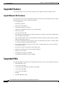
Supported Features 3-2
Gigabit Ethernet SPA Features
Supported MIBs
3-1
3-2
3-2
SPA Architecture 3-3
Path of a Packet in the Ingress Direction 3-3
Path of a Packet in the Egress Direction 3-4
Displaying the SPA Hardware Type 3-4
Example of the show inventory Command 3-4
Example of the show hw-module subslot Command
Configuring Ethernet SPAs on Cisco IOS XR Software
3-5
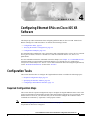
4-1
Configuration Tasks 4-1
Required Configuration Steps 4-1
Specifying the Interface Address 4-4
Configuring a Basic Ethernet Interface 4-5
Verifying the Interface Configuration
4-9
Configuration Examples 4-10
Configuring an Ethernet Interface Example 4-10
Configuring MAC Accounting Example 4-11
Packet over SONET Shared Port Adapters
Overview of Packet over SONET SPAs
Release History
5-1
5-1
Supported Features 5-1
Cisco 12000 SIP-600 Features 5-1
1-Port OC-192c/STM-64 POS/RPR XFP SPA Features
Restrictions
5-2
5-3
Supported MIBs
5-3
SPA Architecture 5-3
1-Port OC-192c/STM-64 POS/RPR XFP SPA Architecture
Displaying the SPA Hardware Type
5-4
5-5
Cisco XR 12000 Series Router SIP and SPA Software Configuration Guide, Release 3.2
iv
Release 3.2, OL-9177-01 Rev. A1, January 6, 2006
Contents
Example of the show inventory Command 5-5
Example of the show hw-module Command 5-6
Configuring POS SPAs on Cisco IOS XR Software
6-1
Configuration Tasks 6-1
Specifying the Interface Address 6-2
Configuring a SONET Controller 6-3
Configuring SONET APS 6-6
Configuring Fast Reroute and SONET APS 6-10
Configuring a POS Interface 6-12
Configuring Cisco HDLC on a POS Interface 6-15
Configuring PPP on a POS Interface 6-17
Verifying the Interface Configuration
6-20
Configuration Examples 6-20
SONET Controller Configuration Example 6-21
SONET APS Group Configuration Example 6-21
Configuring Basic POS Example 6-22
Configuring PPP Example 6-23
Field-Programmable Devices
Upgrading Field-Programmable Devices
7-1
Overview of SPA FPD Image Upgrade Support
7-1
Upgrading SPA FPD Images 7-2
Verifying SPA FPD Image Compatibility 7-2
SPA FPD Image Upgrade 7-4
SPA FPD Image Upgrade Task List 7-5
SPA FPD Image Upgrade Example 7-6
Troubleshooting Problems with SPA FPD Image Upgrades 7-6
Power Failure or Removal of a SPA During an FPD Image Upgrade
FPD Command Summary
7-6
7-8
Shared Port Adapter Command Reference
Command Summary for the Gigabit Ethernet SPA
Command Summary for the POS SPAs
Command Reference
8-1
9-1
10-1
hw-module subslot power-cycle
10-2
Cisco XR 12000 Series Router SIP and SPA Software Configuration Guide, Release 3.2
Release 3.2, OL-9177-01 Rev. A1, January 6, 2006
v
Contents
hw-module subslot reload
10-3
hw-module subslot shutdown
show fpd package
10-4
10-6
show hw-module fpd
10-8
show hw-module subslot brief
10-10
show hw-module subslot config
show hw-module subslot counters
show hw-module subslot errors
show hw-module subslot registers
show hw-module subslot status
upgrade hw-module fpd
10-13
10-15
10-18
10-20
10-22
10-24
GLOSSARY
INDEX
Cisco XR 12000 Series Router SIP and SPA Software Configuration Guide, Release 3.2
vi
Release 3.2, OL-9177-01 Rev. A1, January 6, 2006
F I G U R E S
Figure 1-1
Single-height and Double-height SPA Sizes
Figure 1-2
Horizontal and Vertical Chassis Slot Orientation for SPAs
Figure 1-3
Slot, Subslot, and Port Locations for the 1-Port 10-Gigabit Ethernet SPA and 10-Port Gigabit Ethernet SPA
Figure 4-1
Slot, Subslot, and Port Locations on the Cisco 12000 SIP-600
Figure 5-1
1-Port OC-192c/STM-64 POS/RPR XFP SPA Architecture
Figure 6-1
Slot, Subslot, and Port Locations for the 1-Port OC-192c/STM-64 POS/RPR XFP SPA
1-2
1-2
4-5
5-4
6-2
Cisco XR 12000 Series Router SIP and SPA Software Configuration Guide, Release 3.2
Release 3.2, OL-9177-01 Rev. A1, January 6, 2006
vii
1-4
Figures
Cisco XR 12000 Series Router SIP and SPA Software Configuration Guide, Release 3.2
viii
Release 3.2, OL-9177-01 Rev. A1, January 6, 2006
T A B L E S
Table 1
Document Change History Table
Table 1-1
SIP and SPA Compatibility on the Cisco XR 12000 Series Router
Table 1-2
SPA Optics Compatibility
Table 1-3
SIP Hardware and Software Compatibility
Table 2-1
Release History for SIP Hardware
Table 2-2
SPA Hardware Descriptions in show Commands
Table 3-1
Release History for Ethernet SPA
Table 3-2
SPA Hardware Descriptions in show Commands
Table 3-3
show inventory Field Descriptions
Table 3-4
show hw-module subslot brief Field Descriptions
Table 4-1
Ethernet SPA Default Configuration Values
Table 5-1
Hardware Release History
Table 5-2
SPA Hardware Description in show Commands
Table 5-3
show inventory Field Descriptions
Table 5-4
show hw-module subslot brief Field Descriptions
Table 6-1
POS SPA and SIP Default Interface Settings
Table 7-1
show hw-module fpd Field Descriptions
Table 7-2
show fpd package Field Descriptions
Table 7-3
FPD Command Summary
Table 8-1
Command Summary
8-1
Table 9-1
Command Summary
9-1
Table 10-1
show fpd package Field Descriptions
Table 10-2
show hw-module fpd Field Descriptions
Table 10-3
show hw-module subslot brief Field Descriptions
Table 10-4
show hw-module subslot config Field Descriptions
Table 10-5
show hw-module subslot counters Field Descriptions
xi
1-3
1-3
1-5
2-1
2-6
3-1
3-4
3-5
3-5
4-6
5-1
5-5
5-5
5-6
6-12
7-3
7-4
7-8
10-7
10-9
10-11
10-14
10-16
Cisco XR 12000 Series Router SIP and SPA Software Configuration Guide, Release 3.2
Release 3.2, OL-9177-01 Rev. A1, January 6, 2006
ix
Tables
Cisco XR 12000 Series Router SIP and SPA Software Configuration Guide, Release 3.2
x
Release 3.2, OL-9177-01 Rev. A1, January 6, 2006
Preface
This preface describes the objectives and organization of this document and explains how to find
additional information on related products and services. This preface contains the following sections:
•
Document Change History, page xi
•
Objectives, page xi
•
Organization, page xii
•
Related Documentation, page xiii
•
Document Conventions, page xiv
•
Obtaining Documentation, page xv
Document Change History
Table 1 provides a list of the changes to this document.
Table 1
Document Change History Table
Release No.
Revision
Date
Change Summary
3.2
Release 3.2,
OL-9177-01
Rev. A1,
January 6,
2006
May 10, 2005
Initial Release and 1st publication. Provided the IOS XR commands
and configuration procedures for the following SPAs when they are
installed in a Cisco 12000 SIP-600:
•
1-Port 10-Gigabit Ethernet SPA
•
5-Port Gigabit Ethernet SPA
•
10-Port Gigabit Ethernet SPA
•
1-Port OC-192c/STM-64 POS/RPR XFP SPA
Objectives
This document describes the configuration and troubleshooting of SPA interface processors (SIPs) and
shared port adapters (SPAs) that are supported on a Cisco XR 12000 Series Router.
Cisco XR 12000 Series Router SIP and SPA Software Configuration Guide, Release 3.2
Release 3.2, OL-9177-01 Rev. A1, January 6, 2006
xi
Organization
This document contains the following chapters:
Chapter
Title
Description
Chapter 1
SIP and SPA Product Overview
Provides a brief introduction to the SIP and SPA
architecture on Cisco 12000 Series Routers.
Chapter 2
Overview of the Cisco XR 12000
Series Router SIPs
Provides an overview of the release history, and
feature and Management Information Base (MIB)
support for the SIPs supported on Cisco 12000 Series
Routers.
Part 1
Gigabit Ethernet Shared Port
Adapters
Gigabit Ethernet Section
Chapter 3
Overview of the Gigabit Ethernet
SPAs
Provides an overview of the Gigabit Ethernet SPAs.
Chapter 4
Configuring Ethernet SPAs on
Cisco IOS XR Software
Provides information about configuring the Cisco
1-port 10 Gigabit Ethernet SPA and Cisco 10-port
Gigabit Ethernet SPA on Cisco XR 12000 Series
Routers.
Part 2
Packet over SONET Shared Port
Adapters
Packet over SONET (POS) Section
Chapter 5
Overview of Packet over SONET
SPAs
Provides an overview of the POS SPAs
Chapter 6
Configuring POS SPAs on Cisco
IOS XR Software
Provides information about configuring POS SPAs on
Cisco XR 12000 Series Routers running Cisco
IOS XR software.
Part 3
Field-Programmable Devices
Field-Programmable Devices (FPD) Section
Chapter 7
Upgrading Field-Programmable
Devices
Provides information about upgrading the
Field-Programmable Gate Array (FPGA) on Cisco
XR 12000 Series Routers.
Part 4
Shared Port Adapter Command
Reference
Command Reference Section
Chapter 8
Command Summary for the
Gigabit Ethernet SPA
Provides an alphabetical list of some of the related
commands to configure, monitor, and maintain
Gigabit Ethernet SPAs.
Chapter 9
Command Summary for the POS
SPAs
Provides an alphabetical list of some of the related
commands to configure, monitor, and maintain POS
SPAs.
Chapter 10 Command Reference
Describes Cisco IOS-XR software command
reference information including syntax, usage
guidelines, and examples for all new and modified
commands for SPAs on Cisco XR 12000 Series
Routers.
Cisco XR 12000 Series Router SIP and SPA Software Configuration Guide, Release 3.2
xii
Release 3.2, OL-9177-01 Rev. A1, January 6, 2006
Related Documentation
This section refers you to other documentation that also might be useful as you configure your Cisco XR
12000 Series Router. The documentation listed below is available online.
•
Cisco 12000 Series Router SIP and SPA Hardware Installation Guide
•
Cisco 12000 Series Router SIP and SPA Software Configuration Guide (Cisco IOS)
•
Cisco XR 12000 Series Router SIP and SPA Software Configuration Guide
•
Cisco IOS Release Release Notes for Cisco 12000 Series Routers
•
Regulatory Compliance and Safety Information for Cisco 12000 Series Routers
•
Cisco IOS XR Getting Started Guide
Cisco XR 12000 Series Router Documentation
As you configure SIPs and SPAs on your Cisco XR 12000 Series Router, you should also refer to the
following companion publication for important hardware installation information:
•
Cisco 12000 Series Router SIP and SPA Hardware Installation Guide
Some of the other Cisco XR 12000 Series Router publications might be useful to you as you configure
your Cisco XR 12000 Series Router. The following URL provides a wide range of documentation for
the various Cisco XR 12000 Series Routers and their accompanying field replaceable units (FRUs):
http://www.cisco.com/univercd/cc/td/doc/product/core/cis12000/
Several other publications are also related to the Cisco XR 12000 Series Router. For a complete
reference of related documentation, refer to the various roadmap documents located at the following
URL:
http://www.cisco.com/univercd/cc/td/doc/product/core/cis12000/roadmap/
Cisco IOS-XR Software Publications
Your router, switch, or gateway and the Cisco IOS-XR software running on it contain extensive features.
You can find documentation for Cisco IOS-XR software features at the following URL:
http://www.cisco.com/univercd/cc/td/doc/product/software/
Cisco IOS-XR Release 3.2.0 Software Publications
Documentation for Cisco IOS-XR Release 3.2.0, including release notes and system error messages, can
be found at the following URL:
http://www.cisco.com/univercd/cc/td/doc/product/software/iosxr3/index.htm
Cisco XR 12000 Series Router SIP and SPA Software Configuration Guide, Release 3.2
Release 3.2, OL-9177-01 Rev. A1, January 6, 2006
xiii
Document Conventions
Within the SIP and SPA software configuration guides, the term router is generally used to refer to a
variety of Cisco products (for example, routers, access servers, and switches). Routers, access servers,
and other networking devices that support Cisco IOS-XR software are shown interchangeably within
examples. These products are used only for illustrative purposes; that is, an example that shows one
product does not necessarily indicate that other products are not supported.
This documentation uses the following conventions:
Convention
Description
^ or Ctrl
The ^ and Ctrl symbols represent the Control key. For example, the key combination ^D or Ctrl-D
means hold down the Control key while you press the D key. Keys are indicated in capital letters but
are not case sensitive.
string
A string is a nonquoted set of characters shown in italics. For example, when setting an SNMP
community string to public, do not use quotation marks around the string or the string will include the
quotation marks.
Command syntax descriptions use the following conventions:
Convention
Description
bold
Bold text indicates commands and keywords that you enter literally as shown.
italics
Italic text indicates arguments for which you supply values.
[x]
Square brackets enclose an optional element (keyword or argument).
|
A vertical line indicates a choice within an optional or required set of keywords or arguments.
[x | y]
Square brackets enclosing keywords or arguments separated by a vertical line indicate an optional
choice.
{x | y}
Braces enclosing keywords or arguments separated by a vertical line indicate a required choice.
Nested sets of square brackets or braces indicate optional or required choices within optional or required
elements. For example:
Convention
Description
[x {y | z}]
Braces and a vertical line within square brackets indicate a required choice within an optional element.
Examples use the following conventions:
Convention
Description
screen
Examples of information displayed on the screen are set in Courier font.
bold screen
Examples of text that you must enter are set in Courier bold font.
<
Angle brackets enclose text that is not printed to the screen, such as passwords.
>
Cisco XR 12000 Series Router SIP and SPA Software Configuration Guide, Release 3.2
xiv
Release 3.2, OL-9177-01 Rev. A1, January 6, 2006
Convention
Description
!
An exclamation point at the beginning of a line indicates a comment line. (Exclamation points are also
displayed by the Cisco IOS-XR software for certain processes.)
[
]
Square brackets enclose default responses to system prompts.
The following conventions are used to attract the attention of the reader:
Caution
Note
Means reader be careful. In this situation, you might do something that could result in equipment
damage or loss of data.
Means reader take note. Notes contain helpful suggestions or references to materials not contained
in this manual.
Obtaining Documentation
Cisco documentation and additional literature are available on Cisco.com. Cisco also provides several
ways to obtain technical assistance and other technical resources. These sections explain how to obtain
technical information from Cisco Systems.
Cisco.com
You can access the most current Cisco documentation at this URL:
http://www.cisco.com/univercd/home/home.htm
You can access the Cisco website at this URL:
http://www.cisco.com
You can access international Cisco websites at this URL:
http://www.cisco.com/public/countries_languages.shtml
Documentation DVD
Cisco documentation and additional literature are available in a Documentation DVD package, which
may have shipped with your product. The Documentation DVD is updated regularly and may be more
current than printed documentation. The Documentation DVD package is available as a single unit.
Registered Cisco.com users (Cisco direct customers) can order a Cisco Documentation DVD (product
number DOC-DOCDVD=) from the Ordering tool or Cisco Marketplace.
Cisco Ordering tool:
http://www.cisco.com/en/US/partner/ordering/
Cisco Marketplace:
http://www.cisco.com/go/marketplace/
Cisco XR 12000 Series Router SIP and SPA Software Configuration Guide, Release 3.2
Release 3.2, OL-9177-01 Rev. A1, January 6, 2006
xv
Ordering Documentation
You can find instructions for ordering documentation at this URL:
http://www.cisco.com/univercd/cc/td/doc/es_inpck/pdi.htm
You can order Cisco documentation in these ways:
•
Registered Cisco.com users (Cisco direct customers) can order Cisco product documentation from
the Ordering tool:
http://www.cisco.com/en/US/partner/ordering/
•
Nonregistered Cisco.com users can order documentation through a local account representative by
calling Cisco Systems Corporate Headquarters (California, USA) at 408 526-7208 or, elsewhere in
North America, by calling 1 800 553-NETS (6387).
Documentation Feedback
You can send comments about technical documentation to [email protected].
You can submit comments by using the response card (if present) behind the front cover of your
document or by writing to the following address:
Cisco Systems
Attn: Customer Document Ordering
170 West Tasman Drive
San Jose, CA 95134-9883
We appreciate your comments.
Cisco Product Security Overview
Cisco provides a free online Security Vulnerability Policy portal at this URL:
http://www.cisco.com/en/US/products/products_security_vulnerability_policy.html
From this site, you can perform these tasks:
•
Report security vulnerabilities in Cisco products.
•
Obtain assistance with security incidents that involve Cisco products.
•
Register to receive security information from Cisco.
A current list of security advisories and notices for Cisco products is available at this URL:
http://www.cisco.com/go/psirt
If you prefer to see advisories and notices as they are updated in real time, you can access a Product
Security Incident Response Team Really Simple Syndication (PSIRT RSS) feed from this URL:
http://www.cisco.com/en/US/products/products_psirt_rss_feed.html
Cisco XR 12000 Series Router SIP and SPA Software Configuration Guide, Release 3.2
xvi
Release 3.2, OL-9177-01 Rev. A1, January 6, 2006
Reporting Security Problems in Cisco Products
Cisco is committed to delivering secure products. We test our products internally before we release them,
and we strive to correct all vulnerabilities quickly. If you think that you might have identified a
vulnerability in a Cisco product, contact PSIRT:
Tip
•
Emergencies — [email protected]
•
Nonemergencies — [email protected]
We encourage you to use Pretty Good Privacy (PGP) or a compatible product to encrypt any sensitive
information that you send to Cisco. PSIRT can work from encrypted information that is compatible with
PGP versions 2.x through 8.x.
Never use a revoked or an expired encryption key. The correct public key to use in your correspondence
with PSIRT is the one that has the most recent creation date in this public key server list:
http://pgp.mit.edu:11371/pks/lookup?search=psirt%40cisco.com&op=index&exact=on
In an emergency, you can also reach PSIRT by telephone:
•
1 877 228-7302
•
1 408 525-6532
Obtaining Technical Assistance
For all customers, partners, resellers, and distributors who hold valid Cisco service contracts, Cisco
Technical Support provides 24-hour-a-day, award-winning technical assistance. The Cisco Technical
Support Website on Cisco.com features extensive online support resources. In addition, Cisco Technical
Assistance Center (TAC) engineers provide telephone support. If you do not hold a valid Cisco service
contract, contact your reseller.
Cisco Technical Support Website
The Cisco Technical Support Website provides online documents and tools for troubleshooting and
resolving technical issues with Cisco products and technologies. The website is available 24 hours a day,
365 days a year, at this URL:
http://www.cisco.com/techsupport
Access to all tools on the Cisco Technical Support Website requires a Cisco.com user ID and password.
If you have a valid service contract but do not have a user ID or password, you can register at this URL:
http://tools.cisco.com/RPF/register/register.do
Note
Use the Cisco Product Identification (CPI) tool to locate your product serial number before submitting
a web or phone request for service. You can access the CPI tool from the Cisco Technical Support
Website by clicking the Tools & Resources link under Documentation & Tools. Choose Cisco Product
Identification Tool from the Alphabetical Index drop-down list, or click the Cisco Product
Identification Tool link under Alerts & RMAs. The CPI tool offers three search options: by product ID
Cisco XR 12000 Series Router SIP and SPA Software Configuration Guide, Release 3.2
Release 3.2, OL-9177-01 Rev. A1, January 6, 2006
xvii
or model name; by tree view; or for certain products, by copying and pasting show command output.
Search results show an illustration of your product with the serial number label location highlighted.
Locate the serial number label on your product and record the information before placing a service call.
Submitting a Service Request
Using the online TAC Service Request Tool is the fastest way to open S3 and S4 service requests. (S3
and S4 service requests are those in which your network is minimally impaired or for which you require
product information.) After you describe your situation, the TAC Service Request Tool provides
recommended solutions. If your issue is not resolved using the recommended resources, your service
request is assigned to a Cisco TAC engineer. The TAC Service Request Tool is located at this URL:
http://www.cisco.com/techsupport/servicerequest
For S1 or S2 service requests or if you do not have Internet access, contact the Cisco TAC by telephone.
(S1 or S2 service requests are those in which your production network is down or severely degraded.)
Cisco TAC engineers are assigned immediately to S1 and S2 service requests to help keep your business
operations running smoothly.
To open a service request by telephone, use one of the following numbers:
Asia-Pacific: +61 2 8446 7411 (Australia: 1 800 805 227)
EMEA: +32 2 704 55 55
USA: 1 800 553-2447
For a complete list of Cisco TAC contacts, go to this URL:
http://www.cisco.com/techsupport/contacts
Definitions of Service Request Severity
To ensure that all service requests are reported in a standard format, Cisco has established severity
definitions.
Severity 1 (S1)—Your network is “down,” or there is a critical impact to your business operations. You
and Cisco will commit all necessary resources around the clock to resolve the situation.
Severity 2 (S2)—Operation of an existing network is severely degraded, or significant aspects of your
business operation are negatively affected by inadequate performance of Cisco products. You and Cisco
will commit full-time resources during normal business hours to resolve the situation.
Severity 3 (S3)—Operational performance of your network is impaired, but most business operations
remain functional. You and Cisco will commit resources during normal business hours to restore service
to satisfactory levels.
Severity 4 (S4)—You require information or assistance with Cisco product capabilities, installation, or
configuration. There is little or no effect on your business operations.
Cisco XR 12000 Series Router SIP and SPA Software Configuration Guide, Release 3.2
xviii
Release 3.2, OL-9177-01 Rev. A1, January 6, 2006
Obtaining Additional Publications and Information
Information about Cisco products, technologies, and network solutions is available from various online
and printed sources.
•
Cisco Marketplace provides a variety of Cisco books, reference guides, and logo merchandise. Visit
Cisco Marketplace, the company store, at this URL:
http://www.cisco.com/go/marketplace/
•
Cisco Press publishes a wide range of general networking, training and certification titles. Both new
and experienced users will benefit from these publications. For current Cisco Press titles and other
information, go to Cisco Press at this URL:
http://www.ciscopress.com
•
Packet magazine is the Cisco Systems technical user magazine for maximizing Internet and
networking investments. Each quarter, Packet delivers coverage of the latest industry trends,
technology breakthroughs, and Cisco products and solutions, as well as network deployment and
troubleshooting tips, configuration examples, customer case studies, certification and training
information, and links to scores of in-depth online resources. You can access Packet magazine at
this URL:
http://www.cisco.com/packet
•
iQ Magazine is the quarterly publication from Cisco Systems designed to help growing companies
learn how they can use technology to increase revenue, streamline their business, and expand
services. The publication identifies the challenges facing these companies and the technologies to
help solve them, using real-world case studies and business strategies to help readers make sound
technology investment decisions. You can access iQ Magazine at this URL:
http://www.cisco.com/go/iqmagazine
•
Internet Protocol Journal is a quarterly journal published by Cisco Systems for engineering
professionals involved in designing, developing, and operating public and private internets and
intranets. You can access the Internet Protocol Journal at this URL:
http://www.cisco.com/ipj
•
World-class networking training is available from Cisco. You can view current offerings at
this URL:
http://www.cisco.com/en/US/learning/index.html
Cisco XR 12000 Series Router SIP and SPA Software Configuration Guide, Release 3.2
Release 3.2, OL-9177-01 Rev. A1, January 6, 2006
xix
Cisco XR 12000 Series Router SIP and SPA Software Configuration Guide, Release 3.2
xx
Release 3.2, OL-9177-01 Rev. A1, January 6, 2006
C H A P T E R
1
SIP and SPA Product Overview
This chapter provides an introduction to modular services cards (SIPs) and shared port adapters (SPAs).
It includes the following sections:
•
Introduction to SIPs and SPAs, page 1-1
•
SIP and SPA Compatibility, page 1-3
•
SPA Optics Compatibility, page 1-3
•
SPA Interface Addresses on Cisco XR 12000 Series Routers, page 1-4
•
SIP Software and Hardware Compatibility, page 1-5
For more hardware details for the specific SIP and SPAs that are supported on the Cisco XR 12000 Series
Router, refer to the companion publication, Cisco XR 12000 Series Router SIP and SPA Hardware
Installation Guide, Release 3.2.
Introduction to SIPs and SPAs
SIPs and SPAs are a new carrier card and port adapter architecture to increase modularity, flexibility, and
density across Cisco Systems routers for network connectivity. This section describes the SIPs and SPAs
and provides some guidelines for their use.
SPA Interface Processors
The following list describes some of the general characteristics of a SIP:
•
A SIP is a carrier card that inserts into a router slot like a line card. It provides no network
connectivity on its own.
•
A SIP can contain two or more subslots, which are used to house one or more SPAs. The SPA
provides interface ports for network connectivity.
•
During normal operation the SIP should reside in the router fully populated either with functional
SPAs in all subslots, or with a blank filler panel inserted in any empty subslots.
•
SIPs support online insertion and removal (OIR) while SPAs are inserted in their subslots.
Cisco XR 12000 Series Router SIP and SPA Software Configuration Guide, Release 3.2
Release 3.2, OL-6396-01, Rev.A1 January 9, 2006
1-1
Chapter 1
SIP and SPA Product Overview
Introduction to SIPs and SPAs
Shared Port Adapters
The following list describes some of the general characteristics of a SPA:
•
A SPA is a modular type of port adapter that inserts into a subslot of a compatible SIP carrier card
to provide network connectivity and increased interface port density. A SIP can hold one or more
SPAs, depending on the SIP type.
•
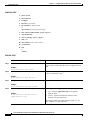
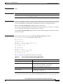
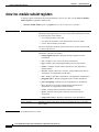
SPAs are available in the following sizes, as shown in Figure 1-1 and Figure 1-2:
– Single-width, single-height SPA—Inserts into a single SIP subslot.
– Single-width, double-height SPA—Inserts into two single, vertically aligned SIP subslots.
– Double-width, single-height SPA—Inserts into a two single, horizontally aligned SIP subslots.
– Double-width, double-height SPA—Inserts into all four SIP subslots, or the entire SPA
enclosure.
Figure 1-1
Single-height and Double-height SPA Sizes
Front of SIP
Single-height SPA
116886
Double-height SPA
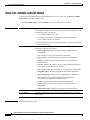
Horizontal and Vertical Chassis Slot Orientation for SPAs
Front of SIP, horizontal chassis slots
SPA 0
SPA 1
Double-height SPA
SPA 3
SPA 0
SPA 2
SPA 1
Double-height SPA
SPA 1
SPA 3
SPA 0
SPA 2
SPA 3
SPA 1
SPA 2
SPA 0
Vertical slot orientation
116887
Figure 1-2
Cisco XR 12000 Series Router SIP and SPA Software Configuration Guide, Release 3.2
1-2
Release 3.2, OL-6396-01, Rev.A1 January 9, 2006
Chapter 1
SIP and SPA Product Overview
SIP and SPA Compatibility
•
Each SPA provides a certain number of connectors, or ports, that are the interfaces to one or more
networks. These interfaces can be individually configured within the Cisco IOS-XR command-line
interface (CLI).
•
Either a blank filler panel or a functional SPA should reside in every subslot of an SIP during normal
operation.
•
SPAs support online insertion and removal (OIR). They can be inserted or removed independently
from the SIP. OIR of a SIP with installed SPAs is also supported.
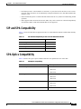
SIP and SPA Compatibility
Table 1-1 shows the SIPs that are supported on the Cisco XR 12000 Series Router and the SPAs that they
support:
Table 1-1
SIP and SPA Compatibility on the Cisco XR 12000 Series Router
SPA
10G SIP
1-Port 10-Gigabit Ethernet SPA
Yes
5-Port Gigabit Ethernet SPA
Yes
10-Port Gigabit Ethernet SPA
Yes
1-Port OC-192c/STM-64 POS/RPR XFP SPA
Yes
SPA Optics Compatibility
Table 1-2 shows the types of optics modules that have been qualified for use with a SPA:
Table 1-2
SPA Optics Compatibility
SPA
Qualified Optics Modules
1-Port 10-Gigabit Ethernet SPA
5-Port Gigabit Ethernet SPA
10-Port Gigabit Ethernet SPA
1-Port OC-192c/STM-64 POS/RPR XFP SPA
•
SFP-GE-S
•
SFP-GE-L
•
SFP-GE-Z
•
SFP-GE-S
•
SFP-GE-L
•
SFP-GE-Z
•
SFP-GE-S
•
SFP-GE-L
•
SFP-GE-Z
•
XFP-10GLR-OC192SR
Cisco XR 12000 Series Router SIP and SPA Software Configuration Guide, Release 3.2
Release 3.2, OL-6396-01, Rev.A1 January 9, 2006
1-3
Chapter 1
SIP and SPA Product Overview
SPA Interface Addresses on Cisco XR 12000 Series Routers
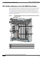
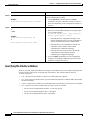
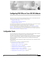
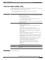
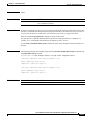
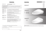
SPA Interface Addresses on Cisco XR 12000 Series Routers
A Cisco 12000 Series Router identifies a SPA interface address by its rack number, SIP slot number, SPA
subslot, and port number on the SPA, in the format rack/slot/subslot/port. The rack number is always 0
for the Cisco 12000 Series Router. Slots, subslots and ports are numbered starting from 0, so each
Cisco 12000 SIP-600 has two subslots 0 (left) and 1 (right). For example, the interface address of a
1-port SPA located in the second SIP subslot, where the SIP is inserted into router line card slot 3 is
0/3/2/0. Figure 1-3 shows the slot, subslot, and port locations for the 1-Port 10-Gigabit Ethernet SPA and
the 10-Port Gigabit Ethernet SPA.
Figure 1-3
Slot, Subslot, and Port Locations for the 1-Port 10-Gigabit Ethernet SPA and 10-Port
Gigabit Ethernet SPA
MBUS
CSC
SFC
A
ALARM A
FAIL
B
ALARM B
MIN
OR
MA
AL
JOR
ITIC
CR
A
B
0
ENABLE
1
0
1
2
3
4
AC
TIV
E/L
INK
0
2
0
R
E IE KT
TIV RR P
AC CA RX
R
E IE KT
TIV RR P
AC CA RX
CT
EJE
CT
EJE
1
1
T-1
SLO 0
TSLO
T-1
SLO 0
TSLO
R
E IE KT
TIV RR P
AC CA RX
SPA-1XTENGE-XFP-A
R
E IE KT
TIV RR P
AC CA RX
R
E IE KT
TIV RR P
AC CA RX
US
AT
ST
2
2
LIN
K
ETH 0
LIN
K
ETH 0
LIN
K
ETH 1
LIN
K
ETH 1
A
DAT
A
DAT
R
E IE KT
TIV RR P
AC CA RX
SIG
BITS 0
SIG
BITS 0
3
SIG
BITS 1
SIG
BITS 1
T
AC
T
AC
3
T
AC
T
AC
AUX
AUX
R
E IE KT
TIV RR P
AC CA RX
R
E IE KT
TIV RR P
AC CA RX
CONSOLE
CONSOLE
3
ETH 2
ETH 2
T
SE
RE
129009
PERFORMANCE ROUTE PROCESSOR 2
PERFORMANCE ROUTE PROCESSOR 2
OC-48/STM-16-SCPOS
Q OC-3/STM-POS
Q OC-3/STM-POS
T
SE
RE
R
E IE KT
TIV RR P
AC CA RX
A
DAT
A
DAT
1
1
Slot 3
2
Subslot 0, Port 0/3/0/0
3
Subslot 1, Ports 0/3/1/0 to 0/3/1/9
Cisco XR 12000 Series Router SIP and SPA Software Configuration Guide, Release 3.2
1-4
Release 3.2, OL-6396-01, Rev.A1 January 9, 2006
Chapter 1
SIP and SPA Product Overview
SIP Software and Hardware Compatibility
SIP Software and Hardware Compatibility
For software configuration information, refer to the Cisco IOS XR software configuration and command
reference publications for the installed Cisco IOS XR release. Also refer to the Cisco IOS XR software
release notes for additional information. Table 1-3 lists the Cisco IOS XR releases that are compatible
with supported SIPs.
To ensure compatibility with the software, your SIPs should have a specific hardware revision number.
The number is printed on a label affixed to the component side of the card. The hardware revision
number can be displayed by using the show diags slot-number command. Table 1-3 lists the hardware
revision number for all supported SIPs.
Table 1-3
SIP Hardware and Software Compatibility
SIP
Part Number
Cisco 12000 SIP-600 12000-SIP-600
Minimum Cisco IOS Software
Release
Minimum Hardware
Revision
Release 3.2
1.0
The show version and show platform commands display the current hardware configuration of the
router, including the system software version that is currently loaded and running. For complete
descriptions of show commands, refer to the Cisco CRS-1 Series Carrier Routing System Getting Started
Guide and the Hardware Redundancy and Node Administration Commands on Cisco IOS XR Software
for the installed Cisco IOS XR release.
For instructions on getting started with Cisco IOS XR please refer to the Cisco IOS XR Getting Started
Guide for the installed Cisco IOS XR release.
Cisco XR 12000 Series Router SIP and SPA Software Configuration Guide, Release 3.2
Release 3.2, OL-6396-01, Rev.A1 January 9, 2006
1-5
Chapter 1
SIP and SPA Product Overview
SIP Software and Hardware Compatibility
Cisco XR 12000 Series Router SIP and SPA Software Configuration Guide, Release 3.2
1-6
Release 3.2, OL-6396-01, Rev.A1 January 9, 2006
C H A P T E R
2
Overview of the Cisco XR 12000 Series Router
SIPs
This chapter provides an overview of the release history, and feature and Management Information Base
(MIB) support for the SPA interface processors (SIPs) supported on the Cisco XR 12000 Series Routers.
This chapter includes the following sections:
•
Release History, page 2-1
•
Cisco 12000 SIP-600 Features, page 2-1
•
Supported MIBs, page 2-3
•
Displaying the SPA Hardware Type, page 2-6
Release History
Table 2-1 describes the release history for the SIP hardware.
Table 2-1
Release History for SIP Hardware
Release
Modification
Cisco IOS-XR Release 3.2
Support for the following SIP hardware was introduced on the
Cisco XR 12000 Series Routers:
•
Cisco 12000 SIP-600
Cisco 12000 SIP-600 Features
The Cisco 12000 SIP-600 provides a common 10 Gbps forwarding and queuing engine responsible for
packet classification, forwarding, queuing, and accounting without compromising performance. The
Cisco 12000 SIP-600 has two forwarding engines, one for ingress and one for egress. This allows the
user to implement different features and QoS policies for the ingress and egress interfaces. The multicast
replication is done by the egress forwarding engine, hence a very scalable multicast with built-in QoS.
The Modular Physical Layer Interface Module (PLIM) front end hosts up to 2 SPAs. Each SPA has a
dedicated 10 Gbps interface to the SPA controller. The SPA controller uses a fair bandwidth allocation
algorithm to share available and excess bandwidth between the 2 SPAs. The oversubscribed SPA does
not cause any packet-drop on the nonoversubscribed SPA, and any unused bandwidth from one SPA is
used by the other SPA.
Cisco XR 12000 Series Router SIP and SPA Software Configuration Guide, Release 3.2
Release 3.2, OL-6396-01, Rev.A1 January 9, 2006
2-1
Chapter 2
Overview of the Cisco XR 12000 Series Router SIPs
Cisco 12000 SIP-600 Features
The Cisco 12000 SIP-600 supports any combination of the following pluggable SPAs and Layer 2
encapsulations:
•
Concatenated OC-192 and OC-48
•
Gigabit Ethernet and 10 Gigabit Ethernet Interfaces
•
Point to Point Protocol (PPP)
•
High Level Data Link Control (HDLC)
•
Frame Relay
•
Dynamic Packet Transport (DPT)
•
Resilient Packet Ring (RPR)
•
802.17
•
VLANs
The SPA controller adapts the user traffic flowing between the SPA interfaces for the Layer 3 forwarding
engine. The SPA controller has two levels of priority queuing with Deficit Round Robin (DRR) and
Strict Priority Servicing. Strict Priority Servicing protects higher-priority packets by dropping lower
priority packets first, in an oversubscribed configuration (persistent incoming traffic rate of 20 Gbps.)
The Cisco 12000 SIP-600 provides the following key features:
•
Dynamic allocation of 4096 input-shaped queues to any interface, subinterface, Frame Relay
connection, VLAN.
•
Ingress Queuing:
– 2048 unicast Modified DRR (MDRR) queues
– 16 high priority queues
– 8 multicast queues
– 2 fabric priority queues
•
Egress Queuing:
– 8192 Modified DRR (MDRR) queues dynamically shared across 4096 interfaces;
– Hierarchical shaping (interface, queue)
•
High number of IPv4, IPv6, Multiprotocol Label Switching (MPLS), and MPLS VKPN unicast and
multicast routes: Up to 1M IPv4/MPLS routes and up to 512,000 IPv6 prefixes.
•
Per-VLAN/source-destination MAC address filtering, trunking, accounting, QoS, match VLAN
QoS, Hot Standby Router Protocol (HSRP)/Virtual Router Redundancy Protocol (VRRP)
hierarchical rate limiting and policing, dynamic queuing, and traffic shaping.
•
Input and output full NetFlow Version 8 in hardware.
•
Input and output Sampled NetFlow, Versions 5, 8, and 9 in hardware.
•
Building Integrated Timing Supply (BITS)
•
Online Insertion Removal (OIR) of SPAs; OIR of one SPA does not effect the traffic on other SPA
interfaces.
•
Multi-router Automatic Protection Switching (MR-APS)
•
Layer 2 VPNs over MPLS (Any transport over MPLS (AToM)) and Over IP Layer 2 Tunneling
Protocol Version 3 (L2TPv3)
Cisco XR 12000 Series Router SIP and SPA Software Configuration Guide, Release 3.2
2-2
Release 3.2, OL-6396-01, Rev.A1 January 9, 2006
Chapter 2
Overview of the Cisco XR 12000 Series Router SIPs
Supported MIBs
Supported MIBs
The following MIBs are supported in Cisco IOS-XR Release 3.2 for the Cisco 12000 SIP-600 on a Cisco
XR 12000 Series Router:
•
IPv6 MIB
•
ICMPv6 MIB
•
IPv6 TCP MIB
•
IPv6 UDP MIB
•
SNMP v1, v2c, v3 (RFC 1157, 1901-07)
•
MIB II, including interface extensions (RFC 1213, 2011-13, 2233)
•
Cisco GSR Manager
•
CiscoView
•
ifIndex persistence
•
64-bit counters
•
APS Extensions MIB
•
ATM CON MIB
•
ATM Forum Address MIB
•
ATM Forum MIB
•
ATM MIB
•
BGP-4 MIB
•
CAR MIB
•
Cisco AAL5 MIB
•
Cisco APS MIB
•
Cisco ATM Extensions MIB
•
Cisco BGP Policy Accounting MIB
•
Cisco Bulk File MIB
•
Cisco CAR MIB
•
Cisco CDP MIB
•
Cisco Class-Based QoS MIB (aka MQC MIB)
•
Cisco Config Copy MIB
•
Cisco Config Man MIB
•
Cisco Enhanced MemPool MIB
•
Cisco EnvMon MIB
•
Cisco Flash MIB
•
Cisco Frame Relay MIB
•
Cisco FRU MIB
•
Cisco FTP Client MIB
•
Cisco HSRP Extensions MIB
Cisco XR 12000 Series Router SIP and SPA Software Configuration Guide, Release 3.2
Release 3.2, OL-6396-01, Rev.A1 January 9, 2006
2-3
Chapter 2
Overview of the Cisco XR 12000 Series Router SIPs
Supported MIBs
•
Cisco HSRP MIB
•
Cisco IETF ATM2 PVCTRAP MIB
•
Cisco Image MIB
•
Cisco IP Statistics MIB
•
Cisco IP Mroute MIB
•
Cisco MDRR MIB
•
Cisco Memory Pool MIN
•
Cisco Optical Monitoring MIB
•
Cisco PIM MIB
•
Cisco Ping MIB
•
Cisco Process MIB
•
Cisco Queue MIB
•
Cisco RTT Monitor MIB (SAA)
•
Cisco SRP MIB
•
Cisco Syslog MIB
•
Cisco TCP MIB
•
Cisco VLAN IFTABLE Relationship MIB
•
Cisco WRED MIB
•
DPT MIB
•
DS1/E1 MIB
•
DS3/E3 MIB
•
Entity MIB
•
Entity II MIB
•
Ethernet MIB
•
Ethernet RMON MIB
•
Ether-like MIB
•
Event MIB
•
Expression MIB
•
Fabric MIB
•
Frame Relay MIB (IETF)
•
Frame Relay DTE MIB
•
HSRP MIB
•
IF MIB
•
IF MIB for VLANs
•
IGMP MIB
•
Interfaces MIB
•
Int-Serv MIB
•
Int-Serv Guaranteed MIB
Cisco XR 12000 Series Router SIP and SPA Software Configuration Guide, Release 3.2
2-4
Release 3.2, OL-6396-01, Rev.A1 January 9, 2006
Chapter 2
Overview of the Cisco XR 12000 Series Router SIPs
Supported MIBs
•
IP Mroute MIB
•
MPLS MIB
•
MPLS LDP MIB
•
MPLS LSR MIB
•
MPLS-TE MIB
•
MPLS-TE Topo MIB
•
MPLS-VPN MIB
•
MPLS-DE-TE MIB
•
MQC MIB
•
MSDP MIB
•
Old Cisco Chassis MIB
•
Old Cisco CPU MIB
•
Old Cisco Interfaces MIB
•
Old Cisco IP MIB
•
Old Cisco Memory MIB
•
Old Cisco System MIB
•
Old Cisco TCP MIB
•
Old Cisco TS MIB
•
OSPFv2 MIB
•
PIM MIB
•
PSA Microcode MIB
•
RFC1213 MIB
•
RFC1253 MIB
•
RFC1315 MIB
•
RFC1406 MIB
•
RFC1407 MIB
•
RFC1398 MIB
•
RFC1595 MIB
•
RMON MIB
•
RS232C MIB
•
RSVP MIB
•
SNMP Framework MIB
•
SNMP Target MIB
•
SNMP USM MIB
•
SNMP VACM MIB
•
SNMPv2 MIB
•
SNMP v3 MIB
•
SONET/SDH MIB
Cisco XR 12000 Series Router SIP and SPA Software Configuration Guide, Release 3.2
Release 3.2, OL-6396-01, Rev.A1 January 9, 2006
2-5
Chapter 2
Overview of the Cisco XR 12000 Series Router SIPs
Displaying the SPA Hardware Type
•
SONET Traps
•
Syslog Trap Alert on DLCI loss
•
TCP MIB
•
UDP MIB
•
WRED MIB
To locate and download MIBs for selected platforms, Cisco IOS-XR releases, and feature sets, use Cisco
MIB Locator found at the following URL:
http://www.cisco.com/go/mibs
If Cisco MIB Locator does not support the MIB information that you need, you can also obtain a list of
supported MIBs and download MIBs from the Cisco MIBs page at the following URL:
http://www.cisco.com/public/sw-center/netmgmt/cmtk/mibs.shtml
To access Cisco MIB Locator, you must have an account on Cisco.com. If you have forgotten or lost your
account information, send a blank e-mail to [email protected]. An automatic check will verify
that your e-mail address is registered with Cisco.com. If the check is successful, account details with a
new random password will be e-mailed to you. Qualified users can establish an account on Cisco.com
by following the directions found at this URL:
http://www.cisco.com/register
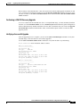
Displaying the SPA Hardware Type
To verify the SPA hardware type that is installed in your Cisco XR 12000 Series Router, you can use the
show inventory command.
Table 2-2 shows the hardware description that appears in the show command output for each type of SPA
that is supported on the Cisco XR 12000 Series Router.
Table 2-2
SPA Hardware Descriptions in show Commands
SPA
Description in show inventory Command
1-Port 10-Gigabit Ethernet SPA
SPA-1XTENGE-XFP
5-Port Gigabit Ethernet SPA
SPA-5XTENGE-XFP
10-Port Gigabit Ethernet SPA
SPA-10XGE-XFP
1-Port OC-192c/STM-64 POS/RPR XFP SPA
SPA-OC192POS
Cisco XR 12000 Series Router SIP and SPA Software Configuration Guide, Release 3.2
2-6
Release 3.2, OL-6396-01, Rev.A1 January 9, 2006
Chapter 2
Overview of the Cisco XR 12000 Series Router SIPs
Displaying the SPA Hardware Type
Example of the show inventory Command
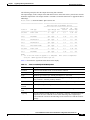
The following example shows output from the show inventory command on a Cisco XR 12000 Series
Router with a Cisco 12000 SIP-600 installed in slot 3:
RP/0/0/CPU0:x-21# show inventory
NAME: "0/0/CPU0", DESCR: "Cisco 12000 Series Performance Route Processor 2"
PID: PRP-2
, VID: N/A, SN: SAD0826025M
NAME: "0/3/CPU0", DESCR: "Cisco 12000 Series SPA Interface Processor-600 "
PID: 12000-SIP-600
, VID: N/A, SN: SAD073303F8
NAME: "0/3/0", DESCR: "1-Port OC192/STM64 POS/RPR XFP Optics"
PID: SPA-OC192POS-XFP , VID: V01, SN: PRTA1204185
NAME: "0/3/1", DESCR: "1-port 10GbE Shared Port Adapter XFP based"
PID: SPA-1XTENGE-XFP
, VID: V01, SN: PRTA2104133
Cisco XR 12000 Series Router SIP and SPA Software Configuration Guide, Release 3.2
Release 3.2, OL-6396-01, Rev.A1 January 9, 2006
2-7
Chapter 2
Overview of the Cisco XR 12000 Series Router SIPs
Displaying the SPA Hardware Type
Cisco XR 12000 Series Router SIP and SPA Software Configuration Guide, Release 3.2
2-8
Release 3.2, OL-6396-01, Rev.A1 January 9, 2006
PA R T
1
Gigabit Ethernet Shared Port Adapters
C H A P T E R
3
Overview of the Gigabit Ethernet SPAs
This chapter provides an overview of the release history, and feature and Management Information Base
(MIB) support for the Gigabit Ethernet SPAs on the Cisco XR 12000 Series Router.
This chapter includes the following sections:
•
Release History, page 3-1
•
Supported Features, page 3-2
•
Supported MIBs, page 3-2
•
SPA Architecture, page 3-3
•
Displaying the SPA Hardware Type, page 3-4
Release History
Table 3-1 provides the release and modification history for Ethernet SPA-related features and
enhancements on the Cisco XR 12000 Series Router.
Table 3-1
Release History for Ethernet SPA
Release
Modification
Cisco IOS-XR Release 3.2 Support for the following SPAs was introduced on Cisco XR 12000
Series Routers:
•
1-Port 10-Gigabit Ethernet SPA
•
5-Port Gigabit Ethernet SPA
•
10-Port Gigabit Ethernet SPA
Cisco XR 12000 Series Router SIP and SPA Software Configuration Guide, Release 3.2
Release 3.2, OL-6396-01, Rev.A1 January 9, 2006
3-1
Chapter 3
Overview of the Gigabit Ethernet SPAs
Supported Features
Supported Features
This section provides a list of some of the primary features supported with the Gigabit Ethernet.
Gigabit Ethernet SPA Features
The following is a list of some of the significant hardware and software features supported by the Gigabit
Ethernet SPAs on the Cisco XR 12000 Series Routers:
•
Auto negotiation
•
Full-duplex operation
•
802.1Q VLAN termination
•
Jumbo frames support (9188 bytes)
•
Support for command-line interface (CLI) controlled OIR
•
802.3x flow control
•
Up to 4K VLAN per SPA
•
Up to 5K Mac Accounting Entries per SPA (Source Mac Accounting on the ingress and Destination
Mac Accounting on the egress)
•
Up to 2K MAC address entries for destination MAC address filtering per SPA, and up to 1K MAC
address filtering entries per port
•
Per port byte and packet counters for policy drops, oversubscription drops, CRC error drops, packet
sizes, Unicast, multicast, and broadcast packets
•
Per VLAN byte and packet counters for policy drops, oversubscription drops, Unicast, multicast,
and broadcast packets
•
Per-port byte counters for good bytes and dropped bytes
•
Ethernet over Multi-protocol Label Switching (EoMPLS)
•
Quality of service (QoS)
•
Hot Standby Router Protocol (HSRP)
•
Virtual Router Redundancy Protocol (VRRP)
Supported MIBs
The following MIBs are supported by the Gigabit Ethernet SPAs on the Cisco XR 12000 Series Routers:
•
Entity-MIB (RFC 2737)
•
Cisco-entity-asset-MIB
•
Cisco-entity-field-replaceable unit (FRU)-control-MIB
•
Cisco-entity-alarm-MIB
•
Cisco-entity-sensor-MIB
•
IF-MIB
•
Etherlike-MIB (RFC 2665)
Cisco XR 12000 Series Router SIP and SPA Software Configuration Guide, Release 3.2
3-2
Release 3.2, OL-6396-01, Rev.A1 January 9, 2006
Chapter 3
Overview of the Gigabit Ethernet SPAs
SPA Architecture
•
Remote Monitoring (RMON)-MIB (RFC 1757)
•
Cisco-class-based-QoS-MIB
•
MPLS-related MIBs
•
Ethernet MIB/RMON
To locate and download MIBs for selected platforms, Cisco IOS releases, and feature sets, use
Cisco MIB Locator found at the following URL:
http://tools.cisco.com/ITDIT/MIBS/servlet/index
If Cisco MIB Locator does not support the MIB information that you need, you can also obtain a list of
supported MIBs and download MIBs from the Cisco MIBs page at the following URL:
http://www.cisco.com/public/sw-center/netmgmt/cmtk/mibs.shtml
To access Cisco MIB Locator, you must have an account on Cisco.com. If you have forgotten or lost your
account information, send a blank e-mail to [email protected]. An automatic check will verify
that your e-mail address is registered with Cisco.com. If the check is successful, account details with a
new random password will be e-mailed to you. Qualified users can establish an account on Cisco.com
by following the directions found at this URL:
http://www.cisco.com/register
SPA Architecture
This section provides an overview of the architecture of the Gigabit Ethernet SPAs and describes the path
of a packet in the ingress and egress directions. Some of these areas of the architecture are referenced in
the SPA software and can be helpful to understand when troubleshooting or interpreting some of the SPA
CLI and show command output.
Every incoming and outgoing packet on the Gigabit Ethernet SPAs goes through the physical (PHY) SFP
optics, Media Access Control (MAC), and ASIC devices.
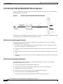
Path of a Packet in the Ingress Direction
The following steps describe the path of an ingress packet through the Gigabit Ethernet SPAs:
1.
The PHY SFP optics device receives incoming frames on a per-port basis from one of the laser optic
interface connectors.
2.
The PHY laser optics device processes the frame and sends it over the XAUI path to the MAC
device.
3.
The MAC device receives the frame, strips the CRCs, and sends the packet via the SPI 4.2 bus to the
ASIC.
4.
The ASIC takes the packet from the MAC devices and classifies the ethernet information. CAM
lookups based on etype, port, VLAN, and source and destination address information determine
whether the packet is dropped or forwarded to the SPA interface. If the packet is forwarded to the
SPA interface, an 8-byte SHIM header that is used for additional downstream packet processing is
propounded to the packet.
Cisco XR 12000 Series Router SIP and SPA Software Configuration Guide, Release 3.2
Release 3.2, OL-6396-01, Rev.A1 January 9, 2006
3-3
Chapter 3
Overview of the Gigabit Ethernet SPAs
Displaying the SPA Hardware Type
Path of a Packet in the Egress Direction
The following steps describe the path of an egress packet from the SIP through the Gigabit Ethernet SPA:
1.
The packet is sent to the ASIC using the SPI 4.2 Bus. The packets are received with layer 2 and layer
3 headers in addition to the packet data.
2.
The ASIC uses port number, destination MAC address, destination address type, and VLAN ID to
perform parallel CAM lookups. If the packet is forwarded, it is forwarded via the SPI 4.2 Bus to the
MAC device.
The MAC device forwards the packets to the PHY laser optic interface, which transmits the packet.
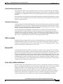
Displaying the SPA Hardware Type
To verify the SPA hardware type that is installed in your Cisco XR 12000 Series Router, you can use the
show interfaces command. For more information about these commands, see Chapter 10, “Command
Reference.”
To verify the SPA hardware type that is installed in your Cisco XR 12000 Series Router, use the
following commands:
•
show inventory
•
show hw-module subslot brief
Table 3-2 shows the hardware description that appears in the show command output for each type of
Gigabit Ethernet SPA that is supported on Cisco XR 12000 Series Routers.
Table 3-2
SPA Hardware Descriptions in show Commands
SPA
Description in show commands
1-Port 10-Gigabit Ethernet SPA
Hardware is GigMac 1 Port 10 GigabitEthernet
5-Port Gigabit Ethernet SPA
Hardware is FiveGigE
10-Port Gigabit Ethernet SPA
Hardware is TenGigE
Example of the show inventory Command
The following example shows output from the show inventory command on a Cisco XR 12000 Series
Router with an 1-Port 10-Gigabit Ethernet SPA installed in subslot 1 of the SIP in slot 3:
RP/0/0/CPU0:x-21#show inventory
NAME: "0/0/CPU0", DESCR: "Cisco 12000 Series Performance Route Processor 2"
PID: PRP-2 , VID: N/A, SN: SAD0826025M
NAME: "0/3/CPU0", DESCR: "Cisco 12000 Series SPA Interface Processor-600 "
PID: 12000-SIP-600 , VID: N/A, SN: SAD073303F8
NAME: "0/3/0", DESCR: "1-Port OC192/STM64 POS/RPR XFP Optics"
PID: SPA-OC192POS-XFP , VID: V01, SN: PRTA1204185
NAME: "0/3/1", DESCR: "1-port 10GbE Shared Port Adapter XFP based"
PID: SPA-1XTENGE-XFP , VID: V01, SN: PRTA2104133
Cisco XR 12000 Series Router SIP and SPA Software Configuration Guide, Release 3.2
3-4
Release 3.2, OL-6396-01, Rev.A1 January 9, 2006
Chapter 3
Overview of the Gigabit Ethernet SPAs
Displaying the SPA Hardware Type
Table 3-3 describes the significant fields shown in the display.
Table 3-3
show inventory Field Descriptions
Field
Description
NAME
Identifies the hardware for which the inventory information is displayed. If you are
displaying raw inventory, this field shows the node name. For a node, the NAME is
expressed in rack/slot/subslot notation.
DESCR
Node description. The description “1-port 10GbE Shared Port Adapter XFP base”
indicates the 1-Port 10-Gigabit Ethernet SPA.
PID
Physical model name of the node.
VID
Physical hardware revision of the node.
SN
Physical serial number for the node.
Example of the show hw-module subslot Command
The following example shows output from the show hw-module subslot brief command on a Cisco XR
12000 Series Router with an 1-Port 10-Gigabit Ethernet SPA installed in subslot 1 of the Cisco 12000
SIP-600 in slot 3:
RP/0/0/CPU0:x-21#show hw-module subslot 0/3/cpu0 brief
Subslot 0/3/0 brief info:
----------------------SPA inserted: YES
SPA type: 1xOC192 POS/RPR HHSPA with XFP
SPA operational state: READY
SPA cfg admin up: YES
Subslot 0/3/1 brief info:
----------------------SPA inserted: YES
SPA type: 1x10GE XFP SPA
SPA operational state: READY
SPA cfg admin up: YES
Use the format show hw-module subslot 0/3/cpu0 brief to display information regarding all SPAs
installed in the card in slot 3.
Table 3-4 describes the significant fields shown in the display.
Table 3-4
show hw-module subslot brief Field Descriptions
Field
Description
SPA inserted
Indicates if a SPA is currently detected in the subslot.
SPA type
Description of SPA including the technology type, number of
ports, height of SPA (HHSPA—single height,
FHSPA—double height), and optics type.
SPA operational state
Current state of the SPA module.
SPA cfg admin up
Configured state of the SPA: YES—the SPA is not shut down,
NO—the SPA is shut down.
Cisco XR 12000 Series Router SIP and SPA Software Configuration Guide, Release 3.2
Release 3.2, OL-6396-01, Rev.A1 January 9, 2006
3-5
Chapter 3
Overview of the Gigabit Ethernet SPAs
Displaying the SPA Hardware Type
Cisco XR 12000 Series Router SIP and SPA Software Configuration Guide, Release 3.2
3-6
Release 3.2, OL-6396-01, Rev.A1 January 9, 2006
C H A P T E R
4
Configuring Ethernet SPAs on Cisco IOS XR
Software
This chapter provides information about configuring Ethernet SPAs on the Cisco XR 12000 Series
Router running Cisco IOS XR software. It includes the following sections:
•
Configuration Tasks, page 4-1
•
Verifying the Interface Configuration, page 4-9
•
Configuration Examples, page 4-10
For information about managing your system images and configuration files, refer to the Cisco IOS XR
Getting Started Guide, Release 3.2 and the Cisco IOS XR Commands Master List, Release 3.2
publications.
For more information about the commands used in this chapter, see Chapter 10, “Command Reference”
which documents new and modified commands and the Cisco IOS XR Interface and Hardware
Component Command Reference, Release 3.0. For more information about accessing these publications,
see the “Related Documentation” section in the “Preface”.
Configuration Tasks
This section describes how to configure the Gigabit Ethernet SPAs. It includes the following topics:
•
Required Configuration Steps, page 4-1
•
Specifying the Interface Address, page 4-4
•
Configuring a Basic Ethernet Interface, page 4-5
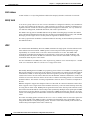
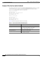
Required Configuration Steps
This section lists the required configuration steps to configure the Gigabit Ethernet SPAs. Some of the
required configuration commands have default values that might be appropriate for your network. If the
default value is correct for your network, then you do not need to configure the command. These
commands are indicated by “(Optional)” in the purpose column.
Note
See the “Configuring a Basic Ethernet Interface” section on page 4-5 for detailed information regarding
the parameters that can be configured.
Cisco XR 12000 Series Router SIP and SPA Software Configuration Guide, Release 3.2
Release 3.2, OL-6396-01, Rev.A1 January 9, 2006
4-1
Chapter 4
Configuring Ethernet SPAs on Cisco IOS XR Software
Configuration Tasks
SUMMARY STEPS
1.
show version
2.
show interface
3.
configure
4.
interface type number
5.
ipv4 address ip-address mask
or
ipv6 address ipv6-prefix/prefix-length
6.
flow-control {bidirectional | egress | ingress}
7.
negotiation auto
8.
mac-accounting {egress | ingress}
9.
mtu value
10. mac-address value1.value2.value3
11. no shutdown
12. end
or
commit
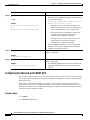
DETAILED STEPS
Step 1
Command or Action
Purpose
show version
(Optional) Displays the current software version, and can
also be used to confirm that the router recognizes the line
card.
Example:
RP/0/0/CPU0:Router> show version
Step 2
show interfaces
(Optional) Displays the configured interface and checks the
status of each interface port.
Example:
RP/0/0/CPU0:Router> show interface
Step 3
configure
Enters global configuration mode.
Example:
RP/0/0/CPU0:Router> configure terminal
Step 4
interface type number
Enters interface configuration mode, where:
•
type—Specifies gigabitethernet for the Gigabit
Ethernet SPAs.
•
number—Specifies the Ethernet interface in the
notation rack/slot/module/port.
Example:
RP/0/0/CPU0:Router(config)# interface
gigabitethernet 0/2/0/1
The example indicates Gigabit Ethernet interface 1, on a
SPA in subslot 0, in line card slot 2.
Cisco XR 12000 Series Router SIP and SPA Software Configuration Guide, Release 3.2
4-2
Release 3.2, OL-6396-01, Rev.A1 January 9, 2006
Chapter 4
Configuring Ethernet SPAs on Cisco IOS XR Software
Configuration Tasks
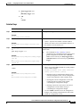
Step 5
Command or Action
Purpose
ipv4 address ip-address mask
Assigns an IP address to the interface, where:
or
•
ip-address mask—Specifies an IPv4 IP address and
subnet mask.
•
ipv6-prefix/prefix-length—Specifies an IPv6 network
address and prefix length.
ipv6 address ipv6-prefix/prefix-length
Example:
RP/0/0/CPU0:Router(config-if)# ipv4 address
172.18.189.38 255.255.255.224
or
RP/0/0/CPU0:Router(config-if)# ipv6 address
3000:1116::1:3:300:1/112
Step 6
flow-control {bidirectional | egress | ingress}
(Optional) Enables the sending of flow control pause
frames.
Example:
RP/0/0/CPU0:Router(config-if)# flow control
ingress
Step 7
(Optional) Enables autonegotiation of the interface with the
connected interface.
negotiation auto
Example:
RP/0/0/CPU0:Router(config-if)# negotiation auto
Step 8
mac-accounting {egress | ingress}
Example:
RP/0/0/CPU0:Router(config-if)# mac-accounting
egress
Step 9
(Optional) Generates accounting information for IP traffic
based on the source and destination MAC addresses on
LAN interfaces.
•
To disable MAC accounting, use the no form of this
command.
(Optional) Sets the MTU value for the interface.
mtu value
•
Example:
The default is 1514 for normal frames and 1518 for
802.1Q tagged frames.
RP/0/0/CPU0:Router(config-if# mtu 1448
Step 10
mac-address value1.value2.value3
(Optional) Sets the MAC layer address of the management
Ethernet interface.
•
Example:
RP/0/0/CPU0:Router(config-if)# mac address
0001.2468.ABCD
The values are the high, middle, and low 2 bytes,
respectively, of the MAC address in hexadecimal. The
range of each 2-byte value is 0 to ffff.
Cisco XR 12000 Series Router SIP and SPA Software Configuration Guide, Release 3.2
Release 3.2, OL-6396-01, Rev.A1 January 9, 2006
4-3
Chapter 4
Configuring Ethernet SPAs on Cisco IOS XR Software
Configuration Tasks
Step 11
Command or Action
Purpose
no shutdown
Removes the shutdown configuration, which forces an
interface administratively down.
•
Example:
RP/0/0/CPU0:Router(config-if)# no shutdown
Step 12
The no shutdown command passes an enable
command to the SPA, which then returns to an up or a
down state depending on the configuration and state of
the link.
Saves configuration changes.
end
or
•
commit
When you issue the end command, the system prompts
you to commit changes:
Uncommitted changes found. Commit them before
exiting (yes/no/cancel)? [cancel]:
Example:
RP/0/0/CPU0:Router(config-if)# end
– Entering yes saves configuration changes to the
or
running configuration file, exits the configuration
session, and returns the router to EXEC mode.
RP/0/0/CPU0:Router(config-if)# commit
– Entering no exits the configuration session and
returns the router to EXEC mode without
committing the configuration changes.
– Entering cancel leaves the router in the current
configuration session without exiting or
committing the configuration changes.
•
Use the commit command to save the configuration
changes to the running configuration file and remain
within the configuration session.
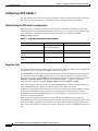
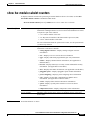
Specifying the Interface Address
SPAs on Cisco XR 12000 Series Routers running Cisco IOS XR software use an addressing format that
specifies the physical location of the SIP, SPA, and interface. The interface address format is
rack/slot/subslot/port:
•
rack—Specifies the rack number, 0 for the Cisco XR 12000 Series Router.
•
slot—Specifies the slot number in the Cisco XR 12000 Series Router in which the MSC that contains
the SPA is installed.
•
subslot—Specifies the secondary slot on the MSC where the SPA that you want to select is installed.
•
port—Specifies the interface number that you want to select on the SPA:
– For the 1-Port 10-Gigabit Ethernet SPA—0 is the only option.
– For the 10-Port Gigabit Ethernet SPA—0 through 9
– For the 5-Port Gigabit Ethernet SPA—0 through 4
Cisco XR 12000 Series Router SIP and SPA Software Configuration Guide, Release 3.2
4-4
Release 3.2, OL-6396-01, Rev.A1 January 9, 2006
Chapter 4
Configuring Ethernet SPAs on Cisco IOS XR Software
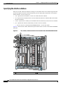
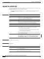
Configuration Tasks
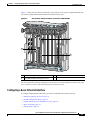
Figure 4-1 shows the slot, subslot, and interface port locations of the 1-Port 10-Gigabit Ethernet SPA
and 10-Port Gigabit Ethernet SPA installed in the SIP located in slot 3.
Figure 4-1
Slot, Subslot, and Port Locations on the Cisco 12000 SIP-600
MBUS
CSC
SFC
A
ALARM A
FAIL
B
ALARM B
MIN
OR
MA
AL
JOR
ITIC
CR
A
B
0
ENABLE
1
0
1
2
3
4
AC
TIV
E/L
INK
0
2
0
R
E IE KT
TIV RR P
AC CA RX
R
E IE KT
TIV RR P
AC CA RX
CT
EJE
CT
EJE
1
1
T-1
SLO 0
TSLO
T-1
SLO 0
TSLO
R
E IE KT
TIV RR P
AC CA RX
SPA-1XTENGE-XFP-A
R
E IE KT
TIV RR P
AC CA RX
R
E IE KT
TIV RR P
AC CA RX
US
AT
ST
2
2
LIN
K
K
ETH 0
LIN
ETH 0
LIN
K
K
ETH 1
LIN
ETH 1
A
DAT
A
DAT
R
E IE KT
TIV RR P
AC CA RX
SIG
BITS 0
SIG
BITS 0
3
SIG
BITS 1
SIG
BITS 1
T
AC
T
AC
3
T
AC
T
AC
AUX
AUX
R
E IE KT
TIV RR P
AC CA RX
R
E IE KT
TIV RR P
AC CA RX
CONSOLE
CONSOLE
3
ETH 2
ETH 2
T
SE
RE
129009
PERFORMANCE ROUTE PROCESSOR 2
PERFORMANCE ROUTE PROCESSOR 2
OC-48/STM-16-SCPOS
Q OC-3/STM-POS
Q OC-3/STM-POS
T
SE
RE
R
E IE KT
TIV RR P
AC CA RX
A
DAT
A
DAT
1
1
Router slot number 3
2
SPA subslot number 0 with port 0/3/0/0
3
SPA subslot 1 with ports 0/3/1/0 to 0/3/1/9
For more information about the installation of cards on the Cisco XR 12000 Series Router, refer to the
Cisco 12000 Series Router SIP and SPA Hardware Installation Guide.
Configuring a Basic Ethernet Interface
To configure Gigabit Ethernet interfaces you need to understand the following concepts:
•
Ethernet Technology Overview, page 4-6
•
Default Configuration Values, page 4-6
•
Gigabit Ethernet Protocol Standards Overview, page 4-6
•
MAC Accounting, page 4-7
•
Ethernet MTU, page 4-7
Cisco XR 12000 Series Router SIP and SPA Software Configuration Guide, Release 3.2
Release 3.2, OL-6396-01, Rev.A1 January 9, 2006
4-5
Chapter 4
Configuring Ethernet SPAs on Cisco IOS XR Software
Configuration Tasks
•
Flow Control on Ethernet Interfaces, page 4-7
•
MAC Address, page 4-8
•
802.1Q VLAN, page 4-8
•
VRRP, page 4-8
•
HSRP, page 4-8
Ethernet Technology Overview
Ethernet was developed in the mid-1970s as a 10-Mbps networking protocol operating over a heavy coax
cable.
Today, although many networks have migrated to Fast Ethernet (100 Mbps), Gigabit Ethernet
(1000 Mbps), and 10-Gigabit Ethernet (10 Gbps), 10-Mbps Ethernet is still in widespread use and forms
the basis of most networks.
Ethernet is defined by the IEEE 802.3 international standard. It enables the connection of up to 1024
nodes over coax, twisted-pair, or fiber-optic cable.
Default Configuration Values
When an interface is enabled on an Ethernet SPA and associated SIP, the following default interface
configuration parameters are present. See Table 4-1.
Note
You must specifically configure the shutdown command to bring an interface administratively down.
The interface default is no shutdown. When a SPA and SIP are first inserted into the router, if there is
no established preconfiguration for it, the configuration manager adds a shutdown item to its
configuration. This shutdown can be removed only by entering the no shutdown command.
Table 4-1
Ethernet SPA Default Configuration Values
Parameter
Configuration File Entry
Default Value
MAC Accounting
mac-accounting
off
Flow Control
off
MTU
mtu
1514 for normal interfaces, 1518 for 802.1Q
VLAN
MAC Address
mac address
Hardware burned in address (BIA)
Gigabit Ethernet Protocol Standards Overview
IEEE 802.3ab 1000BASE-T Gigabit Ethernet
The IEEE 802.3ab protocol standards, or Gigabit Ethernet over copper (also known as 1000BaseT) is an
extension of the existing Fast Ethernet standard. It specifies Gigabit Ethernet operation over the
Category 5e/6 cabling systems already installed, making it a highly cost-effective solution. As a result,
most copper-based environments that run Fast Ethernet can also run Gigabit Ethernet over the existing
network infrastructure in order to dramatically boost network performance for demanding applications.
Cisco XR 12000 Series Router SIP and SPA Software Configuration Guide, Release 3.2
4-6
Release 3.2, OL-6396-01, Rev.A1 January 9, 2006
Chapter 4
Configuring Ethernet SPAs on Cisco IOS XR Software
Configuration Tasks
IEEE 802.3z 1000 Mbps Gigabit Ethernet
Gigabit Ethernet builds on top of the Ethernet protocol, but increases speed tenfold over Fast Ethernet
to 1000 Mbps, or 1 Gbps. Gigabit Ethernet allows Ethernet to scale from 10 or 100 Mbps at the desktop
to 100 Mbps up to 1000 Mbps in the data center. Gigabit Ethernet conforms to the IEEE 802.3z protocol
standard.
By leveraging the current Ethernet standard and the installed base of Ethernet and Fast Ethernet switches
and routers, network managers do not need to retrain and relearn a new technology in order to provide
support for Gigabit Ethernet.
IEEE 802.3ae 10 Gbps Ethernet
Under the International Standards Organization’s Open Systems Interconnection (OSI) model, Ethernet
is fundamentally a Layer 2 protocol. 10-Gigabit Ethernet uses the IEEE 802.3 Ethernet MAC protocol,
the IEEE 802.3 Ethernet frame format, and the minimum and maximum IEEE 802.3 frame size. 10 Gbps
Ethernet conforms to the IEEE 802.3ae protocol standards.
Just as 1000BASE-X and 1000BASE-T (Gigabit Ethernet) remained true to the Ethernet model,
10-Gigabit Ethernet continues the natural evolution of Ethernet in speed and distance. Because it is a
full-duplex only and fiber-only technology, it does not need the carrier-sensing multiple-access with
collision detection (CSMA/CD) protocol that defines slower, half-duplex Ethernet technologies. In every
other respect, 10-Gigabit Ethernet remains true to the original Ethernet model.
MAC Accounting
The MAC address accounting feature provides accounting information for IP traffic based on the source
and destination MAC addresses on LAN interfaces. This feature calculates the total packet and byte
counts for a LAN interface that receives or sends IP packets to or from a unique MAC address. It also
records a time stamp for the last packet received or sent.
Ethernet MTU
A maximum transmission unit (MTU) is the largest size packet or frame, specified in octets (eight-bit
bytes), that can be sent in a packet- or frame-based network such as the Internet. The Internet’s TCP uses
the MTU to determine the maximum size of each packet in any transmission. Too large an MTU size
may mean retransmissions if the packet encounters a router that can’t handle the large packet. Too small
an MTU size means relatively more header overhead and more acknowledgements that have to be sent
and handled. Most computer operating systems provide a default MTU value that is suitable for most
users. The default value is 1514 for standard frames and 1518 for 802.1Q tagged frames. These numbers
exclude the 4 byte frame check sequence (FCS).
Flow Control on Ethernet Interfaces
The flow control used on Gigabit Ethernet interfaces consists of periodically sending flow control pause
frames. It is fundamentally different from the usual full- and half-duplex flow control used on standard
management interfaces. Flow control can be activated for either ingress traffic, egress traffic or
bi-directional traffic. Flow control by default is not activated on SPA Gigabit Ethernet interfaces.
Some hardware has restrictions on how flow-control can be configured. If you attempt to configure a
method of flow-control that is not supported, an error is returned at configuration verification. The
current operational flow control settings can be displayed using the show interfaces command.
Cisco XR 12000 Series Router SIP and SPA Software Configuration Guide, Release 3.2
Release 3.2, OL-6396-01, Rev.A1 January 9, 2006
4-7
Chapter 4
Configuring Ethernet SPAs on Cisco IOS XR Software
Configuration Tasks
MAC Address
A MAC address is a 6-byte-long hardware address that uniquely identifies each node of a network.
802.1Q VLAN
A VLAN is a group of devices on one or more LANs that are configured so that they can communicate
as if they were attached to the same wire, when in fact they are located on a number of different LAN
segments. Because VLANs are based on logical instead of physical connections, it is very flexible for
user and host management, bandwidth allocation, and resource optimization.
The IEEE’s 802.1Q protocol standard addresses the problem of breaking large networks into smaller
parts so broadcast and multicast traffic does not consume more bandwidth than necessary. The standard
also helps provide a higher level of security between segments of internal networks.
The 802.1Q specification establishes a standard method for inserting VLAN membership information
into Ethernet frames.
VRRP
The Virtual Router Redundancy Protocol (VRRP) eliminates the single point of failure inherent in the
static default routed environment. VRRP specifies an election protocol that dynamically assigns
responsibility for a virtual router to one of the VPN concentrators on a LAN. The VRRP VPN
concentrator controlling the IP addresses associated with a virtual router is called the Master, and
forwards packets sent to those IP addresses. When the master becomes unavailable, a backup VPN
concentrator takes the place of the master.
For more information on VRRP, refer to the “Implementing VRRP on Cisco IOS XR Software” module
of the Cisco IOS XR IP Addresses and Services Configuration Guide.
HSRP
Hot Standby Routing Protocol (HSRP) is a proprietary protocol from Cisco. HSRP is a routing protocol
that provides backup to a router in the event of failure. Several routers are connected to the same segment
of an Ethernet, FDDI, or token-ring network and work together to present the appearance of a single
virtual router on the LAN. The routers share the same IP and MAC addresses and therefore, in the event
of failure of one router, the hosts on the LAN are able to continue forwarding packets to a consistent IP
and MAC address. The transfer of routing responsibilities from one device to another is transparent to
the user.
HSRP is designed to support non disruptive failover of IP traffic in certain circumstances and to allow
hosts to appear to use a single router and to maintain connectivity even if the actual first hop router they
are using fails. In other words, HSRP protects against the failure of the first hop router when the source
host cannot learn the IP address of the first hop router dynamically. Multiple routers participate in HSRP
and in concert create the illusion of a single virtual router. HSRP ensures that one and only one of the
routers is forwarding packets on behalf of the virtual router. End hosts forward their packets to the virtual
router.
The router forwarding packets is known as the active router. A standby router is selected to replace the
active router should it fail. HSRP provides a mechanism for determining active and standby routers,
using the IP addresses on the participating routers. If an active router fails a standby router can take over
without a major interruption in the host's connectivity.
Cisco XR 12000 Series Router SIP and SPA Software Configuration Guide, Release 3.2
4-8
Release 3.2, OL-6396-01, Rev.A1 January 9, 2006
Chapter 4
Configuring Ethernet SPAs on Cisco IOS XR Software
Verifying the Interface Configuration
HSRP runs on top of User Datagram Protocol (UDP), and uses port number 1985. Routers use their
actual IP address as the source address for protocol packets, not the virtual IP address, so that the HSRP
routers can identify each other.
For more information on HSRP, refer to the “Implementing HSRP on Cisco IOS XR Software” module
of the Cisco IOS XR IP Addresses and Services Configuration Guide.
Verifying the Interface Configuration
Use the following task to display your router configuration settings.
SUMMARY STEPS
1.
show interfaces type number
2.
show mac-accounting type number [location node-id]
DETAILED STEPS
Step 1
Command or Action
Purpose
show interfaces type number
(Optional) Displays statistics for an interface, where:
•
type—Specifies gigabitethernet for the Gigabit
Ethernet SPAs.
•
number—Specifies the Ethernet interface in the
notation rack/slot/module/port.
Example:
RP/0/0/CPU0:Router# show interfaces
gigabitethernet 0/2/0/0
Step 2
show mac-accounting type number [location
node-id]
Example:
RP/0/0/CPU0:Router# show mac-accounting
gigabitethernet 0/2/0/0
Displays MAC accounting statistics for an interface, where:
•
type—Specifies gigabitethernet for the Gigabit
Ethernet SPA.
•
number—Specifies the Ethernet interface in the
notation rack/slot/module/port.
Cisco XR 12000 Series Router SIP and SPA Software Configuration Guide, Release 3.2
Release 3.2, OL-6396-01, Rev.A1 January 9, 2006
4-9
Chapter 4
Configuring Ethernet SPAs on Cisco IOS XR Software
Configuration Examples
Configuration Examples
This section contains the following examples:
•
Configuring an Ethernet Interface Example, page 4-10
•
Configuring MAC Accounting Example, page 4-11
Configuring an Ethernet Interface Example
The following example indicates how to configure an interface for the Gigabit Ethernet SPA:
RP/0/0/CPU0:Router# configure
RP/0/0/CPU0:Router(config)# interface gigabitethernet 0/2/0/0
RP/0/0/CPU0:Router(config-if)# ipv4 address 172.18.189.38 255.255.255.224
RP/0/0/CPU0:router(config-if)# flow-control ingress
RP/0/0/CPU0:Router(config-if)# mtu 1448
RP/0/0/CPU0:Router(config-if)# mac-address 0000.0c00.e8bb
RP/0/0/CPU0:Router(config-if)# no shutdown
RP/0/0/CPU0:Router(config-if)# end
Uncommitted changes found, commit them before exiting(yes/no/cancel)? [cancel]:yes
LC/0/2/CPU0:Feb 13 03:47:44.622 : ifmgr[137]: %PKT_INFRA-LINK-3-UPDOWN : Interface
GigabitEthernet0/2/0/0, changed state to Up
RP/0/0/CPU0:Feb 13 03:47:45.010 : config[65730]: %MGBL-LIBTARCFG-6-COMMIT : Configuration
committed by user 'xxx'.
Use 'show commit changes 1000012264' to view the changes.
RP/0/0/CPU0:Feb 13 03:47:45.091 : config[65730]: %MGBL-SYS-5-CONFIG_I : Configured from
console by xxx
RP/0/0/CPU0:Router# show interfaces gigabitethernet 0/2/0/0
GigabitEthernet0/2/0/0 is up, line protocol is up
Hardware is GigabitEthernet, address is 0000.0c00.e8bb (bia 0000.0c00.e8bb)
Internet address is 172.18.189.38/27
MTU 1448 bytes, BW 1000000 Kbit
reliability 255/255, txload 1/255, rxload 1/255
Encapsulation ARPA,
Full-duplex, 1000Mb/s, SX, link type is force-up
output flow control is off, input flow control is on
loopback not set
Last clearing of "show interface" counters never
5 minute input rate 0 bits/sec, 0 packets/sec
5 minute output rate 0 bits/sec, 0 packets/sec
0 packets input, 0 bytes, 0 total input drops
0 drops for unrecognized upper-level protocol
Received 0 broadcast packets, 0 multicast packets
0 runts, 0 giants, 0 throttles, 0 parity
0 input errors, 0 CRC, 0 frame, 0 overrun, 0 ignored, 0 abort
1 packets output, 46 bytes, 0 total output drops
Output 0 broadcast packets, 0 multicast packets
0 output errors, 0 underruns, 0 applique, 0 resets
0 output buffer failures, 0 output buffers swapped out
0 carrier transitions
Cisco XR 12000 Series Router SIP and SPA Software Configuration Guide, Release 3.2
4-10
Release 3.2, OL-6396-01, Rev.A1 January 9, 2006
Chapter 4
Configuring Ethernet SPAs on Cisco IOS XR Software
Configuration Examples
Configuring MAC Accounting Example
The following example indicates how to configure MAC-accounting on an Ethernet interface:
RP/0/0/CPU0:Router# config
RP/0/0/CPU0:Router(config)# gigabitethernet 0/0/0/2
RP/0/0/CPU0:Router(config-if)# ipv4 address 172.18.189.38 255.255.255.224
RP/0/0/CPU0:Router(config-if)# mac-accounting egress
RP/0/0/CPU0:Router(config-if)# commit
RP/0/0/CPU0Sep 19 20:21:11.330 : config[65726]: %LIBTARCFG-6-COMMIT : Configuration
committed by user 'unknown'.
Use 'show commit changes 1000003461' to view the changes.
RP/0/0/CPU0:Router(config-if)# exit
RP/0/0/CPU0:Router(config)# exit
Cisco XR 12000 Series Router SIP and SPA Software Configuration Guide, Release 3.2
Release 3.2, OL-6396-01, Rev.A1 January 9, 2006
4-11
Chapter 4
Configuring Ethernet SPAs on Cisco IOS XR Software
Configuration Examples
Cisco XR 12000 Series Router SIP and SPA Software Configuration Guide, Release 3.2
4-12
Release 3.2, OL-6396-01, Rev.A1 January 9, 2006
PA R T
2
Packet over SONET Shared Port Adapters
C H A P T E R
5
Overview of Packet over SONET SPAs
This chapter provides an overview of the release history, and feature and Management Information Base
(MIB) support for a Cisco XR 12000 Series Router with the 1-Port OC-192c/STM-64 POS/RPR XFP
SPA.
This chapter includes the following sections:
•
Release History, page 5-1
•
Supported Features, page 5-1
•
Supported MIBs, page 5-3
•
Displaying the SPA Hardware Type, page 5-5
Release History
Table 5-1 describes the hardware release history for the Cisco XR 12000 Series Router.
Table 5-1
Hardware Release History
Release
Modification
Cisco IOS Release 3.2
Support for the following hardware was introduced on the Cisco XR
12000 Series Router:
•
Cisco 12000 SIP-600
•
1-Port OC-192c/STM-64 POS/RPR XFP SPA
Supported Features
This section provides a list of some of the primary features supported by the SIP and SPA hardware and
software.
Cisco 12000 SIP-600 Features
•
Online insertion and removal (OIR)
•
High Availability (HA) support—Route Processor Redundancy (RPR) mode support
Cisco XR 12000 Series Router SIP and SPA Software Configuration Guide, Release 3.2
Release 3.2, OL-6396-01, Rev.A1 January 9, 2006
5-1
Chapter 5
Overview of Packet over SONET SPAs
Supported Features
Although the default HA mode is Stateful Switchover (SSO) on a Cisco XR 12000 Series Router,
the router automatically falls back to RPR mode for unsupported devices. Therefore, RPR is used
with the SIP on a Cisco XR 12000 Series Router, and no additional configuration is required to
implement HA with a SIP on a Cisco XR 12000 Series Router.
More information about HA on the Cisco 7304 router can be found at the following URL:
http://www.cisco.com/univercd/cc/td/doc/product/software/ios122s/122snwft/release/122s18/12e_
rpr.htm
•
Field Programmable Gate Array (FPGA) upgrade support
The Cisco 12000 SIP-600 supports the standard FPGA upgrade methods for the Cisco XR 12000
Series Router. For more information about FPGA support, see Chapter 7, “Upgrading
Field-Programmable Devices.”
•
Hot Standby Router Protocol (HSRP) and Virtual Router Redundancy Protocol (VRRP) support
•
NetFlow switching
•
QoS features supported by the NSE-100 and NPE-G100
•
Network-Based Application Recognition (NBAR) with the NPE-G100
•
Access control lists (ACLs)
•
IPv4 and PCv6 support.
1-Port OC-192c/STM-64 POS/RPR XFP SPA Features
The following is a list of some of the significant hardware and software features supported by the 1-Port
OC-192c/STM-64 POS/RPR XFP SPA:
•
Terminates and generates SONET/SDH section, line, and path overheads
•
Supports HDLC/PPP framed packets
•
Packet mapping conforms to RFC 1619 and RFC 1662 for Packet-over-SONET applications
•
Internal buffering to absorb short bursts of data traffic at the bus interface
•
IPv4 and IPv6 support
•
Counter and alarm capabilities for management support
•
Local (internal) and external loopback
•
Per interface port counters
•
Multiprotocol label switching (MPLS)
•
Simple Network Management Protocol (SNMP) Management Information Base (MIB) counters
•
Field Programmable Gate Array (FPGA) upgrade support
Cisco XR 12000 Series Router SIP and SPA Software Configuration Guide, Release 3.2
5-2
Release 3.2, OL-6396-01, Rev.A1 January 9, 2006
Chapter 5
Overview of Packet over SONET SPAs
Restrictions
Restrictions
As of Cisco IOS Release 12.0S, the 1-Port OC-192c/STM-64 POS/RPR XFP SPA does not support the
following features:
•
RSP/SRP
Supported MIBs
The following MIBs are supported in Cisco IOS Release 12.2(20)S1 for the 1-Port OC-192c/STM-64
POS/RPR XFP SPA on the Cisco XR 12000 Series Router:
•
CISCO-ENTITY-ASSET-MIB
•
CISCO-EXTENDED ENTITY-MIB
•
CISCO-OPTICAL-MIB
•
ENTITY-MIB
•
IF-MIB
•
SONET-MIB RFC 2558
To locate and download MIBs for selected platforms, Cisco IOS releases, and feature sets, use
Cisco MIB Locator found at the following URL:
http://tools.cisco.com/ITDIT/MIBS/servlet/index
If Cisco MIB Locator does not support the MIB information that you need, you can also obtain a list of
supported MIBs and download MIBs from the Cisco MIBs page at the following URL:
http://www.cisco.com/public/sw-center/netmgmt/cmtk/mibs.shtml
To access Cisco MIB Locator, you must have an account on Cisco.com. If you have forgotten or lost your
account information, send a blank e-mail to [email protected]. An automatic check will verify
that your e-mail address is registered with Cisco.com. If the check is successful, account details with a
new random password will be e-mailed to you. Qualified users can establish an account on Cisco.com
by following the directions found at this URL:
http://www.cisco.com/register
SPA Architecture
This section provides an overview of the architecture of the POS SPAs and describes the path of a packet
in the ingress and egress directions. Some of these areas of the architecture are referenced in the SPA
software and can be helpful to understand when troubleshooting or interpreting some of the SPA CLI
and show command output.
Cisco XR 12000 Series Router SIP and SPA Software Configuration Guide, Release 3.2
Release 3.2, OL-6396-01, Rev.A1 January 9, 2006
5-3
Chapter 5
Overview of Packet over SONET SPAs
SPA Architecture
1-Port OC-192c/STM-64 POS/RPR XFP SPA Architecture
Figure 5-1 identifies the primary hardware devices that are part of the POS 1-Port OC-192c/STM-64
POS/RPR XFP SPA architecture.
Figure 5-1
1-Port OC-192c/STM-64 POS/RPR XFP SPA Architecture
SPA
Connector
SONET/SDH
Streams
To
SONET/SDH
Framer
Host
SPI4.2 Bus
From
129796
Optics
Transceiver
Packets
In POS mode, every incoming and outgoing packet on the 1-Port OC-192c/STM-64 POS/RPR XFP SPA
goes through the SONET/SDH framer, and the SPI4.2 interface.
Path of a Packet in the Ingress Direction
The following steps describe the path of an ingress packet through the 1-Port OC-192c/STM-64
POS/RPR XFP SPA (see Figure 5-1):
1.
The framer receives SONET/SDH streams from the XFP optics, extracts clocking and data, and
processes the section, line, and path overhead.
2.
The framer extracts the POS frame payload and verifies the frame size and frame check sequence
(FCS).
3.
The framer passes valid frames to the System Packet Level Interface 4.2 (SPI4.2) interface on the
SPA.
4.
The SPI4.2 interface transfers frames to the host through the SPI4.2 bus for further processing and
switching.
Path of a Packet in the Egress Direction
The following steps describe the path of an egress packet through the 1-Port OC-192c/STM-64
POS/RPR XFP SPA (see Figure 5-1):
1.
The host sends packets to the SPA using the SPI4.2 bus.
2.
The SPA stores the data in the appropriate channel’s first-in first-out (FIFO) queue.
3.
The SPA passes the packet to the framer.
4.
The framer accepts the data and stores it in the appropriate channel queue.
5.
The framer adds the FCS and SONET/SDH overhead.
6.
The framer sends the data to the XFP optics for transmission onto the network.
Cisco XR 12000 Series Router SIP and SPA Software Configuration Guide, Release 3.2
5-4
Release 3.2, OL-6396-01, Rev.A1 January 9, 2006
Chapter 5
Overview of Packet over SONET SPAs
Displaying the SPA Hardware Type
Displaying the SPA Hardware Type
To verify the SPA hardware type that is installed in your Cisco XR 12000 Series Router, you can use the
show interfaces command or the show controllers command. There are several other commands on the
Cisco XR 12000 Series Router that also provide SPA hardware information.
To verify the SPA hardware type that is installed in your Cisco XR 12000 Series Router, you can use the
following commands:
•
show inventory
•
show hw-module subslot brief
Table 5-2 shows the hardware description that appears in the show command output for each type of SPA
that is supported on the Cisco XR 12000 Series Router.
Table 5-2
SPA Hardware Description in show Commands
SPA
Description in show commands
1-Port OC-192c/STM-64 POS/RPR XFP SPA
“Hardware is Packet over Sonet”
Example of the show inventory Command
The following example shows output from the show inventory command on a Cisco XR 12000 Series
Router with a 1-Port OC-192c/STM-64 POS/RPR XFP SPA installed in subslot 0 of the SIP in slot 3:
RP/0/0/CPU0:x-21#show inventory
NAME: "0/0/CPU0", DESCR: "Cisco 12000 Series Performance Route Processor 2"
PID: PRP-2 , VID: N/A, SN: SAD0826025M
NAME: "0/3/CPU0", DESCR: "Cisco 12000 Series SPA Interface Processor-600 "
PID: 12000-SIP-600 , VID: N/A, SN: SAD073303F8
NAME: "0/3/0", DESCR: "1-Port OC192/STM64 POS/RPR XFP Optics"
PID: SPA-OC192POS-XFP , VID: V01, SN: PRTA1204185
NAME: "0/3/1", DESCR: "1-port 10GbE Shared Port Adapter XFP based"
PID: SPA-1XTENGE-XFP , VID: V01, SN: PRTA2104133
Table 5-3 describes the significant fields shown in the display.
Table 5-3
show inventory Field Descriptions
Field
Description
NAME
Identifies the hardware for which the inventory information is displayed. If you are
displaying raw inventory, this field shows the node name. For a node, the NAME is
expressed in rack/slot/subslot notation.
DESCR
Node description. The description “1-Port OC192/STM64 POS/RPR XFP Optics”
indicates the 1-Port OC-192c/STM-64 POS/RPR XFP SPA.
PID
Physical model name of the node.
VID
Physical hardware revision of the node.
SN
Physical serial number for the node.
Cisco XR 12000 Series Router SIP and SPA Software Configuration Guide, Release 3.2
Release 3.2, OL-6396-01, Rev.A1 January 9, 2006
5-5
Chapter 5
Overview of Packet over SONET SPAs
Displaying the SPA Hardware Type
Example of the show hw-module Command
The following example shows output from the show hw-module subslot brief command on a Cisco XR
12000 Series Router with a 1-Port OC-192c/STM-64 POS/RPR XFP SPA installed in subslot 0:
RP/0/0/CPU0:x-21#show hw-module subslot 0/3/cpu0 brief
Subslot 0/3/0 brief info:
----------------------SPA inserted: YES
SPA type: 1xOC192 POS/RPR HHSPA with XFP
SPA operational state: READY
SPA cfg admin up: YES
Subslot 0/3/1 brief info:
----------------------SPA inserted: YES
SPA type: 1x10GE XFP SPA
SPA operational state: READY
SPA cfg admin up: YES
Table 5-4 describes the significant fields shown in the display.
Table 5-4
show hw-module subslot brief Field Descriptions
Field
Description
SPA inserted
Indicates if a SPA is currently detected in the subslot.
SPA type
Description of SPA including the technology type, number of
ports, height of SPA (HHSPA—single height,
FHSPA—double height), and optics type.
SPA operational state
Current state of the SPA module.
SPA cfg admin up
Configured state of the SPA: YES—the SPA is not shut down,
NO—the SPA is shut down.
Cisco XR 12000 Series Router SIP and SPA Software Configuration Guide, Release 3.2
5-6
Release 3.2, OL-6396-01, Rev.A1 January 9, 2006
C H A P T E R
6
Configuring POS SPAs on Cisco IOS XR Software
This chapter provides information about configuring POS SPAs on the Cisco XR 12000 Series Router
running Cisco IOS XR software. It includes the following sections:
•
Configuration Tasks, page 6-1
•
Verifying the Interface Configuration, page 6-20
•
Configuration Examples, page 6-20
For information about managing your system images and configuration files, refer to the Cisco IOS XR
Getting Started Guide and the Cisco IOS XR Commands Master List publications.
For more information about the commands used in this chapter, see first Chapter 10, “Command
Reference,” which documents new and modified commands and the Cisco IOS XR Interface and
Hardware Component Command Reference. For more information about accessing these publications,
see the “Related Documentation” section in the “Preface”.
Configuration Tasks
On Cisco IOS XR software, all physical POS ports are configured using a SONET controller. Therefore,
the first step in a POS interface configuration is to configure the SONET controller.
All SONET-related configurations of a SONET-based physical port are grouped under the command-line
interface (CLI) SONET controller configuration command mode prompt (config-sonet). All SONET
path-related configuration commands are grouped under the CLI SONET path command mode
(config-sonet-path).
When the SONET controller configuration is complete, the POS interfaces can be configured in interface
configuration mode.
The following tasks are available for configuring POS interfaces:
•
Specifying the Interface Address, page 6-2
•
Configuring a SONET Controller, page 6-3 (Required)
•
Configuring SONET APS, page 6-6 (Optional)
•
Configuring Fast Reroute and SONET APS, page 6-10 (Optional)
•
Configuring a POS Interface, page 6-12 (Required)
•
Configuring Cisco HDLC on a POS Interface, page 6-15 (Optional)
•
Configuring PPP on a POS Interface, page 6-17 (Optional)
Cisco XR 12000 Series Router SIP and SPA Software Configuration Guide, Release 3.2
Release 3.2, OL-6396-01, Rev.A1 January 9, 2006
6-1
Chapter 6
Configuring POS SPAs on Cisco IOS XR Software
Configuration Tasks
Specifying the Interface Address
SPAs on Cisco XR 12000 Series Routers running Cisco IOS XR software use an addressing format that
specifies the physical location of the SPA interface processor (SIP), SPA, and interface. The interface
address format is rack/slot/subslot/port:
•
rack—Specifies the rack number, 0 for the Cisco XR 12000 Series Router.
•
slot—Specifies the slot number in the Cisco XR 12000 Series Router in which the MSC that contains
the SPA is installed.
•
subslot—Specifies the secondary slot on the MSC where the SPA that you want to select is installed.
•
port—Specifies the interface number that you want to select on the SPA:
– For the 1-Port OC-192c/STM-64 POS/RPR XFP SPA—0 is the only option.
Figure 6-1 shows the slot, subslot, and interface port locations of the 1-Port OC-192c/STM-64 POS/RPR
XFP SPA.
Figure 6-1
Slot, Subslot, and Port Locations for the 1-Port OC-192c/STM-64 POS/RPR XFP SPA
1
MBUS
CSC
SFC
A
ALARM A
FAIL
B
ALARM B
MIN
OR
MA
AL
JOR
ITIC
CR
A
B
0
ENABLE
1
0
1
2
3
4
0
C/
C/
A
TX
TIV
A
AC
A/
L
INK
A/
L
TX
E/L
0
RX
RX
0
TX
0
W
C/
C
P
RA THRU YN
SS ATES
PA M
0
2
TX
A
C/
A
A/
A/
L
TX
L
RR
RX
CA
IE
R
R
E IE KT
TIV RR P
AC CA RX
1
VE
RX
TI
RX
1
AC
C/
A/
L
A/
L
TX
CT
EJE
TX
A
CT
EJE
C/
A
1
2
RX
RX
2
C/
A
TX
A
A/
A/
L
TX
L
3
LIN
K
ETH 0
LIN
K
ETH 0
US
US
AT
ST
AT
ST
US
AT
ST
SPA-4XCT3/DS0
RX
US
SPA-4XCT3/DS0
RX
3
AT
ST
2
SPA-OC192-SR
SPA-1XTENGE-XFP-A
T-1
SLO 0
TSLO
C/
T-1
SLO 0
TSLO
R
E IE KT
TIV RR P
AC CA RX
R
E IE KT
TIV RR P
AC CA RX
LIN
K
ETH 1
LIN
K
ETH 1
A
DAT
A
DAT
R
E IE KT
TIV RR P
AC CA RX
A
DAT
A
DAT
A/
A/
L
TX
SIG
TX
A
L
BITS 0
C/
A
SIG
BITS 0
C/
SIG
BITS 1
SIG
BITS 1
T
AC
0
RX
RX
0
T
AC
3
T
AC
T
AC
C/
R
E IE KT
TIV RR P
AC CA RX
C/
A
A/
L
AUX
A/
L
TX
AUX
TX
A
1
CONSOLE
CONSOLE
RX
RX
1
C/
C/
A
TX
A
A/
A/
L
TX
L
ETH 2
TX
A
A/
A/
L
TX
L
3
US
US
AT
ST
AT
ST
SPA-4XCT3/DS0
RX
SPA-4XCT3/DS0
RX
3
T
SE
RE
C/
A
1
S
TU
STA
PERFORMANCE ROUTE PROCESSOR 2
PERFORMANCE ROUTE PROCESSOR 2
C/
T
SE
RE
ETH 2
2
RX
RX
2
OC-48/STM-16-SCPOS
Q OC-3/STM-POS
129107
12000-SIP-600
1
Router slot number 1
2
SPA subslot 0 with port 0/1/0/0
Cisco XR 12000 Series Router SIP and SPA Software Configuration Guide, Release 3.2
6-2
Release 3.2, OL-6396-01, Rev.A1 January 9, 2006
Chapter 6
Configuring POS SPAs on Cisco IOS XR Software
Configuration Tasks
For more information about the installation of cards on the Cisco XR 12000 Series Router, refer to the
Cisco 12000 Series Router SIP and SPA Hardware Installation Guide.
Configuring a SONET Controller
This task explains how to configure SONET controllers, as a prerequisite to configuring POS interfaces.
Summary Steps
1.
configure
2.
controller sonet number
3.
clock source {internal | line}
4.
delay trigger line value
5.
framing {sdh | sonet}
6.
loopback {internal | line}
7.
overhead {j0 | s1s0e} byte-value
8.
ais-shut
9.
threshold {b1-tca | b2-tca | sd-ber | sf-ber} bit-error-rate
10. path keyword values
11. end
or
commit
12. show controllers sonet number
Detailed Steps
Step 1
Command or Action
Purpose
configure
Enters global configuration mode.
Example:
RP/0/0/CPU0:router# configure
Step 2
Enters SONET controller configuration submode, where:
controller sonet number
•
Example:
RP/0/0/CPU0:router(config)# controller sonet
0/4/1/0
number—Specifies the SONET controller number,
which is the same as the associated POS interface, in
the notation rack/slot/module/port.
Cisco XR 12000 Series Router SIP and SPA Software Configuration Guide, Release 3.2
Release 3.2, OL-6396-01, Rev.A1 January 9, 2006
6-3
Chapter 6
Configuring POS SPAs on Cisco IOS XR Software
Configuration Tasks
Step 3
Command or Action
Purpose
clock source {internal | line}
(Optional) Configures the SONET port TX clock source,
where:
Example:
•
internal—Sets the internal clock. Use this option when
two routers are connected back-to-back or over fiber for
which no clocking is available.
•
line—Sets the clock to be recovered from the line
(default). Use this option whenever clocking is derived
from the network.
RP/0/0/CPU0:router(config-sonet)# clock source
internal
Step 4
delay trigger line value
Example:
(Optional) Configures the SONET port delay trigger line
value, where the trigger value can be 0–511 milliseconds
and the default is 0.
RP/0/0/CPU0:router(config-sonet)# delay trigger
line 0
Step 5
framing {sdh | sonet}
(Optional) Configures the controller framing, where:
•
sdh—Specifies Synchronous Digital Hierarchy (SDH)
framing.
•
sonet—Specifies SONET framing (default).
Example:
RP/0/0/CPU0:router(config-sonet)# framing sonet
Step 6
Step 7
loopback {internal | line}
(Optional) Configures the SONET controller for loopback
where
Example:
•
internal—Selects internal (terminal) loopback.
RP/0/0/CPU0:router(config-sonet)# loopback
internal
•
line—Selects line (facility) loopback.
overhead {j0 | s1s0} byte-value
(Optional) Configures the controller’s overhead where
•
j0—Specifies the synchronous transfer signal (STS)
identifier (J0/C1) byte (default is 0xcc).
•
s1s0—Specifies bits s1 and s0 of H1 byte (default is 0).
Example:
RP/0/0/CPU0:router(config-sonet)# overhead s1s0
Step 8
ais-shut
Example:
RP/0/0/CPU0:router(config-sonet)# ais-shut
Step 9
threshold {b1-tca | b2-tca | sd-ber | sf-ber}
bit-error-rate
(Optional) Configures the automatic insertion of a line
alarm indication signal (LAIS) in the sent SONET signal
whenever the SONET port enters the administrative
shutdown state.
(Optional) Configures the bit-error rate (BER) threshold
values of the specified alarms for a SONET controller.
Example:
RP/0/0/CPU0:router(config-sonet)# threshold
b1-tca 4
Cisco XR 12000 Series Router SIP and SPA Software Configuration Guide, Release 3.2
6-4
Release 3.2, OL-6396-01, Rev.A1 January 9, 2006
Chapter 6
Configuring POS SPAs on Cisco IOS XR Software
Configuration Tasks
Step 10
Command or Action
Purpose
path keyword [values]
(Optional) Configures SONET controller path values.
Keyword definitions are as follows:
Example:
•
ais-shut—Sets sending path alarm indication signal
(PAIS) when shut down.
•
delay trigger—Sets SONET path delay trigger value,
which can be 0–511 milliseconds (default 0).
•
overhead—Sets SONET POH byte or bit values where
c2 specifies STS synchronous payload envelope (SPE)
content (C2) byte, and j1 configures the SONET path
trace (J1) buffer.
•
report—Sets SONET path alarm reporting. Specifies
which alarms are reported and which bit error rate
(BER) thresholds will signal an alarm. The following
keywords can be used:
RP/0/0/CPU0:router(config-sonet)# path delay
trigger 25
– b3-tca sets B3 BER threshold crossing alert (TCA)
reporting status
– pais sets PAIS reporting status
– plop sets path loss of pointer reporting status
– prdi sets path remote defect indication reporting
status
– puneq sets path unequipped defect indication
reporting status
•
scrambling—Disables SPE scrambling with keyword
disable.
•
threshold—Sets SONET path BER threshold value to
3–9; bit error rate (10 to the minus x) (where the default is
6).
•
uneq-shut—Sets sending unequipped (UNEQ) when
shut down.
Cisco XR 12000 Series Router SIP and SPA Software Configuration Guide, Release 3.2
Release 3.2, OL-6396-01, Rev.A1 January 9, 2006
6-5
Chapter 6
Configuring POS SPAs on Cisco IOS XR Software
Configuration Tasks
Step 11
Command or Action
Purpose
end
Saves configuration changes.
or
•
commit
When you issue the end command, the system prompts
you to commit changes:
Uncommitted changes found. Commit them before
exiting (yes/no/cancel)? [cancel]:
Example:
RP/0/0/CPU0:router(config-sonet)# end
– Entering yes saves configuration changes to the
or
running configuration file, exits the configuration
session, and returns the router to EXEC mode.
RP/0/0/CPU0:router(config-sonet)# commit
– Entering no exits the configuration session and
returns the router to EXEC mode without
committing the configuration changes.
– Entering cancel leaves the router in the current
configuration session without exiting or
committing the configuration changes.
•
Step 12
show controllers sonet number
Use the commit command to save the configuration
changes to the running configuration file and remain
within the configuration session.
Verifies the SONET controller configuration.
Example:
RP/0/0/CPU0:router# show controllers sonet
0/1/0/0
Configuring SONET APS
This task explains how to configure basic automatic protection switching (APS) on the router and how
to configure more than one protect or working interface on a router by using the aps group command.
The SONET APS is a feature offering recovery from fiber (external) or equipment (interface and
internal) failures at the SONET line layer.
Note
The loopback interface in the example is used as the interconnect. The aps group command is used even
when a single protect group is configured.
To verify the configuration or to determine if a switchover has occurred, use the show aps command.
Summary Steps
1.
configure
2.
aps group number
3.
channel {0 | 1} local {sonet | preconfigure} number
4.
Repeat Step 3 for each channel in the group.
5.
exit
6.
interface loopback number
Cisco XR 12000 Series Router SIP and SPA Software Configuration Guide, Release 3.2
6-6
Release 3.2, OL-6396-01, Rev.A1 January 9, 2006
Chapter 6
Configuring POS SPAs on Cisco IOS XR Software
Configuration Tasks
7.
ipv4 address ip-address mask
8.
exit
9.
interface type number
10. ipv4 address ip-address mask
11. pos crc {16 | 32}
12. keepalive [seconds | disable]
13. no shutdown
14. exit
15. Repeat Step 9 through Step 14 for each channel in the group.
16. controller {sonet | preconfigure} number
17. ais-shut
18. no path scrambling disable
19. clock source {internal | line}
20. Repeat Step 16 through Step 19 for each channel of the group.
21. end
or
commit
22. show aps
23. show aps group [number]
Detailed Steps
Step 1
Command or Action
Purpose
configure
Enters global configuration mode.
Example:
RP/0/0/CPU0:router# configure
Step 2
Adds an APS group with a specified number and enters APS
group configuration mode.
aps group number
Example:
•
Use the aps group command in global configuration
mode.
•
To remove a group, use the no form of this command,
as in: no aps group number, where the value range is
from 1–255.
RP/0/0/CPU0:router(config)# aps group 1
Note
To use the aps group command, you must be a
member of a user group associated with the proper
task IDs for APS commands.
Cisco XR 12000 Series Router SIP and SPA Software Configuration Guide, Release 3.2
Release 3.2, OL-6396-01, Rev.A1 January 9, 2006
6-7
Chapter 6
Configuring POS SPAs on Cisco IOS XR Software
Configuration Tasks
Step 3
Command or Action
Purpose
channel {0 | 1} local {sonet | preconfigure}
number
Creates a channel for the APS group, where:
Example:
•
0 designates a protect channel
•
1 designates a working channel
If the protect channel is local, it must be assigned
using a channel command before any of the
working channels are assigned.
RP/0/0/CPU0:router(config-aps)# channel 0 local
SONET 0/0/0/1
Note
Step 4
Repeat Step 3 for each channel in the group.
—
Step 5
exit
Exits APS group configuration mode.
Example:
RP/0/0/CPU0:router(config-aps)# exit
Step 6
interface loopback number
(Optional) Configures a loopback interface if a two-router
APS is desired and enters interface configuration mode.
Example:
RP/0/0/CPU0:router(config)# interface loopback
1
Step 7
ipv4 address ip-address mask
Assigns an IPv4 address and subnet mask to the interface.
Example:
RP/0/0/CPU0:router(config-if)# ipv4 address
172.18.0.1 255.255.255.224
Step 8
exit
Exits loopback interface configuration mode.
Example:
RP/0/0/CPU0:router(config-aps)# exit
Step 9
interface pos number
Example:
RP/0/0/CPU0:router(config-if)# interface pos
0/2/0/0
Step 10
ipv4 address ip-address mask
Connects the interface for the each channel selected in
Step 3, where:
•
number—Specifies the POS interface, in the notation
rack/slot/module/port.
The example indicates POS interface 0, on a SPA in subslot
0, in line card slot 2.
Assigns an IPv4 address and subnet mask to the interface.
Example:
RP/0/0/CPU0:router(config-if)# ipv4 address
172.18.0.1 255.255.255.224
Step 11
pos crc (16 | 32)
Selects a CRC value for the channel. The default CRC value
is 32.
Example:
RP/0/0/CPU0:router(config-if)# pos crc 32
Cisco XR 12000 Series Router SIP and SPA Software Configuration Guide, Release 3.2
6-8
Release 3.2, OL-6396-01, Rev.A1 January 9, 2006
Chapter 6
Configuring POS SPAs on Cisco IOS XR Software
Configuration Tasks
Step 12
Command or Action
Purpose
keepalive [seconds | disable]
Sets the keepalive timer for the channel.
Example:
RP/0/0/CPU0:router(config-if)# keepalive
disable
Step 13
no shutdown
Example:
RP/0/0/CPU0:router(config-if)# no shutdown
Step 14
Removes the shutdown configuration. The removal of the
shutdown configuration removes the forced administrative
down on the interface, enabling it to move to an up or down
state (assuming the parent SONET layer is not configured
administratively down).
Exits interface configuration mode.
exit
Example:
RP/0/0/CPU0:router(config-if)# exit
Step 15
Repeat Step 9 through Step 14 for each channel in the —
group.
Step 16
controller sonet number
Enters SONET controller configuration submode, where:
Example:
number—Specifies the SONET controller number, which is
the same as the associated POS interface, in the notation
rack/slot/module/port.
RP/0/0/CPU0:router(config)# controller sonet
0/1/0/0
Step 17
Configures line alarm indication signal (LAIS) at shutdown.
ais-shut
Example:
RP/0/0/CPU0:router(config-sonet)# ais-shut
Step 18
(Optional) Enables synchronous payload envelope (SPE)
scrambling. Scrambling is enabled by default; you only
need to enable it if you have previously disabled it.
no path scrambling disable
Example:
RP/0/0/CPU0:router(config-sonet)# no path
scrambling disable
Step 19
(Optional) Configures the SONET port TX clock source,
where:
clock source {internal | line}
Example:
•
internal—Sets the internal clock. Use this option when
two routers are connected back-to-back or over fiber for
which no clocking is available.
•
line—Sets the clock to be recovered from the line
(default). Use this option whenever clocking is derived
from the network.
RP/0/0/CPU0:router(config-sonet)# clock source
internal
Step 20
Repeat Step 16 to Step 19 for each channel in the
group.
—
Cisco XR 12000 Series Router SIP and SPA Software Configuration Guide, Release 3.2
Release 3.2, OL-6396-01, Rev.A1 January 9, 2006
6-9
Chapter 6
Configuring POS SPAs on Cisco IOS XR Software
Configuration Tasks
Step 21
Command or Action
Purpose
end
Saves configuration changes.
or
•
commit
When you issue the end command, the system prompts
you to commit changes:
Uncommitted changes found. Commit them before
exiting (yes/no/cancel)? [cancel]:
Example:
RP/0/0/CPU0:router(config-sonet)# end
– Entering yes saves configuration changes to the
or
running configuration file, exits the configuration
session, and returns the router to EXEC mode.
RP/0/0/CPU0:router(config-sonet)# commit
– Entering no exits the configuration session and
returns the router to EXEC mode without
committing the configuration changes.
– Entering cancel leaves the router in the current
configuration session without exiting or
committing the configuration changes.
•
Step 22
Use the commit command to save the configuration
changes to the running configuration file and remain
within the configuration session.
(Optional) Displays operational status for all configured
SONET APS groups.
show aps
Example:
RP/0/0/CPU0:router# show aps
Step 23
show aps group [number]
(Optional) Displays operational status for configured
SONET APS groups.
•
Example:
RP/0/0/CPU0:router# show aps group 3
The show aps group command is more useful than the
show aps command when there are multiple groups
defined.
Configuring Fast Reroute and SONET APS
When APS is configured on a router, it does not offer protection for tunnels; because of this limitation,
fast reroute (FRR) still remains the protection mechanism for Multiprotocol Label Switching (MPLS)
traffic-engineering.
When APS is configured in a SONET core network, an alarm might be generated toward a router
downstream. If this router is configured with FRR, you may want to configure a hold-off timer at the
SONET level in order to prevent FRR from being triggered while the core network is doing a restoration.
Perform this task to configure the delay.
Summary Steps
1.
configure
2.
controller sonet number
Cisco XR 12000 Series Router SIP and SPA Software Configuration Guide, Release 3.2
6-10
Release 3.2, OL-6396-01, Rev.A1 January 9, 2006
Chapter 6
Configuring POS SPAs on Cisco IOS XR Software
Configuration Tasks
3.
delay trigger line value
or
path delay trigger value
4.
end
or
commit
Detailed Steps
Step 1
Command or Action
Purpose
configure
Enters global configuration mode.
Example:
RP/0/0/CPU0:router# configure
Step 2
Enters SONET controller configuration submode, where:
controller sonet number
•
Example:
RP/0/0/CPU0:router(config)# controller sonet
0/6/0/0
Step 3
or
Configures SONET port delay trigger values in
milliseconds.
path delay trigger value
Tip
delay trigger line value
Example:
RP/0/0/CPU0:router(config-sonet)# delay trigger
line 250
or
RP/0/0/CPU0:router(config-sonet)# path delay
trigger 300
Step 4
number—Specifies the SONET controller number,
which is the same as the associated POS interface, in
the notation rack/slot/module/port.
The commands in Step 1 and Step 2 can be
combined in one command string and entered from
global configuration mode like this: controller
sonet rack/slot/subslot/port delay trigger line or
controller sonet rack/slot/subslot/port path delay
trigger.
Saves configuration changes.
end
or
•
commit
When you issue the end command, the system prompts
you to commit changes:
Uncommitted changes found. Commit them before
exiting (yes/no/cancel)? [cancel]:
Example:
RP/0/0/CPU0:router(config-sonet)# end
– Entering yes saves configuration changes to the
or
running configuration file, exits the configuration
session, and returns the router to EXEC mode.
RP/0/0/CPU0:router(config-sonet)# commit
– Entering no exits the configuration session and
returns the router to EXEC mode without
committing the configuration changes.
– Entering cancel leaves the router in the current
configuration session without exiting or
committing the configuration changes.
•
Use the commit command to save the configuration
changes to the running configuration file and remain
within the configuration session.
Cisco XR 12000 Series Router SIP and SPA Software Configuration Guide, Release 3.2
Release 3.2, OL-6396-01, Rev.A1 January 9, 2006
6-11
Chapter 6
Configuring POS SPAs on Cisco IOS XR Software
Configuration Tasks
Configuring a POS Interface
This task explains how to create a basic POS configuration. There are many other possible parameters
that can be set. Only the most basic are illustrated. Not all configuration steps are required.
Default Settings for POS Interface Configurations
When an interface is enabled on a POS SPA and its associated SIP with no additional configuration
commands applied, the default interface settings shown in Table 6-1 are present. These default settings
can be changed by configuration. Default settings do not appear in the output of the show
running-config command.
Table 6-1
POS SPA and SIP Default Interface Settings
Parameter
Configuration File Entry
Default Settings
Keepalive
keepalive [disable]
no keepalive [disable]
keepalive 10 seconds
Encapsulation
encapsulation [hdlc | ppp]
hdlc
Maximum Transmission Unit
(MTU)
mtu bytes
4474 bytes
Cyclic Redundancy Check
(CRC)
crc [16 | 32]
32
Keepalive Timer
The high-level data-link control (HDLC) usage of the keepalive timer also applies to PPP encapsulation
to control how often echo request (ECHOREQ) packets are sent out.
Use the keepalive command in interface configuration mode to set how frequently Link Control Protocol
(LCP) should send out ECHOREQ packets to its peer. To restore the system to the default keepalive
interval of 10 seconds, use the keepalive command with no argument. To disable keepalives, use the no
keepalive or keepalive disable commands. For both PPP and HDLC, a keepalive of 0 disables
keepalives and is reported in the show running-config command as keepalive disable.
When LCP is running on the peer and receives an ECHOREQ packet, it should respond with an echo
reply (ECHOREP) packet, regardless of whether keepalives are enabled on the peer.
Keepalives are independent between the two peers. One peer end can have keepalives enabled, the other
end can have them disabled. Even if keepalives are disabled locally, LCP will still respond with
ECHOREP packets to the ECHOREQ packets it receives. Similarly, it will also work if the period of
keepalives at each end is different.
When the interface has PPP encapsulation, if LCP sends three ECHOREQ packets without an
ECHOREP being received then it declares the link down and initiates full LCP negotiation again. If the
interface has HDLC encapsulation, the number of resends is only three before the link is taken down.
Only when LCP negotiation is complete (for example, when LCP is open) are ECHOREQ packets sent
out.
Cisco XR 12000 Series Router SIP and SPA Software Configuration Guide, Release 3.2
6-12
Release 3.2, OL-6396-01, Rev.A1 January 9, 2006
Chapter 6
Configuring POS SPAs on Cisco IOS XR Software
Configuration Tasks
Summary Steps
1.
show interfaces
2.
configure
3.
interface type number
4.
ipv4 address ip-address
5.
encapsulation [hdlc | ppp]
6.
pos crc {16 | 32}
7.
keepalive [seconds | disable]
8.
mtu value
9.
no shutdown
10. end
or
commit
11. show interfaces type number
12. show running-config
Detailed Steps
Step 1
Command or Action
Purpose
show interfaces
(Optional) Displays configured interfaces.
Example:
RP/0/0/CPU0:router# show interfaces
Step 2
Enters global configuration mode.
configure
Example:
RP/0/0/CPU0:router# configure
Step 3
Enters interface configuration mode, where:
interface type number
•
type—Specifies pos for the 1-Port OC-192c/STM-64
POS/RPR XFP SPA.
•
number—Specifies the POS interface in the notation
rack/slot/module/port.
Example:
RP/0/0/CPU0:router(config)# interface POS
0/4/1/0
The example indicates POS interface 0, on a SPA in subslot
1, in line card slot 4.
Step 4
Assigns an IP address and subnet mask to the interface.
ipv4 address ip-address
Example:
RP/0/0/CPU0:router(config-if)# ipv4 address
172.18.189.38 255.255.255.224
Cisco XR 12000 Series Router SIP and SPA Software Configuration Guide, Release 3.2
Release 3.2, OL-6396-01, Rev.A1 January 9, 2006
6-13
Chapter 6
Configuring POS SPAs on Cisco IOS XR Software
Configuration Tasks
Step 5
Command or Action
Purpose
encapsulation [hdlc | ppp]
(Optional) Configures the interface encapsulation
parameters and details such as HDLC or PPP.
Example:
RP/0/0/CPU0:router(config-if)# encapsulation
hdlc
Step 6
pos crc {16 | 32}
(Optional) Configures the value of cyclic redundancy check
(crc). The default CRC value is 32.
Example:
RP/0/0/CPU0:router(config-if)# pos crc 32
Step 7
keepalive [seconds | disable]
(Optional) Configures the value of keepalive.
Example:
RP/0/0/CPU0:router(config-if)# keepalive 10
Step 8
mtu value
(Optional) Configures the value of MTU.
•
Example:
Default is 4474; range is 64–65535 on the Cisco XR
12000 Series Router.
RP/0/0/CPU0:router(config-if)# mtu 4474
Step 9
no shutdown
Removes the shutdown configuration.
•
Example:
RP/0/0/CPU0:router(config-if)# no shutdown
Step 10
The removal of the shutdown configuration removes
the forced administrative down on the interface,
enabling it to move to an up or down state (assuming
the parent SONET layer is not configured
administratively down).
Saves configuration changes.
end
or
•
commit
When you issue the end command, the system prompts
you to commit changes:
Uncommitted changes found. Commit them before
exiting (yes/no/cancel)? [cancel]:
Example:
RP/0/0/CPU0:router(config-if)# end
– Entering yes saves configuration changes to the
or
running configuration file, exits the configuration
session, and returns the router to EXEC mode.
RP/0/0/CPU0:router(config-if)# commit
– Entering no exits the configuration session and
returns the router to EXEC mode without
committing the configuration changes.
– Entering cancel leaves the router in the current
configuration session without exiting or
committing the configuration changes.
•
Use the commit command to save the configuration
changes to the running configuration file and remain
within the configuration session.
Cisco XR 12000 Series Router SIP and SPA Software Configuration Guide, Release 3.2
6-14
Release 3.2, OL-6396-01, Rev.A1 January 9, 2006
Chapter 6
Configuring POS SPAs on Cisco IOS XR Software
Configuration Tasks
Step 11
Command or Action
Purpose
show interfaces type number
(Optional) Displays the interface configuration.
Example:
RP/0/0/CPU0:router# show interfaces pos 0/1/0/0
Step 12
(Optional) Displays the configuration information currently
running on the router.
show running-config
Example:
RP/0/0/CPU0:router# show running-config
Configuring Cisco HDLC on a POS Interface
Cisco High-Level Data Link Controller (HDLC) is Cisco’s proprietary protocol for sending data over
synchronous serial links using HDLC. Cisco HDLC also provides a simple control protocol called Serial
Line Address Resolution Protocol (SLARP) to maintain serial link keepalives. HDLC is the default
encapsulation for POS interfaces under Cisco IOS XR software.
Perform this task to configure the Cisco HDLC encapsulation type on a POS interface.
Prerequisites
To use the keepalive command, you must be in a user group associated with a task group that includes
the proper task IDs for HDLC commands. To use the encapsulation hdlc command, you must be in a
user group associated with a task group that includes the proper task IDs for interface and HDLC
commands.
Task IDs for commands are listed in the Cisco IOS XR Task ID Reference Guide.
Note
Cisco HDLC is enabled by default for POS configurations on the Cisco XR 12000 Series Router.
Cisco HDLC keepalives are useful for monitoring the link state. Periodic keepalives are sent to and
received from the peer at a frequency determined by the keepalive value. If an acceptable keepalive
response is not received from the peer, the link makes the transition to the down state. As soon as an
acceptable keepalive response is obtained from the peer or if keepalive is disabled, the link makes the
transition to the up state.
If three keepalives are sent to the peer and no response is received from peer, then the link makes the
transition to the down state.
The Serial Line Address Resolution Protocol (SLARP) packets sent to the peer after keepalive has been
configured can be displayed using the debug chdlc slarp packet and other Cisco HDLC debug
commands.
Summary Steps
1.
configure
2.
interface type number
3.
ipv4 address ip-address
4.
encapsulation [hdlc | ppp]
Cisco XR 12000 Series Router SIP and SPA Software Configuration Guide, Release 3.2
Release 3.2, OL-6396-01, Rev.A1 January 9, 2006
6-15
Chapter 6
Configuring POS SPAs on Cisco IOS XR Software
Configuration Tasks
5.
keepalive [seconds | disable]
or
no keepalive
6.
no shutdown
7.
end
or
commit
8.
show interfaces pos number
9.
show running-config
Detailed Steps
Step 1
Command or Action
Purpose
configure
Enters global configuration mode.
Example:
RP/0/0/CPU0:router# configure
Step 2
interface type number
Example:
RP/0/0/CPU0:router(config)# interface pos
0/4/1/0
Enters interface configuration mode, where:
•
type—Specifies pos for POS SPAs.
•
number—Specifies the POS interface in the notation
rack/slot/module/port.
The example indicates POS interface 0, on a SPA in subslot
1, in line card slot 4.
Step 3
ipv4 address ip-address
Assigns an IP address and subnet mask to the interface.
Example:
RP/0/0/CPU0:router(config-if)# ipv4 address
172.18.189.38 255.255.255.224
Step 4
encapsulation [hdlc | ppp]
Configures the interface encapsulation parameter for HDLC
or PPP.
Example:
RP/0/0/CPU0:router(config-if)# encapsulation
hdlc
Step 5
keepalive [seconds | disable]
or
no keepalive
Example:
Specifies the number of seconds between keepalive
messages.
•
Use the keepalive disable command, the no keepalive
command, or the keepalive command with an argument
of 0 to disable the keepalive feature.
RP/0/0/CPU0:router(config-if)# keepalive 3
or
RP/0/0/CPU0:router(config-if)# no keepalive
Cisco XR 12000 Series Router SIP and SPA Software Configuration Guide, Release 3.2
6-16
Release 3.2, OL-6396-01, Rev.A1 January 9, 2006
Chapter 6
Configuring POS SPAs on Cisco IOS XR Software
Configuration Tasks
Step 6
Command or Action
Purpose
no shutdown
Removes the shutdown configuration.
•
Example:
RP/0/0/CPU0:router(config-if)# no shutdown
Step 7
The removal of the shutdown configuration removes
the forced administrative down on the interface,
enabling it to move to an up or down state (assuming
the parent SONET layer is not configured
administratively down).
Saves configuration changes.
end
or
•
commit
When you issue the end command, the system prompts
you to commit changes:
Uncommitted changes found. Commit them before
exiting (yes/no/cancel)? [cancel]:
Example:
RP/0/0/CPU0:router(config-if)# end
– Entering yes saves configuration changes to the
or
running configuration file, exits the configuration
session, and returns the router to EXEC mode.
RP/0/0/CPU0:router(config-if)# commit
– Entering no exits the configuration session and
returns the router to EXEC mode without
committing the configuration changes.
– Entering cancel leaves the router in the current
configuration session without exiting or
committing the configuration changes.
•
Step 8
Use the commit command to save the configuration
changes to the running configuration file and remain
within the configuration session.
(Optional) Displays the interface configuration for the POS
interface, where:
show interfaces pos number
•
Example:
RP/0/0/CPU0:router# show interfaces POS 0/4/1/0
number—Specifies the POS interface in the notation
rack/slot/module/port.
The example indicates POS interface 0, on a SPA in subslot
1, in line card slot 4.
Step 9
(Optional) Displays the configuration information currently
running on the router.
show running-config
Example:
RP/0/0/CPU0:router# show running-config
Configuring PPP on a POS Interface
Note
The default encapsulation type for the POS SPA configurations is Cisco HDLC.
PPP is a standard protocol used to send data over synchronous serial links. PPP also provides a Link
Control Protocol (LCP) for negotiating properties of the link. LCP uses echo requests and responses to
monitor the continuing availability of the link.
Cisco XR 12000 Series Router SIP and SPA Software Configuration Guide, Release 3.2
Release 3.2, OL-6396-01, Rev.A1 January 9, 2006
6-17
Chapter 6
Configuring POS SPAs on Cisco IOS XR Software
Configuration Tasks
PPP provides Network Control Protocols (NCPs) for negotiating properties of data protocols that will
run on the link: IP Control Protocol (IPCP) to negotiate IP properties, Multiprotocol Label Switching
control processor (MPLSCP) to negotiate MPLS properties, Cisco Discovery Protocol control processor
(CDPCP) to negotiate CDP properties, IPv6CP to negotiate IP Version 6 (IPv6) properties, and Open
Systems Interconnection control processor (OSICP) to negotiate OSI properties.
Perform this task to configure PPP on POS interfaces.
Prerequisites
To use the encapsulation ppp command, you must be in a user group associated with a task group that
includes the proper task IDs for interface and PPP commands. To use the ppp authentication command,
you must be in a user group associated with a task group that includes the proper task IDs for AAA and
PPP commands.
Task IDs for commands are listed in the Cisco IOS XR Task ID Reference Guide.
PPP Encapsulation
Use the encapsulation ppp command to enable PPP encapsulation on an interface.
To enable Challenge Handshake Authentication Protocol (CHAP) or Password Authentication Protocol
(PAP) or both, and to specify the order in which CHAP, MS-CHAP, and PAP authentication is selected
on the interface, use the ppp authentication command in interface configuration mode.
When you enable CHAP or PAP authentication (or both), the local router requires the remote device to
prove its identity before allowing data traffic to flow. PAP authentication requires the remote device to
send a name and a password, which are checked against a matching entry in the local username database
or in the remote security server database. CHAP authentication sends a challenge message to the remote
device. The remote device encrypts the challenge value with a shared secret and returns the encrypted
value and its name to the local router in a response message. The local router attempts to match the
remote device’s name with an associated secret stored in the local username or remote security server
database; it uses the stored secret to encrypt the original challenge and verify that the encrypted values
match.
You can enable CHAP, MS-CHAP, or PAP in any order. If you enable all three methods, the first method
specified is requested during link negotiation. If the peer suggests using the second method, or refuses
the first method, the second method is tried. Some remote devices support only one method. Base the
order in which you specify methods on the remote device’s ability to correctly negotiate the appropriate
method, and on the level of data line security you require. PAP usernames and passwords are sent as clear
text strings, which can be intercepted and reused.
Enabling or disabling PPP authentication does not affect the local router’s ability to authenticate itself
to the remote device.
MS-CHAP is the Microsoft version of CHAP. Like the standard version of CHAP, MS-CHAP is used for
PPP authentication; in this case, authentication occurs between a personal computer using Microsoft
Windows NT or Microsoft Windows 95 and a Cisco router or access server acting as a network access
server.
Enabling or disabling PPP authentication does not affect the local router’s willingness to authenticate
itself to the remote device.
Cisco XR 12000 Series Router SIP and SPA Software Configuration Guide, Release 3.2
6-18
Release 3.2, OL-6396-01, Rev.A1 January 9, 2006
Chapter 6
Configuring POS SPAs on Cisco IOS XR Software
Configuration Tasks
Caution
If you use a list-name value that was not configured with the aaa authentication ppp command, you
will disable PPP on the interface. For details on implementing the aaa authentication command with
the ppp keyword, see the Authentication, Authorization, and Accounting Commands on Cisco IOS XR
Software module of the Cisco IOS XR System Security Command Reference and the Configuring AAA
Services on Cisco IOS XR Software module of the Cisco IOS XR System Security Configuration Guide.
Summary Steps
1.
configure
2.
interface type number
3.
encapsulation ppp
4.
ppp authentication protocol list-name
5.
end
or
commit
Detailed Steps
Step 1
Command or Action
Purpose
configure
Enters global configuration mode.
Example:
RP/0/0/CPU0:router# configure
Step 2
Enters interface configuration mode, where:
interface type number
Example:
RP/0/0/CPU0:router(config)# interface pos
0/4/1/0
•
type—Specifies pos for POS SPAs.
•
number—Specifies the POS interface in the notation
rack/slot/module/port.
The example indicates POS interface 0, on a SPA in subslot
1, in line card slot 4.
Step 3
Configures the interface encapsulation parameter for PPP.
encapsulation ppp
Example:
RP/0/0/CPU0:router(config-if)# encapsulation
ppp
Cisco XR 12000 Series Router SIP and SPA Software Configuration Guide, Release 3.2
Release 3.2, OL-6396-01, Rev.A1 January 9, 2006
6-19
Chapter 6
Configuring POS SPAs on Cisco IOS XR Software
Verifying the Interface Configuration
Step 4
Command or Action
Purpose
ppp authentication protocol list-name
Enables CHAP, MS-CHAP, or PAP and specifies the order
of selection on the interface.
•
Example:
The allowed values for protocol are:
RP/0/0/CPU0:router(config-if)# ppp
authentication chap MIS-access
– chap—Enables CHAP on a serial interface
– ms-chap—Enables Microsoft’s CHAP on a serial
interface
– pap—Enables PAP on a serial interface
Step 5
Saves configuration changes.
end
or
•
commit
When you issue the end command, the system prompts
you to commit changes:
Uncommitted changes found. Commit them before
exiting (yes/no/cancel)? [cancel]:
Example:
RP/0/0/CPU0:router(config-if)# end
– Entering yes saves configuration changes to the
or
running configuration file, exits the configuration
session, and returns the router to EXEC mode.
RP/0/0/CPU0:router(config-if)# commit
– Entering no exits the configuration session and
returns the router to EXEC mode without
committing the configuration changes.
– Entering cancel leaves the router in the current
configuration session without exiting or
committing the configuration changes.
•
Use the commit command to save the configuration
changes to the running configuration file and remain
within the configuration session.
Verifying the Interface Configuration
Besides using the show running-configuration command to display your Cisco XR 12000 Series
Router configuration settings, you can use the show interfaces pos and the show controllers pos
commands to get detailed information on a per-port basis for your SPA. The use of these commands is
indicated at the end of each configuration task.
Configuration Examples
This section contains the following examples:
•
SONET Controller Configuration Example, page 6-21
•
SONET APS Group Configuration Example, page 6-21
•
Configuring Basic POS Example, page 6-22
•
Configuring PPP Example, page 6-23
Cisco XR 12000 Series Router SIP and SPA Software Configuration Guide, Release 3.2
6-20
Release 3.2, OL-6396-01, Rev.A1 January 9, 2006
Chapter 6
Configuring POS SPAs on Cisco IOS XR Software
Configuration Examples
SONET Controller Configuration Example
The following example shows the commands and output generated when you are performing the
configuration of a SONET controller interface following the steps outlined in the “Configuring a SONET
Controller” section on page 6-3. This example shows the usage of every optional command, along with
listings of options within commands where relevant. An actual configuration may or may not include all
of these commands.
RP/0/0/CPU0:router# configure
RP/0/0/CPU0:router(config)# controller sonet 0/1/0/0
RP/0/0/CPU0:router(config-sonet)# ais-shut
RP/0/0/CPU0:router(config-sonet)# clock source internal
RP/0/0/CPU0:router(config-sonet)# framing sonet
RP/0/0/CPU0:router(config-sonet)# loopback internal
RP/0/0/CPU0:router(config-sonet)# overhead s1s0 2
RP/0/0/CPU0:router(config-sonet)# path ais-shut
RP/0/0/CPU0:router(config-sonet)# path delay trigger 0
RP/0/0/CPU0:router(config-sonet)# path overhead j1 transmit-message
RP/0/0/CPU0:router(config-sonet)# path report b3-tca
RP/0/0/CPU0:router(config-sonet)# path threshold b3-tca 6
RP/0/0/CPU0:router(config-sonet)# path uneq-shut
RP/0/0/CPU0:router(config-sonet)# report lais
RP/0/0/CPU0:router(config-sonet)# threshold b2-tca 4
SONET APS Group Configuration Example
The following example shows how to configure a two-router SONET APS group:
RP/0/0/CPU0:router# configure
RP/0/0/CPU0:router(config)# aps group 1
RP/0/0/CPU0:router(config-aps)# channel 0 local sonet 0/0/0/1
RP/0/0/CPU0:router(config-aps)# channel 1 local sonet 0/0/0/2
RP/0/0/CPU0:router(config-aps)# interface loopback0
RP/0/0/CPU0:router(config-if)# ipv4 address 172.18.23.169 255.255.255.0
RP/0/0/CPU0:router(config-if)# interface pos 0/0/0/2
RP/0/0/CPU0:router(config-if)# ipv4 address 172.18.69.123 255.255.255.0
RP/0/0/CPU0:router(config-if)# pos crc 32
RP/0/0/CPU0:router(config-if)# keepalive disable
RP/0/0/CPU0:router(config-if)# no shutdown
RP/0/0/CPU0:router(config-if)# interface pos 0/0/0/1
RP/0/0/CPU0:router(config-if)# ipv4 address 172.18.69.123 255.255.255.0
RP/0/0/CPU0:router(config-if)# keepalive disable
RP/0/0/CPU0:router(config-if)# no shutdown
RP/0/0/CPU0:router(config-if)# controller sonet 0/0/0/2
RP/0/0/CPU0:router(config-sonet)# ais-shut
RP/0/0/CPU0:router(config-sonet)# path
RP/0/0/CPU0:router(config-sonet-path)# scrambling disable
RP/0/0/CPU0:router(config-sonet-path)# clock source internal
RP/0/0/CPU0:router(config-sonet)# controller sonet 0/0/0/1
RP/0/0/CPU0:router(config-sonet)# ais-shut
RP/0/0/CPU0:router(config-sonet)# path
RP/0/0/CPU0:router(config-sonet-path)# scrambling disable
RP/0/0/CPU0:router(config-sonet-path)# clock source internal
RP/0/0/CPU0:router(config-sonet)# end
Uncommitted changes found. Commit them before exiting (yes/no/cancel)? [cancel]: yes
RP/0/0/CPU0:router# show aps
APS Group 1
Protect ch 0 (SONET0_0_0_1): Disabled
Cisco XR 12000 Series Router SIP and SPA Software Configuration Guide, Release 3.2
Release 3.2, OL-6396-01, Rev.A1 January 9, 2006
6-21
Chapter 6
Configuring POS SPAs on Cisco IOS XR Software
Configuration Examples
SONET framing, SONET signalling, bidirectional, non-revertive
Rx K1: 0x00 (No Request - Null)
K2: 0x05 (bridging Null, 1+1, bidirectional)
Tx K1: 0x00 (No Request - Null)
K2: 0x05 (bridging Null, 1+1, bidirectional)
Working ch 1 (SONET0_0_0_2): Enabled
Rx K1: 0x00 (No Request - Null)
K2: 0x00 (bridging Null, 1+1, non-aps)
Tx K1: 0x00 (No Request - Null)
K2: 0x00 (bridging Null, 1+1, non-aps)
RP/0/0/CPU0:router# show aps group 1
APS Group 1
Protect ch 0 (SONET0_0_0_1): Disabled
SONET framing, SONET signalling, bidirectional, non-revertive
Rx K1: 0x00 (No Request - Null)
K2: 0x05 (bridging Null, 1+1, bidirectional)
Tx K1: 0x00 (No Request - Null)
K2: 0x05 (bridging Null, 1+1, bidirectional)
Working ch 1 (SONET0_0_0_2): Enabled
Rx K1: 0x00 (No Request - Null)
K2: 0x00 (bridging Null, 1+1, non-aps)
Tx K1: 0x00 (No Request - Null)
K2: 0x00 (bridging Null, 1+1, non-aps)
Configuring Basic POS Example
The following example indicates how to configure a basic POS interface with Cisco HDLC:
RP/0/0/CPU0:router# configure
RP/0/0/CPU0:router(config)# interface pos 0/3/0/0
RP/0/0/CPU0:router(config-if)# ipv4 address 172.18.189.38 255.255.255.224
RP/0/0/CPU0:router(config-if)# encapsulation hdlc
RP/0/0/CPU0:router(config-if)# pos crc 32
RP/0/0/CPU0:router(config-if)# keepalive 10
RP/0/0/CPU0:router(config-if)# no shutdown
RP/0/0/CPU0:router(config-if)# end
Uncommitted changes found. Commit them before exiting (yes/no/cancel)? [cancel]: yes
RP/0/0/CPU0:router# show interfaces pos 0/3/0/0
POS0/3/0/0 is down, line protocol is down
Hardware is Packet over SONET
Internet address is 172.18.189.38/27
MTU 4474 bytes, BW 2488320 Kbit
reliability 0/255, txload Unknown, rxload Unknown
Encapsulation HDLC, crc 32, controller loopback not set, keepalive set
(10 sec)
Last clearing of "show interface" counters never
5 minute input rate 0 bits/sec, 0 packets/sec
5 minute output rate 0 bits/sec, 0 packets/sec
0 packets input, 0 bytes, 0 total input drops
0 drops for unrecognized upper-level protocol
Received 0 broadcast packets, 0 multicast packets
0 runts, 0 giants, 0 throttles, 0 parity
0 input errors, 0 CRC, 0 frame, 0 overrun, 0 ignored, 0 abort
0 packets output, 0 bytes, 0 total output drops
Output 0 broadcast packets, 0 multicast packets
0 output errors, 0 underruns, 0 applique, 0 resets
0 output buffer failures, 0 output buffers swapped out
0 carrier transitions
Cisco XR 12000 Series Router SIP and SPA Software Configuration Guide, Release 3.2
6-22
Release 3.2, OL-6396-01, Rev.A1 January 9, 2006
Chapter 6
Configuring POS SPAs on Cisco IOS XR Software
Configuration Examples
Configuring PPP Example
The following example illustrates PPP encapsulation on a POS interface:
RP/0/0/CPU0:router# configure
RP/0/0/CPU0:router(config)# interface pos 0/3/0/0
RP/0/0/CPU0:router(config-if)# encapsulation ppp
RP/0/0/CPU0:router(config-if)# ppp authentication chap MIS-access
RP/0/0/CPU0:router(config-if)# end
Uncommitted changes found. Commit them before exiting (yes/no/cancel)? [cancel]: yes
RP/0/0/CPU0:router# show interfaces pos 0/3/0/0
POS0/3/0/0 is down, line protocol is down
Hardware is Packet over SONET
Internet address is 172.18.189.38/27
MTU 4474 bytes, BW 2488320 Kbit
reliability 0/255, txload Unknown, rxload Unknown
Encapsulation PPP, crc 32, controller loopback not set, keepalive set (
10 sec)
LCP Closed
Closed: IPCP
Last clearing of "show interface" counters never
5 minute input rate 0 bits/sec, 0 packets/sec
5 minute output rate 0 bits/sec, 0 packets/sec
0 packets input, 0 bytes, 0 total input drops
0 drops for unrecognized upper-level protocol
Received 0 broadcast packets, 0 multicast packets
0 runts, 0 giants, 0 throttles, 0 parity
0 input errors, 0 CRC, 0 frame, 0 overrun, 0 ignored, 0 abort
0 packets output, 0 bytes, 0 total output drops
Output 0 broadcast packets, 0 multicast packets
0 output errors, 0 underruns, 0 applique, 0 resets
0 output buffer failures, 0 output buffers swapped out
0 carrier transitions
Cisco XR 12000 Series Router SIP and SPA Software Configuration Guide, Release 3.2
Release 3.2, OL-6396-01, Rev.A1 January 9, 2006
6-23
Chapter 6
Configuring POS SPAs on Cisco IOS XR Software
Configuration Examples
Cisco XR 12000 Series Router SIP and SPA Software Configuration Guide, Release 3.2
6-24
Release 3.2, OL-6396-01, Rev.A1 January 9, 2006
PA R T
3
Field-Programmable Devices
C H A P T E R
7
Upgrading Field-Programmable Devices
In general terms, field-programmable devices (FPDs) are hardware devices implemented on router cards
that support separate software upgrades. A field-programmable gate array (FPGA) is a type of
programmable memory device that exists on most hardware components of a Cisco XR 12000 Series
Router. The term “FPD” has been introduced to collectively and generically describe any type of
programmable hardware device on SPAs, including FPGAs. Cisco IOS XR software Release 3.2
introduces the Cisco FPD upgrade feature to manage the upgrade of FPD images on SPAs.
This chapter describes the information that you need to know to verify image versions and to perform
an upgrade for SPA FPD images when incompatibilities arise.
This chapter includes the following sections:
•
Overview of SPA FPD Image Upgrade Support, page 7-1
•
Upgrading SPA FPD Images, page 7-2
•
Troubleshooting Problems with SPA FPD Image Upgrades, page 7-6
•
FPD Command Summary, page 7-8
Overview of SPA FPD Image Upgrade Support
FPGA versions must be compatible with the Cisco IOS XR software that is running on the router; if an
incompatibility exists between an FPGA version and the Cisco IOS XR software, the device with the
FPGA will not operate properly until the incompatibility is resolved.
The Cisco XR 12000 Series Router supports upgrades for FPGA devices on its SPAs. FPGA software
upgrades are part of an FPD image package that corresponds to a Cisco IOS XR software image. The
SPA supports manual upgrades for its FPGA device using the Cisco FPD upgrade feature that is further
described in this chapter.
Cisco XR 12000 Series Router SIP and SPA Software Configuration Guide, Release 3.2
Release 3.2, OL-6396-01, Rev.A1 January 9, 2006
7-1
Chapter 7
Upgrading Field-Programmable Devices
Upgrading SPA FPD Images
Upgrading SPA FPD Images
This section describes information about SPA FPD image packages and the tasks to perform an FPD
image upgrade on a SPA, for upgrading the software for an FPGA device or other FPDs. This section
includes the following topics:
•
Verifying SPA FPD Image Compatibility, page 7-2
•
SPA FPD Image Upgrade, page 7-4
•
SPA FPD Image Upgrade Task List, page 7-5
•
SPA FPD Image Upgrade Example, page 7-6
Verifying SPA FPD Image Compatibility
An up-to-date SPA FPD image is required to properly run any SPA. The FPD image on each SPA must
be compatible with the Cisco IOS XR software release that is running on the router of the installed SPA.
If an incompatibility exists between the FPD image on the SPA and the Cisco IOS XR software release
on the router, the SPA will be disabled until the incompatibility is addressed.
An FPD image package is used to upgrade FPD images. Whenever a Cisco IOS XR software image is
released that supports SPAs, a companion SPA FPD image package is bundled with the Cisco IOS XR
software release. However, the FPD image is not automatically upgraded unless you manually issue the
upgrade command.
You can use the following show commands to monitor information related to SPA FPD images and
determine if an FPD upgrade is required:
•
show hw-module fpd—Displaying Current and Minimum Required FPD Image Versions, page 7-2
•
show fpd packages—Displaying Information About the FPD Image Package, page 7-4
Displaying Current and Minimum Required FPD Image Versions
To display the current version of FPD images on the SPAs installed on your router, use the show
hw-module fpd location [all | node-id] command, where node-id is the location of the SPA in the
rack/slot/module notation.
Note
This command can be used to identify information about FPDs on any SPA. If you enter the location
of a line card that is not a SPA, the output displays information about any programmable devices on
that line card.
Cisco XR 12000 Series Router SIP and SPA Software Configuration Guide, Release 3.2
7-2
Release 3.2, OL-6396-01, Rev.A1 January 9, 2006
Chapter 7
Upgrading Field-Programmable Devices
Upgrading SPA FPD Images
The following examples show the output when using this command.
The output display in this example shows that FPD versions on the SPA in the system do not meet the
minimum requirements. The output contains a “NOTES” section that states how to upgrade the SPA’s
FPD image.
RP/0/0/CPU0:ios# show hw-module fpd location all
=============================== ================================================
Existing Field Programmable Devices
================================================
Current SW
HW
Upg/
Location
Card Type
Type Subtype Inst
Version
Version Dng?
============ ======================== ==== ======= ==== =========== ======= ====
0/2/CPU0
Jacket Card
lc
fpga
0
0.1
0.34 Yes
-------------------------------------------------------------------------------0/2/0
SPA-8X1GE
spa fpga
0
0.16
1.0
Yes
-------------------------------------------------------------------------------0/2/4
SPA-4XOC3POS
spa fpga
4
3.4
1.0
Yes
-------------------------------------------------------------------------------0/2/1
SPA-4XOC3POS
spa fpga
1
3.4
1.0
Yes
-------------------------------------------------------------------------------0/2/3
SPA-OC192POS-XFP
spa fpga
3
1.2
2.1
Yes
-------------------------------------------------------------------------------0/3/CPU0
Jacket Card
lc
fpga
0
0.1
0.34 Yes
-------------------------------------------------------------------------------0/3/1
SPA-8X1GE
spa fpga
1
0.16
1.0
Yes
-------------------------------------------------------------------------------NOTES:
1. One or more FPD needs an upgrade or a downgrade. This can be accomplished
using the "admin upgrade hw-module fpd" CLI.
Table 7-1 describes the significant fields shown in the display.
Table 7-1
show hw-module fpd Field Descriptions
Field
Description
Location
Location of the module in the rack/slot/module notation.
Card Type
Module part number.
Type
Hardware type can be: spa—shared port adapter; lc—line card.
Subtype
FPD type can be: fabldr—fabric downloader; fpga—field-programmable gate
array; rommon—read-only memory monitor
Inst
Instance—A unique identifier that is used by the FPD process to register an FPD.
Current SW
Version
Currently running FPD image version.
Min Req HW
Vers
Minimum required hardware version for the associated FPD image.
Upg/Dng
Specifies whether an FPD upgrade or downgrade is required. A downgrade will be
required in rare cases when the version of the FPD image has a higher major
revision than the version of the FPD image in the current Cisco IOS XR software
package.
Cisco XR 12000 Series Router SIP and SPA Software Configuration Guide, Release 3.2
Release 3.2, OL-6396-01, Rev.A1 January 9, 2006
7-3
Chapter 7
Upgrading Field-Programmable Devices
Upgrading SPA FPD Images
Displaying Information About the FPD Image Package
You can use the show fpd package command to find out which SPAs are supported with your current
Cisco IOS XR software release, which FPD image package you need for each SPA and what the
minimum hardware requirements are for the SPA modules.
RP/0/0/CPU0:ios(admin)# show fpd package
=============================== ================================================
Field Programmable Device Package
================================================
SW
Min Req
Card Type
FPD Description
Type Subtype
Version
HW Vers
==================== ========================== ==== ======= =========== =======
Jacket Card
SPA FPGA swv13
lc
fpga
0.13
0.0
-------------------------------------------------------------------------------SPA-4XOC3POS
SPA FPGA swv13
spa fpga
0.13
0.0
SPA FPGA swv13 hwv2
spa fpga
0.13
2.0
-------------------------------------------------------------------------------SPA-OC192POS-XFP
SPA FPGA swv13
spa fpga
0.13
0.0
SPA FPGA swv13 hwv2
spa fpga
0.13
2.0
-------------------------------------------------------------------------------SPA-8X1GE
SPA FPGA swv1.8
spa fpga
1.8
0.0
--------------------------------------------------------------------------------
Table 7-2 describes the significant fields shown in the display.
Table 7-2
show fpd package Field Descriptions
Field
Description
Card Type
Module part number.
FPD Description
Description of all FPD images available for the SPA.
Type
Hardware type can be: spa—shared port adapter; lc—line card.
Subtype
FPD type can be: fabldr—fabric downloader; fpga—field-programmable gate
array; rommon—read-only memory monitor
SW Version
FPD software version required for the associated module running the current
Cisco IOS XR software.
Min Req HW Vers
Minimum required hardware version for the associated FPD image.
SPA FPD Image Upgrade
To determine which FPD images on a SPA require an upgrade, the system compares the current FPD
image version for each individual SPA in the router with the minimum required FPD version required by
the current Cisco IOS software release. An FPD upgrade is required if at least one FPD image on one of
the SPAs in the router does not meet the minimum version requirements for that particular Cisco IOS XR
software image.
Typical reasons to upgrade FPD images include:
•
Migrating to a newer Cisco IOS XR software release
After you migrate to a new Cisco IOS XR software release, the system notifies you to if it is
necessary to perform an upgrade.
Cisco XR 12000 Series Router SIP and SPA Software Configuration Guide, Release 3.2
7-4
Release 3.2, OL-6396-01, Rev.A1 January 9, 2006
Chapter 7
Upgrading Field-Programmable Devices
Upgrading SPA FPD Images
•
Swapping SPAs
If you are swapping SPAs from another platform or from the same platform that is running a
different Cisco IOS XR software release, the system notifies you to if it is necessary to perform an
upgrade.
•
Inserting a new SPA
SPA FPD Image Upgrade Task List
This section describes the guidelines and tasks to perform an FPD image upgrade on a SPA for FPGA
version upgrades, or other supported FPD version upgrades. This section includes the following topics:
•
SPA FPD Image Upgrade Guidelines, page 7-5
•
Upgrading FPD Images for SPAs in a Production System, page 7-5
•
Upgrading SPA FPD Images, page 7-5
SPA FPD Image Upgrade Guidelines
•
The SPA will probably be in the FAILED state if you do not have the required FPD image
downloaded on it.
•
Upgrading the FPD image on a SPA places the SPA offline and interrupts traffic. An image upgrade
requires approximately 30 seconds to complete depending on the SPA.
Upgrading FPD Images for SPAs in a Production System
When the FPD image is upgraded on the SPA, the SPA is shutdown and traffic through the SPA interfaces
is rerouted. Therefore some packets may get dropped if the upgrade is performed on a production system.
The performance impact will vary depending on the type of processing engine used and the type of
service configured.
Because of the potential problems, we highly recommend that one of the following alternatives be used
to perform the upgrade if possible.
•
Upgrade the FPD image on SPAs on a non-production system that is running the same Cisco IOS XR
software image that you are running on the production system that the SPAs will be inserted into.
•
Upgrade the FPD image on SPAs during a maintenance window when there is no traffic passing
through the system.
If you are not sure whether the SPA requires an FPD upgrade, you can install the SPA and use the show
hw-module fpd command to determine if the FPD image on the SPA is compatible with the currently
running Cisco IOS XR software release.
Upgrading SPA FPD Images
To upgrade the current FPD version on a SPA card, use the following command in admin EXEC mode:
upgrade hw-module fpd {all | fpga} [force] location [all | node-id]
The node-id refers to the location of the module in the rack/slot/module notation. Currently only the
FPGA image can be upgraded on your SPA. If the SPA you want to upgrade is already in the shutdown
state, then you must use the force option to upgrade it. You can also use the force option to perform the
upgrade even if there is no image version incompatibility.
Cisco XR 12000 Series Router SIP and SPA Software Configuration Guide, Release 3.2
Release 3.2, OL-6396-01, Rev.A1 January 9, 2006
7-5
Chapter 7
Upgrading Field-Programmable Devices
Troubleshooting Problems with SPA FPD Image Upgrades
Caution
Upgrading the FPD image on a SPA places the SPA offline and interrupts traffic. An image upgrade can
require 30 seconds or longer to complete depending on the SPA.
SPA FPD Image Upgrade Example
The following example displays the output from the upgrade hw-module fpd command:
RP/0/0/CPU0:ios(admin)# upgrade hw-module fpd fpga force location 0/3/1
SP/0/3/SP:Feb 25 17:13:21.349 : upgrade_daemon[124]: Start Upgrade...
SP/0/3/SP:Feb 25 17:13:21.356 : upgrade_daemon[124]: programming...with file
/net/node0_RP1_CPU0/hfr-lc-3.2.80/fpd/ucode/espam_damselfly_isp1.xsvf
SP/0/3/SP:Feb 25 17:13:22.925 : upgrade_daemon[124]: ...continue programming...
SP/0/3/SP:Feb 25 17:13:22.931 : upgrade_daemon[124]: ...it will take a while...
SP/0/3/SP:Feb 25 17:13:23.029 : upgrade_daemon[124]: ...it does take a while...
SP/0/3/SP:Feb 25 17:13:48.286 : upgrade_daemon[124]: ...continue programming...
SP/0/3/SP:Feb 25 17:13:48.292 : upgrade_daemon[124]: ...it will take a while...
SP/0/3/SP:Feb 25 17:13:48.314 : upgrade_daemon[124]: almost...done
Successfully upgraded spa fpga instance 1 on location 0/3/1.
Troubleshooting Problems with SPA FPD Image Upgrades
This section contains information to help troubleshoot problems that can occur during the upgrade
process.
Power Failure or Removal of a SPA During an FPD Image Upgrade
If the FPD upgrade operation is interrupted by a power failure or the removal of the SPA, it could corrupt
the FPD image. This corruption of the FPD image file makes the SPA unusable by the router and the
system will display the following messages when it tries to power up the SPA. When it cannot
successfully power up the SPA, it places it in the FAILED state.
LC/0/3/CPU0:Feb 4 08:23:16.672 : spa_192_jacket[188]: %L2-SPA-5-OIR_INSERTED : SPA
discovered in bay 0
LC/0/3/CPU0:Feb 4 08:23:23.349 : spa_192_jacket[188]: %L2-SPA-5-OIR_ERROR : SPA (0): An
error occurred (0x1002), error recovery action: reset SPA
LC/0/3/CPU0:Feb 4 08:23:26.431 : spa_192_jacket[188]: %L2-SPA-5-OIR_INSERTED : SPA
discovered in bay 0
LC/0/3/CPU0:Feb 4 08:23:32.593 : spa_192_jacket[188]: %L2-SPA-5-OIR_ERROR : SPA (0): Too
many retries, error recovery stopped
LC/0/3/CPU0:Feb 4 08:23:32.593 : spa_192_jacket[188]: %L2-SPA-5-OIR_ERROR : SPA (0): An
error occurred (0x1002), error recovery action: hold SPA in reset
Cisco XR 12000 Series Router SIP and SPA Software Configuration Guide, Release 3.2
7-6
Release 3.2, OL-6396-01, Rev.A1 January 9, 2006
Chapter 7
Upgrading Field-Programmable Devices
Troubleshooting Problems with SPA FPD Image Upgrades
When a SPA is in the FAILED state, it may not register itself with the FPD upgrade mechanism. In this
case, you will not see the SPA listed when you use the show hw-module fpd command. In order to verify
the state of a SPA, use the show hw-module subslot error command and the show hw-module subslot
status command.
Performing a SPA FPD Recovery Upgrade
To recover a SPA from the FAILED state due to a corrupted FPD image, you must manually shutdown
the SPA. Use the hw-module subslot subslot-id shutdown powered command in global configuration
mode to administratively shutdown the SPA. Once the SPA is shutdown, then you can use the upgrade
hw-module fpd command in admin EXEC mode, with the force option in order to restart the FPD
upgrade process.
Verifying a Successful Upgrade
After the upgrade process is complete, you can use the show hw-module fpd command to verify that
the FPD image on the SPA has been successfully upgraded.
Use the show hw-module subslot status command to verify that the SPA is up and running:
RP/0/0/CPU0:Router# show hw-module subslot status
BAY 0/3/0 status info:
-----------------------SPA inserted: YES
SPA type:
5xGE SPA
SPA operational state: READY
SPA powered: YES
SPA in reset: NO
SPA insertion time: Mon Feb 28 13:44:23 2005
SPA last time ready: Mon Feb 28 13:45:10 2005
SPA uptime [HH:MM:SS]: 19:04:47
BAY 0/3/1 status info:
-----------------------SPA inserted: YES
SPA type:
1xOC192 POS/RPR HHSPA with XFP
SPA operational state: READY
SPA powered: YES
SPA in reset: NO
SPA insertion time: Mon Feb 28 13:44:25 2005
SPA last time ready: Mon Feb 28 13:45:05 2005
SPA uptime [HH:MM:SS]: 19:04:52
Cisco XR 12000 Series Router SIP and SPA Software Configuration Guide, Release 3.2
Release 3.2, OL-6396-01, Rev.A1 January 9, 2006
7-7
Chapter 7
Upgrading Field-Programmable Devices
FPD Command Summary
FPD Command Summary
Table 7-3 provides an alphabetical list of the related commands to configure, monitor, and upgrade FPD
images for SPAs on the Cisco XR 12000 Series Router. For more information about the commands, see
Chapter 10, “Command Reference” in this book.
Table 7-3
FPD Command Summary
Command
Purpose
Router# show hw-module fpd
[slot-number/subslot-number]
Displays all current versions of FPD image files for all of the
active SPAs on a router.
Router(admin)# show fpd package
Displays the FPD image package requirements for the router to
properly support the SPAs running on the Cisco IOS XR
software release.
Router(admin)# upgrade hw-module fpd {all | fabldr |
fpga | rommon} [force] location [all | node-id]
Upgrades the current FPD image package on a SPA.
Cisco XR 12000 Series Router SIP and SPA Software Configuration Guide, Release 3.2
7-8
Release 3.2, OL-6396-01, Rev.A1 January 9, 2006
PA R T
4
Shared Port Adapter Command Reference
C H A P T E R
8
Command Summary for the Gigabit Ethernet SPA
Table 8-1 provides an alphabetical list of some of the related commands to configure, monitor, and
maintain Gigabit Ethernet SPAs. For more information about the commands, see Chapter 10, “Command
Reference” in this book and the Cisco IOS XR software command reference publications.
Table 8-1
Command Summary
Command
Purpose
RP/0/0/CPU0:Router# configure
Enters global configuration mode.
RP/0/0/CPU0:Router(config)# interface
gigabitethernet rack/slot/subslot/port
Specifies the Gigabit Ethernet interface to configure.
RP/0/0/CPU0:Router(config-if)# ipv4 address
ip-address mask
or
RP/0/0/CPU0:Router(config-if)# ipv6 address
ipv6-prefix/prefix-length
Sets a primary or secondary IP address for an interface.
RP/0/0/CPU0:Router(config-if)# flow control
{bidirectional | egress | ingress}
Enables the sending of flow-control pause frames.
RP/0/0/CPU0:Router(config-if)# mac-accounting
{egress | ingress}
Generates accounting information for IP traffic based on the
source and destination MAC addresses on LAN interfaces.
RP/0/0/CPU0:Router(config-if)# mtu value
Sets the maximum transmission unit (MTU) value for the
interface.
RP/0/0/CPU0:Router(config-if)# negotiation auto
Enables advertisement of speed, duplex mode, and flow control
on a Gigabit Ethernet interface.
RP/0/0/CPU0:Router(config-if)# no shutdown
Enables an interface.
RP/0/0/CPU0:Router(config-if)# commit
Saves the configuration changes to the running configuration file
and remains within the configuration session.
RP/0/0/CPU0:Router(config-if)# end
Prompts you to save the configuration changes and exits the
configuration session.
RP/0/0/CPU0:Router# show interfaces
Displays the configured interface and checks the status of each
interface port.
RP/0/0/CPU0:Router# show version
Displays the current software version, and can also be used to
confirm that the router recognizes the line card.
Cisco XR 12000 Series Router SIP and SPA Software Configuration Guide, Release 3.2
Release 3.2, OL-6396-01, Rev.A1 January 9, 2006
8-1
Chapter 8
Command Summary for the Gigabit Ethernet SPA
Cisco XR 12000 Series Router SIP and SPA Software Configuration Guide, Release 3.2
8-2
Release 3.2, OL-6396-01, Rev.A1 January 9, 2006
C H A P T E R
9
Command Summary for the POS SPAs
Table 9-1 provides an alphabetical list of some of the related commands to configure, monitor, and
maintain POS SPAs. For more information about the commands, see Chapter 10, “Command Reference”
in this book and the Cisco IOS XR software command reference and master index publications.
Table 9-1
Command Summary
Command
Purpose
RP/0/0/CPU0:router(config-sonet)# ais-shut
Configures the automatic insertion of a line alarm indication
signal (LAIS) in the sent SONET signal whenever the SONET
port enters the administrative shutdown state.
RP/0/0/CPU0:router(config)# aps group number
Adds an APS group with a specified number and enters APS
group configuration mode.
RP/0/0/CPU0:router(config-aps)# channel {0 | 1}
local {sonet | preconfigure} number
Creates a channel for the APS group.
RP/0/0/CPU0:router(config-sonet)# clock source
{internal | line}
Configures the SONET port TX clock source.
RP/0/0/CPU0:router(config-sonet)# commit
Saves the configuration changes to the running configuration file
and remains within the configuration session.
RP/0/0/CPU0:Router# configure
Enters global configuration mode.
RP/0/0/CPU0:router(config)# controller sonet
number
Enters SONET controller configuration submode.
RP/0/0/CPU0:router(config-sonet)# delay trigger
line value
Configures the SONET port delay trigger line value.
RP/0/0/CPU0:router(config-if)# encapsulation [hdlc
| ppp]
Configures the interface encapsulation parameters and details
such as HDLC or PPP.
RP/0/0/CPU0:Router(config-sonet)# end
Prompts you to save the configuration changes and exits the
configuration session.
RP/0/0/CPU0:router(config-sonet)# framing {sdh |
sonet}
Configures the controller framing.
RP/0/0/CPU0:router(config)# interface loopback
number
Configures a loopback interface if a two-router APS is desired
and enters interface configuration mode.
RP/0/0/CPU0:Router(config)# interface pos number
Specifies the POS interface to configure, where number is in the
format rack/slot/subslot/port.
Cisco XR 12000 Series Router SIP and SPA Software Configuration Guide, Release 3.2
Release 3.2, OL-6396-01, Rev.A1 January 9, 2006
9-1
Chapter 9
Table 9-1
Command Summary for the POS SPAs
Command Summary (continued)
Command
Purpose
RP/0/0/CPU0:Router(config-if)# ipv4 address
ip-address mask
or
RP/0/0/CPU0:Router(config-if)# ipv6 address
ipv6-prefix/prefix-length
Sets a primary or secondary IP address for an interface.
RP/0/0/CPU0:router(config-if)# keepalive [seconds
| disable]
Sets the keepalive timer for the channel.
RP/0/0/CPU0:router(config-sonet)# loopback
{internal | line}
Configures the SONET controller for loopback.
RP/0/0/CPU0:Router(config-if)# mtu value
Sets the maximum transmission unit (MTU) value for the
interface.
RP/0/0/CPU0:Router(config-if)# no shutdown
Enables an interface.
RP/0/0/CPU0:router(config-sonet)# overhead {j0 |
s1s0e} byte-value
Configures the controller’s overhead.
RP/0/0/CPU0:router(config-sonet)# path keyword
values
Configures SONET controller path values.
RP/0/0/CPU0:router(config-sonet)# path delay
trigger value
Configures SONET port delay trigger values in milliseconds.
RP/0/0/CPU0:router(config-if)# pos crc {16 | 32}
Selects a cyclic redundancy check (CRC) value for the channel.
RP/0/0/CPU0:router(config-if)# ppp authentication
protocol list-name
Enables Challenge Handshake Authentication Protocol (CHAP),
MS-CHAP, or Password Authentication Protocol (PAP) and
specifies the order of selection on the interface.
RP/0/0/CPU0:router# show controllers sonet number
Verifies the SONET controller configuration., where number
specifies the interface ID in the format rack/slot/subslot/port.
RP/0/0/CPU0:router(config-sonet)# threshold
{b1-tca | b2-tca | sd-ber | sf-ber} bit-error-rate
Configures the bit-error rate (BER) threshold values of the
specified alarms for a SONET controller.
RP/0/0/CPU0:router# show aps
Displays operational status for all configured SONET APS
groups.
RP/0/0/CPU0:router# show aps group [number]
Displays operational status for configured SONET APS groups.
RP/0/0/CPU0:Router# show interfaces
Displays the configured interface and checks the status of each
interface port.
RP/0/0/CPU0:Router# show running-config
Displays the configuration information currently running on the
router.
Cisco XR 12000 Series Router SIP and SPA Software Configuration Guide, Release 3.2
9-2
Release 3.2, OL-6396-01, Rev.A1 January 9, 2006
C H A P T E R
10
Command Reference
This chapter documents new and modified commands. All other commands used with this feature are
documented in the Cisco IOS XR Commands Master List, Release 3.2 publication.
New Commands
•
hw-module subslot power-cycle
•
hw-module subslot reload
•
hw-module subslot shutdown
•
show fpd package
•
show hw-module fpd
•
show hw-module subslot brief
•
show hw-module subslot config
•
show hw-module subslot counters
•
show hw-module subslot errors
•
show hw-module subslot registers
•
show hw-module subslot status
•
upgrade hw-module fpd
Cisco XR 12000 Series Router SIP and SPA Software Configuration Guide, Release 3.2
Release 3.2, OL-6396-01, Rev.A1 January 9, 2006
10-1
Chapter 10
Command Reference
hw-module subslot power-cycle
hw-module subslot power-cycle
To power-cycle the subslot and reload Cisco IOS XR software, use the hw-module subslot power-cycle
command in EXEC mode.
hw-module subslot subslot-id power-cycle
Syntax Description
subslot-id
Specifies the subslot to be power-cycled. Naming notation is
rack/slot/subslot and a slash between values is required as part of the
notation.
•
rack: Chassis number of the rack.
•
slot: Physical slot number of the SPA interface processor (SIP).
•
subslot: Subslot number of the SPA.
For more information about the syntax for the router, use the question mark
(?) online help function.
Defaults
No default behavior or values
Command Modes
EXEC
Command History
Release
Modification
Release 3.2
This command was introduced on the Cisco XR 12000 Series Router and the
Cisco 12000 Series Router.
Usage Guidelines
To use this command, you must be in a user group associated with a task group that includes the proper
task IDs. For detailed information about user groups and task IDs, refer to the Configuring AAA Services
on Cisco IOS XR Software module of the Cisco IOS XR System Security Configuration Guide.
The hw-module subslot power-cycle command power-cycles the subslot (including the installed SPA).
Examples
The following example shows how to power-cycle the SPA in slot 2, subslot 1:
RP/0/RP0/CPU0:router# hw-module subslot 0/2/1 power-cycle
Related Commands
Command
Description
hw-module subslot
reload
Reloads the Cisco IOS XR software on a specific SPA module.
Cisco XR 12000 Series Router SIP and SPA Software Configuration Guide, Release 3.2
10-2
Release 3.2, OL-6396-01, Rev.A1 January 9, 2006
Chapter 10
Command Reference
hw-module subslot reload
hw-module subslot reload
To reload Cisco IOS XR software on a specific subslot, use the hw-module subslot reload command in
EXEC mode.
hw-module subslot subslot-id reload
Syntax Description
subslot-id
Specifies the subslot to be restarted. Naming notation is rack/slot/subslot and
a slash between values is required as part of the notation.
•
rack: Chassis number of the rack.
•
slot: Physical slot number of the SPA interface processor (SIP).
•
subslot: Subslot number of the SPA.
For more information about the syntax for the router, use the question mark
(?) online help function.
Defaults
No default behavior or values
Command Modes
EXEC
Command History
Release
Modification
Release 3.2
This command was introduced on the Cisco XR 12000 Series Router and the
Cisco 12000 Series Router.
Usage Guidelines
To use this command, you must be in a user group associated with a task group that includes the proper
task IDs. For detailed information about user groups and task IDs, refer to the Configuring AAA Services
on Cisco IOS XR Software module of the Cisco IOS XR System Security Configuration Guide.
The hw-module subslot reload command reloads Cisco IOS XR software on the specified SPA and
restarts the SPA interfaces. The SPA reloads with the current running configuration and active software
set for the SPA.
Examples
The following example shows how to restart the SPA in slot 2, subslot 1:
RP/0/RP0/CPU0:GRP-7-TOP# hw-module subslot 0/2/1 reload
Related Commands
Command
Description
hw-module subslot power-cycle
Power-cycles a SPA module.
Cisco XR 12000 Series Router SIP and SPA Software Configuration Guide, Release 3.2
Release 3.2, OL-6396-01, Rev.A1 January 9, 2006
10-3
Chapter 10
Command Reference
hw-module subslot shutdown
hw-module subslot shutdown
To administratively shut down a specified SPA, use the hw-module subslot shutdown command in
global configuration mode. To return a SPA to the up state, use the no form of this command.
hw-module subslot subslot-id shutdown [powered | unpowered]
no hw-module subslot subslot-id shutdown
Syntax Description
subslot-id
Specifies the subslot to be shut down. Naming notation is rack/slot/subslot
and a slash between values is required as part of the notation.
•
rack: Chassis number of the rack.
•
slot: Physical slot number of the SPA interface processor (SIP).
•
subslot: Subslot number of the SPA.
For more information about the syntax for the router, use the question mark
(?) online help function.
powered
(Optional) Retains power to the specified subslot.
unpowered
(Optional) Powers down completely the specified subslot.
Defaults
Shutdown is powered if no option is specified.
Command Modes
Global configuration
Command History
Release
Modification
Release 3.2
This command was introduced on the Cisco XR 12000 Series Router and the
Cisco 12000 Series Router.
Usage Guidelines
To use this command, you must be in a user group associated with a task group that includes the proper
task IDs. For detailed information about user groups and task IDs, refer to the Configuring AAA Services
on Cisco IOS XR Software module of the Cisco IOS XR System Security Configuration Guide.
The hw-module subslot shutdown command administratively shuts down the SPA in the specified
subslot. Subslots that are shut down still have power, but cannot load or operate Cisco IOS XR software.
Examples
The following example shows how to shut down the SPA in subslot 1 of the SIP in slot 2:
RP/0/RP0/CPU0:GRP-7-TOP(config)# hw-module subslot 0/2/1 shutdown powered
Cisco XR 12000 Series Router SIP and SPA Software Configuration Guide, Release 3.2
10-4
Release 3.2, OL-6396-01, Rev.A1 January 9, 2006
Chapter 10
Command Reference
hw-module subslot shutdown
Related Commands
Command
Description
shutdown
Disables an interface (forces an interface to be administratively down).
Cisco XR 12000 Series Router SIP and SPA Software Configuration Guide, Release 3.2
Release 3.2, OL-6396-01, Rev.A1 January 9, 2006
10-5
Chapter 10
Command Reference
show fpd package
show fpd package
To display which field-programmable device (FPD) image package is needed for the router to properly
support the modules for the running Cisco IOS XR software release, use the show fpd package
command in admin EXEC mode.
show fpd package
Syntax Description
This command has no arguments or keywords.
Defaults
No default behavior or values
Command Modes
Admin EXEC
Command History
Release
Modification
Release 3.2
This command was introduced on the Cisco XR 12000 Series Router and the
Cisco 12000 Series Router.
Usage Guidelines
To use this command, you must be in a user group associated with a task group that includes the proper
task IDs. For detailed information about user groups and task IDs, refer to the Configuring AAA Services
on Cisco IOS XR Software module of the Cisco IOS XR System Security Configuration Guide.
Use the show fpd package command to determine which FPD image should be running on the module
installed in your system.
Examples
The following example shows how to display FPD image information:
RP/0/RP0/CPU0:Router(admin)# show fpd package
=============================== ================================================
Field Programmable Device Package
================================================
SW
Min Req
Card Type
FPD Description
Type Subtype
Version
HW Vers
==================== ========================== ==== ======= =========== =======
SPA-OC192RPR-XFP
SPA FPGA swv1.2
spa fpga
1.2
0.0
-------------------------------------------------------------------------------SPA-OC192POS-XFP
SPA FPGA swv1.2
spa fpga
1.2
0.0
SPA FPGA swv1.2 hwv2
spa fpga
1.2
2.0
-------------------------------------------------------------------------------SPA-10X1GE
SPA FPGA swv1.6
spa fpga
1.6
0.0
-------------------------------------------------------------------------------SPA-5X1GE
SPA FPGA swv1.6
spa fpga
1.6
0.0
-------------------------------------------------------------------------------SPA-1XTENGE-XFP
SPA FPGA swv1.6
spa fpga
1.6
0.0
--------------------------------------------------------------------------------
Cisco XR 12000 Series Router SIP and SPA Software Configuration Guide, Release 3.2
10-6
Release 3.2, OL-6396-01, Rev.A1 January 9, 2006
Chapter 10
Command Reference
show fpd package
Table 10-1 describes the significant fields shown in the display.
Table 10-1
Related Commands
show fpd package Field Descriptions
Field
Description
Card Type
Module part number.
FPD Description
Description of all FPD images available for the SPA.
Type
Hardware type can be: spa—shared port adapter; lc—line card.
Subtype
FPD type can be: fabldr—fabric downloader; fpga—field-programmable gate
array; rommon—read-only memory monitor
SW Version
FPD software version required for the associated module running the current
Cisco IOS XR software.
Min Req HW Vers
Minimum required hardware version for the associated FPD image.
Command
Description
show hw-module fpd
Displays the FPD compatibility for all moduless or a specific module.
upgrade hw-module
fpd
Manually upgrades the current FPD image package on a module.
Cisco XR 12000 Series Router SIP and SPA Software Configuration Guide, Release 3.2
Release 3.2, OL-6396-01, Rev.A1 January 9, 2006
10-7
Chapter 10
Command Reference
show hw-module fpd
show hw-module fpd
To display field-programmable device (FPD) compatibility for all modules or a specific module, use the
show hw-module fpd command in EXEC mode.
show hw-module fpd location [all | node-id]
Syntax Description
location
Specifies the location of the module.
all
Upgrades the FPD image of all modules in the router.
node-id
Location of the module. Naming notation is rack/slot/subslot and a slash
between values is required as part of the notation.
•
rack: Chassis number of the rack.
•
slot: Physical slot number of the SPA interface processor (SIP).
•
subslot: Subslot number of the SPA.
For more information about the syntax for the router, use the question
mark (?) online help function.
Defaults
No default behavior or values
Command Modes
EXEC
Command History
Release
Modification
Release 3.2
This command was introduced on the Cisco XR 12000 Series Router and the
Cisco 12000 Series Router.
Usage Guidelines
To use this command, you must be in a user group associated with a task group that includes the proper
task IDs. For detailed information about user groups and task IDs, refer to the Configuring AAA Services
on Cisco IOS XR Software module of the Cisco IOS XR System Security Configuration Guide.
Examples
The following example shows how to display FPD compatibility for a specific module. Because the
current field-programmable gate array (FPGA) image needs to be upgraded, a note is displayed at the
end of the output:
RP/0/RP0/CPU0:Router# show hw-module fpd location 0/3/1
=============================== ================================================
Existing Field Programmable Devices
================================================
Current SW
HW
Upg/
Location
Card Type
Type Subtype Inst
Version
Version Dng?
============ ======================== ==== ======= ==== =========== ======= ====
0/3/1
SPA-1XTENGE-XFP
spa fpga
1
0.17
2.0
Yes
-------------------------------------------------------------------------------NOTES:
Cisco XR 12000 Series Router SIP and SPA Software Configuration Guide, Release 3.2
10-8
Release 3.2, OL-6396-01, Rev.A1 January 9, 2006
Chapter 10
Command Reference
show hw-module fpd
1. One or more FPD needs an upgrade or a downgrade.
"admin upgrade hw-module fpd" CLI.
This can be accomplished using the
Table 10-2 describes the significant fields shown in the display.
Table 10-2
Related Commands
show hw-module fpd Field Descriptions
Field
Description
Location
Location of the module in the rack/slot/module notation.
Card Type
Module part number.
Type
Hardware type can be: spa—shared port adapter; lc—line card.
Subtype
FPD type can be: fabldr—fabric downloader; fpga—field-programmable gate
array; rommon—read-only memory monitor
Inst
Instance—A unique identifier that is used by the FPD process to register an FPD.
Current SW
Version
Currently running FPD image version.
Min Req HW
Vers
Minimum required hardware version for the associated FPD image.
Upg/Dng
Specifies whether an FPD upgrade or downgrade is required. A downgrade is
required in rare cases in which the version of the FPD image has a higher major
revision than the version of the FPD image in the current Cisco IOS XR software
package.
Command
Description
show fpd package
Displays which FPD image package is needed for the router to properly
support the modules for the running Cisco IOS XR software release.
upgrade hw-module
fpd
Manually upgrades the current FPD image package on a module.
Cisco XR 12000 Series Router SIP and SPA Software Configuration Guide, Release 3.2
Release 3.2, OL-6396-01, Rev.A1 January 9, 2006
10-9
Chapter 10
Command Reference
show hw-module subslot brief
show hw-module subslot brief
To display summary diagnostic information about internal hardware devices for a SPA, use the show
hw-module subslot brief command in EXEC mode.
show hw-module subslot [node-id] brief device device-index device-subindex
Syntax Description
node-id
(Optional) Specifies the location for which to display the specified
information. Naming notation is rack/slot/subslot and a slash between values
is required as part of the notation.
•
rack: Chassis number of the rack.
•
slot: Physical slot number of the SPA interface processor (SIP).
•
subslot: Subslot number of the SPA.
For more information about the syntax for the router, use the question mark
(?) online help function.
device
Defaults
Specifies the internal hardware device for which to display the specified
information. Valid devices include:
•
analog-digital-converter—Displays analog-to-digital converter
information.
•
c2w—Displays Cisco-to-wire bus device information.
•
fpga—Displays SPA field-programmable gate array information.
•
framer—Displays SONET framer information. (Not applicable to
Ethernet SPAs.)
•
l2-tcam—Displays SPA Layer 2 ternary content addressable memory
information. (Not applicable to POS SPAs.)
•
mac—Displays SPA MAC information. (Not applicable to POS SPAs.)
•
pluggable-optics—Displays pluggable-optics module information.
•
power-margining—Displays power-margining device information.
•
sdcc—Displays section data communications channel device
information. (Not applicable to Ethernet SPAs.)
•
serdes—Displays SPA serializer/deserializer information.
•
spi4.2—Displays system packet interface level 4.2 bus device
information.
•
temperature-sensor—Displays temperature sensor information.
device-index
Index of the specific device, if there are multiple devices of the same type.
device-subindex
Subindex of the specific device, if there are multiple devices of the same
device index.
No default behavior or values
Cisco XR 12000 Series Router SIP and SPA Software Configuration Guide, Release 3.2
10-10
Release 3.2, OL-6396-01, Rev.A1 January 9, 2006
Chapter 10
Command Reference
show hw-module subslot brief
Command Modes
EXEC
Command History
Release
Modification
Release 3.2
This command was introduced on the Cisco XR 12000 Series Router and the
Cisco 12000 Series Router.
Usage Guidelines
To use this command, you must be in a user group associated with a task group that includes the proper
task IDs. For detailed information about user groups and task IDs, refer to the Configuring AAA Services
on Cisco IOS XR Software module of the Cisco IOS XR System Security Configuration Guide.
Enter the command show platform to display the nodes on the router.
You can enter a partially qualified location specifier by using the wildcard (*) character. For example,
0/1/* would display information for all modules on slot 1 in rack 0.
Use the show hw-module subslot brief command to obtain summary diagnostic information about an
interface on the SPA.
Examples
The following is sample output from the show hw-module subslot brief command:
RP/0/RP0/CPU0:GRP-7-TOP# show hw-module subslot brief
BAY 0 brief info:
------------------SPA inserted: YES
SPA type:
1xOC192 POS/RPR HHSPA with XFP
SPA operational state: READY
SPA cfg admin up: YES
BAY 1 brief info:
------------------SPA inserted: YES
SPA type:
1xOC192 POS/RPR FHSPA
SPA operational state: READY
SPA cfg admin up: YES
Table 10-3 describes the significant fields shown in the display.
Table 10-3
show hw-module subslot brief Field Descriptions
Field
Description
SPA inserted
Indicates if a SPA is currently detected in the subslot.
SPA type
Description of SPA including the technology type, number of
ports, height of SPA (HHSPA—single-height,
FHSPA—double-height), and optics type.
SPA operational state
Current state of the SPA module.
SPA cfg admin
Configured state of the SPA: YES—the SPA is not shut down,
NO—the SPA is shut down.
The following is sample output from the show hw-module subslot brief command with the c2w option:
Cisco XR 12000 Series Router SIP and SPA Software Configuration Guide, Release 3.2
Release 3.2, OL-6396-01, Rev.A1 January 9, 2006
10-11
Chapter 10
Command Reference
show hw-module subslot brief
RP/0/RP0/CPU0:ios# show hw-module subslot 0/2/cpu0 brief c2w
SPA device c2w index 0 subindex 0 info:
Auxiliary C2W (0x0803bfbc), name AUX C2W (busywait), state 4
SPA device c2w index 0 subindex 0 info:
Auxiliary C2W (0x080638c4), name AUX C2W (busywait), state 4
Related Commands
Command
Description
show controllers
Displays the controller type and other information.
Cisco XR 12000 Series Router SIP and SPA Software Configuration Guide, Release 3.2
10-12
Release 3.2, OL-6396-01, Rev.A1 January 9, 2006
Chapter 10
Command Reference
show hw-module subslot config
show hw-module subslot config
To display information related to configuration of the specified internal hardware device on a SPA, use
the show hw-module subslot config command in EXEC mode.
show hw-module subslot [node-id] config device device-index device-subindex
Syntax Description
node-id
(Optional) Specifies the location for which to display the specified
information. Naming notation is rack/slot/subslot and a slash between values
is required as part of the notation.
•
rack: Chassis number of the rack.
•
slot: Physical slot number of the SPA interface processor (SIP).
•
subslot: Subslot number of the SPA.
For more information about the syntax for the router, use the question mark
(?) online help function.
device
Defaults
Specifies the internal hardware device for which to display the specified
information. Valid devices include:
•
analog-digital-converter—Displays analog-to-digital converter
information.
•
c2w—Displays Cisco-to-wire bus device information.
•
fpga—Displays SPA field-programmable gate array information.
•
framer—Displays SONET framer information. (Not applicable to
Ethernet SPAs.)
•
l2-tcam—Displays SPA Layer 2 ternary content addressable memory
information. (Not applicable to POS SPAs.)
•
mac—Displays SPA MAC information. (Not applicable to POS SPAs.)
•
pluggable-optics—Displays pluggable-optics module information.
•
power-margining—Displays power-margining device information.
•
sdcc—Displays section data communications channel device
information. (Not applicable to Ethernet SPAs.)
•
serdes—Displays SPA serializer/deserializer information.
•
spi4.2—Displays system packet interface level 4.2 bus device
information.
•
temperature-sensor—Displays temperature sensor information.
device-index
Index of the specific device if there are multiple devices of the same type.
device-subindex
Subindex of the specific device if there are multiple devices of the same
device index.
No default behavior or values
Cisco XR 12000 Series Router SIP and SPA Software Configuration Guide, Release 3.2
Release 3.2, OL-6396-01, Rev.A1 January 9, 2006
10-13
Chapter 10
Command Reference
show hw-module subslot config
Command Modes
EXEC
Command History
Release
Modification
Release 3.2
This command was introduced on the Cisco XR 12000 Series Router and the
Cisco 12000 Series Router.
Usage Guidelines
To use this command, you must be in a user group associated with a task group that includes the proper
task IDs. For detailed information about user groups and task IDs, refer to the Configuring AAA Services
on Cisco IOS XR Software module of the Cisco IOS XR System Security Configuration Guide.
Enter the command show platform to display the nodes on the router.
You can also enter a partially qualified location specifier by using the wildcard (*) character. For
example, 0/1/* would display information for all modules on slot 1 in rack 0.
Use the show hw-module subslot config command to obtain diagnostic information about the
configuration of an interface on the SPA.
Examples
The following is sample output for the show hw-module subslot config command:
RP/0/RP0/CPU0:ios# show hw-module subslot 0/2/cpu0 config
BAY 0 config info:
------------------SPA inserted: YES
SPA cfg admin up: YES
SPA cfg power up: YES
BAY 1 config info:
------------------SPA inserted: YES
SPA cfg admin up: YES
SPA cfg power up: YES
Table 10-4 describes the significant fields shown in the display.
Table 10-4
Related Commands
show hw-module subslot config Field Descriptions
Field
Description
SPA inserted
Indicates if a SPA is currently detected in the subslot.
SPA cfg admin up
Configured state of the SPA: YES—the SPA is not shut down,
NO—the SPA is shut down.
SPA cfg power up
Indicates whether or not the subslot is currently configured as
powered.
Command
Description
show controllers
Displays the controller type and other information.
Cisco XR 12000 Series Router SIP and SPA Software Configuration Guide, Release 3.2
10-14
Release 3.2, OL-6396-01, Rev.A1 January 9, 2006
Chapter 10
Command Reference
show hw-module subslot counters
show hw-module subslot counters
To display statistics related to the processing of internal hardware devices for a SPA, use the show
hw-module subslot counters command in EXEC mode.
show hw-module subslot [node-id] counters device device-index device-subindex
Syntax Description
node-id
(Optional) Specifies the location for which to display the specified
information. Naming notation is rack/slot/subslot and a slash between values
is required as part of the notation.
•
rack: Chassis number of the rack.
•
slot: Physical slot number of the SPA interface processor (SIP).
•
subslot: Subslot number of the SPA.
For more information about the syntax for the router, use the question mark
(?) online help function.
device
Defaults
Specifies the internal hardware device for which to display the specified
information. Valid devices include:
•
analog-digital-converter—Displays analog-to-digital converter
information.
•
c2w—Displays Cisco-to-wire bus device information.
•
fpga—Displays SPA field-programmable gate array information.
•
framer—Displays SONET framer information. (Not applicable to
Ethernet SPAs.)
•
l2-tcam—Displays SPA Layer 2 ternary content addressable memory
information. (Not applicable to POS SPAs.)
•
mac—Displays SPA MAC information. (Not applicable to POS SPAs.)
•
pluggable-optics—Displays pluggable-optics module information.
•
power-margining—Displays power-margining device information.
•
sdcc—Displays section data communications channel device
information. (Not applicable to Ethernet SPAs.)
•
serdes—Displays SPA serializer/deserializer information.
•
spi4.2—Displays system packet interface level 4.2 bus device
information.
•
temperature-sensor—Displays temperature sensor information.
device-index
Index of the specific device if there are multiple devices of the same type.
device-subindex
Subindex of the specific device if there are multiple devices of the same
device index.
No default behavior or values
Cisco XR 12000 Series Router SIP and SPA Software Configuration Guide, Release 3.2
Release 3.2, OL-6396-01, Rev.A1 January 9, 2006
10-15
Chapter 10
Command Reference
show hw-module subslot counters
Command Modes
EXEC
Command History
Release
Modification
Release 3.2
This command was introduced on the Cisco XR 12000 Series Router and the
Cisco 12000 Series Router.
Usage Guidelines
To use this command, you must be in a user group associated with a task group that includes the proper
task IDs. For detailed information about user groups and task IDs, refer to the Configuring AAA Services
on Cisco IOS XR Software module of the Cisco IOS XR System Security Configuration Guide.
Enter the command show platform to display the nodes on the router.
You can also enter a partially qualified location specifier by using the wildcard (*) character. For
example, 0/1/* would display information for all modules on slot 1 in rack 0.
Use the show hw-module subslot counters command to display statistics related to the processing by
the specified internal hardware device.
Examples
The following is sample output from the show hw-module subslot counters command:
RP/0/RP0/CPU0:ios# show hw-module subslot 0/2/cpu0 counters
BAY 0 counts info:
------------------SPA inserted: YES
SPA type:
5xGE SPA
SPA operational state: READY
SPA insertion time: Fri Nov 19 01:49:07 2004
SPA last time ready: Fri Nov 19 01:49:42 2004
SPA uptime [HH:MM:SS]: 49:49:29
BAY 1 counts info:
------------------SPA inserted: YES
SPA type:
1xOC192 POS/RPR HHSPA with XFP
SPA operational state: READY
SPA insertion time: Fri Nov 19 01:49:08 2004
SPA last time ready: Fri Nov 19 01:49:35 2004
SPA uptime [HH:MM:SS]: 49:49:36
Table 10-5 describes the significant fields shown in the display.
Table 10-5
show hw-module subslot counters Field Descriptions
Field
Description
SPA inserted
Indicates if a SPA is currently detected in the subslot.
SPA type
Description of SPA including the technology type, number of
ports, height of SPA (HHSPA—single-height,
FHSPA—double-height), and optics type.
SPA operational state
Current state of the SPA module.
SPA insertion time
Time the SPA module was last physically inserted or
power-cycled.
Cisco XR 12000 Series Router SIP and SPA Software Configuration Guide, Release 3.2
10-16
Release 3.2, OL-6396-01, Rev.A1 January 9, 2006
Chapter 10
Command Reference
show hw-module subslot counters
Table 10-5
show hw-module subslot counters Field Descriptions (continued)
Field
Description
SPA last time ready
Time the SPA module last changed state to up or ready (the
last time the module was loaded or reloaded).
SPA uptime
The time in service or amount of time since the module was
last out of service due to a reload, power-cycle, or
configuration event.
The following is sample output from the show hw-module subslot counters command with the framer
keyword:
RP/0/RP0/CPU0:ios# show hw-module subslot counters framer
SPA device framer index 0 subindex 0 info:
Milan Framer counters:
STREAM 0
Rx Bytes (48-bit) (#0x381fa078-0x883c): 163857232569448
Rx Good Bytes (48-bit) (#0x381fa080-0x8840): 1964924
Rx Good Packets (48-bit) (#0x381fa040-0x8820): 26234
Tx Byte Cnt Reg (48-bit) (#0x381fe070-0xa838): 9375380
Tx Good Bytes Cnt Reg (48-bit) (#0x381fe068-0xa834): 8909442
Tx Transmitted Packet Cnt Reg (48-bit) (#0x381fe040-0xa820): 114692
Cisco XR 12000 Series Router SIP and SPA Software Configuration Guide, Release 3.2
Release 3.2, OL-6396-01, Rev.A1 January 9, 2006
10-17
Chapter 10
Command Reference
show hw-module subslot errors
show hw-module subslot errors
To display error information about internal hardware devices for a SPA, use the show hw-module
subslot errors command in EXEC mode.
show hw-module subslot [node-id] errors device device-index device-subindex
Syntax Description
node-id
(Optional) Specifies the location for which to display the specified
information. Naming notation is rack/slot/subslot and a slash between values
is required as part of the notation.
•
rack: Chassis number of the rack.
•
slot: Physical slot number of the SPA interface processor (SIP).
•
subslot: Subslot number of the SPA.
For more information about the syntax for the router, use the question mark
(?) online help function.
device
Defaults
Specifies the internal hardware device for which to display the specified
information. Valid devices include:
•
analog-digital-converter—Displays analog-to-digital converter
information.
•
c2w—Displays Cisco-to-wire bus device information.
•
fpga—Displays SPA field-programmable gate array information.
•
framer—Displays SONET framer information. (Not applicable to
Ethernet SPAs.)
•
l2-tcam—Displays SPA Layer 2 ternary content addressable memory
information. (Not applicable to POS SPAs.)
•
mac—Displays SPA MAC information. (Not applicable to POS SPAs.)
•
pluggable-optics—Displays pluggable-optics module information.
•
power-margining—Displays power-margining device information.
•
sdcc—Displays section data communications channel device
information. (Not applicable to Ethernet SPAs.)
•
serdes—Displays SPA serializer/deserializer information.
•
spi4.2—Displays system packet interface level 4.2 bus device
information.
•
temperature-sensor—Displays temperature sensor information.
device-index
Index of the specific device, if there are multiple devices of the same type.
device-subindex
Subindex of the specific device, if there are multiple devices of the same
device index.
No default behavior or values
Cisco XR 12000 Series Router SIP and SPA Software Configuration Guide, Release 3.2
10-18
Release 3.2, OL-6396-01, Rev.A1 January 9, 2006
Chapter 10
Command Reference
show hw-module subslot errors
Command Modes
EXEC
Command History
Release
Modification
Release 3.2
This command was introduced on the Cisco XR 12000 Series Router and the
Cisco 12000 Series Router.
Usage Guidelines
To use this command, you must be in a user group associated with a task group that includes the proper
task IDs. For detailed information about user groups and task IDs, refer to the Configuring AAA Services
on Cisco IOS XR Software module of the Cisco IOS XR System Security Configuration Guide.
Enter the command show platform to display the nodes on the router.
You can also enter a partially qualified location specifier by using the wildcard (*) character. For
example, 0/1/* would display information for all modules on slot 1 in rack 0.
Use the show hw-module subslot errors command to display error information related to the specified
internal hardware device on a SPA.
Examples
The following is sample output from the show hw-module subslot errors command with the
pluggable-optics keyword:
RP/0/RP0/CPU0:ios# show hw-module subslot 0/2/cpu0 errors pluggable-optics
SPA device pluggable-optics index 0 subindex 0 info:
Phased Initialization
Phase Reached: 4
Phase Exit Code: 0
Phase Read Offset: 256
Socket Verification
Not supported
SPA device pluggable-optics index 0 subindex 0 info:
Phased Initialization
Phase Reached: 2
Phase Exit Code: 3
Phase Read Offset: 256
Socket Verification
Not supported
Related Commands
Command
Description
show controllers
Displays the controller type and other information.
Cisco XR 12000 Series Router SIP and SPA Software Configuration Guide, Release 3.2
Release 3.2, OL-6396-01, Rev.A1 January 9, 2006
10-19
Chapter 10
Command Reference
show hw-module subslot registers
show hw-module subslot registers
To display register information about internal hardware devices for a SPA, use the show hw-module
subslot registers command in EXEC mode.
show hw-module subslot [node-id] registers device device-index device-subindex
Syntax Description
node-id
(Optional) Specifies the location for which to display the specified
information. Naming notation is rack/slot/subslot and a slash between values
is required as part of the notation.
•
rack: Chassis number of the rack.
•
slot: Physical slot number of the SPA interface processor (SIP).
•
subslot: Subslot number of the SPA.
For more information about the syntax for the router, use the question mark
(?) online help function.
device
Defaults
Specifies the internal hardware device for which to display the specified
information. Valid devices include:
•
analog-digital-converter—Displays analog-to-digital converter
information.
•
c2w—Displays Cisco-to-wire bus device information.
•
fpga—Displays SPA field-programmable gate array information.
•
framer—Displays SONET framer information. (Not applicable to
Ethernet SPAs.)
•
l2-tcam—Displays SPA Layer 2 ternary content addressable memory
information. (Not applicable to POS SPAs.)
•
mac—Displays SPA MAC information. (Not applicable to POS SPAs.)
•
pluggable-optics—Displays pluggable-optics module information.
•
power-margining—Displays power-margining device information.
•
sdcc—Displays section data communications channel device
information. (Not applicable to Ethernet SPAs.)
•
serdes—Displays SPA serializer/deserializer information.
•
spi4.2—Displays system packet interface level 4.2 bus device
information.
•
temperature-sensor—Displays temperature sensor information.
device-index
Index of the specific device, if there are multiple devices of the same type.
device-subindex
Subindex of the specific device, if there are multiple devices of the same
device index.
No default behavior or values
Cisco XR 12000 Series Router SIP and SPA Software Configuration Guide, Release 3.2
10-20
Release 3.2, OL-6396-01, Rev.A1 January 9, 2006
Chapter 10
Command Reference
show hw-module subslot registers
Command Modes
EXEC
Command History
Release
Modification
Release 3.2
This command was introduced on the Cisco XR 12000 Series Router and the
Cisco 12000 Series Router.
Usage Guidelines
To use this command, you must be in a user group associated with a task group that includes the proper
task IDs. For detailed information about user groups and task IDs, refer to the Configuring AAA Services
on Cisco IOS XR Software module of the Cisco IOS XR System Security Configuration Guide.
Enter the command show platform to display the nodes on the router.
You can also enter a partially qualified location specifier by using the wildcard (*) character. For
example, 0/1/* would display information for all modules on slot 1 in rack 0.
Use the show hw-module subslot registers command to display register information for the specified
internal hardware device on the SPA.
Examples
The following example shows sample output from the show hw-module subslot registers command:
RP/0/RP0/CPU0:ios# show hw-module subslot 0/2/cpu0 registers
BAY 0 registers info:
-----------------------SPA hardware ID : 0x1
SPA SW FPGA rev.: 0x10
BAY 1 registers info:
-----------------------SPA hardware ID : 0x90000000
SPA SW FPGA rev.: 0xD
Related Commands
Command
Description
show controllers
Displays the controller type and other information.
Cisco XR 12000 Series Router SIP and SPA Software Configuration Guide, Release 3.2
Release 3.2, OL-6396-01, Rev.A1 January 9, 2006
10-21
Chapter 10
Command Reference
show hw-module subslot status
show hw-module subslot status
To display status information about internal hardware devices for a SPA, use the show hw-module
subslot status command in EXEC mode.
show hw-module subslot [node-id] status device device-index device-subindex
Syntax Description
node-id
(Optional) Specifies the location for which to display the specified
information. Naming notation is rack/slot/subslot and a slash between values
is required as part of the notation.
•
rack: Chassis number of the rack.
•
slot: Physical slot number of the SPA interface processor (SIP).
•
subslot: Subslot number of the SPA.
For more information about the syntax for the router, use the question mark
(?) online help function.
device
Defaults
Specifies the internal hardware device for which to display the specified
information. Valid devices include:
•
analog-digital-converter—Displays analog-to-digital converter
information.
•
c2w—Displays Cisco-to-wire bus device information.
•
fpga—Displays SPA field-programmable gate array information.
•
framer—Displays SONET framer information. (Not applicable to
Ethernet SPAs.)
•
l2-tcam—Displays SPA Layer 2 ternary content addressable memory
information. (Not applicable to POS SPAs.)
•
mac—Displays SPA MAC information. (Not applicable to POS SPAs.)
•
pluggable-optics—Displays pluggable-optics module information.
•
power-margining—Displays power-margining device information.
•
sdcc—Displays section data communications channel device
information. (Not applicable to Ethernet SPAs.)
•
serdes—Displays SPA serializer/deserializer information.
•
spi4.2—Displays system packet interface level 4.2 bus device
information.
•
temperature-sensor—Displays temperature sensor information.
device-index
Index of the specific device, if there are multiple devices of the same type.
device-subindex
Subindex of the specific device, if there are multiple devices of the same
device index.
No default behavior or values
Cisco XR 12000 Series Router SIP and SPA Software Configuration Guide, Release 3.2
10-22
Release 3.2, OL-6396-01, Rev.A1 January 9, 2006
Chapter 10
Command Reference
show hw-module subslot status
Command Modes
EXEC
Command History
Release
Modification
Release 3.2
This command was introduced on the Cisco XR 12000 Series Router and the
Cisco 12000 Series Router.
Usage Guidelines
To use this command, you must be in a user group associated with a task group that includes the proper
task IDs. For detailed information about user groups and task IDs, refer to the Configuring AAA Services
on Cisco IOS XR Software module of the Cisco IOS XR System Security Configuration Guide.
Enter the command show platform to display the nodes on the router.
You can also enter a partially qualified location specifier by using the wildcard (*) character. For
example, 0/1/* would display information for all modules on slot 1 in rack 0.
Use the show hw-module subslot status command to obtain status information about an interface on
the SPA.
Examples
The following example shows sample output from the show hw-module subslot status command with
the temperature-sensor keyword:
RP/0/RP0/CPU0:ios# show hw-module subslot 0/2/cpu0 status temperature-sensor
SPA device temperature-sensor index 0 subindex 0 info:
DS1631 (0x0803c2e4) device status:
temperature = 0x1c80 (28.5 degree C)
SPA device temperature-sensor index 0 subindex 0 info:
DS1631 (0x08063bec) device status:
temperature = 0x1e00 (30.0 degree C)
Related Commands
Command
Description
show controllers
Displays the controller type and other information.
Cisco XR 12000 Series Router SIP and SPA Software Configuration Guide, Release 3.2
Release 3.2, OL-6396-01, Rev.A1 January 9, 2006
10-23
Chapter 10
Command Reference
upgrade hw-module fpd
upgrade hw-module fpd
To manually upgrade the current field-programmable device (FPD) image package on a module, use the
upgrade hw-module fpd command in admin EXEC mode.
upgrade hw-module fpd {all | fabldr | fpga-type | rommon} [force] location [all | node-id]
[reload]
Syntax Description
all
Upgrades all FPD images on the selected module.
fabldr
Upgrades the fabric-downloader image on the module.
fpga-type
Upgrades a specific field-programmable gate array (FPGA) image on
the module. Use the show fpd package command to view all available
FPGA images available for a specific module.
rommon
Upgrades the rommon on the module.
force
(Optional) Forces the update of the indicated FPD image package on a
SPA that meets the minimum version requirements. Without this option,
the manual upgrade upgrades only incompatible FPD images.
location
Specifies the location of the module.
all
(Optional) Upgrades the FPD image of all modules in the router.
node-id
(Optional) Location of the module. Naming notation is rack/slot/subslot
and a slash between values is required as part of the notation.
•
rack: Chassis number of the rack.
•
slot: Physical slot number of the SPA interface processor (SIP).
•
subslot: Subslot number of the SPA.
For more information about the syntax for the router, use the question
mark (?) online help function.
reload
Reloads the module after the FPD image has been updated. If you do not
use the reload keyword, you must manually reload the module before
the FPD upgrade is complete. Use the hw-module node reload or
hw-module subslot reload EXEC command to reload the module.
Defaults
No default behavior or values
Command Modes
Admin EXEC
Command History
Release
Modification
Release 3.2
This command was introduced on the Cisco XR 12000 Series Router and the
Cisco 12000 Series Router.
Release 3.3
The reload keyword was added.
Support for multiple FPGA images was added.
Cisco XR 12000 Series Router SIP and SPA Software Configuration Guide, Release 3.2
10-24
Release 3.2, OL-6396-01, Rev.A1 January 9, 2006
Chapter 10
Command Reference
upgrade hw-module fpd
Usage Guidelines
To use this command, you must be in a user group associated with a task group that includes the proper
task IDs. For detailed information about user groups and task IDs, refer to the Configuring AAA Services
on Cisco IOS XR Software module of the Cisco IOS XR System Security Configuration Guide.
During the upgrade procedure, the module needs to be offline (shut down but powered).
Examples
The following example shows how to upgrade the default FPGA on a SPA in the Cisco CRS-1 and the
output generated:
RP/0/RP0/CPU0:Router# admin
RP/0/RP0/CPU0:Router(admin)# upgrade hw-module fpd fpga force location 0/1/4
% RELOAD REMINDER:
- The upgrade operation of the target module will not interrupt its normal
operation. However, for the changes to take effect, the target module
will need to be manually reloaded after the upgrade operation. This can
be accomplished with the use of "hw-module <target> reload" command.
- If automatic reload operation is desired after the upgrade, please use
the "reload" option at the end of the upgrade command.
- The output of "show hw-module fpd location" command will not display
correct version information after the upgrade if the target module is
not reloaded.
Continue? [confirm] y
SP/0/1/SP:Dec 22 05:41:17.920 : upgrade_daemon[125]: programming...with file /ne
t/node0_RP1_CPU0/hfr-lc-3.3.83/fpd/ucode/fpga_gladiator_sw0.6.xsvf
SP/0/1/SP:Dec 22 05:41:28.900 : upgrade_daemon[125]: ...programming...
SP/0/1/SP:Dec 22 05:41:28.906 : upgrade_daemon[125]: ...it will take a while...
SP/0/1/SP:Dec 22 05:41:29.004 : upgrade_daemon[125]: ...it will take a while...
SP/0/1/SP:Dec 22 05:43:03.432 : upgrade_daemon[125]: ...programming...
SP/0/1/SP:Dec 22 05:43:03.438 : upgrade_daemon[125]: ...it will take a while...
Successfully upgraded spa fpga instance 4 on location 0/1/4.
The following example shows how to upgrade the default FPGA on a SPA in the Cisco 12000 Series
Router and the output generated:
RP/0/0/CPU0:Router# admin
RP/0/0/CPU0:Router(admin)# upgrade hw-module fpd fpga force location 0/3/0
% RELOAD REMINDER:
- The upgrade operation of the target module will not interrupt its normal
operation. However, for the changes to take effect, the target module
will need to be manually reloaded after the upgrade operation. This can
be accomplished with the use of "hw-module <target> reload" command.
- If automatic reload operation is desired after the upgrade, please use
the "reload" option at the end of the upgrade command.
- The output of "show hw-module fpd location" command will not display
correct version information after the upgrade if the target module is
not reloaded.
Continue? [confirm] y
LC/0/3/CPU0:Dec 22 06:46:59.732 : spa_192_jacket_v2[203]: %SPA_FPD-6-UPDATE_STAR
T : SPA-4XCT3/DS0[0]: Starting update of FPD 'fpga' image
LC/0/3/CPU0:Dec 22 06:47:23.518 : spa_192_jacket_v2[203]: %SPA_FPD-6-UPDATE_PASS
ED : SPA-4XCT3/DS0[0]: Successfully updated FPD 'fpga' image
Successfully upgraded spa fpga instance 0 on location 0/3/0.
Cisco XR 12000 Series Router SIP and SPA Software Configuration Guide, Release 3.2
Release 3.2, OL-6396-01, Rev.A1 January 9, 2006
10-25
Chapter 10
Command Reference
upgrade hw-module fpd
Related Commands
Command
Description
show fpd package
Displays which FPD image package is needed for the router to properly
support the modules for the running Cisco IOS XR software release. It also
indicates all available FPD images that are available for a specific module.
show hw-module fpd
Displays the FPD compatibility for all modules or a specific module.
Cisco XR 12000 Series Router SIP and SPA Software Configuration Guide, Release 3.2
10-26
Release 3.2, OL-6396-01, Rev.A1 January 9, 2006
GLOSSARY
D
double height
Describes the dimension of a SPA that occupies two, vertically-aligned SIP subslots.
F
FPD
Field-programmable device. General term for any hardware component implemented on router cards
that supports separate software upgrades. SIPs and SPAs must have the right FPD version to function
properly; an FPD incompatibility will disable all interfaces on the SPA or all SPAs within the SIP.
FPD image package
An FPD image package is used to upgrade FPD images. Whenever a Cisco IOS image is released that
supports SPAs, a companion SPA FPD image package is also released for that Cisco IOS software
release.
O
OIR
Online insertion and removal. Feature supported by SIPs and SPAs allowing removal of the cards while
the router and the cards are activated, without affecting the operation of other cards or the router.
Although this removal can be done while the SIP or SPA is activated, it is generally recommended that
you gracefully deactivate the hardware using the appropriate commands for your platform prior to
removal of the hardware.
S
SFP
Small form-factor pluggable optical transceiver. A type of fiber optic receptacle device that mounts
flush with the front panel to provide network connectivity.
single height
Describes the dimension of a SPA that occupies a single SIP subslot, or half of the SIP.
SIP
SPA interface processor. A SIP is a platform-specific carrier card that inserts into a router slot like a
line card. A SIP can hold one or more SPAs in its subslots, depending on the SIP type. The SPA
provides the network interface. The SIP provides the connection between the route processor (RP) and
the SPA.
SPA
Shared Port Adapter. A SPA is a modular line card that inserts into the subslot of a SIP (carrier card)
to provide network connectivity and increased interface port density on a router. The SPA provides the
interface between the network and the SIP.
subslot
Secondary slot on a SIP where a SPA is installed. The primary slot is the chassis slot on the router.
Cisco XR 12000 Series Router SIP and SPA Software Configuration Guide, Release 3.2
Release 3.2, OL-6396-01, Rev.A1 January 9, 2006
GL-1
Glossary
Cisco XR 12000 Series Router SIP and SPA Software Configuration Guide, Release 3.2
GL-2
Release 3.2, OL-6396-01, Rev.A1 January 9, 2006
INDEX
command syntax
Symbols
conventions
xiv
config submode
aps group command
controller sonet command
A
9-1
interface gigabitethernet command
interface loopback command
ais-shut
path
9-1
interface pos command
6-5
ais-shut command
controller sonet command
6-7, 9-1
FRR and SONET APS
SONET APS
aps submode
channel command
interface loopback command
9-1
6-11
6-9
SONET controller
6-8, 9-1
9-1
9-1
6-4, 6-9, 9-1
aps group command
8-1
6-3
6-8
See aps group command
D
default settings
B
CRC (POS)
encapsulation (POS)
blank filler panel
in a SIP
flow control
1-1
C
cautions, usage in text
MAC accounting
4-6
4-6
4-6
POS
6-8, 9-1
4-6
6-12
mtu
xv
6-12
keepalive (POS)
MAC address
channel command
6-12
6-12
CHAP (Challenge Handshake Authentication Protocol),
and PPP 6-18, 9-2
delay trigger
Cisco 12000 Router slot locations (figure)
delay trigger command
Cisco MIB Locator
3-3
clock source command
internal keyword
line
4-5, 6-2
path
6-5
9-1
FRR and SONET APS
6-4, 6-9, 9-1
6-4, 6-9
SONET controller
document organization
6-11
6-4
xii
6-4, 6-9
command summary
FPD commands (table)
7-8
Cisco XR 12000 Series Router SIP and SPA Software Configuration Guide
Release 3.2 OL-6396-01
IN-1
Index
sonet
E
encapsulation command
cHDLC
9-1
H
6-16
POS
6-14
PPP
6-19
6-4
hw-module subslot power-cycle command
hw-module subslot reload command
encapsulation ppp command
10-2
10-3
6-18
hw-module subslot shutdown command
9-2
I
10-4
exec submode
show aps command
9-2
show aps group command
show controllers sonet command
show interfaces command
9-2
show running-config command
show version command
if submode
8-1, 9-2
controller sonet command
9-2
encapsulation command
8-1
flow control command
interface command
F
features
flow control command
3-2
ipv4 address command
4-3, 6-8, 6-13, 6-16, 8-1, 9-2
ipv6 address command
8-1, 9-2
mtu command
7-4
displaying minimum and current versions
7-1
troubleshooting upgrades
upgrade guidelines
upgrade scenarios
7-6 to 7-7
7-2
pos crc command
7-5
4-4, 6-9, 6-14, 6-17
6-8, 6-14, 9-2
shutdown command
4-4, 6-2
interface command
cHDLC
7-6
verifying successful upgrade
6-20, 9-2
9-2
interface address, specifying
7-5
6-16
Gigabit Ethernet
7-7
POS
6-13
FPDs (field-programmable devices)
PPP
6-19
7-1
SONET APS
FPGA (field-programmable gate array)
4-2
6-8
interface gigabitethernet command
7-1
interface loopback command
FPGA devices, methods of upgrading
framing command
4-3, 8-1
See interface command
7-5
upgrading, caution
sdh
4-3, 6-14, 8-1, 9-2
ppp authentication command
7-4
upgrade task list
description
4-3
no shutdown command
overview for SPAs
4-3, 8-1
negotiation auto command
FPD images
description
6-9, 6-14, 6-16, 9-2
mac address command
FPD image packages
upgrading
4-3, 8-1
mac accounting command
4-3, 8-1
displaying default information
6-14, 6-16, 6-19, 9-1
6-8
keepalive command
on 4-port 10/100 Fast Ethernet SPA
6-9
6-4, 9-1
7-1
interface numbers, on SIP
interface pos command
8-1
6-8, 9-1
4-4
9-1
6-4
Cisco XR 12000 Series Router SIP and SPA Software Configuration Guide
IN-2
Release 3.2 OL-6396-01
Index
internal clock
MS-CHAP (Microsoft version of CHAP)
6-4, 6-9
internal loopback
mtu command
6-4
ipv4 address command
cHDLC
6-16
Gigabit Ethernet
POS
8-1, 9-2
6-18
4-3, 6-14, 8-1, 9-2
Multiprotocol Label Switching control processor
(MPLSCP) 6-18
4-3
6-13
N
SONET APS
6-8
ipv6 address command
8-1, 9-2
negotiation auto command
4-3, 8-1
Network Control Protocols (NCPs)
no shutdown command
J
cHLDC
j0 overhead
POS
6-9
6-17
Gigabit Ethernet
6-4
6-18
4-4
6-14
notes, usage in text
xv
K
keepalive command
cHDLC
POS
6-9, 9-2
O
6-16
OIR (online insertion and removal)
6-14
for SIPs
1-1
for SPAs
L
1-3
optics modules
LCP (Link Control Protocol)
line clock
link state
internal
line
path
6-4
6-5
overhead command
6-15
loopback command
1-3
overhead
6-4, 6-9
line loopback
compatibility with SPA
6-17
j0
6-4, 9-2
6-4
s1s0
6-4
6-4, 9-2
6-4
6-4
P
M
packet flow, on SPA
mac accounting command
mac address command
4-3, 8-1
4-3
Management Information Base (MIB)
downloading
3-3
supported on SPAs
MIBs
10G SIP
PAP (Password Authentication Protocol), and PPP
path command
ais-shut
9-2
6-5
6-5
FRR and SONET APS
overhead
2-3
6-18,
9-2
delay trigger
3-2
3-3
report
6-11
6-5
6-5
Cisco XR 12000 Series Router SIP and SPA Software Configuration Guide
Release 3.2 OL-6396-01
IN-3
Index
scrambling
show inventory
6-5
SONET controller
2-7
show mac accounting command
6-5
threshold
6-5
show running-config command
uneq-shut
6-5
show version command
path scrambling command
pos crc command
shutdown command
6-9
blank filler panels
definition
6-18
ppp authentication command
9-2
8-1
9-2
SIP (SPA interface processor)
6-8, 6-14, 9-2
PPP
configuring
4-9
1-1
1-1
general characteristics
6-18, 6-20, 9-2
subslots
1-1
slot number, on router
R
1-1
4-4, 6-2
SONET (Synchronous Optical Network)
rack number
and APS
4-4, 6-2
and fast reroute (FFR)
release history
MSCs and SPAs
6-10
SONET controller
3-1
config-sonet command submode
report
path
6-6
6-1
config-sonet-path command submode
6-5
S
configuring
6-3
sonet framing
6-4
6-1
sonet submode
s1s0 overhead
ais-shut command
6-4
scrambling
path
6-5
sdh framing
Serial Line Address Resolution Protocol (SLARP)
show aps command
clock source command
6-4, 6-9, 9-1
delay trigger command
6-4, 6-11, 9-1
framing command
6-4
6-10, 9-2
show aps group command
show controllers sonet command
show fpd package command
overhead command
6-4, 9-2
threshold command
10-10
show hw-module subslot config command
10-13
show hw-module subslot counters command
3-4, 8-1, 9-2
10-15
10-18
show hw-module subslot registers command
show hw-module subslot status command
6-9
9-2
sonet threshold command
7-2, 7-8, 10-8
show hw-module subslot errors command
6-5, 6-11, 9-2
See controller sonet command
9-2
show hw-module subslot brief command
show interfaces command
6-4, 9-2
path scrambling command
6-6
7-4, 7-8, 10-6
show hw-module fpd command
6-4, 9-1
loopback command
path command
9-2
show controller sonet command
6-15
6-4, 6-9, 9-1
10-20
10-22
6-4
SPA (shared port adapter)
definition
1-2
inserting new
interfaces
7-5
1-3
migrating to new Cisco IOS software release
sizes
7-4
1-2
swapping
7-5
See also FPD images
7-1
Cisco XR 12000 Series Router SIP and SPA Software Configuration Guide
IN-4
Release 3.2 OL-6396-01
Index
SPA architecture
description
3-3 to 3-4, 5-3 to 5-4
SPA hardware type, displaying
subslot numbers, on SIP
3-4
4-4, 6-2
subslots
on a SIP
1-1
T
threshold
path
6-5
threshold command
6-4, 9-2
U
uneq-shut
path
6-5
upgrade hw-module fpd command
7-8, 10-24
Cisco XR 12000 Series Router SIP and SPA Software Configuration Guide
Release 3.2 OL-6396-01
IN-5
Index
Cisco XR 12000 Series Router SIP and SPA Software Configuration Guide
IN-6
Release 3.2 OL-6396-01