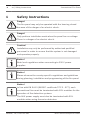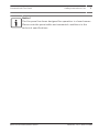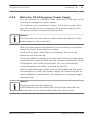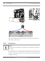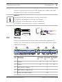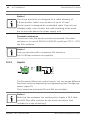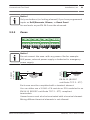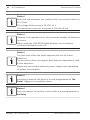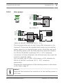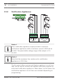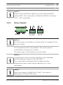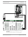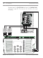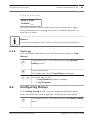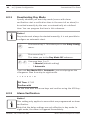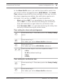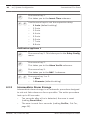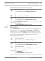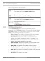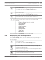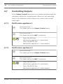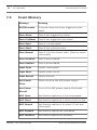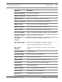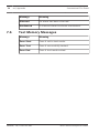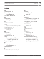
1
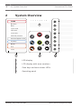
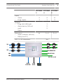
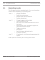
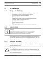
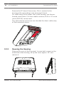
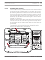
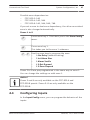
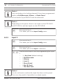
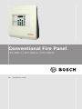
Conventional Fire Panel
FPC-500-2 / FPC-500-4 / FPC-500-8
en
Installation Guide
Conventional Fire Panel
Table of Contents | en
3
Table of contents
1
Safety Instructions
2
System Overview
2.1
Operating Levels
3
Installation
13
3.1
Scope of Delivery
13
3.2
Installation
13
3.2.1
Inserting the Cable
13
3.2.2
Opening the Housing
14
3.2.3
Installing the Housing
15
3.2.4
Mains Supply
16
3.2.5
Batteries, 24 V Emergency Power Supply
17
3.2.6
Extensions
18
3.3
Wiring
19
3.3.1
Inputs
20
3.3.2
Zones
21
3.3.3
Aux power
23
3.3.4
Notification Appliances
24
3.3.5
Relay Outputs
25
3.3.6
Extensions
26
3.3.7
External power supply
26
3.4
Initial Start-Up
29
3.4.1
Setting the Language
29
3.4.2
Setting the Time and Date
29
4
System Configuration
31
4.1
System Configuration
34
4.1.1
Setting the Date/Time
34
4.1.2
Buzzer Beep
34
4.1.3
EOL Elements
35
4.1.4
Resetting Zones
35
4.1.5
Aux Power
37
4.1.6
Faults
37
4.1.7
Level Code
38
4.1.8
Test Log
39
Bosch Sicherheitssysteme GmbH
6
8
12
2014.06 | 7.0 | F.01U.172.980
4
en | Table of Contents
Conventional Fire Panel
4.2
Configuring Delays
39
4.2.1
Deactivating Day Mode
40
4.2.2
Alarm Verification
40
4.2.3
Intermediate Alarm Storage
42
4.2.4
Delay for Mains Fault
44
4.3
Zone Configuration
44
4.4
Configuring Inputs
47
4.4.1
Input 1
48
4.4.2
Input 2 (FPC-500‑8 only)
49
4.5
Configuring Outputs
49
4.5.1
Notification Appliances
49
4.5.2
Alarm Relay
51
4.5.3
OC/Relay Extensions
52
4.6
Displaying the Configuration
53
4.7
Controlling Outputs
54
4.7.1
Notification appliance 1
54
4.7.2
Notification appliance 2
54
4.7.3
Alarm Relay
55
4.7.4
Fault Relay
55
4.7.5
OC/Relay Extension
55
4.7.6
Control all outputs
56
4.8
Resetting To Delivery State
56
5
Fault Diagnosis
58
6
Technical Data
59
6.1
Electrical Data
59
6.1.1
Communication parameters
61
6.2
Mechanical
62
6.3
Environmental Conditions
62
6.4
Information as per EN 54‑4, chapter 7.1
63
6.5
Options with requirements as per EN 54‑2:1997/A1:2006
64
7
Appendix
65
7.1
Brief Overview, Operating Level 1 and 2
65
7.2
Test menu
66
7.3
Brief Overview, Operating Level 3
67
7.4
Default Settings
74
2014.06 | 7.0 | F.01U.172.980
Bosch Sicherheitssysteme GmbH
Conventional Fire Panel
Table of Contents | en
5
7.5
Event Memory
76
7.6
Test Memory Messages
78
Index
79
Bosch Sicherheitssysteme GmbH
2014.06 | 7.0 | F.01U.172.980
6
en | Safety Instructions
Conventional Fire Panel
Safety Instructions
1
Danger!
The fire panel may only be operated with the housing closed
because of the danger of an electric shock.
Danger!
Only perform installation work when the panel has no voltage.
There is a danger of an electric shock.
Caution!
!
Installation may only be performed by authorized qualified
personnel in order to ensure that the system is not damaged
and operates properly.
Notice!
Note local regulations when connecting to 230 V power
supplies.
Notice!
Please observe the country-specific regulations and guidelines
during planning, installation and programming of the fire panel.
Notice!
In line with EN 54-13 (BOSEC certificate TCC 2 - 977), each
conventional line must be terminated with EOL modules for the
operation of fire detection systems.
The AUX power supply must also be terminated with EOL
modules when using four-wire detectors.
2014.06 | 7.0 | F.01U.172.980
Bosch Sicherheitssysteme GmbH
Conventional Fire Panel
Safety Instructions | en
7
Notice!
The fire panel has been designed for operation in closed rooms.
Please note the permissible environmental conditions in the
technical specifications.
Bosch Sicherheitssysteme GmbH
2014.06 | 7.0 | F.01U.172.980
8
en | System Overview
Conventional Fire Panel
System Overview
2
1
ALARM
2
3
Pre-Alarm
4
5
6
7
8
1
2
2
Fault
System Fault
3
Earth Fault
4
Power Fault
NAC Fault / Disabled
EVAC
5
Notification Appliance Silent
6
Day Mode
i
A CK
Disable
7
ESC
Test
8
RESET
Power
1
4
3
1
LED display
2
LCD display with zone numbers
3
Zone keys and zone status LEDs
4
Operating panel
2014.06 | 7.0 | F.01U.172.980
Bosch Sicherheitssysteme GmbH
Conventional Fire Panel
System Overview | en
9
FPC-500- FPC-500- FPC-5002
4
8
Inputs
–
Zones
2
4
8
–
Prog. inputs
1
1
2
Outputs
–
Prog. AUX (500 mA)
1
–
Alarm device, 500 mA
2
each
2
–
Relay
Extensions
no
–
Open collector (20 mA)
–
Relay (via OC)
LCD, 2 x 16 characters
1x4
2x4
Yes
Z1
.
.
.
Z8
ALARM RLY
IN1
FAULT RLY
IN2
OC (0, 4, 8)
AUX
24 V DC
Bosch Sicherheitssysteme GmbH
230
VAC
2014.06 | 7.0 | F.01U.172.980
10
en | System Overview
Conventional Fire Panel
Conventional detectors
Conventional manual call point
Visual or audible notification appliances
Conventional zones 1 to 8
Z1 ... Z8
(max. 2 on FPC-500-2, max. 4 on FPC-500-4)
Inputs (max. 1 on FPC‑500‑2 and FPC‑500‑4,
IN
max. 2 on FPC‑500‑8)
Alarm relay
ALARM RLY
Fault relay
FAULT RLY
Transistor output for extension cards
OC
(0 on FPC‑500‑2, 4 on FPC‑500‑4, 8 on
FPC‑500‑8)
AUX 24 VDC
AUX power supply
Features
–
Alarm verification: The user is prompted to verify the alarm.
–
Intermediate alarm storage: an alarm triggered by an
automatic detector is reset automatically after 20 seconds
(adjustable) by the panel. If there is an additional alarm
within 10 minutes in this zone, the notification appliances
are enabled. Otherwise the pre-alarm is reset automatically.
–
Dual-zone dependency on neighboring zones.
2014.06 | 7.0 | F.01U.172.980
Bosch Sicherheitssysteme GmbH
Conventional Fire Panel
System Overview | en
–
Dual-detector dependency for detectors in a zone.
–
Alarm counter for 999 alarms.
–
Event memory for 1000 entries.
–
Three operating levels, two of them protected with freely
11
selected code.
–
Up to 8 monitored detector zones depending on panel
version.
–
Up to 2 monitored inputs available depending on panel
version.
–
One alarm and one fault relay.
–
Up to 8 additional transistor or relay outputs, freely
programmable, depending on panel version.
–
Quick and easy programming using the keypad and LCD
display.
–
Easy operation for the end user.
–
Two monitored notification appliance outputs.
–
EN 54-13 (BOSEC certificate TCC 2 - 977) compliant system
by using EOL modules.
–
Power supply via power supply unit with thermal fuse.
–
Emergency power supply using batteries, up to 7.2 Ah,
reverse polarity protected.
–
Removable quick guide for the user on the panel.
Bosch Sicherheitssysteme GmbH
2014.06 | 7.0 | F.01U.172.980
12
2.1
en | System Overview
Conventional Fire Panel
Operating Levels
This fire panel has three operating levels. You can only perform
certain actions depending on operating level.
Level 1
Level 2
–
Display information
–
Read out event memory
–
Display faults and deactivations
–
Perform display test
–
Change language and time/date
–
Switch key tones on/off
–
Put zones in test mode and take zones out of
test mode
–
Switch off/on zones, notification appliances,
relay and transistor outputs
Level 3
–
Trigger evacuations
–
Reset panel
–
Switch between day/night mode
–
All actions of level 1
–
All settings for installing and programming the
system.
Code inputs are necessary for accessing level 2 and 3.
2014.06 | 7.0 | F.01U.172.980
Bosch Sicherheitssysteme GmbH
Conventional Fire Panel
3
Installation
3.1
Scope of Delivery
Installation | en
13
The fire panel packaging contains the following components:
–
Fire panelFPC‑500‑2/FPC‑500‑4/FPC‑500‑8
–
EOL resistors for zones and inputs
–
Battery cable set
–
Cable ties for strain relief on power supply feeder
–
Labeling strips for zones and LEDs
–
Quick Installation Guide
–
Quick Operation Guide
–
CD
–
Two plastic foam blocks for securing the batteries
Installation
3.2
Notice!
Install the fire panel in a location easily accessible to
emergency response teams (e.g. fire department).
Note permissible environmental conditions.
Install the fire panel at a height above the ground that permits
convenient operation by the user and easy reading of the LCD
display.
3.2.1
Inserting the Cable
Route the necessary cables for zones, inputs and outputs, as
well as the power supply, etc., and carefully punch out the cable
entries needed for this.
Warning!
!
Electrostatic discharge (ESD)! Electronic components could
become damaged. Ground yourself using a wrist strap or take
other suitable measures.
Bosch Sicherheitssysteme GmbH
2014.06 | 7.0 | F.01U.172.980
14
en | Installation
Conventional Fire Panel
Remove the PC board if necessary. This is secured in the
housing with a grounding screw and snap-fit hook.
For cable entry on the upper side of the housing, use the preformed round holes. For more stable insertion, M 20 x 1.5 screw
joints (PG13.5) can be used.
The cable entries on the rear are intended for direct cable entry
of flush mounted cables.
3.2.2
Opening the Housing
Remove the cover of the fire panel. Loosen both screws on the
underside of the housing, lift up the cover approx. 20° and
remove it.
2014.06 | 7.0 | F.01U.172.980
Bosch Sicherheitssysteme GmbH
Conventional Fire Panel
3.2.3
Installation | en
15
Installing the Housing
Use the panel housing to draw drill holes at the desired location
on the wall (arrows in figure below). As an option, you can use
the mounting dimensions indicated on the back of the housing.
Ensure that the housing is aligned horizontally and draw on the
holes using the built-in spirit level in the upper left corner. The
dimensions can be taken from the drilling jib on the rear of the
housing. Drill the holes.
Guide the cables routed under plaster through the punched out
cable ducts on the rear of the housing into the housing. Mount
the housing to the wall using screws. Make sure that cables are
not pinched.
Then guide the cables routed on plaster through the cable
entries to the upper side of the housing.
3x
6 x 50 mm
8mm
PZ3
S8
3x
(
8 x 40 mm)
3x
PZ3
6 x 50 mm
PZ3
Bosch Sicherheitssysteme GmbH
2014.06 | 7.0 | F.01U.172.980
16
en | Installation
3.2.4
Conventional Fire Panel
Mains Supply
The fire panel requires a 230 V mains supply for the power
supply. Route the power supply so that the line does not cross
or touch the signal line.
Use the left M 20 x 1.5 screw joint (PG13.5) on the upper side
of the panel for the 230 V mains supply.
Notice!
Note local regulations when connecting to 230 V power
supplies.
Wire up the 230 V power supply to the screw clamp provided on
the power supply unit board. Use a cable tie to ensure strain
relief of the power supply feeder in the housing above the
power supply unit.
Danger!
Only perform installation work when the panel has no voltage.
There is a danger of an electric shock.
230 VAC
50 - 60 Hz
N L
2014.06 | 7.0 | F.01U.172.980
Bosch Sicherheitssysteme GmbH
Conventional Fire Panel
3.2.5
Installation | en
17
Batteries, 24 V Emergency Power Supply
You can use two 12 V batteries with maximum 7.2 Ah each in the
housing as emergency power supply.
The batteries are connected in series. If the mains power fails,
they are used to ensure interruption-free power supply of the
fire panel and the components fed by them.
Notice!
The fire panel can also only be started with the batteries if the
power supply is disconnected.
After you have placed the batteries in the housing, secure them
using the plastic foam blocks provided.
Position the plastic foam blocks in between the top of the
batteries and the housing.
There are different emergency current back-up times depending
on the battery capacity used and the current consumption of the
components connected to the panel. You can calculate this
using the battery calculator included on the CD.
After troubleshooting a mains fault and operating the fire panel
via emergency current, the power supply unit switches back to
mains operation automatically. The batteries are charged again
automatically.
Notice!
Note the polarity of the batteries.
If the batteries are connected with the polarity reversed, the
thermal fuse on the main board of the fire panel reacts.
Bosch Sicherheitssysteme GmbH
2014.06 | 7.0 | F.01U.172.980
18
en | Installation
Conventional Fire Panel
BAT
- +
Secure the batteries with the plastic foam blocks provided so
that they cannot move.
3.2.6
Extensions
Notice!
Note that the maximum line resistance for transistor outputs is
22.5 Ohm.
The extensions are connected to the left side of the main board.
Simply connect the board to the plugs. Make sure that the plug
engages correctly.
2014.06 | 7.0 | F.01U.172.980
Bosch Sicherheitssysteme GmbH
Conventional Fire Panel
Installation | en
19
There is a groove on the top of the extensions. Make sure that
the board has been correctly installed.
Notice!
A maximum of two extensions can be connected:
FPC-500‑2: No extension can be connected
FPC-500‑4: One extension can be connected
FPC-500‑8: Two extensions can be connected
3.3
Wiring
External components such as zones, notification appliances,
inputs, etc. are wired to screw terminals attached to the upper
side of the board.
1
2
3
4
5
No Meaning
FPC‑500 FPC‑500 FPC‑500
.
-2
-4
-8
1
Inputs
1
1
2
2
Zones
2
4
8
3
Aux power supply
1
4
Notification appliance
2
5
Alarm and fault relay
Bosch Sicherheitssysteme GmbH
1/1
2014.06 | 7.0 | F.01U.172.980
20
en | Installation
Conventional Fire Panel
Notice!
The screw terminals are designed for a cable diameter of
0.8 mm and for cable cross sections of up to 1.5 mm2.
The fire panel is designed for unshielded cable. If you do use
shielded cable, only connect the cable shielding to the earth
bar on one side above the power supply unit.
Terminal resistances
The zones of the fire panels must be terminated. Use either
resistors or in case of EN 54-13 (BOSEC certificate TCC 2 - 977)
the EOL modules.
Notice!
Only use resistors with a maximum 1% tolerance.
The 3.9 kOhm resistors are supplied.
3.3.1
Inputs
3,9kΩ
+ IN1
820Ω ± 5%
The fire panel offers two control inputs. You can assign different
functions to these depending on programming (see Configuring
Inputs, page 47).
The connection terminals IN1 and IN2 are available.
Notice!
Note that the maximum line resistance for inputs is 22.5 ohm.
Use 820 Ohm ±5% resistors for the alarm resistance (not
included in scope of delivery).
2014.06 | 7.0 | F.01U.172.980
Bosch Sicherheitssysteme GmbH
Conventional Fire Panel
Installation | en
21
Notice!
Only use buttons (no locking element) if you have programmed
inputs as Drill/Evacuate, Silence, or Reset Panel.
Access levels as per EN 54‑2 must be observed.
3.3.2
Zones
Notice!
Do not connect the zone- with any power+ like for example:
AUX power, external power supply or batteries for emergency
a3,9kΩ
b+ a-|b+ a1-ZONE-2
b+ a-|b+ a1-ZONE-2
b+
3,9kΩ
power supply.
b+
a-
EOL
EOL
EN 54‑13 (BOSEC
certificate TCC 2 - 977)
Each zone must be completed with a terminal element.
You can either use a 3.9 kΩ ± 1% resistor or EOL modules for an
EN 54-13 (BOSEC certificate TCC 2 - 977) compliant
termination.
Unused zones must also be terminated with a terminal element.
Mixing different terminal elements is not allowed.
Bosch Sicherheitssysteme GmbH
2014.06 | 7.0 | F.01U.172.980
22
en | Installation
Conventional Fire Panel
Notice!
Note that the maximum line resistance for conventional zones is
22.5 Ohm.
The voltage of the zones is 20 VDC ±1 V.
The maximum current of the zones is 100 mA ±5 mA.
Notice!
Observe local regulations for the maximum number of detectors
in a zone.
When using the FLM-320-EOL4W Module, use the battery
calculator included on the CD.
Notice!
The last zone of the fire panel supports the use of 4-wire
detectors.
The fire panel does not support dual-detector dependency with
4-wire detectors.
Please use permissible external power supply units depending
on power consumption.
Notice!
Activating a manual call point in a zone programmed as "No
Delay" triggers an immediate alarm.
Notice!
Only use manual call points in zones which are programmed as
No Delay.
2014.06 | 7.0 | F.01U.172.980
Bosch Sicherheitssysteme GmbH
Conventional Fire Panel
23
Aux power
b+ a-|b+ a7-ZONE-8
3,9kΩ
b+
3,9kΩ
3.3.3
Installation | en
a-
+ AUX
+
4W
-
Non-EN54-13
V
R
P
b+
Shield
b+ a-|b+ a7-ZONE-8
EOL
a-
POWER
+U 0V
4W
FLM-320-EOL4W
CONV
b+
a-
+ AUX
+
-
EN54-13 (BOSEC certificate TCC 2 - 977)
The fire panel allows you to use 4-wire (4W) elements on the
last zone. These must be supplied with power by the auxiliary
power supply or an external power source. Both the zone and
the auxiliary power must be terminated by a terminal element.
For EN 54-13 (BOSEC certificate TCC 2 - 977) compliant
connection of 4‑wire elements, the AUX and zone lines must be
routed in separate cables.
You can either use a 3.9 kΩ ±1% resistor or EOL modules for
EN 54-13 (BOSEC certificate TCC 2 - 977) compliant
termination.
Program the reset behavior of the auxiliary power as described
in Aux Power, page 37.
Notice!
Note that the maximum line resistance for the auxiliary power is
22.5 Ohm.
Bosch Sicherheitssysteme GmbH
2014.06 | 7.0 | F.01U.172.980
24
en | Installation
3.3.4
Conventional Fire Panel
Notification Appliances
A- B+ A- B+
OUT
IN
NAC1
A- B+ A- B+
OUT
IN
NAC2
Notice!
Each notification appliance output provides connected
notification appliances with a maximum current of 500 mA at
24 VDC. The permissible voltage range of the output is 21–
29 VDC.
Notice!
Note that the maximum line resistance for notification
appliances is 22.5 Ohm.
The fire panel offers you two notification appliance circuit lines
that can be used to activate the audible notification appliances
and visual notification appliances. When there is a fire alarm, the
notification appliance circuit lines are activated depending on
programming.
2014.06 | 7.0 | F.01U.172.980
Bosch Sicherheitssysteme GmbH
Conventional Fire Panel
Installation | en
25
Notice!
Connect the notification appliances to the terminals NAC1
and/or NAC2. This connection is EN 54‑13 (BOSEC certificate
TCC 2 - 977) compliant.
3.3.5
Relay Outputs
NO C NC NO C NC
FAULT
ALARM
Notice!
The fault relay is activated in a normal state. It is opened in the
event of a fault.
The fire panel has two relay outputs. The relays work as
potential-free change-over contacts.
The alarm relay is activated by every fire alarm.
Notice!
A transmission device must be installed in the immediate
vicinity (without a space) of the FPC‑500‑x.
The connecting line between the fire panel and the
transmission device must not be exposed, as it is not
monitored.
Notice!
Both relay outputs "ALARM" and "FAULT" can switch a
maximum of 1 A @ 30 VDC each.
Bosch Sicherheitssysteme GmbH
2014.06 | 7.0 | F.01U.172.980
26
en | Installation
Conventional Fire Panel
Notice!
Note that the maximum line resistance for the relay outputs is
22.5 Ohm.
3.3.6
Extensions
The extension modules offer four connections activated by
transistors or relay.
Notice!
The relay outputs can switch a maximum of 1 A @ 30 VDC each.
The transistor outputs switch a maximum of 20 mA @ 24 VDC
each. Inductive loads are not permitted.
3.3.7
External power supply
You can use the FPP-5000 as an external power source for the
FPC-500 Fire Panel.
Notice!
Note that the FPP‑5000 housing must be installed in the direct
vicinity (without a space) of the FPC‑500‑x. The connecting line
between the FPP-5000 and the transmission device must not be
exposed, as it is not monitored.
FPC‑500‑2 and FPC‑500‑4
Wire the FPP-5000 as shown in FPC‑500‑2 and FPC‑500‑4, page
26.
Program input 1 to Ext PS Fault (see Input 1, page 48). The
relay is not included in the scope of delivery.
2014.06 | 7.0 | F.01U.172.980
Bosch Sicherheitssysteme GmbH
Conventional Fire Panel
Installation | en
+
24V
1
27
+ 24V
2
MAIN POWER
BCM-0000-B
MAIN POWER
TROUBLE
BATTERY 1
TROUBLE
BATTERY 2
BAT2
+
-
-
FAULT
-
-
Σ
-
24V
BAT1
+
AC
-
BAT
+
FAULT
TROUBLE
MAIN
+
Relais
24VDC/1A
12 V
C
NO
12 V
FPP-- 5000
820
NC
3k9
FPC‑500‑8
Wire the FPP-5000 as shown in FPC‑500‑8, page 27.
Bosch Sicherheitssysteme GmbH
2014.06 | 7.0 | F.01U.172.980
28
en | Installation
Conventional Fire Panel
Program input 1 to Ext PS Fault and input 2 to Ext Batt Fault
(see Input 1, page 48). The relays are not included in the scope
of delivery.
+
24V
1
+ 24V
2
MAIN POWER
BCM-0000-B
MAIN POWER
TROUBLE
BATTERY 1
TROUBLE
BATTERY 2
BAT2
+
-
-
FAULT
-
-
Σ
-
24V
BAT1
+
AC
-
BAT
MAIN
+
FAULT
TROUBLE
+
Relais
Relais
24VDC/1A 24VDC/1A
12 V
NO
NC
C
820
C
820
NC
3k9
3k9
NO
2014.06 | 7.0 | F.01U.172.980
12 V
FPP-- 5000
Bosch Sicherheitssysteme GmbH
Conventional Fire Panel
3.4
Installation | en
29
Initial Start-Up
As soon as the fire panel is connected to the power for the first
time, an LED and buzzer test begins. This is completed the first
time a key is pressed.
In the initial start-up, you must make the following basic
settings:
3.4.1
–
Set the language
–
Set the time and date
Setting the Language
To set the language, proceed as follows:
i
Use the arrow keys to set the desired language.
Confirm your selection in the menu with the ACK
ACK
3.4.2
key.
Setting the Time and Date
Set the current time and date. The current time and date are
important for functions such as
–
Event memory and
–
Automatic switching to night mode.
i
Use the arrow keys to set the current day.
Confirm your selection in the menu with the ACK
ACK
key.
Repeat this procedure to set the correct values for the month,
year and time.
Bosch Sicherheitssysteme GmbH
2014.06 | 7.0 | F.01U.172.980
30
en | Installation
Conventional Fire Panel
Notice!
Summer and winter time settings are not made automatically.
Make these settings manually.
If there is a total power failure, you must make the settings for
the date and time again.
2014.06 | 7.0 | F.01U.172.980
Bosch Sicherheitssysteme GmbH
Conventional Fire Panel
System Configuration | en
31
System Configuration
4
To be able to perform the actions in operating level 3, you will
need a code you can enter with the zone keys.
Notice!
The following codes are programmed in delivery status:
Operating level 2: 1234
Operating level 3: 3333
The basic settings can be found in Default Settings, page 74.
Calling up operating level 3
Press the "Code input" key.
You will be prompted to enter a code.
C O D E / Enter the code with zone keys 1 to 8.
You are in the programming menu of the system.
Caution!
!
In operating level 3, the fire panel is not operational. None of
the inputs and outputs are monitored.
Automatic exit of level 3
If you are in level 3 and no key has been pressed for 10 minutes,
the system will exit level 3 automatically.
One minute before exiting level 3, a pulse tone of the internal
buzzer indicates the time. The time up to the automatic exit of
level 3 is displayed in the LCD display.
Bosch Sicherheitssysteme GmbH
2014.06 | 7.0 | F.01U.172.980
32
en | System Configuration
Conventional Fire Panel
Exiting operating level 3
Notice!
When you exit operating level 3, the fire panel automatically
switches to night mode.
If you are in operating level 3, proceed as follows.
Press the RESET key.
You exit operating level 3 when you are at the top
RESET
level of the menu. The configuration is stored and
the inputs and outputs are activated.
RESET
ACK
–
Press the ACK key to exit operating level 3.
–
If you do not want to exit operating level 3,
press the RESET key.
Menu
Operating level 3 of the fire panel offers you the following
setting options:
–
1-System Config
–
2-Delay Config
–
3-Zone Config
–
4-Input Config
–
5-Output Config
–
6-View Config
–
7-Output Control
–
8-Config Reset
Notice!
The structure and description of menus of operating levels 1
and 2 can be found in the operating instructions.
2014.06 | 7.0 | F.01U.172.980
Bosch Sicherheitssysteme GmbH
Conventional Fire Panel
System Configuration | en
33
Notice!
The menus are described in these instructions as follows:
A hyphen between the number and the menu description "-"
shows you that it is a menu item with a submenu.
An equals sign between the number and the menu description
"=" represents a set value.
A space between the number and the menu description " " is a
value that can be set.
Preset values are always shown in bold.
Operation
You have different options for navigating in the menu of the fire
panel.
Using autoscrolling
The menus scroll automatically every 2.5 seconds to
the next menu item. If you would like to select the
ACK
menu item currently shown, simply confirm with the
ACK key.
Navigating with the zone keys
8
1
...
In the menu, each menu item has a number from 1
to 8 preceding it. Use the zone keys to select the
desired menu item in the menu. The desired menu
item does not have to be shown in the display.
Navigating with the arrow keys
i
Use the arrow keys to navigate in the menu.
Using the arrow keys stops autoscrolling in the
menus.
Confirm your selection in the menu with the ACK
ACK
key.
Bosch Sicherheitssysteme GmbH
2014.06 | 7.0 | F.01U.172.980
34
en | System Configuration
Conventional Fire Panel
Exiting submenus
In the menu and in the submenus, you can jump to a
ESC
higher level or cancel the setting using the RESET
RESET
(ESC) key.
Hold the RESET (ESC) key down for 2 seconds to
jump to the uppermost level.
4.1
System Configuration
In the System Config menu, you can specify basic settings for
your fire panel.
4.1.1
Setting the Date/Time
Press zone key 1. This takes you to the System
1
Config menu.
Press zone key 1.
1
You can now set the date and time.
To save the currently displayed value, press the ACK
key.
ACK
Repeat the steps to set the month, year, hour, and minute.
4.1.2
Buzzer Beep
Press zone key 1. This takes you to the System
1
Config menu.
Press zone key 2.
2
This takes you to the Keypad Tone submenu.
2
1
...
Press zone keys 1 or 2:
–
1=On (default setting)
–
2 Off
2014.06 | 7.0 | F.01U.172.980
Bosch Sicherheitssysteme GmbH
Conventional Fire Panel
4.1.3
System Configuration | en
35
EOL Elements
You can use EOL Devices to specify whether you want to use
resistors or EOL modules for zone termination.
Press zone key 1. This takes you to the System
1
Config menu.
Press zone key 3.
3
This takes you to the EOL Devices submenu.
3
1
...
Press zone keys 1 to 3:
–
1=Resistor (default setting, not EN 54‑13
compliant)
–
2 Only 2W Module
–
3 With 4W Module
1 2 3 4 5 6 7 8
CS TH: mA
If you select With 4W Module, you must specify the threshold
for the creeping short-circuit.
You can calculate this using the battery calculator included on
the CD.
4.1.4
Resetting Zones
In this menu, you can specify the delay times for resetting
zones. You can specify how long the zones can be disconnected
from the power and how long the stabilization time of the
detector should last. This setting is used for the zone test,
restarting the fire panel and intermediate alarm storage.
Bosch Sicherheitssysteme GmbH
2014.06 | 7.0 | F.01U.172.980
36
en | System Configuration
Conventional Fire Panel
Cut For
Press zone key 1. This takes you to the System
1
Config menu.
Press zone key 4.
4
This takes you to the Zone Reset submenu.
Press zone key 1.
1
This takes you to the Cut For submenu.
5
1
...
Press zone keys 1 to 5.
–
1 1s
–
2=5s (default setting)
–
3 10s
–
4 15s
–
5 20s
Stabilize for
Press zone key 1. This takes you to the System
1
Config menu.
Press zone key 4.
4
This takes you to the Zone Reset submenu.
Press zone key 2.
2
This takes you to the Stabilize For submenu.
5
1
...
Press zone keys 1 to 5.
–
1 1s
–
2=5s (default setting)
–
3 10s
–
4 15s
–
5 20s
2014.06 | 7.0 | F.01U.172.980
Bosch Sicherheitssysteme GmbH
Conventional Fire Panel
4.1.5
System Configuration | en
37
Aux Power
The With Zone setting relates to the last zone of the fire panel.
If the last zone is reset after a pre-alarm or alarm, the AUX
power supply is reset simultaneously.
The With Panel setting also resets the power supply each time
the fire panel is reset.
If you select Never, the auxiliary power supply is never reset.
Press zone key 1. This takes you to the System
1
Config menu.
Press zone key 5.
5
This takes you to the Aux Power submenu.
3
1
...
4.1.6
Press zone keys 1 to 3.
–
1=With Zone (default setting)
–
2 With Panel
–
3 Never
Faults
The Faults setting specifies whether faults on the fire panel are
to be displayed until the fire panel is manually reset.
Notice!
This setting does not apply to system faults.
System faults can only be reset manually.
Bosch Sicherheitssysteme GmbH
2014.06 | 7.0 | F.01U.172.980
38
en | System Configuration
Press zone key 1. This takes you to the System
1
Config menu.
Press zone key 6.
6
This takes you to the Faults submenu.
2
1
...
4.1.7
Conventional Fire Panel
Press zone key 1 or 2.
–
1=Latching (default setting)
–
2 Non Latching
Level Code
In the Level Code menu, you can specify new codes for
operating levels 2 and 3. The new code must be 4 characters
long and is displayed during entry.
Notice!
The following codes are programmed in delivery status:
Operating level 2: 1234
Operating level 3: 3333
Press zone key 1. This takes you to the System
1
Config menu.
Press zone key 7.
7
This takes you to the Code submenu.
2
1
...
–
1- Level 2 Code
–
2- Level 3 Code
1 2 3 4 5 6 7 8
Level 2 Code
Set to: ____
You are prompted to enter the new code.
2014.06 | 7.0 | F.01U.172.980
Bosch Sicherheitssysteme GmbH
Conventional Fire Panel
System Configuration | en
39
1 2 3 4 5 6 7 8
Level 2 Code
Confirm: ____
You then have to confirm the new code by entering it again.
The procedure for changing the code for operating level 3 is
exactly the same.
Notice!
If you have forgotten your code, contact your Bosch partner.
4.1.8
Test Log
You can decide whether or not the fire panel creates a Test
History.
Press zone key 1. This takes you to the System
1
Config menu.
Press zone key 8.
8
This takes you to the Test History submenu.
2
1
...
4.2
Use zone keys 1 or 2.
–
1=Log Enabled (default setting)
–
2 Log Disabled
Configuring Delays
In the Delay Config menu, you can program different delay
times for different zone programs, outputs and fault types.
2
Press zone key 2. This takes you to the Delay Config
menu.
Bosch Sicherheitssysteme GmbH
2014.06 | 7.0 | F.01U.172.980
40
en | System Configuration
4.2.1
Conventional Fire Panel
Deactivating Day Mode
Specify whether you want day mode (zones with alarm
verification start a verification time in the event of an alarm) to
be exited manually by the user or automatically at a defined
time. You can program the time in this submenu.
Notice!
Day mode must always be started manually; it is not possible to
configure an automatic start.
Press zone key 2. This takes you to the Delay Config
2
menu.
Press zone key 1.
1
This takes you to the Day Mode Off submenu.
2
1
...
Use zone keys 1 or 2.
–
1=Manual (default setting)
–
2 Automatic
If you set Day Mode Off to Automatic, you must program the
changeover time from day to night mode.
1 2 3 4 5 6 7 8
Off Time: :17:00
Confirm with
Set the time with the arrow keys and confirm using the ACK key.
4.2.2
Alarm Verification
Notice!
This setting only applies to zones that are programmed as alarm
verification.
Note that the delay settings are only effective in day mode. In
night mode, the alarm is triggered immediately.
2014.06 | 7.0 | F.01U.172.980
Bosch Sicherheitssysteme GmbH
Conventional Fire Panel
System Configuration | en
41
In the Alarm Verific menu, you set the times within which the
user must confirm a triggered alarm (ACK Within). The Invest
Time submenu specifies the time available to the user to enter
the alarm triggering area before the notification appliance is
activated. You can also use NAC 1 to specify whether:
–
Alert switches NAC 1 on immediately in the event of an
alarm. NAC 1 is then switched off during the verification
time and switched on again after the verification time.
–
With Evacuate, NAC 1 is switched off during the delay time
and only activated during the actual alarm.
Time setting for alarm acknowledgement
Press zone key 2. This takes you to the Delay Config
2
menu.
Press zone key 2.
2
This takes you to the Alarm Verific submenu.
Press zone key 1.
1
This takes you to the ACK Within submenu.
4
1
...
Use the zone keys to set the respective delay.
–
1 30 s
–
2= 60 s (default setting)
–
3 90 s
–
4 120s
Time setting for verification time
2
2
Press zone key 2. This takes you to the Delay Config
menu.
Press zone key 2.
This takes you to the Alarm Verific submenu.
Bosch Sicherheitssysteme GmbH
2014.06 | 7.0 | F.01U.172.980
42
en | System Configuration
Conventional Fire Panel
Press zone key 2.
2
This takes you to the Invest Time submenu.
8
1
...
Use the zone keys to set the respective delay.
–
1 1 min (default setting)
–
2 2 min
–
3 3 min
–
4 4 min
–
5 5 min
–
6 6 min
–
7 7 min
–
8 8 min
Notification appliance 1
Press zone key 2. This takes you to the Delay Config
2
menu.
Press zone key 2.
2
This takes you to the Alarm Verific submenu.
Press zone key 3.
3
This takes you to the NAC 1 submenu.
2
1
...
4.2.3
Press zone key 1 or 2.
–
1 Alert
–
2=Evacuate (default setting)
Intermediate Alarm Storage
Intermediate alarm storage is an automatic procedure designed
to rule out false alarms as far as possible. The entire procedure
lasts up to 60 seconds:
–
Ten seconds after a fire is detected, the zone is reset
(setting Reset After).
–
The zone is reset for x seconds (setting Cut For, Cut For ,
page 36).
2014.06 | 7.0 | F.01U.172.980
Bosch Sicherheitssysteme GmbH
Conventional Fire Panel
–
System Configuration | en
43
There is an x second stabilization phase for the elements in
the zone (setting Stabilize For, Stabilize for, page 36).
Caution!
Detectors of the FCP-320 series must not be used with
intermediate alarm storage because the detector calculates a
new standby value after the reset. This can generate an
!
increased alarm threshold. If there is a fire, this can thus delay
the trigger of an alarm.
Before using automatic fire detectors, find out from the
manufacturer whether they can be used for intermediate alarm
storage.
In this menu you can change the pre-set time values indicated
above.
Reset after
Press zone key 2. This takes you to the Delay Config
2
menu.
Press zone key 3.
3
This takes you to the Int Alarm Stor submenu.
Press zone key 1.
1
This takes you to the Reset After submenu.
4
1
...
Use the zone keys to set the respective delay.
–
11s
–
25s
–
3= 10 s (default setting)
–
4 15s
–
5 20 s
Bosch Sicherheitssysteme GmbH
2014.06 | 7.0 | F.01U.172.980
44
en | System Configuration
Conventional Fire Panel
Display total delay
Press zone key 2. This takes you to the Delay Config
2
menu.
Press zone key 3.
3
This takes you to the Int Alarm Stor submenu.
Press zone key 2.
2
This takes you to the Total Delay submenu.
The total delay is displayed.
4.2.4
Delay for Mains Fault
The Power Fault menu option enables you to specify the delay
after which an error message indicating a power supply failure
(mains or battery) is to be displayed. If the fault is resolved
before the time set here, it is no longer displayed.
Press zone key 2. This takes you to the Delay Config
2
menu.
Press zone key 4.
4
This takes you to the Power Fault submenu.
5
1
...
4.3
Use the zone keys to set the respective delay.
–
1=No Delay (default setting)
–
2 1 min
–
3 5 min
–
4 10 min
–
5 15 min
Zone Configuration
In the Zone Config menu, you can program the individual zones
of the fire panel. Depending on the panel, you can set 2, 4 or 8
zones. The following zone types are available:
2014.06 | 7.0 | F.01U.172.980
Bosch Sicherheitssysteme GmbH
Conventional Fire Panel
System Configuration | en
45
No delay (No Delay)
A zone programmed as No Delay triggers an alarm immediately.
If you are using manual call points, they must be set as No
Delay.
Notice!
Only use manual call points in zones which are programmed as
No Delay.
Int Alarm StorIntermediate alarm storage
A zone triggers an alarm. This is evaluated by the fire panel as a
pre-alarm and is not displayed. The zone is reset automatically.
If it triggers an alarm again, the panel switches immediately to
alarm. If a second alarm is not triggered, the fire panel reverts to
its normal state after 10 minutes.
Alarm verification (Alarm Verific)
Notice!
Note that the delay is only effective in day mode. In night mode,
the alarm is triggered immediately.
Notice!
If the fire panel automatically switches to night mode during an
ongoing verification time, an alarm is triggered immediately.
Notice!
If during the verification time in one zone an alarm is triggered
in another zone, which is programmed as alarm verification, an
alarm is triggered immediately.
If a zone programmed as alarm verification detects an alarm, it
triggers an alarm, which is delayed.
Bosch Sicherheitssysteme GmbH
2014.06 | 7.0 | F.01U.172.980
46
en | System Configuration
Conventional Fire Panel
The LCD display prompts you to verify the alarm. You must
confirm the alarm within a pre-defined time using the ACK key.
After this pre-defined time the verification time begins. Within
this time you must investigate the alarm triggering area and, if
necessary, trigger an alarm.
During the verification time, the panel can be reset without
triggering an alarm. After the verification time has expired, the
panel goes into the alarm state.
Dual-detector dependency (2-Det Depend)
Caution!
Detectors with connected remote displays must not be used
with the dual-detector dependency.
!
Dual-detector dependency only works with detectors that use
an alarm resistance of 820 ohm +/- 5% or 910 ohm +/- 5%.
Otherwise, in the event of a fire, proper functioning of the fire
panel cannot be guaranteed.
Notice!
The fire panel does not support dual-detector dependency with
4-wire detectors.
The zone must contain more than one detector. If one of the
detectors in the zone triggers, this is evaluated as a pre-alarm. If
an additional detector in the same zone is activated, an alarm is
triggered. The panel automatically attempts to reset the prealarm every 10 minutes. However, this is not possible if a
detector remains active. This procedure is repeated until no
more detectors are active and the panel returns to its normal
state, or until a second detector becomes active, thus elevating
the pre-alarm to an alarm.
Dual-zone dependency (2-Zone Depend)
Applies to adjacent zones, for example zones 1 and 2.
If a zone detects an alarm, this is evaluated as a pre-alarm. An
alarm is only triggered when the second zone detects an alarm.
2014.06 | 7.0 | F.01U.172.980
Bosch Sicherheitssysteme GmbH
Conventional Fire Panel
System Configuration | en
47
Possible zone dependencies:
–
FPC‑500-2: 1&2
–
FPC‑500‑4: 1&2, 3&4
–
FPC‑500‑8: 1&2, 3&4, 5&6, 7&8
If you set a zone to dual-zone dependency, the other associated
zone is also changed automatically.
Zones 1 to 8
Press zone key 3. This takes you to the Zone Config
3
menu.
Press zone key 1.
1
This takes you to the zone 1 submenu.
6
1
...
Use the zone keys to program the zone.
–
1=No Delay (default setting)
–
2 Int Alarm Stor
–
3 Alarm Verific
–
4 2-Det Depend
–
5 2-Zone Depend
Zones 2 to 8 are pre-programmed in the same way as zone 1.
You can change the settings as with zone 1.
Notice!
Zones 3 and 4 are only available on the FPC‑500‑4 and
FPC‑500‑8 panels. Zones 5–8 are only available on the
FPC‑500‑8.
4.4
Configuring Inputs
In the Input Config menu, you can program the behavior of the
inputs.
Bosch Sicherheitssysteme GmbH
2014.06 | 7.0 | F.01U.172.980
48
en | System Configuration
Conventional Fire Panel
Notice!
Only use buttons (no locking element) if you have programmed
inputs as Drill/Evacuate, Silence, or Reset Panel.
Access levels as per EN 54‑2 must be observed.
Notice!
Depending on the panel, there is one input on the FPC‑500‑2
and FPC‑500‑4, and two inputs on the FPC‑500‑8.
Press zone key 4.
4
4.4.1
This takes you to the Input Config menu.
Input 1
Press zone key 4.
4
This takes you to the Input Config menu.
Press zone key 1.
1
This takes you to the Input 1 submenu.
7
1
...
Use the zone keys to set the programming for input
1.
–
1= Not Used (default setting)
–
2 Drill/Evacuate
–
3 Silence
–
4 Level 2
–
5 Reset Panel
–
6 Ext PS Fault
–
7 Ext Batt Fault
Notice!
You do not have to confirm the input functions on the panel.
Thus use a key switch if possible to activate inputs.
2014.06 | 7.0 | F.01U.172.980
Bosch Sicherheitssysteme GmbH
Conventional Fire Panel
4.4.2
System Configuration | en
49
Input 2 (FPC-500‑8 only)
4
2
Press zone key 4.
This takes you to the Input Config menu.
Press zone key 2.
This takes you to the Input 2 submenu.
Additional settings correspond to those for Input 1.
4.5
Configuring Outputs
In the Output Config menu, you can program the behavior of the
individual fire panel outputs.
4.5.1
Notification Appliances
In the NAC submenu, you specify the behavior of the notification
appliances. You can use NAC Zones to assign the notification
appliances to particular zones. Reactive NAC specifies whether
silenced notification appliances are reactivated by a new alarm
in another zone. You can use NAC in test to specify whether the
notification appliances are activated for 15 seconds when a
zone test is performed.
Caution!
When assigning the zones to notification appliances, make sure
!
that each zone of the fire panel is assigned to at least one
notification appliance.
Zones not assigned do not trigger any alarm signaling via the
notification appliance if there is a fire.
Bosch Sicherheitssysteme GmbH
2014.06 | 7.0 | F.01U.172.980
50
en | System Configuration
Conventional Fire Panel
Notification appliance 1 zone assignment
Press zone key 5.
5
This takes you to the Output Config menu.
Press zone key 1.
1
This takes you to the NAC submenu.
Press zone key 1.
1
This takes you to the NAC Zones submenu.
8
1
Use the zone keys to select the corresponding zones
whose alarm you want to activate notification
...
appliance 1.
You can select multiple zones. If you press the zone
key again, the selection is cancelled.
Confirm your selection.
ACK
Notification appliance 2 zone assignment
See "Notification appliance 1 zone assignment", Notification
appliance 1 zone assignment, page 50.
Reactivating notification appliances
Press zone key 5.
5
This takes you to the Output Config menu.
Press zone key 1.
1
This takes you to the NAC submenu.
Press zone key 3.
3
This takes you to the Reactive NAC submenu.
2
1
...
Press zone keys 1 or 2.
1=By Other Zone (default setting)
2 No Reactivate
2014.06 | 7.0 | F.01U.172.980
Bosch Sicherheitssysteme GmbH
Conventional Fire Panel
System Configuration | en
51
Notification appliance behavior in zone test
Press zone key 5.
5
This takes you to the Output Config menu.
Press zone key 1.
1
This takes you to the NAC submenu.
Press zone key 4.
4
This takes you to the NAC in test submenu.
2
1
...
Press zone keys 1 or 2.
1 Activation
2=No Activation (default setting)
4.5.2
Alarm Relay
In the Alarm Relay submenu, you can specify the properties of
the alarm relay. These include the Silencable and Drillable
settings. You can use Silencable to specify whether the relay
can be silenced manually. Drillable specifies whether the alarm
relay is also activated during a manual alarm (Drill/Evac).
Alarm relay can be muted
Press zone key 5.
5
This takes you to the Output Config menu.
Press zone key 2.
2
This takes you to the Alarm Relay submenu.
Press zone key 1.
1
This takes you to the Silencable submenu.
2
1
...
Press zone keys 1 or 2.
1 Silencable
2=Not Silencable (default setting)
Bosch Sicherheitssysteme GmbH
2014.06 | 7.0 | F.01U.172.980
52
en | System Configuration
Conventional Fire Panel
Alarm relay follows manual alarm
Press zone key 5.
5
This takes you to the Output Config menu.
Press zone key 2.
2
This takes you to the Alarm Relay submenu.
Press zone key 2.
2
This takes you to the Drillable submenu.
2
1
...
Press zone keys 1 or 2.
1 Drillable
2= Not Drillable (default setting)
4.5.3
OC/Relay Extensions
In the OC/Relay Ext menu, you can individually set the
properties of all OC/Relay outputs. The possible settings for the
OC/Relay outputs 2 to 8 correspond to those for the first OC/
Relay . The following settings are possible:
–
Zone = Alarm: The output is activated if the zone triggers
an alarm. Here zone 1 is assigned to output 1, etc.
–
Zone Normal: If the zone is not in a normal state, the
–
Sum Alarm: When the fire panel is in an alarm state, this
output is activated. Assignment: zone 1 to output 1 etc.
output is activated regardless of the zone.
–
Sum PreAlarm: When the fire panel is in a pre-alarm state,
this output is activated regardless of the zone.
–
Sum Fault: This output is activated if there is a fault.
–
Sum Disable: If a fire panel element is disabled, this output
is activated (zones, notification appliances, relays).
–
Sum Test: This output is activated if a zone in the fire panel
is in test mode.
–
Not Used: The output is not used.
2014.06 | 7.0 | F.01U.172.980
Bosch Sicherheitssysteme GmbH
Conventional Fire Panel
System Configuration | en
5
Press zone key 5.
3
Press zone key 3.
53
This takes you to the Output Config menu.
This takes you to the OC/Relay Ext submenu.
Press zone key 1 to choose Open Collector 1.
1
8
1
...
Use the zone keys to make the corresponding
setting.
–
1=Zone = Alarm (default setting)
–
2 Zone Normal
–
3 Sum Alarm
–
4 Sum PreAlarm
–
5 Sum Fault
–
6 Sum Disable
–
7 Sum Test
–
8 Not Used
The procedure for OC/Relay 2 to 8 is the same.
4.6
Displaying the Configuration
In the View Config menu, you can display the programming of
the fire panel.
6
i
Press zone key 6.
This takes you to the View Config menu.
Use arrow keys to scroll more quickly through the
displayed programming.
Hold the arrow key down to scroll through the menu
in increments of 10 steps.
To exit the display, press the ESC key.
RESET
Bosch Sicherheitssysteme GmbH
2014.06 | 7.0 | F.01U.172.980
54
en | System Configuration
4.7
Conventional Fire Panel
Controlling Outputs
In the Output Control menu you can activate and deactivate the
individual outputs for test purposes. When you exit operating
level 3, all activations of the outputs are reset to the normal
state again.
4.7.1
Notification appliance 1
Press zone key 7.
7
This takes you to the Output Control menu.
Press zone key 1.
1
This takes you to the NAC 1 submenu.
–
ACK
RESET
Press the ACK key.
Notification appliance 1 is activated.
–
Press the RESET key.
Notification appliance 1 is deactivated.
4.7.2
Notification appliance 2
Press zone key 7.
7
This takes you to the Output Control menu.
Press zone key 2.
2
This takes you to the NAC 2 submenu.
–
ACK
RESET
Press the ACK key.
Notification appliance 2 is activated.
–
Press the RESET key.
Notification appliance 2 is deactivated.
2014.06 | 7.0 | F.01U.172.980
Bosch Sicherheitssysteme GmbH
Conventional Fire Panel
4.7.3
System Configuration | en
55
Alarm Relay
Press zone key 7.
7
This takes you to the Output Control menu.
Press zone key 3.
3
This takes you to the Alarm Relay submenu.
–
ACK
RESET
Press the ACK key.
The alarm relay is activated.
–
Press the RESET key.
The alarm relay is deactivated.
4.7.4
Fault Relay
Press zone key 7.
7
This takes you to the Output Control menu.
Press zone key 4.
4
This takes you to the Fault Relay submenu.
–
ACK
RESET
Press the ACK key.
The fault relay is activated.
–
Press the RESET key.
The fault relay is deactivated.
4.7.5
OC/Relay Extension
7
5
Press zone key 7.
This takes you to the Output Control menu.
Press zone key 5.
This takes you to the OC/Relay Ext submenu.
Bosch Sicherheitssysteme GmbH
2014.06 | 7.0 | F.01U.172.980
56
en | System Configuration
Press zone key 1.
1
This takes you to the OC/Relay 1 submenu.
–
ACK
Conventional Fire Panel
RESET
Press the ACK key.
The OC/Relay 1 output is activated.
–
Press the RESET key.
The OC/Relay 1 output is deactivated.
Continue in the same way for the Open Collector outputs 2 to 8.
4.7.6
Control all outputs
Press zone key 7.
7
This takes you to the Output Control menu.
Press zone key 6.
6
This takes you to the All submenu.
–
ACK
RESET
Press the ACK key.
All outputs are activated.
–
Press the RESET key.
All outputs are deactivated.
4.8
Resetting To Delivery State
You can use Config Reset to reset the programming of the fire
panel to the default values set when delivered.
Notice!
Resetting the fire panel deletes all of your changes to the
programming. The panel is reset to the default programming,
see Default Settings, page 74.
2014.06 | 7.0 | F.01U.172.980
Bosch Sicherheitssysteme GmbH
Conventional Fire Panel
System Configuration | en
Press zone key 8.
8
This takes you to the Config Reset menu.
–
ACK
57
RESET
Press the ACK key.
The fire panel is reset to the delivery state.
–
Press the RESET key.
You exit the menu without making changes.
Bosch Sicherheitssysteme GmbH
2014.06 | 7.0 | F.01U.172.980
58
5
en | Fault Diagnosis
Conventional Fire Panel
Fault Diagnosis
Thermal fuse, power supply unit monitoring
The integrated power supply unit is equipped with a thermal
fuse. If there is an overload this will switch off the power supply.
After the fuse cools off, it will switch the power on again.
There is a green LED on the power supply unit. This flashes
when there is an error in the power supply unit.
Thermal fuse, battery monitoring
There is a thermal fuse on the motherboard that monitors the
battery current and protects against reverse polarity.
When the fuse cools off, the battery current is switched on
again.
Updating the panel software (firmware) via USB
You can update the panel software using the USB port on the
lower left side of the main board. To do this, connect the USB
port to your computer and install the programming software
supplied on the CD. Follow the on-screen instructions.
2014.06 | 7.0 | F.01U.172.980
Bosch Sicherheitssysteme GmbH
Conventional Fire Panel
6
Technical Data | en
59
Technical Data
FPC-500 FPC-500 FPC-500
‑2
Zones
Max. number of detectors in
‑4
-8
2
4
8
64
128
256
accordance with EN 54‑2
Max. number of detectors per
32
zone in accordance with
EN 54‑2
Max. number of extensions
0
1
Prog. inputs
6.1
2
1
2
AUX output
1
Alarm device output
2
Relay
2
Electrical Data
FPC-500 FPC-500 FPC-500
‑2
Power supply voltage
‑4
-8
230 VAC +10%/-15%, 50–
60 Hz
Current consumption
AC power consumption
Operating voltage
275 mA
312 mA
80 W
21.4 VDC to 29 VDC
Imin
70 mA
Imax, a
0.7 A
Imax, b
2.3 A
Bosch Sicherheitssysteme GmbH
375 mA
2014.06 | 7.0 | F.01U.172.980
60
en | Technical Data
Conventional Fire Panel
FPC-500 FPC-500 FPC-500
‑2
‑4
-8
Zones
–
Voltage
20 VDC ±1VDC
–
Max. output current
100 mA ±5 mA
–
Max. line resistance
22.5 Ohm
–
Voltage
21 VDC to 29 VDC
–
Max. output current
500 mA ±10%
–
Max. line resistance
22.5 Ohm
–
Fuse
0.75 A @ 60 V
AUX
Notification appliance outputs
–
Voltage
21 VDC to 29 VDC
–
Max. output current
500 mA ±10% per output
–
Max. line resistance
22.5 Ohm
–
Fuse
0.75 A @ 60 V
Relay outputs
–
Breaking capacity
1 A @ 30 VDC
–
Max. line resistance
22.5 Ohm
Transistor outputs
No inductive loads
–
Breaking capacity
20 mA @ 24 VDC
–
Max. line resistance
22.5 Ohm
Recommended cable type
Unshielded cable, 0.8-mm
cable diameter, cable cross
section up to 1.5 mm2
Batteries
–
Max. inner resistance
800 mOhm
–
Max. current consumption
2.3 A
–
Fuse
5 A @ 60 V
End-point voltage
2014.06 | 7.0 | F.01U.172.980
21.4 V
Bosch Sicherheitssysteme GmbH
Conventional Fire Panel
6.1.1
Technical Data | en
61
Communication parameters
FPC-500 FPC-500 FPC-500
‑2
‑4
-8
Notification appliances
Standby
–
A-
10 V to 15 V
–
B+
0 V to 0.5 V
Alarm state
–
A-
0 V to 1 V
–
B+
21 V to 29 V
Inputs
–
Alarm resistor
820 ohm ±5%
–
EOL Resistor
3900 ohm ±1%
Zones (with resistance combination)
–
Alarm resistor
820 ohm ±5%
910 ohm ±5%
No 2-Det Depend: 680 ohm
±5%
–
EOL Resistor
3900 ohm ±1%
Zones (with EOL modules)
–
Alarm resistor
820 ohm ±5%
910 ohm ±5%
No 2-Det Depend: 680 ohm
±5%
Bosch Sicherheitssysteme GmbH
2014.06 | 7.0 | F.01U.172.980
62
6.2
en | Technical Data
Conventional Fire Panel
Mechanical
FPC-500 FPC-500 FPC-500
‑2
‑4
-8
Dimensions (H x W x D)
351 x 351 x 90 mm
Weight
2200 g, without batteries
Housing material
–
Front
ABS+PC
–
Back
ABS-FR
Housing color
6.3
–
Front
RAL 9003 (Signal White)
–
Back
PANTONE 10 C (Cool Grey)
Environmental Conditions
FPC-500 FPC-500 FPC-500
‑2
Protection category according
‑4
-8
IP 30
to EN 60529
Protection class as per
II
EN 60950
EMC interference immunity,
EN 61000-6-3
emissions
EMC interference immunity
EN 50130-4
Vibrations
EN 60068-2-6
Permitted operating
0 °C to +40 °C
temperature
Permitted storage temperature -10 °C to +55 °C (14 °F to 131
°F)
Relative humidity
2014.06 | 7.0 | F.01U.172.980
Max. 95% non-condensing
Bosch Sicherheitssysteme GmbH
Conventional Fire Panel
6.4
Technical Data | en
63
Information as per EN 54‑4, chapter 7.1
a) This is a power supply unit that is installed in the FPC‑500
Fire Panel. It provides power to the device and the connected
peripherals and is used to charge the two connectable batteries.
b) Technical data
1) Recommended power
61 W
output
2) Power supply
230 VAC +10%/-15%, 50–60 Hz
Operating voltage
26 VDC to 29 VDC
3) Communication
None
parameters
4) Fuse values
3.15 A/250 V
5) Batteries
2 x 7.0–7.2 Ah (max.) lead gel
battery
6) Max. current
2.3 A
consumption
7) Max. battery inner
800 mOhm
resistance
8) Imin
70 mA
Imax, a
0.7 A
Imax, b
2.3 A
9) Cable parameters
Battery
Cable enclosed
Board power supply
Wired ex works
230-V power supply
1.5-mm2 standard cable
Bosch Sicherheitssysteme GmbH
2014.06 | 7.0 | F.01U.172.980
64
en | Technical Data
Conventional Fire Panel
c) The power supply unit is a component of the FPC‑500 Fire
Panel and is supplied preinstalled. No additional installation
instructions are necessary.
1) Please refer to the information on environmental conditions
in this document.
2) The power supply unit is supplied preinstalled – assembly
instructions are not required.
3) For connection instructions, please refer to the FPC‑500
installation instructions.
d) The power supply unit is a component of the FPC‑500 Fire
Panel – there are no additional operating instructions.e) The
power supply unit is a component of the FPC‑500 Fire Panel –
no operation is required.f) Have maintenance and installation
work carried out regularly by trained, qualified personnel. Bosch
Sicherheitssysteme GmbH recommends carrying out a
functional and visual check at least once a year. Replace the
batteries on a regular basis. Please observe the appropriate
requirements stipulated by the local authorities etc.
6.5
Options with requirements as per EN
54‑2:1997/A1:2006
The FPC‑500 provides the following options with requirements
under EN 54‑2:1997/A1:2006
–
Alarm counter
–
Test status
–
Output for activation of fire alarm devices
–
Transmission delay
–
Dependency of fire detection status on more than one
alarm signal
–
Type A dependency
–
Type B dependency
2014.06 | 7.0 | F.01U.172.980
Bosch Sicherheitssysteme GmbH
Conventional Fire Panel
Appendix | en
7
Appendix
7.1
Brief Overview, Operating Level 1 and 2
65
Submenu
1
2
3
Menu operating level 1 and 2
i
1 Current
1
Faults
-
-
2
Disablements
-
-
3
Test
-
-
4
PreAlarm
-
-
1
Event History
-
-
2
Test History
-
-
3 Alarm Counter -
-
-
-
4 System Info
1
SW Release
-
-
2
Operation Days -
-
Events
2 History
Menu operating level 2 – code required
i
5 View Config
-
6 System Config 1
2
3
Bosch Sicherheitssysteme GmbH
-
-
-
Date/Time
-
-
Keypad Tone
1
On
2
Off
1
1-A - L
2
2-M - Z
Language
2014.06 | 7.0 | F.01U.172.980
66
7.2
en | Appendix
Conventional Fire Panel
Test menu
Submenu
1
2
3
Test menu
1 Test MMI
-
-
-
-
2 Test Zones
1
Zone 1
-
-
2
Zone 2
-
-
3
Zone 3
-
-
4
Zone 4
-
-
5
Zone 5
-
-
6
Zone 6
-
-
7
Zone 7
-
-
8
Zone 8
-
-
1
Zones
1 Zone 1
3 Dis/Enable
2 Zone 2
3 Zone 3
4 Zone 4
5 Zone 5
6 Zone 6
7 Zone 7
8 Zone 8
2014.06 | 7.0 | F.01U.172.980
2
NAC
ACK =YES ESC=No
3
Relays
ACK =YES ESC=No
4
All
ACK =YES ESC=No
Bosch Sicherheitssysteme GmbH
Conventional Fire Panel
7.3
Appendix | en
67
Brief Overview, Operating Level 3
Submenu
1
2
3
1 On
- -
2 Off
- -
1 Resistor
- -
2 Only 2W Module
- -
3 With 4W Module
- -
1 Cut For
1 1s
1 - System Config
1
1 Date/Time
2 Keypad Tone
3 EOL Devices
4 Zone Reset
2 5s
3 10 s
4 15 s
5 20 s
2 Stabilize For
1 1s
2 5s
3 10 s
4 15 s
5 20 s
5 Aux Power
6 Faults
Bosch Sicherheitssysteme GmbH
1 With Zone
- -
2 With Panel
- -
3 Never
- -
1 Latching
- 2014.06 | 7.0 | F.01U.172.980
68
en | Appendix
Conventional Fire Panel
Submenu
1
7 Code
8 Test History
2
3
2 Non Latching
- -
1 Level Code 2
- -
2 Level Code 3
- -
1 Log Enabled
- -
2 Log Disabled
- -
Submenu
1
2
3
1 Manual
- -
2 Automatic
Off Time: : 17:00
1 ACK Within
1 30 s
2 - Delay Config
2
1 Day Mode Off
2 Alarm Verific
2 60 s
3 90 s
4 120 s
2 Invest Time
1 1 min Delay
2 2 min Delay
3 3 min Delay
4 4 min Delay
5 5 min Delay
6 6 min Delay
7 7 min Delay
8 8 min Delay
2014.06 | 7.0 | F.01U.172.980
Bosch Sicherheitssysteme GmbH
Conventional Fire Panel
Appendix | en
69
Submenu
1
2
3
3 NAC 1
1 Alert
2 Evacuate
3 Int Alarm Stor
1 Reset After
1 1s
2 5s
3 10 s
4 15 s
5 20 s
4 Power Fault
2 Total Delay
- -
1 No Delay
- -
2 1 min Delay
- -
3 5 min Delay
- -
4 10 min Delay
- -
5 15 min Delay
- -
2
3
1 No Delay
- -
2 Int Alarm Stor
- -
3 Alarm Verific
- -
4 2-Det Depend
- -
5 2-Zone Depend
- -
1 No Delay
- -
Submenu
1
3 - Zone Config
3
1 Zone 1
2 Zone 2
Bosch Sicherheitssysteme GmbH
2014.06 | 7.0 | F.01U.172.980
70
en | Appendix
Conventional Fire Panel
Submenu
1
2
3
3 Zone 3
No Delay (FPC‑500‑4 /-8)
4 Zone 4
No Delay (FPC‑500‑4 /-8)
5 Zone 5
No Delay (FPC‑500‑8)
6 Zone 6
No Delay (FPC‑500‑8)
7 Zone 7
No Delay (FPC‑500‑8)
8 Zone 8
No Delay (FPC‑500‑8)
4 - Input Config
4
1 Input 1
2 Input 2
1 Not Used
- -
2 Drill/Evacuate
- -
3 Silence
- -
4 Level 2
- -
5 Reset Panel
- -
6 Ext PS Fault
- -
7 Ext Batt Fault
- -
See Input 1 (FPC‑500‑8)
Submenu
1
2
3
1 NAC Zones 1
- -
2 NAC Zones 2
- -
3 Reactive NAC
1 By Other Zone
5 - Output Config
5
1 NAC
2 No Reactivate
2014.06 | 7.0 | F.01U.172.980
Bosch Sicherheitssysteme GmbH
Conventional Fire Panel
Appendix | en
71
Submenu
1
2
3
4 NAC in test
1 Activation
2 No Activation
2 Alarm Relay
1 Silencable
1 Silencable
2 Not Silencable
2 Drillable
1 Drillable
2 Not Drillable
3 OC/Relay Ext
1 OC/Relay 1
1 Zone = Alarm
2 Zone Normal
3 Sum Alarm
4 Sum PreAlarm
5 Sum Fault
6 Sum Disable
7 Sum Test
8 Not Used
2 OC/Relay
See OC/Relay 1
3 OC/Relay
See OC/Relay 1
4 OC/Relay
See OC/Relay 1
5 OC/Relay
See OC/Relay 1
6 OC/Relay
See OC/Relay 1
7 OC/Relay
See OC/Relay 1
8 OC/Relay
See OC/Relay 1
6 - View Config
Bosch Sicherheitssysteme GmbH
2014.06 | 7.0 | F.01U.172.980
72
en | Appendix
Conventional Fire Panel
Submenu
1
2
3
1 NAC 1
ACK =On ESC=Off
- -
2 NAC 2
ACK =On ESC=Off
- -
3 Alarm Relay
ACK =On ESC=Off
- -
4 Fault Relay
ACK =On ESC=Off
- -
5 OC/Relay Ext
1 OC/Relay 1
ACK =On ESC=Off
2 OC/Relay 2
ACK =On ESC=Off
3 OC/Relay 3
ACK =On ESC=Off
4 OC/Relay 4
ACK =On ESC=Off
5 OC/Relay 5
ACK =On ESC=Off
6 OC/Relay 6
ACK =On ESC=Off
7 OC/Relay 7
ACK =On ESC=Off
8 OC/Relay 8
ACK =On ESC=Off
ACK =On ESC=Off
- -
7 - Output Control
7
6 All
8 - Config Reset
Navigation in the menu
i
Press the arrow key to scroll up in the menu.
Press the arrow key to scroll down in the menu.
Press the ACK key to confirm your selection.
ACK
2014.06 | 7.0 | F.01U.172.980
Bosch Sicherheitssysteme GmbH
Conventional Fire Panel
Appendix | en
73
Press the ESC key to exit the selection without
ESC
making a change or to jump up a menu level.
RESET
Hold the ESC key down for 2 seconds to jump to the
ESC
uppermost menu level.
RESET
8
1
...
In the menu, each menu item has a number from 1
to 8 preceding it. Use the zone keys to select the
desired menu item in the menu.
Bosch Sicherheitssysteme GmbH
2014.06 | 7.0 | F.01U.172.980
74
7.4
en | Appendix
Conventional Fire Panel
Default Settings
Menu item
Default setting
1 System Config
2 Keypad Tone
On
3 EOL Devices
Resistor
4 Zone Reset
1 Cut For
5s
2 Stabilize For
5s
5 Aux Power
With Zone
6 Faults
Latching
8 Test History
Log Enabled
2 Delay Config
1 Day Mode Off
Manual
2 Alarm Verific
1 ACK Within
60 s
2 Invest Time
1 min
3 NAC 1
Evacuate
3 Int Alarm Stor
1 Reset After
4 Power Fault
10 s
No Delay
3 Zone Config
1 Zone 1
No Delay
...
4 Input Config
2014.06 | 7.0 | F.01U.172.980
Bosch Sicherheitssysteme GmbH
Appendix | en
Conventional Fire Panel
Menu item
75
Default setting
1 Input 1
Not Used
...
5 Output Config
1 NAC
1 NAC Zones
All zones
2 NAC Zones
All zones
3 Reactive NAC
By Other Zone
4 NAC in test
No Activation
2 Alarm Relay
1 Silencable
Not Silencable
2 Drillable
Not Drillable
3 OC/Relay Ext
1 OC/Relay 1
Bosch Sicherheitssysteme GmbH
Zone = Alarm
2014.06 | 7.0 | F.01U.172.980
76
7.5
en | Appendix
Conventional Fire Panel
Event Memory
Message
Meaning
Drill/Evacuate
A manual alarm has been triggered on the
panel.
Zone Alarm
Zone # has triggered an alarm.
Zone PreAlarm
Zone # has triggered a pre-alarm.
Zone Open
Zone # is interrupted.
Zone Short
Zone # has a short-circuit.
Zone Normal
Zone # is in the normal state. (Fault or alarm
eliminated)
Zone Disabled
Zone # was enabled.
Zone Enabled
Zone # was enabled.
Input Open
Input # interrupted.
Input Short
Input # short-circuit.
Input Normal
Input # normal.
Aux Power
Short-circuit in the AUX power supply
Short
Aux Power
Error in the AUX power supply eliminated.
Normal
NAC Open
Notification appliance #, line interrupted
NAC Short
Notification appliance #, short-circuit on line.
NAC Normal
Notification appliance # normal. (Fault was
eliminated)
NAC Enabled
Notification appliances re-enabled.
NAC Disabled
Notification appliances disabled.
2014.06 | 7.0 | F.01U.172.980
Bosch Sicherheitssysteme GmbH
Conventional Fire Panel
Appendix | en
Message
Meaning
Relays Enabled
Relays re-enabled.
77
Relays Disabled Relays disabled.
Battery Fault
Fault in the battery power supply.
Battery Restore Battery power supply was restored.
Mains Fault
Fault in the 230 V power supply.
Mains Restore
230 V power supply was restored.
Ext PS Fault
Fault in external power supply unit.
Ext PS Normal
Fault in external power supply unit resolved.
Ext BATT Fault
Fault in external battery.
Ext BATT
Fault in external battery resolved.
Normal
Sys Load Fault
Current consumption of panel and all
connected peripherals is above 3.5 A.
Sys Load
Current consumption is back in permitted
Normal
range.
System Fault
System fault
Panel boot-up
Panel has been restarted.
Reset Panel
Panel has been reset.
Night Mode
Panel has switched to night mode.
Day Mode
Panel has switched to day mode.
Earth Fault
Grounding fault.
Earth Normal
Fault in grounding resolved.
Level Enter
Operating level # entered.
Level Exit
Operating level # exited.
Bosch Sicherheitssysteme GmbH
2014.06 | 7.0 | F.01U.172.980
78
7.6
en | Appendix
Conventional Fire Panel
Message
Meaning
Silenced
An alarm has been silenced.
Unsilenced
A silenced alarm has been reactivated.
Test Memory Messages
Message
Meaning
Zone Start
Zone # set to test mode.
Zone Test
Zone # successfully tested.
Zone End
Zone # test mode exited.
2014.06 | 7.0 | F.01U.172.980
Bosch Sicherheitssysteme GmbH
Conventional Fire Panel
Index | en
79
Index
A
Access model, 12
H
Housing
Installing, 15
Alarm relay
Open, 14
Programming, 51
AUX;Reset settings, 37
B
I
Input, 20
Programming a function, 48
Buzzer beep
Setting, 34
Installation location, 13
C
Intermediate alarm storage
Code
Invest time
Cable entries, 13
Change;Password:Change, 38
Code;Password, 31
Confirmation time
Setting, 41
D
Setting, 42
Setting, 41
M
Mains supply, 16
N
Navigating
Date/Time
Setting, 34
Default settings, 74
Delay
Arrow keys, 33
Navigation, 72
Zone keys, 33, 73
Notification appliance, 24
Power supply fault;Power
Assignment to zones, 50
supply:Fault delay, 44
Behavior in zone test, 51
Delay settings, 39
Specifying reactivation, 50
E
Emergency power
supply;Batteries, 17
Extensions, 18
F
Fault handling;Store faults, 37
Bosch Sicherheitssysteme GmbH
2014.06 | 7.0 | F.01U.172.980
80
en | Index
O
Operating level 3
Conventional Fire Panel
Z
Zone reset
Automatic exit, 31
Disconnection duration, 36
Calling up, 31
Setting times, 35
Exiting, 32
Stabilization time, 36
Operation, 33
Outputs
Activation for testing, 54
Programming, 49
Zone termination
Setting, 35
Zone types, 44
dual-detector
Programming;Transistor
dependency;dual-detector
dependency, 46
outputs:Programming;Relay
outputs:Programming, 52
Dual-zone dependency;dualzone dependency, 46
P
Programming
Intermediate alarm
storage;Intermediate alarm
Resetting to delivery state, 56
R
Relay outputs;Alarm relay;Fault
storage, 45
Manual alarm
verification;Manual alarm
relay, 25
S
Screw terminals, 19
Submenus
Exiting, 34
verification, 45
No delay;No delay, 45
Zones
Specify zone type, 47
T
Terminal resistance;Terminal
element;EOL module;End-OfLine module, 20, 21
Test log
Setting, 39
2014.06 | 7.0 | F.01U.172.980
Bosch Sicherheitssysteme GmbH
Bosch Sicherheitssysteme GmbH
Robert-Bosch-Ring 5
85630 Grasbrunn
Germany
www.boschsecurity.com
© Bosch Sicherheitssysteme GmbH,
2014