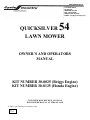
1
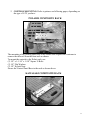
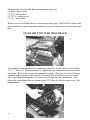
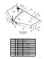
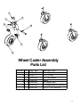
1701 38TH AVE W
PO BOX 229
SPENCER, IA 51301
FAX: 712-262-0248
SERVICE: 800-841-2222
E-MAIL: [email protected]
54
QUICKSILVER
LAWN MOWER
OWNER’S AND OPERATORS
MANUAL
KIT NUMBER 30-0025 (Briggs Engine)
KIT NUMBER 30-0125 (Honda Engine)
CUSTOMER MUST RECEIVE A COPY OF
THIS OWNERS MANUAL AT TIME OF SALE
© 2001 Cycle Country Accessories Corp.
Rev. 2
3/12/07
1701 38TH AVE W
PO BOX 229
SPENCER, IA 51301
FAX: 712-262-0248
SERVICE: 800-841-2222
E-MAIL: [email protected]
ONE YEAR LIMITED WARRANTY
For the period of one year from the purchase date Cycle Country Accessories
Corporation will replace for the original purchaser, free of charge, any part or parts, when
found, upon examination by Cycle Country Accessories Corporation, to be defective in
material, workmanship, or both.
All transportation cost incurred by the purchaser in submitting the material to
Cycle Country Accessories Corporation for replacement under this warranty must be
borne by the purchaser. If Cycle Country Accessories Corporation determines that the
product must be returned to the factory for credit please call 1-800-841-2222 for an RMA
number and shipping instructions.
The warranty does not apply to parts that have been damaged by accident,
alteration, abuse, improper lubrication, normal wear, or other causes beyond Cycle
Country Accessories Corporation’s control. Products such as engines, electric motors,
and actuators may carry an original manufacturer’s warranty. Please call Cycle Country
Accessories Corporation for information.
2
THANK YOU FOR YOUR PURCHASE OF OUR
QUICKSILVER
54
FINISH MOWER
ENCLOSED IN THIS KIT IS THE
MOWER DECK ASSEMBLY
YOU CAN CHOOSE TO MOUNT THE MOWER ON THE FRONT OF YOUR ATV (A) OR PULL
THE MOWER BEHIND YOUR ATV (B).
A. TO HAVE A COMPLETE FRONT MOUNT MOWER ASSEMBLY, YOU MUST HAVE AT
LEAST THREE ITEMS:
1. MODEL SPECIFIC ATTACHING HARDWARE KIT TO ATTACH
THE LAWN MOWER/PUSH TUBE TO ATV. (YOU ALREADY
HAVE THIS IF YOU HAVE OUR WP-5 OR WP-2000 SNOW
BLADE PUSH TUBE SYSTEM.)
2. LAWN MOWER PUSH TUBE & PIVOT #30-0028
3. MOWER DECK ASSEMBLY #30-0025 or #30-0125
B. TO HAVE A COMPLETE TOW BEHIND MOWER ASSEMBLY, YOU MUST HAVE THE
TWO FOLLOWING ITEMS:
1. TOW BEHIND KIT #30-0080
2. MOWER DECK ASSEMBLY #30-0025 or #30-0125
3
BEFORE OPERATING THE QUICKSILVER 54 LAWN MOWER—READ AND UNDERSTAND
ALL OPERATING AND ASSEMBLY INSTRUCTIONS COVERED IN THIS MANUAL.
WARNING
The QUICKSILVER 54 is a powerful cutting machine and is capable of amputating hands and feet and
can also throw materials that can cause damage to you or your property.
PLEASE READ ALL INSTRUCTIONS IN THIS MANUAL VERY CAREFULLY.
IF YOU HAVE ANY QUESTION PLEASE CONSULT YOUR DEALER OR
CYCLE COUNTRY DIRECTLY AT 1-800-841-2222
IMPORTANT PRECAUTIONS:
DO NOT ALLOW children to ride on the ATV or lawn mower at any time,
DO NOT ALLOW children to operate the lawn mower.
Only responsible persons with mature judgment should be allowed to operate the lawn mower.
Read and follow all instructions.
Wear appropriate protective clothing when mowing such as boots and long pants.
Never operate under the influence of drugs or alcohol.
Know how to stop engine and blades quickly in case of emergency.
Keep all people and pets at a safe distance from lawn mower.
All shields, switches and blade controls must be in proper position and functional before using mower.
Clear the area to be mowed of all wire, rocks, and other objects that could cause injury if thrown by the
blades.
Shut off engine before leaving the ATV. Remove key when leaving the ATV and mower unattended.
Do not try to operate the lawn mower unless properly seated on the ATV.
Stop engine, and disconnect spark plug wire before attempting to unclog grass or leaves from the
mower.
Do not operate with belt covers removed for any reason.
Service and make adjustments only when the engine is stopped.
Tighten all bolts, nuts, and screws frequently and replace worn or broken parts.
4
Handle gasoline with care!!! Never remove cap while engine is running. Fill tank outdoors only with
engine stopped and cool.
Stop engine except when cutting grass.
Mow in reverse only after careful observation of entire area behind the lawn mower. DO NOT mow in
reverse unless absolutely necessary.
OPERATION INSTRUCTIONS
THE QUICKSILVER 54 IS DESIGNED TO MOW AT APPROXIMATELY 5 MPH.
DO NOT EXCEED 5 MPH WITH THE MOWER ATTACHED TO THE ATV.
1. Check over your ATV to insure that it is in good working order.
2. Check over the lawn mower. All guards and covers must be in proper position.
3. Check exterior surfaces of the lawn mower. Clean up any accumulation of grass, oil, or gas
especially around air intakes and cooling fins on the engine.
4. Check engine oil and add as needed. (SEE ENGINE OWNER’S MANUAL.)
5. Fill fuel tank outdoors where fumes will dissipate.
MAINTENANCE
1. Stop engine and disconnect spark plug wire before attempting to unclog lawn mower.
2. Service the lawn mower and make adjustments only when the engine is stopped.
3. Tighten all nuts, bolts, and screws frequently and check, adjust, and replace parts as needed.
4. Maintain proper belt tension at all times.
5. Check exterior surfaces of the lawn mower. Clean up any accumulation of grass, oil, or gas
especially around air intakes and cooling fins on the engine. Failure to keep engine clean and
free from cooling air restrictions will cause engine to run hot and may cause severe damage.
6. Check engine oil and add as needed. (SEE ENGINE OWNER’S MANUAL)
7. Recheck belt tensioner idler height periodically and at each oil change.
8. Grease tensioner arm, wheel and wheel spindle zerks at each oil change.
9. Cutting Blade Service: Before doing any work on the blades, remember to disconnect the spark
plug wire and secure it away from the spark plug to prevent unintentional starting. Have blades
5
replaced if they become bent or chipped from impacting solid objects or when the cutting surface
becomes dull from extended use.
10. Check the blade and spindle retaining nuts and bolts at frequent intervals to make sure the blades
and spindles remain tight.
STARTING – STOPPING
1. To start engine, place throttle in choke position, turn key to start. When engine starts, move
throttle to idle position.
2. To stop engine, move throttle or key to stop position.
WARNING! THE ONLY WAY TO INSURE THAT THE BLADES ARE
STOPPED IS TO SHUT OFF THE ENGINE! DO NOT RELY ON THE
CLUTCH TO DISENGAGE THE BLADES WITH THE ENGINE
RUNNING!!!
OPERATIONAL CHECKS
¾ OIL MUST BE PUT IN THE ENGINE BEFORE STARTING!
¾ Prepare the engine according to the ENGINE OWNER’S MANUAL.
¾ Install the Attaching Hardware according to instructions.
¾ Re-check belt alignment and tension frequently.
¾ Periodically check all nuts and bolts for tightness.
¾ Check blade and spindle nuts and bolts at frequent intervals.
6
ASSEMBLY INSTRUCTIONS:
DECK & FRAME
1. Disassemble shipping crate sides and top leaving the mower deck and main frame
on the crate base.
2. Lift and rotate the main frame, setting it down so the three lift brackets on the main
frame are above the three eyebolts in the mower deck. Insert each of the eyebolts
up through the brass bushings. Install one 1/2” SAE flat washer on each eyebolt
and then the PUR1566 spring followed by another 1/2” SAE flat washer and then
screw down the CYC3478 crank handles to raise the mower deck. See picture
below.
The handle stop is to keep the handle from spinning when the mower is in use. Included
with the parts bag are three rings. Drop one ring over each of the crank handles to
restrict movement and ensuring effectiveness of the handle stop.
7
3. Attach and secure the left and right link arms to the main frame using the bolts and
bushings provided. NOTE: The link arm goes on the inside of the tab on the main
frame.
Link arm goes on the
inside of the tab.
4. Attach the solenoid-starter relay assembly to the mower tube frame (right side) as
shown in picture below. Note: Not included for Honda equipped mowers.
8
BELT ROUTING AND ADJUSTMENT
1. The spring end-to-end length is set at 5-1/4” from the factory. The spring length
MUST BE checked after running 15 minutes and again after mowing for an
hour. Check spring length again after a few hours of mowing. After the belt is
‘RUN-IN’, the correct spring length is 4-3/4”-5”. Measurements are taken from
the spring ends. See picture below.
Measure total spring length
from end to end
Replacement Belt: PUR1546
9
OPTIONAL 30-0028 PUSH TUBE ASSEMBLY
1. If you have purchased the optional 30-0028 lawn mower push tube assembly,
assemble it at this time as per the instructions enclosed in that package. NOTE:
The pivot in that kit is installed on the push tube assembly UPSIDE DOWN FOR
PACKAGING PURPOSES. Remove it and reinstall it as shown in the drawing
below.
2. Attach the pivot/push tube assembly to the Quicksilver 54 frame as show above.
3. Attach the push tube assembly to the push tube attaching brackets on the ATV,
using the 3/8” x 1” clevis pins and #3 hairpins included with the attaching bracket
kit.
WIRING AND CONTROLS
1. WIRE ATTACHMENT. Using a wire tie or electrical tape, attach the ATV
wiring harness to the front of the ATV brush guard so that the gray connector
hangs free about 4” out from the front of the ATV. Route the Red (+) positive
cable along the frame of the ATV to the battery, using care to route it away from
exhaust system and areas where it might chafe or burn. Use the most direct route.
Cut off the excess cable. Attach the ring terminal eyelet connector to the end of
the cable and attach to the positive (+) terminal of the battery. Secure wire along
the frame using wire ties or electrical tape. Attach the Black (-) negative ground
cable at the nearest ground point on the ATV. (Example: a front bumper frame
bolt.) Connect the gray ATV wiring harness to the gray mower wiring harness.
10
2. CONTROL MOUNTING: Refer to pictures on following pages, depending on
the type of ATV you have.
POLARIS COMPOSITE RACK
The mounting of the control panel base to the Polaris rack requires the customer to
remove the tube rail from the front rack as shown.
To mount the controls to the Polaris rack, use:
(2) 1/4” x 1-1/16” x 1-5/8” Square U-Bolts
(2) 1/4” Flat Washers
(2) 1/4” Nylock Nuts
Secure the Control Panel Base to the rack as shown above.
KAWASAKI COMPOSITE RACK
11
To mount the controls to the Kawasaki composite rack, use:
(2) 8mm x 50mm bolts
(2) 5/16” lock washers
(2) 7/8” U-clamp spacers
(2) 5/16” flat washers
Remove the two hold down bolts as shown on previous page. Place the flat washers and
spacers under the control panel base and fasten securely using the lock washer and metric
bolt.
STANDARD TYPE TUBE FRONT RACK
To mount the control panel base to a tube type front rack, use the vinyl covered clamps,
1/4” x 1” bolts, 1/4” flat washers and 1/4” nylock nuts provided and secure it in at least
two points. Refer to the pictures for suggested methods. There are two sizes of clamps
included in the kit to allow the controls to be mounted to virtually any type tube rack.
The control panel is designed to be easily removed using the two clamp knobs. This
allows the control panel base to remain on the ATV when the mower is not in use. See
picture below.
12
10
9
8
7
1
6
11
2
4
6
3
5
11
1
12
Deck Assembly
Parts List
ITEM NO. QTY. PART NO. DESCRIPTION
1
1 CYC3457 Mower Deck
2
1 CYC3495 Eyebolt
3
1 PUR1112 1/2" x 2-1/2" Bolt
4
1 PUR1261 1/2" Nylock Nut
5
1 PUR1145 3/8" x 2" Bolt
6
8 PUR1272 3/8" Nylock Nut
7
1 CYC3472 Motor Mount Support Bar
8
1 PUR1148 3/8" x 2-3/4" Bolt
9
2 CYC3479 Belt Idler Spacer
10
1 PUR1551 Idler Pulley
11 14 PUR0250 3/8" Flat Washer
12
6 PUR1140 3/8" x 1" Bolt
13
3
4
13
12
11
10
15
14
5
9
8
7
1
6
16
2
Main Frame Assembly
Parts List
ITEM NO.
1
2
3
4
5
6
7
8
9
10
11
12
13
14
15
16
14
QTY.
1
4
4
6
3
3
3
3
6
3
3
3
6
3
4
4
PART NO.
CYC3461
PUR1603
PUR1077
PUR1848
PUR1129
PUR1265
PUR1591
PUR1556
PUR1235
CYC3476
CYC3478
PUR1590
PUR1353
PUR1813
PUR1474
PUR1354
DESCRIPTION
Main Frame
Grease Zerk
1-1/8" x 1-1/2" Cap
Mount Bracket Spacer
1/4 x 3-1/4" Bolt
1/4" Nylock Nut
1/2" x 3/4" x 1" Shoulder Bushing
QS54 Spring Height Adjustment
1/2" Flat Washer SAE
Crank Channel
Crank Handle
Knob
3/8" Push Nut
Ring
Plastic Button
3/8" Flat PAL Nut
7
6
1
5
2
3
4
Wheel Caster Assembly
Parts List
ITEM NO. QTY.
1
4
2
4
3 24
4
4
5
4
6
8
7
4
PART NO.
CYC3484
PUR1171
PUR1245
PUR1543
PUR1283
PUR1240
PUR1364
DESCRIPTION
Wheel Spindle
5/8" x 5" Bolt
5/8" Flat Washer
Wheel
5/8" Nylock Nut
14 Gauge Machine Bushing
3/16" x 1-1/8" Roll Pin
15
9
8
5
7
6
4
2
3
1
Corner Wheel Assembly
Parts List
ITEM NO. QTY.
1
2
2
2
3
2
4
2
5
1
6
2
7
4
8
4
9
1
16
PART NO.
PUR1170
PUR1547
PUR1246
PUR1258
CYC3491
PUR1283
PUR1189
PUR1275
CYC3493
DESCRIPTION
5/8" x 3-1/2" Bolt
Corner Wheel
Flatwasher 5/8 SAE
5/8" Jam Nut
Left Corner Wheel Bracket
5/8" Nylock Nut
5/16" x 1" Carriage Bolt
5/16" Nylock Nut
Right Corner Wheel Bracket
21
22
23
20
19
16
7
Use Fine Thread Bolt
and Lock Washer
for Honda Engine
2 Places
18
17
25
Note: Not included
for Briggs engine
13
4
5 4
12
3
11
26
24
2
15
Motor Mount Assembly
Parts List
NO. QTY. PART NO.
1
1 CYC3471
2
2 PUR1178
3
2 PUR1233
4
4 PUR1260
5
2 CYC3495
6
2 PUR1189
7
2 CYC3475
8
4 PUR1360
9
4 PUR1244
10
8 PUR1275
11
3 PUR1156
12
1 PUR1159
13
1 PUR1278
14
2 PUR1932
15
2 PUR1293
16
1 PUR1229
DESCRIPTION
Motor Mount
1/2" x 2" Carriage Bolt All Thread
1/2" Flat Washer
1/2" Center Lock Nut Yellow
Eyebolt
5/16" x 1" Carriage Bolt
Link Arm
Sleeve Bushing
5/16" Flat Washer
5/16" Nylock Nut
5/16" x 1-1/2" Bolt
5/16" x 1-3/4" Bolt
5/16" Serrated Flange Hex Nut
5/16" x 1" Fine Thread Bolt
5/16" Lock Washer
7/16" x 1" Allen Head Bolt
6
1
9
14
8
NO. QTY. PART NO.
17
1 PUR1295
18
1 PUR1248
19
1 PUR0678
20
3 PUR1301
21
1 CYC5442
22
1 PUR1531
23
1 PUR1542
24
1 PUR1272
25
1 PUR1322
26
1 PUR0250
27
2 PUR1155
27
10
DESCRIPTION
7/16" Lock Washer
7/16" Flat Washer
Engine Drive Clutch
1" x 1-1/2" Machine Bushing
Bushing Mower Clutch QS Mower
Briggs Engine
Honda Engine
3/8" Nylock Nut
3/8" x 1" Flat Head Bolt
3/8" Flat Washer
5/16" x 1" Bolt
17
1
8
2
4
7
6
5
3
Belt Cover Assembly
Parts List
ITEM NO.
1
2
3
4
5
6
7
8
18
QTY.
1
1
6
18
12
6
6
6
PART NO. DESCRIPTION
CYC3501 Right Belt Cover
CYC3502 Left Belt Cover
PUR1184 1/4" x 4" Carriage Bolt Full Thread
PUR1237 1/4" Flat Washer
PUR1848 Mount Bracket Spacer
PUR1265 1/4" Nylock Nut
PUR1589 1/4" x 1" x 3/8" Rubber Stop
PUR1334 1/4" Nut
8
4
10
7
5
6
1
4
3
9
2
11
14
12
13
Belt Tensioner Assembly
Parts List
ITEM NO. QTY. PART NO.
1
1 CYC3481
2
1 PUR1152
3
1 CYC3479
4
3 PUR0250
5
6 PUR1240
6
1 PUR1603
7
1 CYC3480
8
2 PUR1272
9
1 PUR1143
10
1 PUR1551
11
1 PUR1437
12
1 PUR1216
13
1 PUR1244
14
1 PUR1275
DESCRIPTION
Belt Tensioner
3/8" x 3-1/4" Bolt
Belt Idler Spacer
3/8" Flat Washer
14 Gauge Machine Bushing
Grease Zerk
Belt Tensioner Bushing
3/8" Nylock Nut
3/8" x 1-3/4" Bolt
Idler Pulley
Belt Tension Spring
5/16" x 4-1/4" Eye Bolt
5/16" Flat Washer
5/16" Nylock Nut
19
1
2
3
4
5
6
7
8
9
10
11
Blade Spindle Assembly
Parts List
20
ITEM NO. QTY.
1
9
2 21
3
3
4
3
5 12
6
3
7
3
8
3
9
3
10
3
11
3
PART NO.
PUR1158
PUR1293
PUR1552
PUR1544
PUR1155
PUR1553
PUR1554
PUR1545
PUR1225
PUR1288
PUR1228
DESCRIPTION
5/16" x 1-1/4" Bolt
5/16" Lock Washer
Blade Drive Pulley
Pulley Spacer
5/16" x 1" Bolt
Spindle Assembly
Friction Disc
Mower Blade
17/32" Fender Washer
1/2" Lock Washer
1/2-20 X 1 HH G5 Bolt
10
17
3
16
2
7
9
4
15
8
12
1
Note: Not all parts
used in every
application
11
5
13
7
Control Panel Assembly
Parts List
ITEM NO. QTY. PART NO.
1
1 CYC3489
2
1 CYC3490
3
2 PUR1130
4
2 CYC5397
5
2 PUR1348
6
2 PUR1412
7
6 PUR1237
8
4 PUR1265
9
2 PUR1293
10
2 PUR1315
11
2 CYC0848
12
2 PUR1118
13
2 PUR1609
14
2 PUR1607
15
1 PUR1600
16
2 PUR1392
17
2 PUR1063
14
6
DESCRIPTION
Control Panel Base
Control Panel Cover
1/4" x 3/4" Bolt
Clamp Knob
1/4" x 20 Nut Retainer
1/4" x 1-1/16" x 1-5/8" Sq. U-Bolt
1/4" Flat Washer
1/4" Nylock Nut
5/16" Lock Washer
8 x 50 Metric Bolt
7/8" U-Clamp Spacer
1/4" x 1 " Bolt
Clamp 3/4" Vinyl Coated
Clamp 13/16" Vinyl Coated
Ignition Switch
10 x 1/2" Slotted Tapping Screw
Clamp Knob Sticker
21
1
3
11
4
2
5
7
9
10
6
Note: Items 5-10 are
not included with
Honda engine.
12
No. 11 for use with Honda engine only
Wiring & Cable Assembly
Parts List
22
8
ITEM NO. QTY.
1
1
2
1
3
1
4
1
5
2
6
1
7
1
8
2
9
2
10
2
11
1
12
1
PART NO.
PUR1549
PUR1601
PUR1548
PUR1374
PUR1119
PUR1598
PUR1550
PUR1589
PUR1237
PUR1265
PUR1390
PUR1546
DESCRIPTION
Throttle Cable
ATV Wiring Harness
LM Wiring Harness
Ring Term inal 5/16 8Ga.
1/4" x 1-1/2" Bolt
Solenoid-Stater Relay
Solenoid Cover
1/4" x 1" x 3/8" Rubber Stop
1/4" Flat Washer
1/4" Nylock Nut
M ale Bullet Connector
Dayco V-Belt
Cycle Country Accessories Corporation has been a world-renowned manufacturer of quality
ATV products since 1981 and we hope you will enjoy your new Cycle Country accessory.
We’re the Industry Snow Blade leader:
42”, 48”, 54”, 60” & 72” Straight Blades
52” & 60” State Plows
Power ‘V’ Blade
If a winch is what you must have, then you’ve come to the right place:
1500lb, 2500lb and 3000lb Winches
We also have an extensive line of winch mounts for both Cycle Country and Warn winches
If you need to haul more gear on your quad, check out our baskets:
Front Basket
Rear Basket
Rear Drop Basket
Rear Drop Basket with Tail Gate
If you need to mow the trail before you go riding one of these will help:
Our 54” finish cut Quick Silver54 can be mounted in front or towed behind your ATV
The 48” Rough Cut will handle your toughest mowing jobs
If you are into deer hunting and want to make a food plot, you will love our 3 Point
Hitch & Implements:
Rear Blade
Moldboard Plow
Furrower
Rake
Cultivator
Disk Harrow
Spreader
And many more accessories to help you Work Hard and Play Hard:
For more information call us at 1-800-841-2222, or on the web at www.cyclecountry.com
23