1
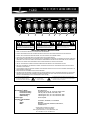
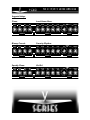
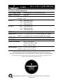
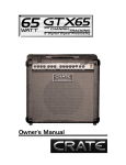
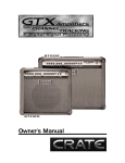
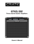
VFX 5112/5212 Guitar Amplifier
INPUT
VOLUME
0
10
TREBLE
0
MID
10
0
BASS
10
0
10 Channel 0
Select
Channel A
1
2
3
4
GAIN
5
6
TREBLE
10
0
MID
10
0
10
Channel B
7
8
9
CAUTION
PRECAUCION
ATTENTION
RISK OF ELECTRIC SHOCK
DO NOT OPEN
RIESGO DE CORRIENTAZO
NO ABRA
RISQUE D'ELECTROCUTION
NE PAS OUVRIR
WARNING: TO REDUCE THE RISK OF FIRE OR ELECTRIC
SHOCK, DO NOT EXPOSE THIS APPARATUS TO RAIN OR MOISTURE. TO REDUCE THE RISK OF ELECTRIC SHOCK, DO NOT
REMOVE COVER. NO USER-SERVICEABLE PARTS INSIDE.
REFER SERVICING TO QUALIFIED SERVICE PERSONNEL.
ADVERTENCIA: REDUCIR EL RIESGO DE FUEGO O CHOQUE ELÉCTRICO, NO LE EXPONE DE ESTE APARATO A LLUVIA O HUMEDAD. PARA
DISMINUOIR EL RIESGO DE CORRIENTAZO. NO ABRA LA CUBIERTA.
NO HAY PIEZAS ADENTRO QUE EL USARIO PUEDO REPARAR DEJE
TODO MANTENIMIENTO A LOS TECHNICOS CALIFICADOS.
ATTENTION: POUR REDUIRE D'ELECTROCUTION NE PAS
ENLEVER LE COUVERCLE. AUCUNE PIECE INTERNE N'EST
REPRABLE PAR L'UTILISATEUR. POUR TOUTE REPARATION,
S'ADRESSER A UN TECHNICIEN QUALIFIE.
IMPORTANT SAFETY INSTRUCTIONS
•
•
•
•
•
READ, FOLLOW, HEED, AND KEEP ALL INSTRUCTIONS AND WARNINGS.
DO NOT OPERATE NEAR ANY HEAT SOURCE AND DO NOT BLOCK ANY VENTILATION OPENINGS ON THIS APPARATUS.
DO NOT USE THIS APPARATUS NEAR SPLASHING, FALLING, SPRAYING, OR STANDING LIQUIDS.
CLEAN ONLY WITH LINT-FREE DAMP CLOTH AND DO NOT USE CLEANING AGENTS.
ONLY CONNECT POWER CORD TO A POLARIZED, SAFETY GROUNDED OUTLET WIRED TO CURRENT ELECTRICAL CODES AND
COMPATIBLE WITH VOLTAGE, POWER, AND FREQUENCY REQUIREMENTS STATED ON THE REAR PANEL OF THE APPARATUS.
• PROTECT THE POWER CORD FROM DAMAGE DUE TO BEING WALKED ON, PINCHED, OR STRAINED.
• UNPLUG THE APPARATUS DURING LIGHTNING STORMS OR WHEN UNUSED FOR LONG PERIODS OF TIME.
• ONLY USE ATTACHMENTS, ACCESSORIES, STANDS, OR BRACKETS SPECIFIED BY THE MANUFACTURER FOR SAFE OPERATION AND TO AVOID INJURY.
• THIS APPARATUS DOES NOT OPERATE NORMALLY AND REQUIRES SERVICE WITH ANY PHYSICAL DAMAGE FROM IMPACT OR
ANY EXPOSURE TO MOISTURE.
• SERVICE MUST BE PERFORMED BY QUALIFIED PERSONNEL.
• OUR AMPLIFIERS ARE CAPABLE OF PRODUCING HIGH SOUND PRESSURE LEVELS. CONTINUED EXPOSURE TO HIGH SOUND
PRESSURE LEVELS CAN CAUSE PERMANENT HEARING IMPAIRMENT OR LOSS. USER CAUTION IS ADVISED AND EAR PROTECTION IS RECOMMENDED IF UNIT IS OPERATED AT HIGH VOLUME.
EXPLANATION OF GRAPHICAL SYMBOLS:
EXPLICACION DE SIMBOLOS GRAFICOS:
EXPLICATION DES SYMBÔLES GRAPHIQUES:
"DANGEROUS VOLTAGE"
=
“VOLTAJE PELIGROSO”
"IT IS NECESSARY FOR THE USER TO REFER TO THE INSTRUCTION MANUAL"
=
"DANGER HAUTE TENSION"
“ES NECESARIO QUE EL USUARIO SE REFIERA AL MANUAL DE INSTRUCCIONES.”
"REFERREZ-VOUS AU MANUAL D'UTILISATION"
Declaration Of Conformity
#35, Effective 01-01-2001
Manufacturer’s Name:
Production Facility:
Production Facility:
Shipping Facility:
Office Facility:
SLM Electronics
11880 Borman Drive, St. Louis, MO 63146, USA
700 Hwy 202 W, Yellville, AR 72687, USA
1400 Ferguson Ave., St. Louis, MO 63133, USA
1400 Ferguson Ave., St. Louis, MO 63133, USA
Product Type:
Audio Amplifier
Complies with Standards:
LVD:
Safety:
EMC:
92/31/EEC, 93/68/EEC, & 73/23/EWG
EN60065
EN55013, EN55020, EN55022, EN61000-3-2,
& EN61000-3-3
Supplementary information provided by:
SLM Electronics - R & D Engineering
1901 Congressional Drive, St Louis, MO 63146, USA
Tel.: 314-569-0141, Fax: 314-569-0175
VFX 5112/5212 Guitar Amplifier
BASS
Level
Mode
T-WAH
SLAP
CHORUS
CHO•REV•
DELAY
BYPASS
CHO•
REV
10
0
10
10
11
Presence
Level
VFX
On
On
Standby
Off
16
17
SLAP
BACK
CHORUS
0
DSP
SMALL
REV
MED
REV
LARGE
REV
DELAY 1
VIBRATO
DELAY•
FAST
REV 1
DELAY
VIBRATO
2
SLOW DELAY•
REV 2
12
0
10
0
10
Master
13
14
15
The Front Panel:
1. Input: Connect your instrument
here by means of a shielded signal
cable.
2.. Volume: Use this control to
adjust the output level of Channel
A.
3. Treble: Use this control to adjust
the output level of the high frequencies for Channel A. This control provides an adjustment range
of 30dB at 10kHz.
4. Mid: Use this control to adjust
the output level of the middle frequencies for Channel A. This control provides an adjustment range
of 6dB at 600Hz.
5. Bass: Use this control to adjust
the output level of the low frequencies for Channel A. This control
provides an adjustment range of
30dB at 80Hz.
6. Channel Select: This switch,
when depressed, activates
Channel B. Channel A is active
when the switch is in the out position.
7. Gain: Use this control to adjust
the gain for Channel B. With the
control towards the counter clockwise position, the gain is low and
very little distortion is present. As
you rotate the control clockwise the
gain increases, producing more
overdrive distortion and a higher
output volume level.
8. Treble: Use this control to adjust
the output level of the high frequencies for Channel B. This control provides an adjustment range
of 10dB at 4kHz.
9. Mid: Use this control to adjust
the output level of the middle frequencies for Channel B. This control provides an adjustment range
of 10dB at 1kHz.
10. Bass: Use this control to adjust
the output level of the low frequencies for Channel B. This control
provides an adjustment range of
12dB at 100Hz.
11. Level: Use this control to adjust
the output level of Channel B.
12. DSP Mode: Use this control to
select which of the following digital
effects to apply to the signal.
BYPASS
SMALL REV
MED REV
LARGE REV
SLAPBACK
DELAY 1
DELAY/REV 1
DELAY 2
DELAY/REV 2
VIBRATO SLOW
VIBRATO FAST
CHORUS
CHO/REV
CHO/REV/DELAY
SLAP CHORUS
T-WAH
no effect
small room reverb
medium room reverb
large hall reverb
short slapback echo
short delay w/regen
short delay w/reverb
long delay w/regen
long delay w/reverb
slow smooth vibrato
fast vibrato/tremolo
medium chorus
medium chorus w/reverb
med cho w/reverb/delay
slapback echo w/chorus
touch-sensitive wah-wah
13. DSP Level: Use this control to
adjust the level of the DSP effect.
With the control rotated fully counter clockwise, no effect will be audible. As the control is rotated clockwise the amount of the effect is
increased.
14. Presence: Use this control to
adjust the overall brightness and
punch of the output signal.
15. Lamp: This lamp illuminates
when the amplifier is turned on.
16. On/Standby Switch: Use this
switch to activate the amplifier after
the On/Off Switch (#17) is turned
on. Always turn this switch OFF
first and ON last! Turn the
On/Off Switch (#17) on at least
30 seconds before turning on
the Standby switch. During short
breaks you should turn this switch
off and leave the On/Off Switch on.
This will help prolong the life of the
amplifier’s tubes.
17. On/Off Switch: Use this switch
to turn the amplifier on and off.
Always turn this switch ON first
and OFF last! Turn the Standby
switch (#16) on at least 30 seconds after turning on the On/Off
Switch.
VFX 5112/5212 Guitar Amplifier
18
19
20
21
22
23
The Rear Panel:
18. AC Line Cord (not shown):
The grounded power cord should
only be plugged into a grounded
power outlet that meets all applicable electrical codes and is compatible with the voltage, power, and frequency requirements stated on the
rear panel. Do not attempt to
defeat the safety ground connection.
19. FOOTSWITCH JACK: Use
this jack to connect the cable of the
footswitch (supplied) for remote
control of channel switching and the
DSP effect. (Tip = channel select,
ring = DSP select.) Refer to the section below for additional information
about how the footswitch can be
used to save DSP settings for each
channel.
20. LINE OUT JACK: Use this jack
to send a line level signal from the
amplifier to an external amplifier, a
mixing console, or the input of an
external effect.
21. LINE IN JACK: Use this jack to
return the signal from an external
effect to the amplifier.
22. EXT. SPEAKER JACK: Use
this jack to connect the amplifier to
a 16 ohm extension speaker. The
internal speaker is not disconnected when this jack is in use. The
impedance switch (#23) must be
set to the 8 ohm position when a 16
ohm extension speaker is used.
23. IMPEDANCE SWITCH: Use
this switch to set the amplifier’s output impedance to match the impedance of the speaker(s). The impedance of the speaker(s) inside the
amplifier is 16 ohms. The switch is
set at the factory to the 16 ohm
position. When a 16 ohm extension
speaker cabinet is used (see (#22),
this switch must be set to the 8 ohm
position. Use the tip of a small flatblade screwdriver to slide the switch
to the proper position.
8 OHM
POSITION
16 OHM
POSITION
Impedance switch as seen from below
Using the Footswitch to Save DSP Settings:
The VFS-2 two-button footswitch (supplied) may be used to save two DSP settings for each channel.
(1) Connect the cable of the footswitch to the Footswitch jack (#19)
on the back of the VFX amplifier.
(2) Click the footswitch buttons until both LEDs are not illuminated.
Channel A is now active.
(3) Select one of the DSP settings - for example, Large Reverb. Click
the “2” footswitch button (the green LED will illuminate). Select
another DSP setting - for example, Vibrato Slow. Click the “2”
footswitch button again (the green LED will go out) and the Large
reverb DSP setting is recalled.
You have now programmed the footswitch to recal two DSP settings for Channel A: Large Reverb (green LED not
illuminated) and Vibrato Slow (green LED illuminated). You may repeat this procedure for Channel B. Click the “1”
footswitch button, then repeat step 3 for Channel B using different effects.
VFX 5112/5212 Guitar Amplifier
Suggested Settings:
Clean:
VOLUME
Low Volume Buzz:
TREBLE
MID
BASS
GAIN
TREBLE
MID
BASS
Level
Mode
T-WAH
SLAP
CHORUS
CHO•REV•
DELAY
BYPASS
CHO•
REV
10
0
10
0
10
0
10 Channel 0
Select
Channel A
Bluesy Crunch:
VOLUME
TREBLE
10
0
10
0
10
0
10
0
10
Channel B
DELAY 1
VIBRATO
DELAY•
FAST
REV 1
DELAY
VIBRATO
2
SLOW DELAY•
REV 2
MID
BASS
GAIN
TREBLE
MID
BASS
Level
Mode
BYPASS
CHO•
REV
0
10
0
10
0
10 Channel 0
Select
Channel A
Sparkly Clean:
VOLUME
TREBLE
10
0
10
0
10
0
10
0
10
Channel B
MID
BASS
GAIN
TREBLE
MID
BASS
Level
10
0
Channel A
10
Presence
Level
SLAP
BACK
DELAY 1
Mode
CHO•
REV
0
0
0
10
0
10
Master
Uh-Oh!:
CHORUS
10
DSP
VIBRATO
DELAY•
FAST
REV 1
DELAY
VIBRATO
2
SLOW DELAY•
REV 2
T-WAH
SLAP
CHORUS
CHO•REV•
DELAY
0
10
SMALL
REV
MED
REV
LARGE
REV
CHORUS
10
0
Master
Crunchy Rhythm:
T-WAH
SLAP
CHORUS
CHO•REV•
DELAY
0
Presence
Level
SLAP
BACK
CHORUS
0
DSP
SMALL
REV
MED
REV
LARGE
REV
10
0
10 Channel 0
Select
10
0
10
0
10
Channel B
0
10
0
10
BYPASS
DSP
Presence
Level
SMALL
REV
MED
REV
LARGE
REV
SLAP
BACK
DELAY 1
VIBRATO
DELAY•
FAST
REV 1
DELAY
VIBRATO
2
SLOW DELAY•
REV 2
0
Master
10
0
10
VFX 5112/5212 Guitar Amplifier
VFX 5112/5212 Technical Specifications:
OUTPUT POWER RATING
50Watts RMS @ 5 % THD 16 ohm load 120 VAC
SIGNAL TO NOISE RATIO
70dB Typical
GAIN
Channel A: 62 dB
Channel B: 98 dB
EQ - CH. A
Treble: 30dB range @ 10kHz
Mid: 6dB range @ 600Hz
Low: 30dB range @ 80Hz
EQ - CH. B
Treble: 10dB range @ 4kHz
Mid: 10dB range @ 1kHz
Low: 12dB range @ 100Hz
PRESENCE
18dB range @ 20kHz
SPEAKER SPECS VFX 5112: 1 X 12”, 60w, 16 ohm, 1.75” voice coil diameter, 38oz. magnet
VFX 5212: 2 X 12”, 60w, 8 ohm, 1.75 voice coil diameter, 38oz. magnet
PREAMP TUBES
(4) 12AX7A
POWER TUBES
(2) EL34
POWER REQUIREMENTS
120 VAC, 60 Hz, 200VA
100/115 VAC, 50/60 Hz, 200VA
230 VAC, 50/60 Hz, 200VA
SIZE AND WEIGHT VFX 5112: 23”W x 19” H x 10”D, 48 lbs.
VFX 5212: 28”W x 21” H x 11”D, 58 lbs.
The VFX 5112/5212 is covered with a durable Tolex material: wipe it clean with a lint-free cloth.
Never spray cleaning agents onto the cabinet. Avoid abrasive cleansers which would damage the finish.
Crate continually develops new products, as well as improves existing ones. For this reason, the specifications and information in this manual are subject to change without notice.
www.v-seriesamps.com
@2002 SLM Electronics, a division of St. Louis Music, Inc • 1400 Ferguson Avenue • St. Louis, MO 63133
47-036-02 • 03/02