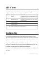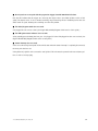
1
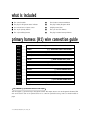
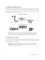
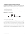
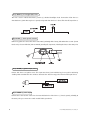
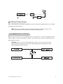
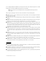
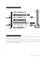
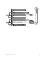
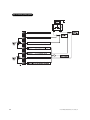
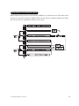
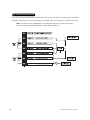
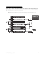
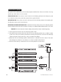
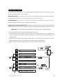
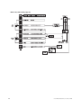
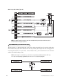
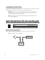
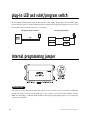
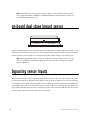
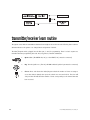
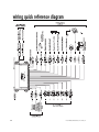
Model 2300
Installation Guide
© 2003 Directed Electronics, Inc. Vista, CA N2300 7-03
table of contents
What Is Included . . . . . . . . . . . . . . . . . . . . . . 2
feature descriptions . . . . . . . . . . . . . . . . . . . 28
Primary Harness (H1) Wire Connection Guide . . 4
nuisance prevention circuitry™ . . . . . . . . . . . 29
Door Lock Harness (H2) Wire Connection Guide . . 8
Identifying the Door Lock System . . . . . . . . . 8
At the Switch. . . . . . . . . . . . . . . . . . . . . . . 9
Type A Door Locks: Positive-Triggered,
Relay Driven Systems. . . . . . . . . . . . . . . . . 10
Type B Door Locks: Negative-Triggered,
Relay Driven Systems (Type B) . . . . . . . . . . 11
Type C Door Locks: Reversing Polarity Systems . 12
Type D Door Locks:
table of zones . . . . . . . . . . . . . . . . . . . . . . . 30
primary harness (H1) wire connection guide . . 3
door lock harness (H2) wire connection guide . 8
identifying the door lock system. . . . . . . . . . 8
at the switch . . . . . . . . . . . . . . . . . . . . . . . 9
type A: positive-triggered, relay-driven system .
. . . . . . . . . . . . . . . . . . . . . . . . . . . . . . . 10
type B: negative-triggered, relay-driven system
. . . . . . . . . . . . . . . . . . . . . . . . . . . . . . . 10
type C: reversing polarity system . . . . . . . . 12
type D: adding one or more after-market actuators . . . . . . . . . . . . . . . . . . . . . . . . . . . . 13
type E: electrically-activated vacuum. . . . . . 14
type F: one-wire system (cut to lock, ground to
unlock) . . . . . . . . . . . . . . . . . . . . . . . . . . 15
type G: positive (+) multiplex. . . . . . . . . . . 16
type H: negative (-) multiplex . . . . . . . . . . 17
plug-in LED and valet/program switch . . . . . . 22
internal programming jumper . . . . . . . . . . . . 22
light flash jumper . . . . . . . . . . . . . . . . . . . 22
on-board dual stage impact sensor . . . . . . . . 23
bypassing sensor inputs . . . . . . . . . . . . . . . . 23
transmitter/receiver learn routine . . . . . . . . . 24
transmitter configuration . . . . . . . . . . . . . . . 26
system features learn routine . . . . . . . . . . . . 26
features menu . . . . . . . . . . . . . . . . . . . . . . . 28
troubleshooting . . . . . . . . . . . . . . . . . . . . . . 30
wiring quick reference diagram . . . . . . . . . . . 32
Adding One or More
After-Market Actuators. . . . . . . . . . . . . . . . 13
Type E Door Locks: Electrically Activated . . . . .
Vacuum . . . . . . . . . . . . . . . . . . . . . . . . . . 14
Type F Door Locks: One-Wire System . . . . . . 15
Type G Door Locks: Positive (+) Multiplex. . . 16
Type H Door Locks: Negative (-) Multiplex . . 17
Auxiliary Harness (H3) Wire Connection Guide . 18
Starter Interrupt Harness (H4)
Wire Connection Guide . . . . . . . . . . . . . . . . . . 20
Plug-In LED and Valet/Program Switch . . . . . . 21
Internal Programming Jumper . . . . . . . . . . . . 21
On-Board Dual Stage Zone 2 Impact Sensor. . . 22
Bypassing Sensor Inputs . . . . . . . . . . . . . . . . 22
Transmitter/Receiver Remote Control
Code Learning . . . . . . . . . . . . . . . . . . . . . . . 23
Transmitter Configuration . . . . . . . . . . . . . . . 24
Operating Settings Remote Control
Code Learning . . . . . . . . . . . . . . . . . . . . . . . 25
Features Menu . . . . . . . . . . . . . . . . . . . . . . . 26
Feature Descriptions . . . . . . . . . . . . . . . . . . . 27
Nuisance Prevention Circuitry® . . . . . . . . . . . . 28
Table of Zones . . . . . . . . . . . . . . . . . . . . . . . 28
Troubleshooting . . . . . . . . . . . . . . . . . . . . . . 29
Wiring Quick Reference Guide . . . . . . . . . . . . 30
Avital®, Bitwriter™, Stealth Coding Technology™, Doubleguard®, ESP™, FailSafe®, Ghost Switch™, Learn
Routine™, Nite-Lite®, Nuisance Prevention Circuitry®, NPC®, Revenger®, Silent Mode™, Soft Chirp®,
Stinger®, Valet®, Vehicle Recovery System®, VRS®, and Warn Away® are all Trademarks or Registered
Trademarks of Directed Electronics, Inc.
2
© 2001 Directed Electronics, Inc. Vista, CA
what is included
■ The control module
■
Two 4-button remote transmitters
■ The plug-in LED system status indicator
■
The plug-in Valet®/Program switch
■ An on-board zone 2 impact sensor
■
A high-powered siren
■ The 12-pin primary harness
■
The 7-pin door lock harness
■ The 3-pin auxiliary harness
■
The plug-in starter interrupt harness
primary harness (H1) wire connection guide
H1/1
H1/2
H1/3
H1/4
H1/5
H1/6
H1/7
H1/8
H1/9
H1/10
H1/11
H1/12
______
______
______
______
______
______
______
______
______
______
______
______
ORANGE
(-) 500 mA GROUND-WHEN-ARMED OUTPUT
WHITE
(+/-) SELECTABLE LIGHT FLASH OUTPUT
WHITE/BLUE
BLACK/WHITE
(-) 200 mA CHANNEL 3 VALIDITY OUTPUT
OUTPUT OF INTERIOR LIGHT ILLUMINATION RELAY #30
GREEN
BLUE
(-) DOOR TRIGGER INPUT, ZONE 3
(-) MULTIPLEX TRIGGER INPUT, ZONE 1
VIOLET
(+) DOOR TRIGGER INPUT, ZONE 3
BLACK
(-) CHASSIS GROUND INPUT
YELLOW
(+) IGNITION INPUT, ZONE 5
BROWN
(+) SIREN OUTPUT
RED
RED/WHITE
(+)12V CONSTANT POWER INPUT
(-) 200 mA CHANNEL 2 VALIDITY OUTPUT
H1/1 ORANGE (-) ground-when-armed 500 mA output
This wire supplies (-) ground as long as the system is armed. This output ceases as soon as the system is disarmed. This
wire can be used to turn on an optional sensor or to control an optional accessory, such as a window module or
pager.
© 2003 Directed Electronics, Inc. Vista, CA
3
H1/2 WHITE (+/-) selectable light flash output
As shipped, this wire should be connected to the (+) parking light wire. If the light flash polarity jumper inside
the control module is moved to the opposite position (see Internal Programming Jumper section of this guide),
this wire supplies a (-) 200 mA output. This is suitable for driving (-) light control wires in Toyota, Lexus, BMW,
some Mitsubishi, some Mazda, and other model cars.
(+) Positive Light Flash Output
(-) Negative Light Flash Output
NOTE: For parking light circuits that draw 10 amps or more, the internal jumper must be switched
to a (-) light flash output. (See the Internal Programming Jumper section of this guide.) P/N 8617
or a standard automotive SPDT relay must be used on the H1/2 light flash output harness wire.
H1/3 WHITE/BLUE (-) channel 3 output
This wire provides a (-) 200 mA output whenever the transmitter code controlling Channel 3 is received. This
output will continue as long as that transmission is received. Use for options such as 551T Valet® Start system,
529T or 530T power window controllers, etc.
IMPORTANT! Never use this wire to drive anything except a relay or a low-current input! The transistorized output can only provide 200 mA of current, and connecting directly to a solenoid, motor,
or other high-current device will cause it to fail.
4
© 2001 Directed Electronics, Inc. Vista, CA
H1/4 BLACK/WHITE high current output from on-board interior light illumination relay
Connect this wire directly to the domelight circuit in the vehicle. The on-board relay will drive circuits up
to 20 amperes. The polarity of this output is determined by the connection of the H2/A input wire in the
Auxiliary Harness.
NOTE: If the H2/A input wire is not connected, there will be no output on this wire.
H1/5 GREEN (-) door trigger input, zone 3
Most vehicles use negative door trigger circuits. Connect the green wire to a wire which shows ground when any
door is opened. In vehicles with factory delays on the domelight circuit, there is usually a wire that is unaffected
by the delay circuitry. This wire will report Zone 3.
H1/6 BLUE (-) multiplex trigger input, zone 1
This wire will respond to a negative input with an instant trigger. Inputs shorter than 0.8 seconds will trigger
the Warn Away response, while triggers longer than 0.8 seconds will instantly trigger the full alarm cycle. This
wire is ideal for hood and trunk pins and will report on Zone 1. This wire can also be used with Directed
Electronic’s 506T Glass Breakage Sensor, as well as other Directed Electronic’s single stage sensors. The H1/6 BLUE
multiplex trigger wire can be used to shunt sensors during operation, using the auxiliary channels. When any of
the auxiliary channels are transmitted, the H1/6 BLUE wire monitors for a ground. If ground is detected within
5 seconds of transmission, the sensors and the multiplex trigger input on the BLUE wire will be shunted until 5
seconds after the ground is removed. This allows the customer to access the trunk, remote start the vehicle, or
roll the windows down without first disarming the alarm. (See Bypassing Sensor Inputs section of this guide.)
© 2003 Directed Electronics, Inc. Vista, CA
5
H1/7 VIOLET (+) door trigger input, zone 3
This wire is used in vehicles that have a positive (+) switched domelight circuit. Connect the violet wire to a
wire that shows (+)12V when any door is opened, and ground when the door is closed. This wire will report Zone 3.
H1/8 BLACK (-) chassis ground connection
Remove any paint and connect this wire to bare metal, preferably with a factory bolt rather than a screw. (Screws
tend to strip or loosen with time.) We recommend grounding all components, including the siren, to the same point.
H1/9 YELLOW (+) ignition input, zone 5
Connect this wire to an ignition source. This input must show (+)12V with the key in run position and during
cranking. Make sure that this wire cannot be shorted to the chassis at any point. This wire will report Zone 5.
H1/10 BROWN (+) siren output
Connect this to the red wire of the siren. Connect the black wire of the siren to (-) chassis ground, preferably at
the same point you connect the control module’s black ground wire.
6
© 2001 Directed Electronics, Inc. Vista, CA
H1/11 RED (+)12V constant power input
Before connecting this wire, remove the supplied fuse. Connect to the positive battery terminal or the constant
12V supply to the ignition switch.
NOTE: Always use a fuse within 12 inches of the point you obtain (+)12V power. Do not use the
15A fuse in the harness for this purpose. This fuse protects the module itself.
H1/12 RED/WHITE channel 2, (-) 200mA output
When the system receives the code controlling Channel 2, for longer than 1.5 seconds, the red/white wire will
supply an output as long as the transmission continues. This is often used to operate a trunk/hatch release or
other relay-driven function.
IMPORTANT! Never use this wire to drive anything but a relay or a low-current input! The transistorized output can only supply 200 mA of current. Connecting directly to a solenoid, motor, or other
high-current device will cause it to fail.
© 2003 Directed Electronics, Inc. Vista, CA
7
door lock harness (H2) wire connection guide
H2/A
H2/B
H2/C
H2/D
H2/E
H2/F
H2/G
______
______
______
______
______
______
______
BLACK/WHITE
INPUT TO ON-BOARD INTERIOR LIGHT ILLUMINATION RELAY #87
WHITE/BLACK
UNLOCK RELAY, NORMALLY CLOSED
GREEN/BLACK
UNLOCK RELAY, COMMON
VIOLET/BLACK*
UNLOCK RELAY, NORMALLY OPEN
BROWN/BLACK
LOCK RELAY, NORMALLY CLOSED
BLUE/BLACK
VIOLET*
LOCK RELAY, COMMON
LOCK RELAY, NORMALLY OPEN
*VIOLET and VIOLET/BLACK wires are common at the fuseholder.
The system has door lock relays on-board, and can directly interface with most electric power door lock systems
drawing 30 amps or less. It can also drive aftermarket actuators directly. (Some vehicles require that an aftermarket actuator be added to the driver’s door to allow system control, see Type D wiring section).
H2/A BLACK/WHITE input to on-board interior light illumination relay #87
This wire determines what the output polarity of H1/4 will be. If the door pin circuit is negative, connect to
chassis ground. If the door circuit is positive, connect to a fused 12V source.
IMPORTANT! The H2/A wire is not required for wiring the door locks. Depending on the type of door
lock system, there may be additional wires in the Door Lock Harness (H2) that are not required
used in wiring the door locks.
H2/B - H2/G power door lock wires
The system has door lock relays on-board, and can directly interface with most electric power door lock systems
drawing 20 amps or less.
identifying the door lock system
The easiest way to determine which type of door lock system you are working with is to remove the master
locking switch itself, which is usually on the driver’s door or on the center console. Once you have determined
which type of factory door lock circuit you are working with, and the color codes of the switch wires to be used,
8
© 2001 Directed Electronics, Inc. Vista, CA
you can usually simplify the installation by locating the same wires in the vehicle’s kick panel. If no central
locking switch is found, the installation may require a door lock actuator.
NOTE: Always retest the wires in the kick panel to be sure they function the same way as the wires
on the switch.
There are eight common types of door lock circuits (some vehicles use more unusual systems):
■ Type A: Three-wire (+) pulse controlling factory lock relays. Most GM, some Ford and Chrysler, 1995 Saturn,
some new VW, newer BMW.
■ Type B: Three-wire (-) pulse controlling factory lock relays. Most Asian vehicles, early Saturn, some BMW and
Porsche.
■ Type C: Direct-wired reversing-polarity switches. The switches are wired directly to the motors. This type of
system has no factory relays. Most Fords, many GM two-doors cars and trucks, many Chryslers.
■ Type D: Adding one or more aftermarket actuators. These include slave systems without an actuator in the
driver’s door, but with factory actuators in all the other doors. Type D also includes cars without power locks,
which will have actuators added. All Saabs before 1994, all Volvo except 850i, all Subaru, most Isuzu, and
many Mazdas. Some mid-eighties Nissans, pre-1985 Mercedes-Benz and Audi.
■ Type E: Electrically-activated vacuum systems. The vehicle must have a vacuum actuator in each door. Make
sure that locking the doors from the driver's or passenger side using the key activates all the actuators in
the vehicle. This requires a slight modification to the door lock harness. Mercedes-Benz and Audi 1985 and
newer.
■ Type F: One-wire system - cut to lock, ground to unlock. This system is found in late-model Nissan Sentras,
some Nissan 240SX, and Nissan 300ZX 1992 and later. It is also found in older Mitsubishis, and some early
Mazda MPV’s.
■ Type G: Positive (+) multiplex. This system is most commonly found in Ford, Mazda, Chrysler and GM vehicles. The door lock switch or door key cylinder may contain either one or two resistors.
■ Type H: Negative (-) multiplex. The system is most commonly found in Ford, Mazda, Chrysler and GM vehicles. The door lock switch or door key cylinder may contain either one or two resistors.
at the switch
■ Three-wire switches will have either a constant ground input or a constant (+)12V input, along with the
pulsed lock and unlock outputs to the factory relays.
■ Many BMW’s and VW’s have no external switch. The switches are inside the actuator, and instead of pulsing,
the proper wires will flip-flop from (+)12V to (-) ground as the door locks are operated.
■ Direct-wired switches will have a (+)12V constant input and one or two (-) ground inputs, along with two
output leads going directly to the lock motors.
© 2003 Directed Electronics, Inc. Vista, CA
9
type A: positive-triggered, relay-driven system
type B: negative-triggered, relay-driven system
This system is common in many Toyota, Nissan, Honda, and Saturn models, as well as Fords with the keylessentry system (some other Fords also use Type B).
The switch will have three wires on it, and one wire will test ground all the time. One wire will pulse (-) when
the switch locks the doors, and the other wire will pulse (-) when the switch unlocks the doors. This type of
system is difficult to mistake for any other type.
10
© 2001 Directed Electronics, Inc. Vista, CA
© 2003 Directed Electronics, Inc. Vista, CA
11
type C: reversing polarity system
12
© 2001 Directed Electronics, Inc. Vista, CA
type D: adding one or more after-market actuators
Vehicles without factory power door locks require the installation of one actuator per door. This requires mounting the door lock actuator inside the door. Other vehicles may only require one actuator installed in the driver's
door if all door locks are operated when the driver's lock is used.
© 2003 Directed Electronics, Inc. Vista, CA
13
type E: electrically-activated vacuum
This system is found in Mercedes-Benz and Audi 1985 and newer. The door locks are controlled by an electrically
activated vacuum pump. The control wire will show (+)12V when doors are unlocked and (-) ground when locked.
NOTE: The system must be programmed for 3.5-second door lock pulses, and the violet jumper
between the #87 lock terminal and the #87 unlock terminal must be cut.
14
© 2001 Directed Electronics, Inc. Vista, CA
type F: one-wire system (cut to lock, ground to unlock)
This type of door lock system usually requires a negative pulse to unlock, and cutting the wire to lock the door.
(With some vehicles, these are reversed.) It is found in the late-model Nissan Sentras, some Nissan 240SX, Nissan
300ZX 1992 and later. It is also found in some Mazda MPV's.
NOTE: The violet jumper between the #87 lock terminal and the #87 unlock terminal must be cut.
© 2003 Directed Electronics, Inc. Vista, CA
15
type G: positive (+) multiplex
This system is most commonly found in Ford, Mazda, Chrysler and GM vehicles. The door lock switch or door key
cylinder may contain either one or two resistors.
SINGLE-RESISTOR TYPE: If one resistor is used in the door lock switch/key cylinder, the wire will pulse (+)12V
in one direction and less than (+)12V when operated in the opposite direction.
TWO-RESISTOR TYPE: If two resistors are used in the factory door lock switch/key cylinder, the switch/key cylinder will read less than (+)12V in both directions.
DETERMINING THE PROPER RESISTOR VALUES: To determine the resistor values, the door lock switch/key cylinder
must be isolated from the factory door lock system. For testing, use a calibrated digital multimeter that is set to ohms.
IMPORTANT: To ensure an accurate resistance reading, do not touch the resistor or leads during testing.
1. Cut the output wire from the door lock switch/key cylinder in half.
2. Test with the meter from the switch side of the cut door lock switch/key cylinder wire to a reliable constant
(+)12V source. Some good constant (+)12V references are the power input source to the door lock switch/key
cylinder, the ignition switch power wire, or the (+) terminal of the battery.
3. Operate the door lock switch/key cylinder in both directions to determine the resistor values. If the multimeter displays zero resistance in one direction, no resistor is needed for that direction.
4. Once the resistor value(s) is determined, refer to the wiring diagram for proper wiring.
16
© 2001 Directed Electronics, Inc. Vista, CA
type H: negative (-) multiplex
The system is most commonly found in Ford, Mazda, Chrysler and GM vehicles. The door lock switch or door key
cylinder may contain either one or two resistors.
SINGLE-RESISTOR TYPE: If one resistor is used in the door lock switch/key cylinder, the wire will pulse ground
in one direction and resistance to ground when operated in the opposite direction.
TWO-RESISTOR TYPE: If two resistors are used in the factory door lock switch/key cylinder, the door lock
switch/key cylinder will read resistance to ground in both directions.
DETERMINING THE PROPER RESISTOR VALUES: To determine the resistor values, the door lock switch/key cylinder
must be isolated from the factory door lock system. For testing, use a calibrated digital multimeter that is set to ohms.
IMPORTANT: To ensure an accurate resistance reading, do not touch the resistor or leads during testing.
1. Cut the output wire from the door lock switch/key cylinder in half.
2. Test with the meter from the switch side of the cut door lock switch/key cylinder wire to a reliable ground
source. Some good ground references are the ground input source to the door lock switch/key cylinder or the
battery ground.
3. Operate the door lock switch/key cylinder in both directions to determine the resistor values. If the multimeter displays zero resistance in one direction, no resistor is needed for that direction.
4. Once the resistor value(s) is determined, refer to the wiring diagram for proper wiring.
© 2003 Directed Electronics, Inc. Vista, CA
17
auxiliary harness (H3) wire connection guide
H3/1
H3/2
H3/3
______
______
______
BLUE
(-) SECOND UNLOCK
BROWN/BLACK
(-) 200 mA HORN HONK OUTPUT
VIOLET/BLACK
(-) 200 mA CHANNEL 4 OUTPUT
H3/1 BLUE (-) 200mA second unlock output
This output is used for progressive door unlock. A progressive unlock system unlocks the driver's door when the
unlock (disarm) button is pressed and unlocks the passenger doors if the unlock (disarm) button is pressed again
within 15 seconds after unlocking the driver's door. The BLUE wire outputs a low current (-) pulse on the second
press of the unlock button of the transmitter. This negative unlock output is used to unlock the passenger doors.
NOTE: The second unlock output feature is not available if the double pulse unlock feature is turned on.
IMPORTANT! The H2/A wire is not required for wiring the door locks. Depending on the type of door
lock system, there may be additional wires in the Door Lock Harness (H2) that are not required
used in wiring the door locks.
18
© 2001 Directed Electronics, Inc. Vista, CA
Driver’s Door Unlock Only (Type A):
19
© 2001 Directed Electronics, Inc. Vista, CA
19
Driver’s Door Unlock Only (Type B):
NOTE: The VIOLET jumper between the #87 lock terminal and the #87 unlock terminal must be cut
and connected to the proper polarities.
H3/2 BROWN/BLACK (-) 200 mA horn honk output
This wire supplies a (-) 200 mA output that can be used to honk the vehicle’s horn. It provides a single pulse
when armed and two pulses when disarmed. This wire also provides pulsed output when the security system is
in the triggered sequence or in panic mode. In most vehicle’s with (-) horn circuits this wire can control the
vehicle’s horn without adding a relay.
NOTE: If this output is used to drive a (+) horn circuit, an optional standard automotive SPDT relay
or a relay assembly package (p/n 8617) must be used. See the following diagram.
20
© 2001 Directed Electronics, Inc. Vista, CA
H3/3 VIOLET/BLACK (-) 200 mA channel 4 output
This wire supply a (-)200mA output whenever the button(s) controlling channel four is pressed and will continue
until the button(s) is released. This output can be used to control optional accessories.
IMPORTANT! Never use this wire to drive anything but a relay or a low-current input! This
transistorized output can only supply (-)200 mA, and connecting directly to a solenoid, motor, or
other high-current device will cause the module to fail.
NOTE: Many of the options that can be operated with this output require the addition of the relay
accessory package (p/n 8617).
starter interrupt harness (H4) wire connection guide
H4/1
H4/2
______
______
BLACK
STARTER INTERRUPT INPUT
BLACK
STARTER INTERRUPT OUTPUT
H4/1 and H4/2 BLACK starter interrupt wires
Use one of these wire as a starter interrupt input and the other as a starter interrupt output wire.
NOTE: These two black wires are interchangeable.
21
© 2001 Directed Electronics, Inc. Vista, CA
plug-in LED and valet/program switch
The LED and the Valet/Program switch both plug into the control module. The LED system status indicator plugs
into the white two-pin port, while the Valet®/Program switch should be plugged into the blue two-pin port. The
LED and Valet®/Program switch each fit into 9/32-inch holes.
LED System Status Indicator
Valet®/Program Switch
DIA-41
internal programming jumper
light flash jumper
This jumper is used to determine the light flash output. In the (+) position, the on-board relay is enabled and
the unit will output (+)12V on the H1/2 WHITE wire. In the (-) position, the on-board relay is disabled. The H1/2
WHITE wire will supply a (-) 200 mA output suitable for driving factory parking light relays. To access the jumper,
open the control module.
22
© 2001 Directed Electronics, Inc. Vista, CA
NOTE: For parking light circuits that draw 10 amps or more, the internal jumper must be switched
to a (-) light flash output. P/N 8617 or a standard automotive SPDT relay must be used on the
H1/2 light flash output harness wire.
on-board dual stage impact sensor
There is a dual-stage impact sensor inside the control unit. Adjustments are made via the rotary control as indicated above. Since the impact sensor does not work well when mounted firmly to metal, we recommend against
screwing down the control module. We recommend mounting the control module to a large wiring loom.
NOTE: When adjusting the sensor, it must be mounted in the same location where it will be
after the installation is completed. Adjusting the sensor and then relocating the module
requires readjustment.
bypassing sensor inputs
There are times when you need to temporarily bypass all sensor inputs to the unit, such as when remote starting the vehicle. Anytime an auxiliary channel output is used, all inputs are bypassed for 5 seconds. During the
5 second bypass period, ground can be supplied to the H1/6 BLUE wire without triggering the unit. When the 5
second bypass period ends, if the unit detects ground on the H1/6 BLUE wire, all trigger inputs except the door
trigger input will remain bypassed until 5 seconds after ground is removed from the BLUE wire. This can be done
using the status output of the remote start unit as shown below:
23
© 2001 Directed Electronics, Inc. Vista, CA © ©
20
transmitter/receiver learn routine
The system comes with two transmitters that have been taught to the receiver. Use the following learn routine to
add transmitters to the system or to change button assignments if desired.
The Valet®/Program switch, plugged into the blue port, is used for programming. There is a basic sequence to
remember whenever programming this unit: Door, Key, Choose, Transmit and Release.
1.
Open a door. (The GREEN wire, H1/5, or the VIOLET, H1/7 must be connected.)
2.
Key. Turn the ignition on. (The H1/9 YELLOW switched ignition input must be connected.)
3.
Choose. Press and release the Valet®/Program switch the number of times necessary to
access the desired channel, then press the switch once more and Hold it. The siren will
chirp and the LED will blink the number of times corresponding to the channel that has
been accessed.
24
© 2001 Directed Electronics, Inc. Vista, CA
CHANNEL
NUMBER
PRESS AND RELEASE
THE VALET/PROGRAM SWITCH
TO PROGRAM FUNCTION
1
One Time
Arm/Disarm/Panic
2
Two Times
Channel 2
3
Three Times
Channel 3
4
Four Times
Channel 4
5
Five Times
Arm Only
6
Six Times
Disarm Only
7
Seven Times
Panic Only
8
Eight Times
Auto-learn*
9
Nine Times
Delete all transmitters**
*NOTE: See Transmitter Configuration section of this guide for a description of Auto-learn transmitter programming.
**NOTE: If any button from a known transmitter is programmed to Channel 9, all transmitters
will be erased from memory and the system will revert to the default feature settings. (See
Features Menu section of this guide.)
4.
Transmit. While HOLDING the Valet®/Program switch, press the transmitter button that you
wish to assign to that channel. The unit will chirp indicating successful programming.
5.
Release. Once the code is learned, the Valet®/Program switch can be released.
You can advance from one channel to another by releasing the Valet® /Program switch and tapping it to advance
channels and then HOLDING it. For example, if you want to program Channel Three after programming Channel
One, release the Valet®/Program switch. Press it twice and release it to advance to Channel Three. Then press it once
more and HOLD it. The siren will chirp three times to confirm it is ready to receive the code from the transmitter.
One long chirp will indicate that Code Learning has been exited if any of the following occurs:
■ Ignition is turned off.
■ The doors are closed.
■ Valet®/Program switch is pressed too many times.
■ More than 15 seconds elapses between steps.
© 2003 Directed Electronics, Inc. Vista, CA
25
transmitter configuration
The standard 4-button transmitters can be programmed in one step by using the Auto-learn function. When programmed for Standard Configuration, the 4-button transmitter buttons are assigned to the following functions:
Button.......................................................operates...............................................Arm
Button .....................................................operates...............................................Disarm
Button .....................................................operates...............................................Channel Two
Button .....................................................operates...............................................Panic
and
Buttons.....................................operate ................................................Channel Three
and
Buttons.....................................operate ................................................Channel Four
system features learn routine
Many of the features of this unit are programmable. They can be changed whenever necessary through this learn
routine. The Valet®/Program switch, plugged into the blue port, is used together with a programmed transmitter
to change the settings.
To enter the feature learn routine:
1.
Open a door. (The GREEN wire, H1/5, or the VIOLET, H1/7 must be connected.)
2.
Ignition. Turn the ignition on, then back off. (The H1/9 YELLOW switched ignition input
must be connected.)
2.
Choose. Within 10 seconds, press and release the Valet®/Program switch the number of
times corresponding to the feature number you want to program (see the Features Menu
section of this guide). Then press the switch once more and hold it.
The LED will flash and the siren will chirp to indicate which feature you have accessed.
26
© 2001 Directed Electronics, Inc. Vista, CA
4.
Transmit. While HOLDING the Valet®/Program switch, you can select the desired features
setting using the remote transmitter. Pressing the lock icon transmitter button while
HOLDING down the Valet/Program switch will program the feature to the LED ON (default)
setting. The siren will chirp once. Pressing the unlock icon transmitter button while
HOLDING down the Valet/Program switch will change the setting to the LED OFF setting.
The siren will chirp twice.
5.
Release. Release the Valet®/Program switch.
To access another feature:
You can advance from feature to feature by pressing and releasing the Valet®/Program switch the number of times
necessary to get from the feature you just programmed to the feature you wish to access. For example, if you
just programmed Feature 1 and you want to program Feature 2:
1. Release the Valet®/Program switch.
2. Press and release the Valet/Program switch once to advance from Feature 1 to Feature 2.
3. Press the Valet®/Program switch once more and HOLD it.
4. The siren will chirp two times to confirm that you have accessed Feature 2.
To exit the Code Learning, do one of the following:
■ The doors are closed.
■ Turn the ignition on.
■ No activity for longer than 15 seconds.
■ Press the Valet®/Program switch too many times.
© 2003 Directed Electronics, Inc. Vista, CA
27
features menu
FEATURE
NUMBER
DEFAULT LED ON SETTINGS
LED OFF SETTINGS
(PRESS LOCK ICON TRANSMITTER BUTTON) (PRESS UNLOCK ICON TRANSMITTER BUTTON)
1
Active Arming
Passive Arming
2
Confirmation Chirps ON
Confirmation Chirps OFF
3
Ignition Controlled Door Lock/Unlock ON Ignition Controlled Door Lock/Unlock OFF
4
Active Locking
Passive Locking
5
0.8-second Door Lock Pulse Duration
3.5-second Door Lock Pulse Duration
6
Double Pulse Unlock OFF
Double Pulse Unlock ON
7
Stealth Coding Technology ON
Stealth Coding™ Technology OFF
™
NOTE: Factory defaults are indicated in bold type.
feature descriptions
1 ACTIVE/PASSIVE ARMING: When active arming is selected, the system will only arm when the transmitter is
used. When set to passive, the system will arm automatically 30 seconds after the last protected entry is closed.
Passive arming is indicated by the rapid flashing of the LED when the last protected entry point is closed.
2 CONFIRMATION CHIRPS ON/OFF: This feature controls the chirps that confirm the arming and disarming of
the system.
3 IGNITION-CONTROLLED DOOR LOCK/UNLOCK ON/OFF: When turned on, the doors will lock three seconds
after the ignition is turned on and unlock when the ignition is turned off. If the ignition key is turned on while
the vehicle door(s) are open, the door(s) will not lock.
4 ACTIVE/PASSIVE LOCKING: If passive arming is selected in Feature 1, then the system can be programmed
to either lock the doors when passive arming occurs, or only lock the doors when the system is armed with the
transmitter. Active locking means the system will not lock the doors when it passively arms. Passive locking
means that the system will lock the doors when it passively arms.
5 DOOR LOCK PULSE DURATION: Some European vehicles, such as Mercedes-Benz and Audi, require longer lock
and unlock pulses to operate the vacuum pump. Programming the system to provide 3.5 second pulses will
28
© 2001 Directed Electronics, Inc. Vista, CA
accommodate door lock interface in these vehicles. The default setting is 0.8 second door lock pulses. See
Mercedes-Benz and Audi - 1985 and Newer (Type E Door Locks section) diagram.
6 DOUBLE PULSE UNLOCK OFF/ON: Some vehicles require two pulses on a single wire to unlock the doors. When
the double pulse unlock feature is turned on, the H2/2 BLUE/BLACK wire will supply two pulses instead of a
single pulse. This makes it possible to directly interface with double pulse vehicles without any extra parts.
NOTE: The second unlock output feature (H3/1 BLUE wire) is not available if the double pulse
unlock feature is turned on.
7 STEALTH CODING™ TECHNOLOGY ON/OFF: This system features Stealth Coding™ Technology as an option.
Stealth Coding™ Technology is a feature that uses a mathematical formula to change the system’s code each time
the transmitter and receiver communicate. This makes the group of bits or "word" from the transmitter very long.
The longer the word is, the easier it is to block its transmission to the unit. Disabling the Stealth Coding™
Technology feature lets the receiver ignore the Stealth Coding™ Technology part of the transmitted word. As a
result, the unit may have better range with Stealth Coding™ Technology off.
nuisance prevention circuitry™
NPC™ requires that you change the way you test the system, as NPC™ will bypass an input zone for 60 minutes.
If the system “sees” the same zone trigger three times AND the triggers are spaced less than an hour apart, the
system will bypass that input zone for 60 minutes. If that zone does not attempt to trigger the system during
the 60-minute bypass period, the zone’s monitoring will begin again at the end of the hour. If it does attempt
to trigger while bypassed, the 60-minute bypass starts over again.
Disarming and rearming the system does not reset NPC™. The only way to reset NPC™ is for the 60 minutes to
pass, without a trigger, or for the ignition to be turned on. This allows the system to be repeatedly triggered,
disarmed and rearmed, and still allow NPC™ to bypass a faulty zone.
When disarming the system, 5 chirps indicate NPC is activated. The LED will report the zone that has been
bypassed. (See Table of Zones section of this guide.)
© 2003 Directed Electronics, Inc. Vista, CA
29
table of zones
When using the Diagnostic functions, use the Table of Zones to see which input has triggered the system. It is
also helpful in deciding which input to use when connecting optional sensors and switches.
ZONE NO.
TRIGGER TYPE
INPUT DESCRIPTION
1
Multiplex
H1/6 BLUE wire. Connects to optional hood/trunk pins or
an optional sensor. Inputs longer than 0.8 seconds will
instantly trigger the full alarm sequence and report Zone 1.
2
On-board impact sensor
Second-stage of on-board impact sensor (heavy impacts
from impact sensor).
3
Two-stage, progresses from
warning to full alarm
Door switch circuit. H1/5 GREEN or H1/7 VIOLET.
5
Two-stage, progresses from
warning to full alarm
Ignition. H1/9 YELLOW.
NOTE: The Warn-away response does not report on the LED.
troubleshooting
■ Door input does not immediately trigger full alarm. Instead, first I hear chirps for 3 seconds:
That's how the progressive two-stage door input works! This is a feature of this system. This is an instant trigger,
remember, since even if the door is instantly re-closed, the progression from chirps to constant siren will continue.
■ Closing the door triggers the system, but opening the door does not:
Have you correctly identified the type of door switch system? This often happens when the wrong door input has
been used. (See H1/5 GREEN Door Trigger Input, Primary Harness Wire Connection Guide section of this guide.)
■ System will not passively arm until it is remotely armed and then disarmed:
Are the door inputs connected? Is the H1/6 blue wire connected to the door trigger wire in the vehicle? Either
the H1/5 green or the H1/7 violet should be used instead. (See Primary Harness Wire Connection Guide section
of this guide.)
30
© 2003 Directed Electronics, Inc. Vista, CA
■ Door input does not respond with the progressive trigger, but with immediate full alarm:
Does the LED indicate that the trigger was caused by the impact sensor? (See Table of Zones section of this
guide.) The impact sensor, if set to extreme sensitivity, may be detecting the door unlatching before the door
switch sends its signal. Reducing the sensitivity can solve this problem.
■ The Valet®/Program switch does not work:
Is it plugged into the correct socket? (See Plug-In LED and Valet/Program Switch section of this guide.)
■ The LED system status indicator does not work:
You've probably guessed already, but here goes: is it plugged in? Is the LED plugged into the correct socket? (See
Plug-In LED and Valet/Program Switch section of this guide.)
■ Starter interrupt does not work:
Is the correct wire being interrupted? If the vehicle starts when the starter interrupt is completely disconnected,
the wrong wire has been cut.
Is the yellow H1/9 ignition wire connected to true ignition? This wire must be powered in the run and start positions in order to work properly.
© 2003 Directed Electronics, Inc. Vista, CA
31
wiring quick reference diagram
32
© 2001 Directed Electronics, Inc. Vista, CA
© 2003 Directed Electronics, Inc. Vista, CA
33