1
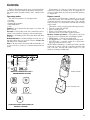
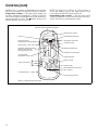
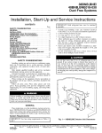
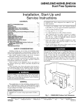
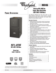
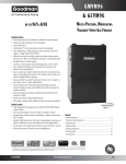
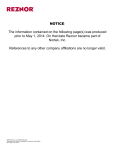
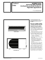
Product
Data
38/40BN Series
Duct-Free Split Systems
Cooling Only and Heat Pumps for
High-Wall Applications
11/2 to 3 Nominal Tons
The Ideal Complement to Your
Ducted System When It Is Impractical
or Prohibitively Expensive to Use
Ductwork
Features/Benefits
An inexpensive and creative
solution to design problems
INDOOR UNIT
OUTDOOR UNIT
Copyright 2004 Carrier Corporation
The 38/40BN series duct-free split systems are a matched combination of an
outdoor condensing unit and an indoor
fan coil units connected only by refrigerant tubing and wires.
The fan coil is mounted on the wall,
near the ceiling. This selection of fan
coils permits inexpensive and creative
solutions to design problems such as:
• add-ons to current space (an office
or family room addition)
• special space requirements (a computer room)
• when changes in the load cannot be
handled by the existing system
• when adding air conditioning to
spaces that are heated by hydronic
or electric heat and have no
ductwork
• historical renovations or any application where preserving the look of
the original structure is essential
These compact indoor fan coil units
take up very little space in the room
and do not obstruct windows. The fan
coils are attractively styled to blend
with most room decors. Advanced system components incorporate innovative technology to provide reliable cooling performance at low sound levels.
Form 38B/40B-1PD
The 38/40BN duct-free split systems offer the solution of choice. The
compressor is outdoors, linked by refrigerant lines to an indoor fan coil located directly in the room it will heat or
cool. These systems have minimal impact on the existing structure, and the
design and interior of the conditioned
space is not compromised by bulky
ductwork. Because of these features,
this duct-free split system can be installed in places where conventional
ducted cooling simply cannot go.
Low sound levels
When noise is a concern, the duct-free
split systems are the answer because
you do not have to worry about duct
design. There are no compressors
indoors, either in the conditioned
space or directly over it, and there is
none of the noise usually generated by
air being forced through ductwork. The
indoor units are whisper quiet. The
outdoor units operate at low sound levels, and are the perfect answer to
sound level ordinances.
When sound ordinances and proximity to neighbors demand quiet operation, the 38BN unit is the right
choice: The advanced, horizontal airflow design distributes air more evenly
over the coil. The coil also acts as an
extra sound-suppressing device
before the air is discharged at a very
low velocity.
Secure operation
If security is an issue, outdoor and
indoor units are connected only by
refrigerant piping and wiring to prevent intruders from crawling through
ductwork. In addition, since 38BN
units can be installed 6 in. away from
outside walls, coils are protected from
vandals and severe weather.
Fast installation
This compact duct-free split system
takes only a few hours to install, since
only wire and piping need to be run.
The fast and easy installation ensures
minimal disruption to customers in the
home or workplace. This is an added
advantage of the 38/40BN duct-free
split systems, especially in retrofit
situations.
Features like mounting brackets
make the unit very easy to install.
Simple servicing and
maintenance
Removing a panel on outdoor units
provides immediate access to the isolated compressor and control compartment, allowing a service technician
access to check unit operation without
a loss of condenser airflow. In addition,
the draw-thru design of the outdoor
section means that dirt accumulates on
the outside surface of the coil. Coils
can be cleaned quickly from the inside
using a pressure hose and detergent.
On all indoor units, service and
maintenance expense is reduced due
to easy-to-change cleanable filters. In
addition, these high wall systems have
extensive self-diagnostics to assist in
troubleshooting.
Built-in reliability
Duct-free split system indoor and outdoor units are designed to provide
years of trouble-free operation.
The high wall indoor units include
protection against freeze-up and high
discharge temperatures. All systems
include self-diagnostics to ensure
reliability.
The condensing units have many
safety features standard to ensure high
performance and lasting reliability under the most demanding situations. For
example, start capacitors and relays
assure dependable start-ups, especially
during low voltage conditions down to
187 v.
The totally enclosed condenser-fan
motor means greater reliability under
rain conditions, ensuring dependable
performance for many years.
Individual room comfort
Maximum comfort is provided because
each space can have individual set
points and may be controlled based on
actual usage. The air sweep feature
provided permits optimal room air mixing to eliminate hot and cold spots for
occupant comfort.
In addition, year-round comfort can
be provided with heat pumps.
Table of contents
Page
Features/Benefits . . . . . . . . . . . . . . . . . . . . . . . . . . . . . . . . . . . . . . . . . . 1-3
Model Number Nomenclature . . . . . . . . . . . . . . . . . . . . . . . . . . . . . . . . . . . 4
ARI Capacity Ratings . . . . . . . . . . . . . . . . . . . . . . . . . . . . . . . . . . . . . . . . . 5
Sound Ratings . . . . . . . . . . . . . . . . . . . . . . . . . . . . . . . . . . . . . . . . . . . . . . 5
Physical Data . . . . . . . . . . . . . . . . . . . . . . . . . . . . . . . . . . . . . . . . . . . . . 6,7
Base Unit Dimensions . . . . . . . . . . . . . . . . . . . . . . . . . . . . . . . . . . . . . . 8-11
Electrical Data . . . . . . . . . . . . . . . . . . . . . . . . . . . . . . . . . . . . . . . . . . . . . 12
Typical Piping and Wiring . . . . . . . . . . . . . . . . . . . . . . . . . . . . . . . . . . . . . 13
Application Data. . . . . . . . . . . . . . . . . . . . . . . . . . . . . . . . . . . . . . . . . . . . 14
Typical Wiring Schematics. . . . . . . . . . . . . . . . . . . . . . . . . . . . . . . . . . 15-20
Controls. . . . . . . . . . . . . . . . . . . . . . . . . . . . . . . . . . . . . . . . . . . . . . . 21,22
Guide Specifications — Indoor Unit . . . . . . . . . . . . . . . . . . . . . . . . . . . 23,24
Guide Specifications — Outdoor Unit . . . . . . . . . . . . . . . . . . . . . . . . . . 25,26
2
Features/Benefits (cont)
Economical operation
The duct-free split system design allows
individual room heating or cooling only
where required. There is no need to
run large supply-air fans or chilled
water pumps to handle a few spaces
with unique load patterns. In addition,
because air is moved only in the space
required, no energy is wasted moving
air through ducts.
Features like the rifled copper tube
with louvered aluminum plate fin coil
provide maximum heat transfer.
Lightweight, compact size
The small footprint of these units provides additional benefits. The exclusive
aero acoustics makes these units the
most compact in the industry. Because
they require minimal service and airflow clearances, condensing units can
be located virtually anywhere — on the
ground, roof, balcony, or under a deck.
The outdoor unit can be mounted
on any type or weight roof, and the indoor units take up little valuable, rentable space. Because they are duct-free,
not having to run large ductwork
leaves additional space to be rented or
utilized, making the building even more
profitable.
In addition, the small size makes
these units easily moveable. When
floor plans change, the units can be
quickly reinstalled.
Accessories
Easy-to-use controls
All systems are listed with ARI (Air
Conditioning & Refrigeration Institute),
UL (Underwriters’ Laboratories), and
CEC (California Energy Commission).
The microprocessor-based control in
the high-wall unit is easy to use, permitting easy changes for maximum
comfort. The microprocessor offers
the ultimate in comfort and efficiency.
All units automatically restart and
retain their memories after a power
failure, eliminating unnecessary service calls and service disruption. These
high wall units are equipped with a
wireless remote controller.
Customizing these duct-free split systems to your application is easily
accomplished. Low-ambient temperature capability (permitting cooling
operation down to –20 F outdoor
ambient) is easily added on all units.
Adding a condensate pump accessory to the high wall fan coil provides
installation flexibility.
Agency listings
3
Model number nomenclature
OUTDOOR UNIT
38
BNB
018
–
3
Voltage
3 – 208/230-1-60
Air-Cooled Condenser
Nominal Capacity
018 – 1-1/2 Tons
024 – 2 Tons
030 – 2-1/2 Tons
036 – 3 Tons
Unit Type
BNB – Cooling Only
BNE – Heat Pump
INDOOR UNIT
40
4
BNB
018
–
3
Indoor Fan Coil
Voltage
3 – 208/230-1-60
Unit Type
BNB – High Wall Cooling Only
BNE – High Wall Heat Pump
Nominal Capacity
018 – 1-1/2 Tons
024 – 2 Tons
030 – 2-1/2 Tons
036 – 3 Tons
ARI* capacity ratings
ARI CAPACITIES HIGH-WALL APPLICATIONS
INDOOR
SECTION
OUTDOOR
SECTION
40BNB018-3
40BNB024-3
40BNB030-3
40BNB036-3
40BNE018-3
40BNE024-3
40BNE030-3
40BNE036-3
38BNB018-3
38BNB024-3
38BNB030-3
38BNB036-3
38BNE018-3
38BNE024-3
38BNE030-3
38BNE036-3
COP —
db
—
EER —
HSPF —
SEER —
wb
—
STD. CFM
Indoor
Outdoor
726
1,100
726
2,400
700
2,300
970
2,300
726
1,100
726
2,400
700
2,300
970
2,300
NET COOLING
BTUH
TOTAL
kW
SEER
EER
18,600
22,600
28,000
33,000
18,600
22,600
28,000
33,000
1.90
2.40
3.10
3.80
1.90
2.40
3.10
3.80
10.0
10.5
10.0
10.0
10.0
10.5
10.0
10.0
9.6
9.5
9.1
8.8
9.6
9.5
9.1
8.8
HIGH HEAT
BTUH
COP
N/A
N/A
N/A
N/A
N/A
N/A
N/A
N/A
18,600
2.90
22,800
2.80
28,000
2.80
33,400
2.00
HSPF
N/A
N/A
N/A
N/A
6.80
7.00
7.00
6.80
LEGEND
Coefficient of Performance
Dry Bulb
Energy Efficiency Ratio
Heating Seasonal Performance Factor
Seasonal Energy Efficiency Ratio
Wet Bulb
*Air Conditioning & Refrigeration Institute.
NOTES:
1. Ratings are net values reflecting the effects of circulating fan heat. Ratings are based on:
Cooling Standard: 80 deg F db, 67 deg F wb air entering evaporator and 95 deg F db air entering condenser.
High Temperature Heating Standard: 70 deg F db air entering evaporator and 47 deg F db, 43 F wb air entering condenser.
Low Temperature Heating Standard: 70 deg F db air entering evaporator and 17 deg F db, 15 F wb air entering condenser.
2. Total kW is for total system, including compressor and outdoor and indoor fan motors.
3. Ratings are based on 25 ft of interconnecting refrigerant lines.
4. All system ratings are based on fan coil units operating at high fan speed. Consult Physical Data tables for airflows at all available fan speeds.
Sound ratings
UNIT
38BNB018-3
38BNB024-3
38BNB030-3
38BNB036-3
38BNE018-3
38BNE024-3
38BNE030-3
38BNE036-3
40BNB018-3
40BNB024-3
40BNB030-3
40BNB036-3
40BNE018-3
40BNE024-3
40BNE030-3
40BNE036-3
SOUND POWER (dba)
78.0
78.0
64.0
78.0
78.0
78.0
64.0
78.0
58.0
58.0
58.0
65.0
58.0
58.0
58.0
65.0
SOUND PRESSURE (dba)
51.0
53.0
53.0
53.0
51.0
53.0
53.0
53.0
47.0
47.0
48.0
48.0
47.0
47.0
48.0
48.0
5
Physical data
INDOOR HIGH WALL UNITS
COOLING AND HEAT PUMP MODELS
UNIT
NOMINAL CAPACITY (Tons)
OPERATING WEIGHT (lb)
MOISTURE REMOVAL (pts/hr)
REFRIGERANT TYPE
METERING DEVICE
CHARGE (lb) NOTE 1
INDOOR FAN (Direct Drive)
High — CFM
Med — CFM
Low — CFM
Motor Horsepower
REFRIGERANT LINES
Connection Type
Liquid Line (in.)
Vapor Line (in.)
Max Length, Lift & Drop (ft)
CONDENSATE DRAIN
Outside Dia (in.)
CONTROLS (Microprocessor)
Remote (Wireless I/R)
Freeze Protection
Defrost Method
Warm Start
Auto Changeover
Auto Restart
Diagnostics
Timer Mode (Start/Stop)
Test Mode
Dehumidification Mode
Fan Speeds
Control Voltage
System Voltage
AIR SWEEP
Horizontal
Vertical
FINISH
40BNB018
1.5
27.5
5
R-22
Capillary
3.1
40BNB024
2.0
27.5
7
R-22
Capillary
3.8
40BNB030
2.5
44.0
8
R-22
Capillary
4.7
40BNB036
3.0
83.0
8
R-22
Capillary
8.0
40BNE018
1.5
27.5
5
R-22
Capillary
3.1
40BNE024
2.0
27.5
7
R-22
Capillary
3.8
40BNE030
2.5
44.0
8
R-22
Capillary
4.7
40BNE036
3.0
83.0
8
R-22
Capillary
8.0
726
565
484
1/10
726
565
484
1/8
860
730
580
1/8
950
770
620
1/ 6
726
565
484
1/10
726
565
484
1/8
860
730
580
1/8
950
770
620
1/ 6
Flare
od
od
130/66/66
Flare
od
od
130/66/66
Flare
od
od
130/66/66
Flare
od
od
130/66/66
Flare
od
od
130/66/66
Flare
od
od
130/66/66
Flare
od
od
130/66/66
Flare
od
od
130/66/66
1/4
1/
2
5/
8
Dia
3/8
5/
8
5/
8
Dia
3/ 8
5/
8
5/
8
5/
8
Dia
1/4
1/
2
5/
8
Dia
3/8
5/
8
5/
8
Dia
3/ 8
5/
8
5/
8
Dia
3/ 8
3/
4
5/
8
Dia
Yes
Yes
N/A
N/A
N/A
Yes
Yes
24 Hr
Yes
Yes
H/M/L/Auto
24v
208/230v
Yes
Yes
N/A
N/A
N/A
Yes
Yes
24 Hr
Yes
Yes
H/M/L/Auto
24v
208/230v
Yes
Yes
N/A
N/A
N/A
Yes
Yes
24 Hr
Yes
Yes
H/M/L/Auto
24v
208/230v
Yes
Yes
N/A
N/A
N/A
Yes
Yes
24 Hr
Yes
Yes
H/M/L/Auto
24v
208/230v
Yes
Yes
Demand
Yes
Yes
Yes
Yes
24 Hr
Yes
Yes
H/M/L/Auto
24v
208/230v
Yes
Yes
Demand
Yes
Yes
Yes
Yes
24 Hr
Yes
Yes
H/M/L/Auto
24v
208/230v
Yes
Yes
Demand
Yes
Yes
Yes
Yes
24 Hr
Yes
Yes
H/M/L/Auto
24v
208/230v
Yes
Yes
Demand
Yes
Yes
Yes
Yes
24 Hr
Yes
Yes
H/M/L/Auto
24v
208/230v
Automatic
Manual
White
Automatic
Manual
White
Automatic
Manual
White
Automatic
Manual
White
Automatic
Manual
White
Automatic
Manual
White
Automatic
Manual
White
Automatic
Manual
White
NOTES:
1. Units are shipped with a full factory charge in the outdoor unit
based on 25 ft of refrigerant lines.
2. See Application Data section for long line lengths.
3. See matching outdoor unit for line lengths.
4. Capillary in outdoor unit.
6
Dia
3/ 8
3/
4
OUTDOOR UNITS
COOLING ONLY MODELS
UNIT
NOMINAL CAPACITY (Tons)
OPERATING WEIGHT (lb)
REFRIGERANT TYPE
METERING DEVICE
CHARGE (lb)
OUTDOOR FAN
CFM High/Low
Horsepower
REFRIGERANT LINES
Connection Type
Liquid Line (in.)
Vapor Line (in.)
Max Length (ft)
Max Lift (ft)
Max Drop (ft)
COMPRESSOR
Manufacturer
Model
Type
Oil Charge (oz)
Heater
Accumulator
CONTROLS
Control Voltage
System Voltage
Defrost Method
FINISH
38BNB018
1.5
143
R-22
Cap Tube
3.1
38BNB024
2.0
187
R-22
Cap Tube
3.8
38BNB036
3.0
198
R-22
Cap Tube
8.0
38BNE018
1.5
143
R-22
Cap Tube
3.1
38BNE024
2.0
187
R-22
Cap Tube
3.8
1,000/830
0.6
2,400/2,050 2,750/1,830 2,455/1,660
0.6
0.6
0.6
1,000/830
0.6
2,400/2,050 2,750/1,830 2,455/1,660
0.6
0.6
0.6
Flare
od
od
130
66
66
1/ 4
1/
2
Flare
od
od
130
66
66
3/ 8
5/
8
38BNB030
2.5
198
R-22
Cap Tube
4.7
Flare
od
od
130
66
66
3/8
5/
8
Flare
od
od
130
66
66
3/8
3/
4
Flare
od
od
130
66
66
1/ 4
1/
2
Flare
od
od
130
66
66
3/8
5/
8
38BNE030
2.50
198
R-22
Cap Tube
4.7
Flare
od
od
130
66
66
3/8
5/
8
38BNE036
3.0
198
R-22
Cap Tube
8.0
Flare
od
od
130
66
66
3/8
3/
4
Bristol
H25B18QABC
Recip
35.0
Yes
Yes
Copeland
ZR24K3
Scroll
38.0
No
Yes
Copeland
ZR30K3
Scroll
42.0
No
Yes
Copeland
ZR36K3
Scroll
42.0
No
Yes
Bristol
H29B18UABC
Recip
35.0
Yes
Yes
Copeland
ZR24K3
Scroll
38.0
No
Yes
Copeland
ZR30K3
Scroll
42.0
No
Yes
Copeland
ZR36K3
Scroll
42.0
No
Yes
24 v
208/230
N/A
Off White
24 v
208/230
N/A
Off White
24 v
208/230
N/A
Off White
24 v
208/230
N/A
Off White
24 v
208/230
Demand
Off White
24 v
208/230
Demand
Off White
24 v
208/230
Demand
Off White
24 v
208/230
Demand
Off White
NOTES:
1. Available in 208/230v, single-phase only.
2. Unit shipped with full factory charge.
7
Base unit dimensions — indoor unit, size 018,024
8
Base unit dimensions — indoor unit, size 030
9
Base unit dimensions — indoor unit, size 036
10
Base unit dimensions — outdoor unit
11
Electrical data
INDOOR UNITS
UNIT
40BNB
40BNE
018
.5
15
.4
FAN MOTOR
AMPS
.4
024
.5
15
.4
.4
030
.5
15
.4
.4
036
.8
15
.6
.6
018
.5
15
.4
.4
024
.5
15
.4
.4
030
.5
15
.4
.4
036
.8
15
.6
.6
SIZE
MCA
MOCP
FLA
COMPRESSOR
AMPS
COMPRESSOR
LRA
N/A
N/A
COMPRESSOR
AMPS
7.4
COMPRESSOR
LRA
48
OUTDOOR UNITS
UNIT
38BNB
38BNE
FLA
LRA
MCA
MOCP
—
—
—
—
SIZE
MCA
MOCP
018
11
15
8.2
FAN MOTOR
AMPS
0.8
024
19
30
15.0
1.4
13.6
63
030
21
35
16.8
1.8
15.0
73
036
25
40
20.2
1.8
18.4
95
018
11
15
8.2
0.8
7.4
48
024
19
30
15.0
1.4
13.6
63
030
21
35
16.8
1.8
15.0
73
036
25
40
20.2
1.8
18.4
95
FLA
LEGEND
Full Load Amps
Locked Rotor Amps
Minimum Circuit Amps
Maximum Overcurrent Protection
NOTES:
1. If the indoor unit is powered from the outdoor unit, the outdoor
MOCP is for both sections.
2. All units are 208/230-1-60, voltage range is 187 min to 253 max.
12
Typical piping and wiring — high-wall
WEATHERPROOF
FUSED DISCONNECT†
PER NEC
2 WIRES
(+) GROUND
AIRFLOW
AIRFLOW
OUTDOOR
UNIT
INSULATED
LIQUID LINE
INSULATED
SUCTION
LINE
CONTROL CONNECTIONS
WIRES†
(5) HEAT PUMP
(4) COOLING ONLY
2 WIRES
(+) GROUND
24V
CONTROL POWER
PROVIDED INSIDE UNIT
AIRFLOW
S TA R T
S TO P
1
2
3
SLEEP
D A I LY
MODE
FAN
SWEEP
II I II
I
II II
IIII
II I I
CONDENSATE
DRAIN LINE†
A
A
TIMER
SET
DEL
AY
CLEAR
SENSE
ROOM
CLOCK
FUSED DISCONNECT†
WIRELESS
CONTROLLER*
TO OPEN SIGHT
DRAIN (DO NOT
TRAP)
LEGEND
NEC — National Electrical Code
Piping
Line Voltage
24 V
Thermistor
*Standard.
†Field supplied.
NOTES:
1. All piping must follow standard refrigerant piping techniques.
2. All wiring must comply with the applicable local and national
codes.
3. Wiring and piping shown are general points-of-connection guides
only and are not intended for a specific installation.
4. Insulate condensate drain if installed in a conditioned space.
5. If local code permits, power connections may be run from the outdoor unit to the indoor unit as shown on schematic drawings.
13
Application data
Unit selection
FAN COIL UNITS
Select equipment to either match or be slightly less than
anticipated peak load. This provides better humidity
control, fewer unit cycles, and less part-load operation.
For units used in spaces with high sensible loads, base
equipment selection on unit sensible load, not on total
anticipated load. Adjust for anticipated room wet bulb
temperature to avoid undersizing equipment.
Unit mounting (outdoor)
Unit leveling — For reliable operation, units should be
level in all planes.
Clearance — Adequate clearance must be provided for
airflow. See dimensional drawings for proper clearances.
The condensing units are designed for free-blow application. Air inlets and outlets should not be restricted.
Outdoor fan external static pressure available is less than
0.1 in. wg.
Unit location — Cooling units may be stacked 2 high.
Units may be wall mounted, pad mounted at ground level,
roof mounted, or mounted on or under a deck or patio. Be
sure water from roof does not drain directly onto the unit.
Unit mounting (indoor)
Clearance — Provide adequate clearance for airflow. The
unit return and discharge should not be obstructed by furniture, curtains, or anything which may cause unit short
cycling or air recirculation. See base unit dimensional
drawings on pages 8-10 for required clearances.
Unit location — When selecting unit location, select a
location which will provide the best air circulation for the
room.
Units should be positioned as high as possible on the wall
for best air circulation. Allow adequate clearances above
the unit for servicing (removing unit covers). Place the unit
in the middle of the wall selected (if possible). Select an
outside wall if available to make piping easier, and place
the unit so it faces the normal location of room occupants.
Support
Adequate support must be provided to support the weight
of all fan coils. Refer to the Physical Data section on
page 6 for fan coil weights, and the base unit dimensional
drawings on pages 8-10 for the location of mounting
brackets.
System operating conditions
Operating limits:
OUTDOOR CONDENSING UNITS
CONDITION
Maximum Cooling Ambient (F)
Minimum Cooling Ambient (F) (without
accessory low-ambient kit)
Minimum Cooling Ambient (F) (with
accessory low-ambient kit)
Minimum Cooling Return-Air Temperature (F)
Maximum Cooling Return-Air Temperature (F)
Saturated Suction Temperature Range
Minimum (F)
Maximum (F)
Saturated Condensing Temperature Range
Minimum (F)
Maximum (F)
Maximum Compressor Discharge Temperature (F)
Minimum Discharge Superheat (F)
14
125
55
–20
55
95
–15
55
80
150
275
60
CONDITION
Maximum Room
Temperature (F)
Minimum Room
Temperature (F)
Maximum Return Air (F)
Dry-Bulb
Wet-Bulb
Maximum Saturated
Suction Temperature (F)
Minimum Saturated
Suction Temperature (F)
84
64
85
72
55
27
Low-ambient operation
Units can operate in cooling down to 55 F under all conditions without a low-ambient kit.
Units equipped with accessory low-ambient kits should
also be equipped with an accessory crankcase heater.
Metering devices
Factory-installed capillary tubes are used as a metering
device.
Drain connections
Install drains to meet local sanitation codes. If adequate
gravity drainage cannot be provided, unit should be
equipped with accessory condensate pump. High wall fan
coil unit condensate pumps have an 6.5 ft suction lift.
See base unit dimensional drawings on pages 8-10 for
drain location and size.
Drain connections may be routed through alternate
locations. See base unit dimensional drawing on
pages 8-10 for possible alternate locations.
Refrigerant lines
General refrigerant line sizing:
1. All charges, line sizing, and capacities are based on
runs of 10 to 50 ft.
2. Refrigerant lines should not be buried in the ground. If
it is necessary to bury the lines, not more than 36 in.
should be buried. Provide a minimum 6-in. vertical rise
to the service valves to prevent refrigerant migration.
3. Both lines must be insulated. Use a minimum of
1/2-in. thick insulation. Closed-cell insulation is
recommended in all long-line applications.
4. Special consideration should be given to isolating
interconnecting tubing from the building structure.
Isolate the tubing so that vibration or noise is not
transmitted into the structure.
5. Units are shipped with a full charge of R-22 refrigerant. Charge is based on 10 to 50 ft of line. Add additional charge by weight as necessary and check the
charge with a superheat calculator.
Long-line applications:
1. Mixed phase lines on all units should be 3/8 in. only.
DO NOT resize mixed phase lines for additional length.
2. Adjust charge to required amount by adding charge
and checking superheat.
For line lengths over 50 ft:
A crankcase heater should be added to the compressor.
Crankcase heaters help prevent refrigerant migration to
the compressor during the off cycle.
C
CC
CCH
CCHT
COMP
FC
GND
IFM
OFM
RVS
SW
TB
—
—
—
—
—
—
—
—
—
—
—
—
TH
LEGEND
Contactor
Compressor Capacitor
Crankcase Heater
Crankcase Heater Thermostat
Compressor
Fan Capacitor
Ground
Indoor Fan Motor
Outdoor Fan Motor
Reversing Valve Solenoid
Sweep Motor
Terminal Block
— Thermistor/Thermostat
Terminal (Marked)
Splice
Terminal (Unmarked)
Terminal Block
Factory Wiring
Field Control Wiring
Field Power Wiring
Accessory or Optional Wiring
NOTES:
1. If any of the original wire furnished must be replaced, it must
be replaced with Type 90° C wire or its equivalent.
2. Wire in accordance with National Electrical Code (NEC) and
local codes.
3. Thermistor wiring cable 32 ft long provided with indoor unit.
4. Compressor and fan motors are protected by internal thermal
overloads.
5. Indoor unit shown with power source from outdoor unit. Indoor
unit may be wired to separate power source, depending on
service requirements.
Typical wiring schematics — size 018, 024 heat pump system
15
C
CC
COMP
FC
GND
IFM
OFM
RVS
SW
TB
TH
—
—
—
—
—
—
—
—
—
—
—
Contactor
Compressor Capacitor
Compressor
Fan Capacitor
Ground
Indoor Fan Motor
Outdoor Fan Motor
Reversing Valve Solenoid
Sweep Motor
Terminal Block
Thermistor/Thermostat
LEGEND
Terminal (Marked)
Splice
Terminal (Unmarked)
Terminal Block
Factory Wiring
Field Control Wiring
Field Power Wiring
Accessory or Optional Wiring
NOTES:
1. If any of the original wire furnished must be replaced, it must
be replaced with Type 90° C wire or its equivalent.
2. Wire in accordance with National Electrical Code (NEC) and
local codes.
3. Thermistor wiring cable 32 ft long provided with indoor unit.
4. Compressor and fan motors are protected by internal thermal
overloads.
5. Indoor unit shown with power source from outdoor unit. Indoor
unit may be wired to separate power source, depending on
service requirements.
Typical wiring schematics — size 030 heat pump system
16
C
CC
CCH
COMP
CT
FC
GND
IFM
OFM
OL
PFC
RVS
SW
—
—
—
—
—
—
—
—
—
—
—
—
—
Contactor
Compressor Capacitor
Crankcase Heater
Compressor
Current Transformer
Fan Capacitor
Ground
Indoor Fan Motor
Outdoor Fan Motor
Overload
Power Factor Capacitor
Reversing Valve Solenoid
Sweep Motor
TB
— Terminal Block
TH
— Thermistor/Thermostat
TRAN — Transformer
Terminal (Marked)
Splice
Terminal (Unmarked)
Terminal Block
Factory Wiring
Field Control Wiring
Field Power Wiring
Accessory or Optional Wiring
LEGEND
NOTES:
1. If any of the original wire furnished must be replaced, it must
be replaced with Type 90° C wire or its equivalent.
2. Wire in accordance with National Electrical Code (NEC) and
local codes.
3. Thermistor wiring cable 32 ft long provided with indoor unit.
4. Compressor and fan motors are protected by internal thermal
overloads.
5. Indoor unit shown with power source from outdoor unit. Indoor
unit may be wired to separate power source, depending on
service requirements.
Typical wiring schematics — size 036 heat pump system
17
C
CC
COMP
FC
GND
IFM
OFM
RVS
SW
TB
TH
—
—
—
—
—
—
—
—
—
—
—
Contactor
Compressor Capacitor
Compressor
Fan Capacitor
Ground
Indoor Fan Motor
Outdoor Fan Motor
Reversing Valve Solenoid
Sweep Motor
Terminal Block
Thermistor/Thermostat
LEGEND
Terminal (Marked)
Splice
Terminal (Unmarked)
Terminal Block
Factory Wiring
Field Control Wiring
Field Power Wiring
Accessory or Optional Wiring
NOTES:
1. If any of the original wire furnished must be replaced, it must
be replaced with Type 90° C wire or its equivalent.
2. Wire in accordance with National Electrical Code (NEC) and
local codes.
3. Thermistor wiring cable 32 ft long provided with indoor unit.
4. Compressor and fan motors are protected by internal thermal
overloads.
5. Indoor unit shown with power source from outdoor unit. Indoor
unit may be wired to separate power source, depending on
service requirements.
Typical wiring schematics — size 018, 024 cooling only system
18
C
CC
COMP
FC
GND
IFM
OFM
RVS
SW
TB
TH
—
—
—
—
—
—
—
—
—
—
—
Contactor
Compressor Capacitor
Compressor
Fan Capacitor
Ground
Indoor Fan Motor
Outdoor Fan Motor
Reversing Valve Solenoid
Sweep Motor
Terminal Block
Thermistor/Thermostat
LEGEND
Terminal (Marked)
Splice
Terminal (Unmarked)
Terminal Block
Factory Wiring
Field Control Wiring
Field Power Wiring
Accessory or Optional Wiring
NOTES:
1. If any of the original wire furnished must be replaced, it must
be replaced with Type 90° C wire or its equivalent.
2. Wire in accordance with National Electrical Code (NEC) and
local codes.
3. Thermistor wiring cable 32 ft long provided with indoor unit.
4. Compressor and fan motors are protected by internal thermal
overloads.
5. Indoor unit shown with power source from outdoor unit. Indoor
unit may be wired to separate power source, depending on
service requirements.
Typical wiring schematics — size 030 cooling only system
19
C
CC
COMP
FC
GND
IFM
OFM
RVS
SW
TB
TH
—
—
—
—
—
—
—
—
—
—
—
Contactor
Compressor Capacitor
Compressor
Fan Capacitor
Ground
Indoor Fan Motor
Outdoor Fan Motor
Reversing Valve Solenoid
Sweep Motor
Terminal Block
Thermistor/Thermostat
LEGEND
Terminal (Marked)
Splice
Terminal (Unmarked)
Terminal Block
Factory Wiring
Field Control Wiring
Field Power Wiring
Accessory or Optional Wiring
NOTES:
1. If any of the original wire furnished must be replaced, it must
be replaced with Type 90° C wire or its equivalent.
2. Wire in accordance with National Electrical Code (NEC) and
local codes.
3. Thermistor wiring cable 32 ft long provided with indoor unit.
4. Compressor and fan motors are protected by internal thermal
overloads.
5. Indoor unit shown with power source from outdoor unit. Indoor
unit may be wired to separate power source, depending on
service requirements.
Typical wiring schematics — size 036 cooling only system
20
Controls
The Duct Free System can be set up and operated from
the remote control (provided). If the remote is misplaced,
the system can be operated from the “Auto” setting on the
unit.
If temperature of room air is lower than set point, the
system will operate in Heating mode. If temperature of
room air is higher than set point, the system will operate in
Cooling mode.
Operating modes
Remote control
The duct free system has 5 operating modes:
• Cooling
• Fan Only
• Heating (if applicable)
• Dehumidification
• Auto
Cooling — In Cooling mode, the system cools, dries and
filters room air.
Fan only — In Fan Only mode, the system filters and circulates room air without changing room air temperature.
Heating — In Heating mode, the system heats and filters
room air.
Dehumidification — In Dehumidification mode, the system dries, filters and cools room air. This mode does not
take the place of a dehumidifier.
Auto — In Auto mode, the system will automatically cool
or heat room air according to a selected temperature (set
point).
The remote control transmits commands to set up and
operate the system. The controller has a window display
panel that shows the current system status. The controller
can be secured to a surface when used with the mounting
rack provided.
The remote control can perform the following functions:
• Turn the system ON and OFF
• Select operating mode
• Adjust room air temperature and fan speed
• Set time periods for automatic system operation
Remote control operation — The remote control has
3 buttons used for operating and controlling the system:
• MODE button — changes operating mode
• UP/DOWN button — selects desired operating mode
• ON/OFF button — turns the system on or off and transmits programing selections to unit.
NOTE: When transmitting a command from the controller
to the unit, be sure to point the controller toward the right
side of the unit. The unit will confirm receipt of a command by sounding 2 audible beeps.
FAN
MODE
UP
COOLING
LOW
FAN
UP/DOWN
BUTTON
II I II
I
II II
IIII
SWEEP
MEDIUM
SWEEP
ON/OFF
S TA R
T
S TO P
1 2
3 SL
EEP
D A I LY
MODE
FAN
HEATING FUNCTION
SWEEP
HIGH
II I I
DRY
IIIII
I I
DOWN A AUTO
A AUTO
A
II I I
IIIII
II
MODE
BUTTON
A
ON/OFF
BUTTON
REMOTE CONTROL BUTTONS —
PROGRAMMING OPTIONS
REMOTE CONTROL
II I II
I
II II
IIII
II I I
HEATING
COOLING
MOUNTING RACK
DEHUMIDIFICATION
FAN ONLY
A
AUTO
OPERATING MODE INDICATORS ON
REMOTE CONTROL
21
Controls (cont)
NOTE: If placing the air deflector in a fixed position is
chosen, the deflector stops at the angle in which it was
located when the ON/OFF button was pressed.
Programming time periods — The duct free system
can be programmed to operate at desired levels. Be sure to
set the clock before programming the system.
NOTE: If unit is operating in Dehumidification mode the
fan will only operate in Low speed and cannot be changed.
Temperature settings — The temperature settings can
be easily changed by pointing the controller toward the
unit and pressing the UP/DOWN button until desired temperature appears on screen. The
symbol appears each
time the ON/OFF button is pressed.
INFRARED SIGNAL TRANSMITTER WINDOW
TEMPERATURE SENSOR
CLOCK
TRANSMISSION INDICATOR
LOW BATTERY INDICATOR
TIMER START/STOP
ONE-TIME/DAILY INDICATORS
S TA R T
S TO P
1
2
3
UP/DOWN BUTTON
SLEEP
D A I LY
MODE BUTTON
FAN
MODE
OPERATION MODE INDICATORS COOLING, FAN, HEATING,
DEHUMIDIFICATION, AUTO
SWEEP
DESIRED TEMPERATURE
II I II
I
II II
IIII
II I I
SENSOR ACTIVE INDICATOR
FAN INDICATORS LOW, MEDIUM, HIGH, AUTO
A
A
SWEEP INDICATOR
ON/OFF BUTTON
TIMER
TIMER SET BUTTONS*
SET
DEL
AY
CLEAR
SENSE
ROOM
CLOCK
CLOCK BUTTON*
ROOM TEMPERATURE BUTTON*
DELAY BUTTON*
SLIDE DOWN PANEL
LOCAL SENSING BUTTON*
*Buttons located behind slide down panel.
22
Guide specifications — indoor unit
Fan Coil Units
HVAC Guide Specifications
Size range: 11/2 to 3 Ton Capacity
Model Number: 40BNB, 40BNE
Part 1 — General
1.01 SYSTEM DESCRIPTION
Indoor, wall-mounted, direct-expansion fan coil to be
matched with the 38BN condensing or heat pump
units.
1.02 QUALITY ASSURANCE
Unit shall be rated per ARI Standards 210/240 and
listed in the ARI directory as a matched system.
Units shall be UL listed for sale in the U.S.A. and
Canada.
1.03 DELIVERY, STORAGE, AND HANDLING
Units shall be stored and handled per unit manufacturer’s recommendations.
1.04 WARRANTY
One-year parts.
Part 2 — Products
2.01 EQUIPMENT
A. General:
Indoor, direct-expansion, wall-mounted fan coil.
Unit shall be complete with cooling/heating (heat
pump systems only) coil, fan, fan motor, piping connectors, electrical controls, microprocessor control
system, and integral temperature sensing. Unit shall
be furnished with integral wall-mounting bracket and
mounting hardware, and thermistor interconnection cable.
B. Unit Cabinet:
Cabinet discharge and inlet grilles shall be attractively styled, high-impact polystyrene. Cabinet shall
be fully insulated for improved thermal and acoustic
performance.
C. Fans:
Indoor fan shall be 3-speed tangential direct-drive
blower type with air intake at the upper front face of
the unit and discharge at the bottom front.
Automatic, motor-driven vertical air sweep shall be
provided standard.
Air sweep operation shall be user selectable. Horizontal direction may be manually adjusted (using
remote controller) and air sweep may be manually
set.
D. Coil:
Coil shall be copper tube with aluminum fins and
galvanized steel tube sheets. Fins shall be bonded to
the tubes by mechanical expansion. A drip pan
under the coil shall have a drain connection for hose
attachment to remove condensate. Condensate pan
shall have internal trap and auxiliary drip pan under
coil header.
E. Controls:
Controls shall consist of a microprocessor-based
control system which shall control space temperature, determine optimum fan speed, and run self
diagnostics. The temperature control range shall be
from 54 F to 90 F. The unit shall have the following
functions as a minimum.
1. An automatic restart after power failure at the
same operating conditions as at failure.
2. A timer function to provide a minimum 24-hour
timer cycle for system.
3. Temperature-sensing controls shall sense
return-air temperature. Indoor-air high discharge temperature shutdown shall be provided.
4. Indoor coil freeze protection.
5. Wireless infrared remote control to enter set
points and operating conditions.
6. Automatic airsweep control to provide on or off
activation of airsweep louvers.
7. Dehumidification mode shall provide increased
latent removal capability by modulating system
operation and set point temperature.
8. Fan only operation shall provide room air circulation when no cooling is required.
9. Diagnostics shall provide continuous checks of
unit operation and warn of possible malfunctions. Error messages shall be displayed at the
unit.
10. An indoor to outdoor thermistor connection
cable shall be provided with the fan coil unit.
11. Fan speed control shall be user-selectable: high,
medium, low, or microprocessor automatic
operation during all operating modes.
12. A time delay shall prevent compressor restart in
less than 3 minutes.
13. Automatic heating-to cooling changeover to
provide automatic heating and cooling operation. Control shall include deadband to prevent
rapid mode cycling.
14. Demand defrost shall be provided and shall
minimize defrost cycles by internally adjusting
defrost timing based on frost accumulation.
15. Indoor coil high temperature protection shall be
provided to detect excessive indoor discharge
temperature when unit is in heat pump mode.
F. Filters:
Unit shall have filter track with factory-supplied
cleanable filters.
G. Electrical Requirements:
Unit shall operate on 208/230 v, 60 Hz power supply as specified on the equipment schedule. Power
and control connections shall have terminal block
connections.
23
Guide specifications — indoor unit (cont)
H. Refrigerant Lines:
The indoor units shall have rotatable refrigerant lines
for penetration through the wall using flare connections. All units shall have flare connections and a
90-degree suction elbow shall be provided for rear
connection.
I. Special Features (Field Installed):
Condensate Pump:
The condensate pump shall remove condensate from
the drain pan when gravity drainage cannot be used.
24
Pump shall be designed for quiet operation. Pump
shall consist of two parts: an internal reservoir/sensor
assembly, and a remote sound-shielded pump assembly. The lift capability of the condensate pump shall
be 1 to 20 ft. A level sensor on the condensate
pan shall stop cooling operation if the level in the
condensate pan is unacceptable.
Guide specifications — outdoor unit
Condensing Units
HVAC Guide Specifications
Size Range: 11/2 to 3 Ton Capacity
Model Number: 38BNB, 38BNE
Part 1 — General
1.01 SYSTEM DESCRIPTION
A. Outdoor-mounted, air-cooled split system outdoor
section suitable for on-the-ground, rooftop, wall
hung, balcony, or under-deck installation. Unit shall
consist of a scroll or reciprocating compressor, an
air-cooled coil, propeller-type draw-thru outdoor
fans, full refrigerant charge, and control box. Unit
shall discharge air horizontally as shown on the contract drawings. Units shall function as the outdoor
component of an air-to-air system.
B. Units shall be used in a refrigeration circuit matched
to a duct-free cooling fan coil unit.
1.02 QUALITY ASSURANCE
A. Unit construction shall comply with ANSI/ASHRAE
15, latest revision, and with the NEC.
B. Units shall be constructed in accordance with UL
standards.
C. Units shall be listed in the CEC directory.
D. Unit cabinet shall be capable of withstanding Federal
Test Standard No. 141 (Method 6061) 500-Hour
Salt Spray Test.
E. Air-cooled condenser coils shall be leak-tested at
350 psig air pressure.
1.03 DELIVERY, STORAGE, AND HANDLING
Units shall be shipped in one piece and shall be
stored and handled per unit manufacturer’s
recommendations.
1.04 WARRANTY
1 year parts, 5 year compressor.
Part 2 — Products
2.01 EQUIPMENT
A. General:
Factory assembled, single piece, air-cooled outdoor
unit. Contained within the unit enclosure shall be all
factory wiring, piping, controls, compressor, full
charge of R-22 refrigerant, and special features
required prior to field start-up.
B. Unit Cabinet:
1. Unit cabinet shall be constructed of galvanizedsteel, bonderized and coated with a bakedenamel finish.
2. Unit access panels shall be removable with minimal screws and shall provide full access to the
compressor, fan, and control components.
3. Outdoor compartment shall be isolated and
have an acoustic lining to assure quiet
operation.
C. Fans:
1. Outdoor fans shall be direct-drive propeller
type, and shall discharge air horizontally. Fans
shall draw air through the outdoor coil.
2. Outdoor-fan motors shall be totally enclosed,
single-phase motors with class B insulation and
permanently lubricated sleeve bearings. Motor
shall be protected by internal thermal overload
protection.
3. Shaft shall have inherent corrosion resistance.
4. Fan blades shall be corrosion resistant and shall
be statically and dynamically balanced.
5. Outdoor fan openings shall be equipped with
coated protection grille over fan and coil.
D. Compressor:
1. Compressor shall be fully hermetic reciprocating or scroll type.
2. Compressor shall be equipped with oil system,
operating oil charge, and motor. Internal
overloads shall protect the compressor from
overtemperature and overcurrent. Scroll compressors shall also have high discharge gas
temperature protection if required.
3. Motor shall be NEMA rated class F, suitable for
operation in a refrigerant atmosphere.
4. Heat pump reciprocating compressors shall be
equipped with crankcase heaters to minimize
liquid refrigerant accumulation in compressor
during shutdown and to prevent refrigerant dilution of oil.
5. Compressor assembly shall be installed on rubber vibration isolators.
6. Compressors shall be single-phase as specified
on the contract drawings.
E. Outdoor Coil:
Coil shall be constructed of aluminum fins mechanically bonded to internally enhanced, seamless copper tubes which are cleaned, dehydrated, and
sealed.
F. Refrigeration Components:
Refrigerant circuit components shall include brass
external mixed phase line service valve, suction line
service valve with service gage connection port, service gage port connections on compressor suction
and discharge lines with Schrader-type fittings with
brass caps, accumulator, pressure relief, and a full
charge of refrigerant.
G. Controls and Safeties:
Operating controls and safeties shall be factory
selected, assembled, and tested. The minimum control functions shall include the following:
1. Controls:
a. Automatic restart on power failure.
b. A time delay control sequence provided
through the fan coil board.
25
Guide specifications — outdoor unit (cont)
c. Automatic outdoor-fan motor protection.
d. Start capacitor and relay (single-phase units
without scroll compressors).
2. Safeties:
a. System diagnostics provided through indoor
controls.
b. Compressor motor current and temperature
overload protection.
c. Outdoor fan failure protection.
H. Electrical Requirements:
1. All units shall operate on single-phase, 60 cycle
power at 208/230 v.
2. Unit electrical power shall be a single point
connection.
26
3. Unit control voltage to the indoor-fan coil shall
be 24 v.
4. All power and control wiring must be installed
per NEC and all local building codes.
5. High-voltage and low-voltage terminal block
connections.
I. Special Features:
Low-Ambient Kit:
Control shall regulate fan-motor cycles in
response to saturated condensing pressure of
the unit. The control shall be capable of maintaining a condensing temperature of 100 F
± 10 F with outdoor temperatures to –20 F.
Installation of kit shall not require changing the
outdoor-fan motor.
27
Carrier Corporation • Syracuse, New York 13221
5-04A
2-04
Manufacturer reserves the right to discontinue, or change at any time, specifications or designs without notice and without incurring obligations.
Book 1 4
New Book 2
Pg 28
Catalog No. 523-80120
Printed in U.S.A.
PC 111
Form 38B/40B-1PD
Replaces: New
Tab 3e 2f
Tab
2DF