1
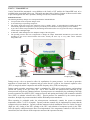
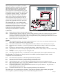
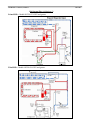
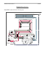
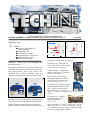
AN EXCHANGE OF TECHNICAL INFORMATION
VOLUME 19 NUMBER 1 ABOUT CARRIER TRANSICOLD CONTAINER PRODUCTS
June 2013
Inside This Issue
TechFact
NEW Look ThinLINE® and
.
PrimeLINE®units
NaturaLINE™ unit
Evaporator Motor Adapter
Unit Model Number Configuration
ERR1 Reminder (software)
Software Release Update
(See Refrigerant Flow, addendum number 1)
Following is a listing of the key changes:
TechFact – NEW Look to the ThinLINE® and
PrimeLINE® units.
PrimeLINE models 561-2xx and greater along with
ThinLINE models 541-5xx and greater have a new
look (shown below), which is the result of our
continuous drive to improve efficiency while also
reducing overall weight and improving serviceability.
Condenser Coil – Changed from
a flat, 7 mm coil to a C shaped 7mm
2 row coil (coil p/n 81-04203-20).
Condenser Motor – Changed from
single to three phase (p/n 54-00655-20,
fan blade p/n 38-00620-01).
Receiver Tank and Filter Drier –
Moved from under the condenser
coil to next to the condenser coil
(PL p/n 79-04049-00, TL p/n - 01).
Control Box Door – The unit display
and the keypad are installed on the
door. Door now opens outward
from the unit. Door, less keypad and
display, is part number 79-04018-00 w/Philips screws, -01 w/
Latches).
With this new look the refrigeration cycle remains the
same as the previous PrimeLINE and ThinLINE units.
Updates primarily consist in either the relocation of
hardware and/or the standardization of hardware used.
Evaporator Coil – Changed
from inward sloped to an
outward sloped coil.
(p/n 81-04186-20).
More information on each of these units can be
obtained from the Carrier Transicold website,
www.container.carrier.com and by downloading the
Service Operations and Parts Manuals.
TechFact – NaturaLINE unit
Carrier Transicold has announced a new addition to the family of NT models, the NaturaLINE unit, to be
available in the second half of this year. This article previews some of the key features of this new unit in order
to provide insight into the unit’s operation, utilizing CO2 (R744), a natural refrigerant.
Structural Overview
The following machinery changes were incorporated into the NaturaLINE unit:
• Two-speed fans for the evaporator and gas cooler.
• A new multi-stage reciprocating compressor.
• The electric motor that powers the compressor runs at variable speeds. A custom-designed variable-speed drive
electronically adjusts the compressor’s speed, to provide the precise amount of cooling capacity to meet demand.
• A gas cooler coil that wraps around the fan, maximizing heat-transfer surface area for greater efficiency in a design that
is both compact and lightweight.
• A flash tank, which manages the flow and phase change of the refrigerant.
• The operating software has been reengineered to manage the unique NaturaLINE mechanical system while still
providing an easy–to-use control interface that works virtually the same way as every other Carrier container
refrigeration unit.
Gas Cooler
Advanced Controller
Flash Tank
Multi-stage Compressor
Variable
Frequency Drive
During start up, valves are opened to allow for equalization of system pressures. As the start up procedure
transitions to control mode, the evaporator and gas cooler fans are cycled on, the electronic expansion valve
(EEV) is energized, and the compressor and variable frequency drive (VFD) are ramped up.
During normal operation, temperature control is maintained by VFD speed, system pressures and superheat
control and cycling of the gas cooler fan. All of these variables are monitored and controlled by the
microprocessor using the new enhanced software. System pressures are controlled by the positioning of the high
pressure expansion valve (HPXV), EEV, compressor speed, and opening and closing of the economizer solenoid
valve (ESV) or unloader solenoid valve (USV). System pressures are monitored by the suction pressure
transducer, the high side pressure transducer and the flash tank pressure transducer.
When operating in perishable mode, the microprocessor continuously controls the system to maintain
temperature within +/−0.25°C of setpoint. Capacity reduction controls may be implemented to ensure that the
compressor does not shutdown. Capacity reduction measures include modulation of the Gas Cooler Fan speed
(high, low, off), closing of the ESV, opening of the USV, and reduction of compressor speed via the VFD.
After all capacity reduction measures have been implemented, if the temperature continues to fall below the
control limit, the unit will turn off the compressor and run with evaporator fans only.
When operating in Frozen Mode or pull down,
additional controls are applied to the evaporator
fans and compressor speed. If temperature is
above the setpoint plus the control band, the
VFD will operate at maximum allowable speed.
Depending on operating conditions, the ESV may
be opened to increase capacity. As the control
temperature approaches setpoint, compressor
speed will be reduced to maintain temperature.
If the temperature should continue to fall, the
system will turn off the refrigeration circuit and
operate with evaporator fans at low speed only.
Code Select:
Cd01
Cd03
Cd13
EVAPORATOR
GAS COOLER
INTER COOLER
GAS COOLER / INTER COOLER
HPXV ESV FPT
HPRV
The NaturaLINE unit is very similar to other
Transicold NT models; however, with the added
components and features, there are also some
added function codes and alarms. To assist
technicians in troubleshooting the unit the
following codes and alarms are explained:
EEV
V
a
p
o
r
Filter
Dryer
DPT
HPS
FTPRV
SPT
CPDS
Compressor
(Multi- Stage)
Low Side
Service
Connection
Flash
Tank
ETS
GCTS
High Side Service
Connection
USV
Liquid
Line
Suction Port
Liquid
(See Refrigerant Flow, addendum number 2)
Displays the percentage of operating compressor speed.
The default display shows the compressor current. Pressing the enter key will access a down select menu. Using the
arrow key you can scroll to the current in amps “CUr”, followed by “POW” for power in watts and “PEr” for
percentage of compressor speed, same as Cd01. Pressing the enter key at any point during the down select will result
in that display being the new default Cd03 value.
Displays the pressure within the flash tank.
Alarms:
AL13
AL25
AL68
AL92
AL93
AL94
AL95
VFD Communication Failure – the alarm is generated when there is a loss of two-way communication between the
Micro-Link® 3 controller and the variable frequency drive.
Gas Cooler Fan Motor Safety – this is a display alarm that indicates that the motor’s internal protector is open.
Flash Tank Pressure Transducer – the alarm is generated when the transducer reading is outside of the acceptable
range.
Internal Fault - indicates that there is an internal fault within the variable frequency drive (VFD).
VFD Fan Fault- the alarm is caused by a high temperature condition in the VFD, usually as a result of a VFD cooling
fan failure.
VFD Trip – caused by a high current draw through the VFD.
Gas Cooler Temperature Sensor – is triggered by the sensor reading outside of the acceptable temperature range.
New Pre-trips: The following new Pre-trip tests have been added to perform diagnostic checks on main
components of the NaturaLINE unit.
P2-0
P2-1
P6-5
P6-6
P6-7
P6-8
P6-9
Gas Cooler Fan Low Speed test: checks the operation of the low speed fan.
Gas Cooler Fan High Speed test: checks the operation of the high speed fan.
Unloader Valve test – checks the opening and closing of the unloader valve.
Variable Frequency Drive – increases compressor speed and checks for an increase in discharge pressure.
High Pressure Expansion Valve - slowly closes the HPXV and checks for a pressure increase. Test passes after an
increase in discharge pressure has been detected.
Evaporator Expansion Valve - slowly opens the EEV and checks for a pressure difference. Test passes after a
pressure difference has been detected.
Economizer Solenoid Valve Test - checks the opening and closing of the solenoid valve.
This article gives you a general review of the unit. If you have any questions, please contact your regional
service engineer, or plan on attending a Carrier Transicold training school in 2013.
Mark Rogers
TechFact – Evaporator Motor Adapter
With the release of the 54-00585-20 evaporator motor
in 2002 (refer to bulletin CTR-SER02-10), an adapter
was included with the motor for use with units that
originally were equipped with motor p/n 54-00548-00.
This adaptor is no longer included with the motor and
can be purchased separately (p/n 54-00585-21).
In the case of an emergency and the adapter is not
available, the following instructions outline the steps
necessary to use a 54-00585 motor as a replacement
for a unit OEM equipped with a 54-00548 motor.
CAUTION –. ALWAYS FOLLLOW LOCK OUT / TAG OUT
PROCEDURES PRIOT TO WORKING ON THE UNIT.
1. Remove evaporator access panel for the appropriate
motor that will be replaced.
2. Disconnect motor receptacle and unit wire harness plug
and remove motor from unit.
3. Cut off the Deutsch connector, leaving approximately 1
to 2 inches of wire coming out of the motor body from the
54-00548 motor just removed from unit.
4. Take the replacement motor, 54-00585, and cut off the
Amp connector from its motor harness. Cut the wires off as
close to the connector as possible to ensure ample wire
length from motor body to replacement connector.
5. Connect the Deutsch connector assembly, from step
three above, to the 54-00585 motor making sure to match
the appropriate wire designations. (e.g.: T1 to T1, T2 to T2,
etc., refer to the units wiring diagram and schematic for
reference). It is recommended to stagger wire lengths 1 –
1.5 inches (25 – 38 mm) when making connections. The
T11 wire from the unit is not used with the 54-00585
motor. Heat shrink over the unused end of the T11 wire and
fold it back into the unit’s wiring harness and secure in
place. This wire is hot and must be secured and insulated.
6. Install replacement motor, connect to unit harness, and
Mark Donahoe
reinstall access panel.
TechFact – Unit Model Number Configuration
To successfully install software versions 5x55 and
higher, menu0115 must be used. Using an older menu
version will result in a “bAd cArd”/rEAd FAIL”
message.
The menu file image needs to be copied to the card as
normally done using the PCM Card Manager. Once
the menu0115.m2x.2048 or 4096 image is written to
the card, the card will contain menu0115 for both
ML2i and ML3 controllers.
Upon completion of loading the menu file, the latest
operational software and configuration files can be
copied to the card. For ML3 operational software
version 5x54 and earlier, the configuration file would
be the latest cfxxxxxx.ml3 (year/month/day) file. For
ML3 versions 5x55 and later the configuration file is
the latest cfxxxxxx.cf3 file. It is also still necessary to
have the cfxxxxxx.m2x configuration file on the card
when configuring ML2i controllers.
When moving a controller from one platform
(ThinLINE / EliteLINE™ / PrimeLINE) to another
you should always load the appropriate (recip/scroll)
operation software followed by model configuration.
With an ML3 controller installed with 5x55
operational software and higher, the unit configuration
information is also stored in the controller and is
updated with the .cf3 configuration file. Failure to
configure the correct model type will result in a
message “nEEd_COnFG” on the next power cycle if
the model number does not match the software type
(i.e. scroll operation software for a recip model
number).
Also, if the model configuration information in the
controller is newer than the .cf3 file on the
programming card you will receive a message “OLd
CArd”/“USE nEW”. Selecting “enter” will use the
newer model configuration information in the
controller. Pressing the down arrow will allow you to
load the older configuration information from the
card. With this, it is recommended that you select
“enter” to use the newer configuration information in
the controller and then go to the software web site and
update the .cf3 file on the card accordingly.
Tech Fact – ERR1 Reminder
In June 2011, Carrier Transicold released software
version 5352 to address aging of the flash memory on
older Micro-Link® 3 controllers (3+ years). With
this, we also posted on the website software that can
be used to reset a controller with an active ERR1.
From time to time, we continue to receive controllers
at our remanufacturing locations with an ERR1,
meaning a higher cost part was mistakenly replaced
when it could have been reset in the field. As we
work with service centers that are returning the
mistakenly diagnosed controllers, we suggest all
technicians keep this in mind when troubleshooting a
controller for an ERR1 occurrence.
TechFact – Software Release Update
Listed below are the software release versions for operating and
working with Carrier Transicold units. Prior to upgrading units
you should seek agreement from the equipment owners.
Recip (ML2i/ML3, 5156) / Scroll (ML2i/ML3, 5356)
Reciprocating Unit (ML2) – 1207
Controlled Atmosphere – 3115
DataLINE – 2.2 / DataBANK – 0513
Menu - 0115
After completing a software upgrade, it is important for the
user to check the user selectable controller selections. (i.e.
defrost setting, set point, etc.).
TechLINE is a publication of Carrier Transicold
Editor / Contributor: Perry Hoover
Contributors: Mark Donahoe, Mark Rogers,
Jack Kurz
Thanks to all who supported this release.
TECHLINE: Volume 19, Number 1
June 2013
Refrigerant Flow (Addendum 1)
PrimeLINE®: Model 69NT40-551-2XX and greater
ThinLINE®: Model 69NT40-541-5XX and greater
TECHLINE: Volume 19, Number 1
June 2013
Refrigerant Flow (Addendum 2)
NaturaLINE™: Model 69NT40-601-XXX and greater
EEV
EVAPORATOR
GAS COOLER
INTER COOLER
GAS COOLER / INTER COOLER
HPXV ESV FPT
HPRV
V
a
p
o
r
Filter
Dryer
DPT
HPS
FTPRV
Compressor
(Multi- Stage)
Low Side
Service
Connection
USV
Flash
Tank
ETS
GCTS
High Side Service
Connection
SPT
CPDS
Liquid
Line
Liquid
Suction Port