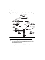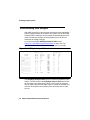
1
Avaya Communication
Manager Basic Administration
Quick Reference
03-300363
Issue 3
February 2007
Release 4.0
© 2007 Avaya Inc.
All Rights Reserved.
Notice
While reasonable efforts were made to ensure
that the information in this document was
complete and accurate at the time of printing,
Avaya Inc. can assume no liability for any errors.
Changes and corrections to the information in this
document may be incorporated in future releases.
For full legal page information, please see the
complete document, Avaya Legal Page for
Software Documentation, Document number
03-600758.
To locate this document on the website, simply go
to http://www.avaya.com/support and search for
the document number in the search box.
Documentation disclaimer
Avaya Inc. is not responsible for any
modifications, additions, or deletions to the
original published version of this documentation
unless such modifications, additions, or deletions
were performed by Avaya. Customer and/or End
User agree to indemnify and hold harmless
Avaya, Avaya's agents, servants and employees
against all claims, lawsuits, demands and
judgments arising out of, or in connection with,
subsequent modifications, additions or deletions
to this documentation to the extent made by the
Customer or End User.
Link disclaimer
Avaya Inc. is not responsible for the contents or
reliability of any linked Web sites referenced
elsewhere within this documentation, and Avaya
does not necessarily endorse the products,
services, or information described or offered
within them. We cannot guarantee that these links
will work all of the time and we have no control
over the availability of the linked pages.
Warranty
Avaya Inc. provides a limited warranty on this
product. Refer to your sales agreement to
establish the terms of the limited warranty. In
addition, Avaya’s standard warranty language, as
well as information regarding support for this
product, while under warranty, is available through
the following Web site:
http://www.avaya.com/support
Copyright
Except where expressly stated otherwise, the
Product is protected by copyright and other laws
respecting proprietary rights. Unauthorized
reproduction, transfer, and or use can be a
criminal, as well as a civil, offense under the
applicable law.
Avaya support
Avaya provides a telephone number for you to use
to report problems or to ask questions about your
product. The support telephone number
is 1-800-242-2121 in the United States. For
additional support telephone numbers, see the
Avaya Web site: http://www.avaya.com/support
Contents
1: Getting started . . . . . . . . . . . . . . . . . . .
7
Overview of Avaya Communication Manager . . . . . . .
System running Avaya Communication Manager . . .
Telephone types . . . . . . . . . . . . . . . . . . . . .
7
8
9
Accessing your system . . . . . . . .
Logging into the system . . . . .
Setting the system time and date.
Saving changes . . . . . . . . . .
Temporary save . . . . . . . .
Permanent backup . . . . . .
Saving announcements . . . .
Logging off the system . . . . . .
.
.
.
.
.
.
.
.
.
.
.
.
.
.
.
.
.
.
.
.
.
.
.
.
.
.
.
.
.
.
.
.
.
.
.
.
.
.
.
.
.
.
.
.
.
.
.
.
.
.
.
.
.
.
.
.
.
.
.
.
.
.
.
.
.
.
.
.
.
.
.
.
10
10
11
12
12
12
14
14
2: Planning the system . . . . . . . . . . . . . . . .
17
Understanding the dial plan . . . . . . . . . . . . . . . .
17
Dial plans with Avaya Communication Manager .
Displaying your dial plan . . . . . . . . . . . .
Punctuation . . . . . . . . . . . . . . . . .
Modifying your dial plan . . . . . . . . . . . .
Adding extension ranges to your dial plan . .
Adding feature access codes to your dial plan
Multi-location dial plans . . . . . . . . . . . .
Prerequisites . . . . . . . . . . . . . . . . .
.
.
.
.
.
.
.
.
18
18
22
23
24
24
25
26
Changing feature access codes . . . . . . . . . . . . . .
26
3: Managing telephones . . . . . . . . . . . . . . .
29
Adding new telephones . . . . . . . . . . . . . . . . . .
Gathering necessary information. . . . . . . . . . . .
Physically connecting the telephone . . . . . . . . .
29
30
32
.
.
.
.
.
.
.
.
.
.
.
.
.
.
.
.
.
.
.
.
.
.
.
.
.
.
.
.
.
.
.
.
.
.
.
.
.
.
.
.
Issue 3 February 2007
3
Contents
Completing the Station screens . . . . . .
Using station templates to add telephones
Using an alias . . . . . . . . . . . . . . . .
Adding or changing feature buttons . . . .
.
.
.
.
33
34
36
38
Customizing your telephone . . . . . . . . . . . . . . . .
40
Upgrading telephones . . . . . . . . . . . . . . . . . . .
41
Swapping telephones . . . . . . . . . . . . . . . . . . . .
Swapping non-IP telephones . . . . . . . . . . . . . .
Swapping IP telephones . . . . . . . . . . . . . . . .
41
42
42
Removing telephones
. . . . . . . . . . . . . . . . . . .
43
4: Managing features . . . . . . . . . . . . . . . . .
47
Changing feature parameters . . . . . . . . . . . . . . .
47
Setting up Abbreviated Dialing
. . . . . . . . . . . . . .
49
Creating pickup groups . . . . . . . . . . . . . . . . . . .
52
Setting up call forwarding . . . . . . . . . . . . . . . . .
54
Creating coverage paths . . . . . . . . . . . . . . . . . .
Defining time-of-day coverage . . . . . . . . . . . . .
Creating coverage answer groups . . . . . . . . . . .
55
58
59
Setting up advanced call coverage . . . . . . . . .
Covering calls redirected to an off-site location
Before you start . . . . . . . . . . . . . . . .
Defining coverage for calls redirected to
external numbers . . . . . . . . . . . . . . . . .
Defining telecommuting coverage . . . . . . . .
. . .
. . .
. . .
60
61
61
. . .
. . .
62
66
Setting up bridged call appearances . . . . . . . . . . .
67
E911 ELIN for IP wired extensions . . . . . . . . . . . . .
71
4 Basic Administration Quick Reference
.
.
.
.
.
.
.
.
.
.
.
.
.
.
.
.
.
.
.
.
Contents
5: Routing outgoing calls . . . . . . . . . . . . . .
World class routing . . . . . . . . . . . .
Understanding ARS analysis . . . . .
Managing calling privileges . . . . . .
Displaying ARS analysis information
.
.
.
.
73
74
75
76
Modifying call routing . . . . . . . . . . . . . . . . . . . .
Adding a new area code or prefix . . . . . . . . . . .
Using ARS to restrict outgoing calls . . . . . . . . . .
76
77
79
Overriding call restrictions . . . . . . . . . . . . . . . . .
81
ARS Partitioning . . . . . . . . . . . . . . . . . . . . . .
Setting up a partition group. . . . . . . . . . . . . . .
Assigning a telephone to a partition group . . . . . .
82
83
85
6: Enhancing system security . . . . . . . . . . . .
89
Preventing toll fraud . . . . . . . . . . . . . . . . . . . .
Top 15 tips to help prevent toll fraud . . . . . . . .
90
90
Using reports to detect problems . . . . . . . . . . . . .
Call Detail Recording . . . . . . . . . . . . . . . . . .
Security Violations Notification . . . . . . . . . . . .
93
93
95
7: Keeping records . . . . . . . . . . . . . . . . . .
97
Paper records . . . . . . . . . . . . .
System information . . . . . .
Specific extension information
Other information . . . . . . .
.
.
.
.
.
.
.
.
.
.
.
.
.
.
.
.
.
.
.
.
.
.
.
.
.
.
.
.
.
.
.
.
.
.
.
.
.
.
.
.
.
.
.
.
.
.
.
.
.
.
.
.
.
.
.
.
.
.
.
.
.
.
.
.
.
.
.
.
73
.
.
.
.
.
.
.
.
97
98
99
100
Preparing to contact Avaya . . . . . . . . . . . . . . . . .
Notes . . . . . . . . . . . . . . . . . . . . . . . . .
101
102
Index . . . . . . . . . . . . . . . . . . . . . . . . . . 103
Issue 3 February 2007
5
Contents
6 Basic Administration Quick Reference
Overview of Avaya Communication Manager
starting
1: Getting started
This section contains a brief overview of a system running Avaya
Communication Manager. It also explains how to log in to your
communication system, change the date and time, save changes to
the system, and log off.
Overview of Avaya Communication Manager
Avaya Communication Manager organizes and routes voice, data,
image, and video transmissions. Your system can be connected to
communications paths that transmit voice and data signals between
the telephone system and a central office, and to other public and
private networks. Figure 1: Sample system running Avaya
Communication Manager on page 8 shows typical system
connections, software packages, and additional hardware.
To find more detailed information and a comprehensive overview of
Communication Manager, see the Overview for Avaya
Communication Manager.
Note:
Note:
Your equipment may be different from the equipment shown
in the figure.
Issue 3 February 2007
7
Getting started
Figure 1: Sample system running Avaya Communication Manager
System
Access
Terminal
SAT
Avaya Media
Server
SO
ALM
TST
ACT
SIG
EI
SM
EM
SI
EO
E1/T1
ALM
TST
ACT
OK TO
REMOVE
EIA 530A DCE
ALM
TST
ACT
SHUT DOWN
SERVICES
USB 1
USB 2
1
2
3
4
5
6
7
8
1
2
3
4
5
6
7
8
ALM
TST
ACT
Avaya Interactive
Response (IR)
Avaya
Media
Gateway
IP Telephone
Printer
Server
LAN
Gateway
Printer
Basic Call
Management BCMS
System
Printer
Workstation
AUDIX
LAN
Workstation
CMS
Printer
Call
Management
System
Computer
CAS
ASAI
screen
pops
Link to
ASAI
Server
Printer
Call
Accounting
System
Call Detail
CDR Recorder
Printer
Computer
cydfg4r2 LAO 070803
Computer
Computer
System running Avaya Communication Manager
Your system running Communication Manager may include some or
all of the following components:
●
Avaya Interactive Response (IR)— provides response to
spoken information
8 Basic Administration Quick Reference
●
System Access Terminal (SAT) — allows remote connection for
administration and reports
●
Basic Call Management System (BCMS) — collects information
and prints reports on call-center performance
●
ASAI — allows integration between adjunct computers and
systems running Communication Manager
●
Call Detail Recording (CDR) — collects, stores, filters, and
prints records on calls handled by your system
●
Message Manager — access to AUDIX voice processing on a
personal computer
●
PC with terminal emulation software — allows remote system
administration from a personal computer
●
Call Accounting System (CAS) — uses call records to create
billing reports for the hospitality industry
●
Call Management System (CMS) — collects information and
generates reports on telemarketing centers
●
AUDIX workstation — allows you to administer voice mail
●
System printer/LAN gateway — connects to the system printer
and local area network server
starting
Overview of Avaya Communication Manager
Telephone types
Your system may have a combination of telephone types
administered as user telephones. As you make changes to your
system, you’ll need to know whether each telephone is an analog,
digital, hybrid, ISDN, IP, or SIP telephone.
For a list of telephone types and how they should be administered,
see the “Station” section in the Administrator Guide for Avaya
Communication Manager.
Note:
Note:
Avaya no longer supports some older telephone models.
Issue 3 February 2007
9
Getting started
Accessing your system
You need to log in before you can administer your communication
system. To log in, you need to know:
●
your login and password
●
the type of terminal or terminal emulation program that you are
using
Logging into the system
Note:
Note:
If your system requires Access Security Gateway
procedures, see the Administrator Guide for Avaya
Communication Manager, for more information.
To log in:
1. At the prompt (Figure 2: Terminal screen for login on page 10),
type your login ID. Press Enter.
The system prompts you for your password.
2. Type your password. Press Enter.
Your password does not display on the screen. Be sure to keep
your password private.
The system prompts you for your terminal type. (The terminal
type enclosed in square brackets is the default.)
Figure 2: Terminal screen for login
Login:
Password:
System: XXXXXX
Software Version: xxxxxxxxxxxx
Terminal Type: (513, 715, 4410, 4425, VT220): [513]
10 Basic Administration Quick Reference
Accessing your system
3. Press Enter if you are using the default terminal. Otherwise,
enter the terminal type. Press Enter.
starting
Once you log in, the system displays the word Command. The
system is now ready to accept a new command.
Setting the system time and date
Update the system time and date for events such as leap year or
daylight savings time. The correct time and date ensure that records
are correct.
Note:
Note:
Changing the date and time may modify Call Detail
Recording (CDR) data by 9 hours and 59 minutes.
Therefore, you should change the date and time after
normal business hours.
To set the system time and date:
1. Type set time. Press Enter.
The system displays the Date and Time screen (Figure 3: Date
and Time screen on page 11).
Figure 3: Date and Time screen
DATE AND TIME
DATE
Day of the Week: __________
Day of the Month: __
Month: _________
Year: ____
TIME
Hour:__
Minute:__
Second: XX
Type:________
Daylight Savings Rule: ___
2. Complete the appropriate fields.
Use a 24-hour clock to set the hour. For example, for 2:00 p.m.
(14:00) type 14. Do not try to update the Second field because it
automatically resets to 0 when you press Enter.
Issue 3 February 2007
11
Getting started
3. Press Enter to save your changes.
4. Type display time. Press Enter to double check the new date
and time.
Note:
Note:
When you change the date or time, some display telephones
may not automatically refresh the display. If this happens,
have each user press the date/time button on their
telephone and the display should update.
For more information about setting the date and time on your system,
see the Administrator Guide for Avaya Communication Manager.
Saving changes
There are two methods for saving changes to your system: temporary
saves and permanent backups.
Temporary save
As you are working with the system, your changes to the system
memory are considered temporary. These changes are lost if your
system loses power before the next permanent save (or backup).
1. Press Enter to save any changes you make on a screen.
When you press Enter, the words “command successfully
completed” appear, and the cursor returns to the command
prompt.
Permanent backup
A permanent backup copies your changes from the system memory
to a card (also called a flash ROM), disk, or tape. You can perform
manual backups or your system may be administered to
automatically backup every 24 hours.
12 Basic Administration Quick Reference
Accessing your system
Note:
To determine if your system backs up automatically, type
display system-parameters maintenance and see
if you have scheduled maintenance.
starting
Note:
When you make large changes, perform a manual backup in case
your system loses power before the next backup.
To create a backup:
1. Be sure that the backup card or tape is in place.
2. Check the alarms panel and clear any active alarms.
3. Type save translation. Press Enter.
The system displays the Save Translation screen
(Figure 4: Save Translation screen on page 13).
The save process may take up to 10 minutes. You cannot
administer your system while the save process takes place.
If an error message appears in the Command Completion
Status field, clear the error and repeat the save process.
Figure 4: Save Translation screen
SAVE TRANSLATION
Processor
SPE_A
Command Completion Status
Success
Error Code
0
It is a good idea to have at least two backups. You can run the backup
again to a second card, or you can copy an automatic backup with
the backup command (if your system allows). You may want to keep
this second (or a third) backup off premises to ensure you could
recover from a disaster or system failure.
For more information about performing backups of your system, see
the Administrator Guide for Avaya Communication Manager.
Issue 3 February 2007
13
Getting started
Saving announcements
You can save announcements only if your system has an integrated
announcement board and you have administered announcements.
For information about Voice Announcements over LAN (VAL) and
VAL Manager, see the Avaya Communication Manager Advanced
Administration Quick Reference.
If you change your recorded announcements and you have a
TN750C board, the system automatically saves your changes to the
on-board FLASH memory.
If you have a TN750 or TN750B board, you need to manually save
the recorded announcements on your system.
1. Type save announcements. Press Enter to save the changes.
This process can take up to 40 minutes. You cannot administer
your system while the system is saving announcements.
Note:
Note:
If you have both TN750B and TN750C boards, save
announcements to the TN750B slot.
For more information about saving announcements, see the
Administrator Guide for Avaya Communication Manager.
Logging off the system
For security reasons, log off every time you leave your terminal.
1. To log off the system, type logoff. Press Enter.
You may see a security screen that indicates that you have
Remote Access, Facility Test, or Busied Out administered. You
may want to disable these features before you log off. For more
information about these features, see the Avaya Communication
Manager Basic Diagnostics Quick Reference.
14 Basic Administration Quick Reference
Accessing your system
2. Type y. Press Enter to proceed with log off.
If you use terminal emulation software to administer the system, you
should log off the system and exit the emulation application before
alternating or changing to another software package.
Issue 3 February 2007
15
starting
This screen also indicates whether or not you have any active
minor or major alarms that you should address before you end
your session.
Getting started
16 Basic Administration Quick Reference
Understanding the dial plan
planning
2: Planning the
system
This section provides you with background on system-wide functions.
It explains how to read and use your dial plan, and shows you how to
make simple changes such as adding extension ranges. This section
also explains how to assign feature access codes.
Understanding the dial plan
Your dial plan tells your system how to interpret dialed digits. For
example, if you dial 9 on your system to access an outside line, it is
actually the dial plan that tells the system to find an external trunk
when a dialed string begins with a 9.
The dial plan also tells the system how many digits to expect for
certain calls. For example, the dial plan may indicate that all internal
extensions are 4-digit numbers that start with 1 or 2.
Note:
Note:
The dial plan serves as the basis for almost everything in the
system, so we wanted to be sure you have a clear
understanding of how to read and update your dial plan. The
screens shown here may not exactly match your system.
For a complete discussion of the dial plan, see the “Dial Plan” and
“Uniform Dial Plan” feature descriptions in the Feature Description
and Implementation for Avaya Communication Manager.
Issue 3 February 2007
17
Planning the system
Dial plans with Avaya Communication
Manager
Communication Manager allows you to create your dial plan using up
to thirteen digits.
Let us take a look at an example dial plan so you’ll know how to read
your system’s dial plan. The following figure shows an example of a
simple dial plan.
Displaying your dial plan
You might want to take this opportunity to look at and interpret your
own dial plan. To display your system’s dial plan:
1. Type display dialplan analysis. Press Enter.
The system displays the Dial Plan Analysis Table screen
(Figure 5: Dial Plan Analysis Table screen on page 18).
Figure 5: Dial Plan Analysis Table screen
display dialplan analysis
DIAL PLAN ANALYSIS TABLE
Page 1 of x
Percent Full:
Dialed
String
303538
23
Total
Length
7
7
Call
Type
ext
ext
Dialed
String
908
Total
Length
5
4
Call
Type
ext
A set of three columns indicate how long the dialed string is for each
type of call. For example, this dial plan shows that when users dial a
7-digit number that starts with 303538, they are dialing an extension.
18 Basic Administration Quick Reference
Dial plans with Avaya Communication Manager
The third Call Type column may have any of the following call types:
Attendant (attd) — Defines how users call an attendant. Attd
access numbers can be any number from 0 to 9 and only
contain one or two digits. In our example figure, the system
calls an attendant when users dial 0.
If you use the Attendant Access Code field on the Feature
Access Code (FAC) screen, you cannot make an “attd” entry
here. For more information, see Multi-location dial plans on
page 25, and the Administrator Guide for Avaya Communication
Manager.
●
Automatic Alternate Routing (aar) — Used to route calls within
your company over your own private network.
Note:
Before you can use this call type in your dial plan, the ARS/
AAR Dialing without FAC feature must be enabled. To
check if this is enabled, use the display
system-parameters customer-options command.
Note:
When dialing digits of Call Type aar, as soon as the dialed digits
have reached the administered length, the digits are treated as if
an AAR feature access code (FAC) was dialed. Control is
transferred and the digits are routed according to the AAR
Analysis and Digit Conversion screens.
In our example, extensions of 3xxx cannot be dialed directly.
Whenever a user dials the first digit of 3, the system immediately
interprets the dialed string as an AAR string and transfers control
to AAR.
Extensions of 3xxx can only be accessed using AAR Digit
Conversion. That is, you must dial a longer AAR number from
which AAR Digit Conversion deletes leading digits to screen a
number of the screen 3xxx.
●
Automatic Route Selection (ars) — Used to route calls that go
outside your company over public networks. ARS is also used
to route calls to remote company locations if you do not have a
private network.
Issue 3 February 2007
19
planning
●
Planning the system
Note:
Before you can use this call type in your dial plan, the ARS/
AAR Dialing Without FAC feature must be enabled. To
check if this is enabled, use the display
system-parameters customer-options command.
Note:
When dialing digits of Call Type ars, as soon as the dialed digits
have reached the administered length, the digits are treated as if
an ARS feature access code (FAC) was dialed. Control is
transferred and the digits are routed according to the ARS
Analysis and Digit Conversion screens.
In our example, extensions of 4xxxx cannot be dialed directly.
Whenever a user dials the first digit of 4, the system immediately
interprets the dialed string as an ARS string and transfers control
to ARS.
Extensions of 4xxxx can only be accessed using ARS Digit
Conversion. That is, you must dial a longer ARS number from
which ARS Digit Conversion deletes leading digits to screen a
number of the screen 4xxxx.
For more information, see Understanding ARS analysis on
page 74.
●
Dial Access Codes (dac) — Allows you to use trunk access
codes (tac) and feature access codes (fac) in the same range.
For example, you could define the group 100–199 for dacs,
which would allow both facs and tacs in that range. Dial access
codes can start with any number from 1 to 9 and contain up to
4 digits. The first digit can also be * and #. In our example
figure, dial access codes begin with 1 and must be 3 digits long,
so this company can have a feature access code set to 133 and
a trunk access code assigned to 134.
●
Extensions (ext) — Defines extension ranges that can be used
on your system. In our example, extensions must be in the
ranges: 3000–3999, 40000–49999, 5000000–5999999,
6000000–6999999, and 90000–99999.
20 Basic Administration Quick Reference
●
Feature Access Codes (fac) — facs can be any number from 1
to 9 and contain up to 4 digits. You can use * or #, but only as a
first digit. In our example, this company can use *31 to activate
a feature and use #31 to deactivate the same feature. Our
example also shows that one fac can be set to 8 (first digit 8,
only one digit long).
●
Uniform Dial Plan (udp) — The udp call type works identically
with the ext call type, with this exception:
- If dialed digits match the call type of udp, Communication
Manager automatically checks the UDP Table first to see if
there is a match, regardless of the value in the UDP
Extension Search Order field on the Dial Plan Parameters
screen. If there is no match, Communication Manager then
checks the local server.
- If dialed digits match the call type of ext, Communication
Manager checks the value in the UDP Extension Search
Order field on the Dial Plan Parameters screen.
●
If the value in the UDP Extension Search Order field on
the Dial Plan Parameters screen is udp-table-first,
Communication Manager checks the UDP Table first to
see if there is a match. If there is no match,
Communication Manager then checks the local server.
●
If the value in the UDP Extension Search Order field on
the Dial Plan Parameters screen is
local-extensions-first, Communication Manager checks
the local server first to see if there is a match. If there is no
match, Communication Manager then checks the UDP
Table.
The udp call type allows Communication Manager to
recognize strings of 14 to 18 digits, which are longer than the
maximum extension length of 13 digits. However, the udp call
type can be used with any length in case this provides a
useful new capability to customers.
Issue 3 February 2007
21
planning
Dial plans with Avaya Communication Manager
Planning the system
Punctuation
Communication Manager allows customers to specify punctuation
formats for 6-digit through 13-digit extensions. This table shows how
many punctuation marks are allowed for 6 to 13 digit extensions:
Note:
Note:
Punctuation is not allowed on extensions of 5 digits or less.
Extension
Length
Maximum
Punctuation
Marks
Maximum
Total
Length
6
2
8
7
1
8
8
3
11
9
3
12
10
3
13
11
2
13
12
1
13
13
0
13
The Dial Plan Parameters screen works with the Dial Plan Analysis
Table to define your system’s dial plan. The default values for 6-, 7-,
8-, 9-, 10-, 11-, 12-, and 13-digit fields are those shown in Figure 6.
Note:
Note:
The 13-digit entry in the Inter-Location/SAT column is
read-only.
22 Basic Administration Quick Reference
Dial plans with Avaya Communication Manager
Figure 6: Dial Plan Parameters
display dialplan parameters
Page 1
DIAL PLAN PARAMETERS
planning
Local Node Number: 2
ETA Node Number:
ETA Routing Pattern:
UDP Extension Search Order: local-extensions-first
EXTENSION DISPLAY FORMATS
6-Digit
7-Digit
8-Digit
9-Digit
10-Digit
11-Digit
12-Digit
13-Digit
Extension:
Extension:
Extension:
Extension:
Extension:
Extension:
Extension:
Extension:
Inter-Location/SAT
xx.xx.xx
xxx-xxxx
xx.xx.xx.xx
xxx-xxx-xxx
xxx-xxx-xxxx
xxxx-xxx-xxxx
xxxx-xxx-xxxx
xxxxxxxxxxxxx
Intra-Location
xx.xx.xx
xxx-xxxx
xx.xx.xx.xx
xxx-xxx-xxx_
xxx-xxx-xxxx_
xxxx-xxx-xxxx
xxxxxxxx-xxxx
xxxxxxxxxxxxx
Modifying your dial plan
It is easy to make changes to your dial plan. For example, let us add
a new range of dial access codes to the dial plan. We want to be able
to assign both facs and tacs in the 700–799 range.
1. Type change dialplan analysis. Press Enter.
The system displays the Dial Plan Analysis Table screen.
2. Move the cursor to the next available row.
3. Type 7 in the first column.
4. Type 3 in the second column.
5. Type dac in the third column.
6. Press Enter to save your changes.
Issue 3 February 2007
23
Planning the system
Adding extension ranges to your dial plan
You may find that as your needs grow you want a new set of
extensions. Before you can assign an extension to a telephone, the
extension must belong to a range that is defined in the dial plan. Let
us add a new set of extensions that start with 8 and are 6 digits long
(800000–899999).
To add this set of extensions to the dial plan:
1. Type change dialplan analysis. Press Enter.
The system displays the Dial Plan Analysis Table screen.
2. Move the cursor to the next available row.
3. Type 8 in the first column.
4. Type 6 in the second column.
5. Type ext in the third column.
6. Press Enter to save your changes.
Adding feature access codes to your dial plan
As your needs change, you may want to add a new set of feature
access codes for your system. Before you can assign a FAC on the
Feature Access Code (FAC) screen, the FACs must conform to your
dial plan.
In our example, if you want to assign a feature access code of 33 to
the Last Number Dialed feature, first you need to add a new FAC
range to the dial plan.
To add a FAC range from 30–39:
1. Type change dialplan analysis. Press Enter.
The system displays the Dial Plan Analysis Table screen.
2. Move the cursor to the next available row.
24 Basic Administration Quick Reference
Dial plans with Avaya Communication Manager
3. Type 3 in the first column.
4. Type 2 in the second column.
5. Type fac in the third column.
Multi-location dial plans
When a customer migrates from a multiple independent node
network to a single distributed server whose gateways are distributed
across a data network, it may initially appear as if some dial plan
functions are no longer available.
The Multi-location Dial Plan feature preserves dial plan uniqueness
for extensions and attendants that were provided in a multiple
independent node network, but appear to be unavailable when
customers migrate to a single distributed server.
For example, in a department store with many locations, each
location might have had its own system with a multiple independent
node network. The same extension could be used to represent a
unique department in all stores (extension 4567 might be the luggage
department). If the customer migrates to a single distributed server, a
user could no longer dial 4567 to get the luggage department in their
store. The user would have to dial the complete extension to connect
to the proper department.
Instead of having to dial a complete extension, the Multi-location Dial
Plan feature allows a user to dial a shorted version of the extension.
For example, a customer can continue to dial 4567 instead of having
to dial 123-4567.
Communication Manager takes the location prefix and adds those
digits to the front of the dialed number. The system then analyzes the
entire dialed string and routes the call based on the administration on
the Dial Plan Parameters screen.
Issue 3 February 2007
25
planning
6. Press Enter to save your changes.
Planning the system
Prerequisites
Before you can administer the Multi-location Dial Plan feature, the
Multiple Locations field on the Optional Features screen must be
set to y.
To check if the Multiple Locations field is set to y:
1. Type display system-parameters customer-options.
Press Enter.
The system displays the Optional Features screen.
2. Click Next until you see the Multiple Locations field.
- If the Multiple Locations field is set to y, your system is set
up for the Multi-location Dial Plan feature.
- If the Multiple Locations field is set to n, your system is not
set up for the Multi-location Dial Plan feature. Contact your
Avaya representative.
For a more detailed explanation of this feature, its function, and the
necessary screens, see the Administrator Guide for Avaya
Communication Manager.
Changing feature access codes
Feature access codes (FAC) allow users to activate and deactivate
features from their telephones. A user who knows the fac for a feature
does not need a programmed button to use the feature. For example,
if you tell your users that the FAC for the Last Number Dialed feature
is *33, then users can redial a telephone number by entering the
FAC, rather than needing a Last Number Dialed button on their
telephone.
26 Basic Administration Quick Reference
Changing feature access codes
Many features already have factory-set FACs. You can use these
default codes, or you can change them to codes that make more
sense to you. However, every FAC must conform to your dial plan
and must be unique. For more information about the dial plan, see
Understanding the dial plan on page 17.
planning
If you want to change the feature access code for the Call Park
feature to *72:
1. Type change feature-access-codes. Press Enter.
The system displays the Feature Access Code (FAC) screen
(Figure 7: Feature Access Code (FAC) screen on page 27).
Figure 7: Feature Access Code (FAC) screen
FEATURE ACCESS CODE (FAC)
Abbreviated Dialing List1 Access Code:
Abbreviated Dialing List2 Access Code:
Abbreviated Dialing List3 Access Code:
Abbreviated Dial - Prgm Group List Access Code:
Announcement Access Code:
Answer Back Access Code:
Auto Alternate Routing (AAR) Access Code:
Auto Route Selection (ARS) - Access Code 1:
Automatic Callback Activation:
Call Forwarding Activation Busy/DA: #22
All:
Call Park Access Code:
Call Pickup Access Code:
CAS Remote Hold/Answer Hold-Unhold Access Code:
CDR Account Code Access Code:
Change COR Access Code:
Change Coverage Access Code:
#01
#02
#03
#04
#05
179
8
*9 Access Code 2: *33
#55 Deactivation: *55
#44 Deactivation: *44
*72
#33
#06
#33
*01
#80
Data Origination Access Code: #09
Data Privacy Access Code: #10
Directed Call Pickup Access Code: #11
Issue 3 February 2007
27
Planning the system
2. Move the cursor to the Call Park Access Code field.
3. Type *72 in the Call Park Access Code field over the old code.
4. Press Enter to save your changes.
If you try to enter a code that is assigned to a feature, the system
warns you of the duplicate code and does not allow you to
proceed until you change one of them.
Note:
Note:
To remove any feature access code, delete the existing FAC
and leave the field blank.
28 Basic Administration Quick Reference
Adding new telephones
This section explains how to add, swap, or remove the telephones on
your system. This section also gives you tips for customizing your
own telephone so it has the feature buttons you need for many
administration and troubleshooting tasks.
Note:
This section does not tell you how to administer attendant
consoles or IP Softphones. If you need to add or modify an
attendant console or an IP Softphone, see the Administrator
Guide for Avaya Communication Manager.
Note:
Adding new telephones
When you are asked to add a new telephone to the system, what do
you do first? To connect a new telephone you need to do three things:
●
find an available port
●
wire the port to the cross-connect field or termination closet
●
tell the telephone system what you’re doing
Before you can determine which port to use for the new telephone,
you need to determine what type of telephone you are installing, what
ports are available, and where you want to install the telephone.
Issue 3 February 2007
29
telephones
3: Managing
telephones
Managing telephones
Gathering necessary information
Gather the following information:
1. Determine whether the telephone is an analog, digital, ISDN, IP,
or hybrid set.
You need this information to determine the type of port you need,
because the port type and telephone type must match. If you do
not know what type of telephone you have, see the “Station”
section in the Administrator Guide for Avaya Communication
Manager, for a list of telephone types and how they should be
administered.
Note:
Note:
Avaya no longer supports some older telephone models.
2. Record the room location, jack number, and wire number.
You may find this information on the jack where you want to
install the telephone, recorded in your system records, or from
the technician responsible for the physical installation.
3. Display the available boards (circuit packs) and ports — or media
modules and ports.
To view a list of available ports on your system, type list
configuration stations. Press Enter.
The system displays the System Configuration screen
(Figure 8: System Configuration screen on page 31).
Note:
Note:
Because information is slightly different for different system
configurations, portions of this chapter are divided into two
groups: MCC1, SCC1, CMC1, G600, or G650 Media
Gateways, and G350 or G700 Media Gateways.
30 Basic Administration Quick Reference
Adding new telephones
Figure 8: System Configuration screen
SYSTEM CONFIGURATION
Board Type
Code
Vintage
Assigned Ports
u=unassigned t=tti p=psa
01A05
01A06
01B05
DIGITAL LINE
ANALOG LINE
ANALOG LINE
TN754B
TN742
TN746B
000002
000010
000008
01C04
ANALOG LINE
TN746B
000008
01C05
DIGITAL LINE
TN2224
000004
01C06
01C09
01C10
HYBRID LINE
MET LINE
DIGITAL LINE
TN762B
TN735
TN754
000004
000005
000004
001V2
001V3
DCP MM
ANA MM
MM712AP
MM711AP
HW02 FW005
HW03 FW016
01
01
u
u
u
u
01
u
u
02
u
u
u
u
u
u
u
04
u
u
u
u
04
u
05
u
u
u
u
u
u
u
u
u
u
u
u
u
u
u
07
u
u
u
u
u
07
u
08
u
u
u
u
u
08
u
01 02 P
01 u u
u u u
P
u
u
P
u
u
P
u
u
P
u
u
P
u
u
u
u
u
u
u
u
u
u
u
u
u
u
u
u
03
03
u
u
u
u
u
u
u
u
telephones
Board
Number
The System Configuration screen shows all the boards (circuit
packs) or media modules on your system that are available for
connecting telephones. You can see the board number, board
type, and status of each board’s ports.
4. Choose an available port and record its port address.
Each port that is available or unassigned is indicated by a ‘u.’
Choose an available port from a board type that matches your
telephone type (such as a port on an analog board for an analog
telephone).
Every telephone must have a valid port assignment, also called a
port address. The combined board number and port number is
the port address.
MCC1, SCC1, CMC1, G600, or G650 Media Gateways: If you want to attach a telephone to the 3rd port on the 01C05 board,
the port address is 01C0503 (01=cabinet, C=carrier, 05=slot,
03=port).
Issue 3 February 2007
31
Managing telephones
G350 or G700 Media Gateways: If you want to attach a telephone to the 3rd port on the MM711
media module, the port address is 001V303 (001=number of the
G700 Media Gateway, V3=slot, 03=port).
Note:
Note:
If you add several telephones at one time, you may want to
print a paper copy of the System Configuration screen.
- To print the screen to a printer attached to the system
terminal, type list configuration stations print.
Press Enter.
- To print to the system printer that you use for scheduled
reports, type list configuration stations schedule
immediate. Press Enter.
5. Choose an extension number for the new telephone. Be sure to
note your port and extension selections on your system’s paper
records.
The extension you choose must not be previously assigned and
must conform to your dial plan. You should also determine
whether this user needs an extension that can be directly dialed
(DID) or reached through a central telephone number.
Physically connecting the telephone
Once you have collected all the information, you are ready to
physically wire the port to the cross-connect field.
If you have an Avaya representative or on-site technician who
completes the physical connections, you need to notify them that you
are ready to add the telephone to the system. To request that Avaya
install the new connections, call your Avaya representative to place
an order.
If you are responsible for making the connections yourself and if you
have any questions about connecting the port to the cross-connect
32 Basic Administration Quick Reference
Adding new telephones
field, see your system installation guide. Now you are ready to
configure the system so that it recognizes the new telephone.
Completing the Station screens
The information that you enter on the Station screen advises the
system that the telephone exists and indicates which features you
want to enable on the telephone.
telephones
To access the Station screen for the new telephone:
1. Type add station n, where n is the extension for the new
telephone. Press Enter.
The system displays the Station screen (Figure 9: Station
screen on page 33). The extension number and some default
field values appear on the screen. For example, the following
screen is for a new telephone at extension 2345.
Make sure the extension conforms to your dial plan. You can also
use the add station next command to add a telephone to
assign the next available extension.
Figure 9: Station screen
STATION
Extension:
Type:
Port:
Name:
2345
Lock Messages?
Security Code:
8411D
_______________
Coverage Path 1:
________________________ Coverage Path 2:
Hunt-to Station:
STATION OPTIONS
Loss Group:
Data Module?
Speakerphone:
Display Language:
___
___
2-way
english
_
BCC: ___
_________ TN: 1
____
COR: 1
____
COS: 1
____
Personalized Ringing Pattern: 1
Message Lamp Ext: 2345
Mute Button Enabled? y
Media Complex Ext: ____
IP Softphone? n
Issue 3 February 2007
33
Managing telephones
2. Type the model number of the telephone into the Type field.
For example, to install a 8411D telephone, type 8411D in the
Type field. Note that the displayed fields may change depending
on the model you add.
3. Type the port address in the Port field.
4. Type a name to associate with this telephone in the Name field.
The name you enter appears on called telephones that have
display capabilities. Also, some messaging applications
recommend that you enter the user’s name (last name first) and
their extension to identify the telephone.
5. Press Enter to save your changes.
To make changes to this new telephone, such as assigning coverage
paths or feature buttons, type change station n, where n is the
extension of the new telephone. Press Enter.
Using station templates to add telephones
A quick way to add telephones is to copy the information from an
existing telephone and modify it for each new telephone. For
example, you can configure one telephone as a template for an entire
work group. Then, you merely duplicate the template Station screen
to add all the other extensions in the group.
Note that only telephones of the same model can be duplicated. The
duplicate command copies all the feature settings from the template
telephone to the new telephones.
To duplicate an existing telephone using a template:
1. Type display station n, where n is the extension of the
Station screen that you want to duplicate to use as a template.
Press Enter. Verify that this extension is the one that you want to
duplicate.
2. Press Cancel to return to the command prompt.
34 Basic Administration Quick Reference
Adding new telephones
3. Type duplicate station n, where n is the extension that you
want to duplicate. Press Enter.
The system displays a blank duplicate Station screen
(Figure 10: Station screen (duplicate) on page 35).
Figure 10: Station screen (duplicate)
STATION
Port
_______
_______
_______
_______
_______
_______
_______
_______
_______
_______
Name
______________________
______________________
______________________
______________________
______________________
______________________
______________________
______________________
______________________
______________________
Security
Code
Room
________ ________
________ ________
________ ________
________ ________
________ ________
________ ________
________ ________
________ ________
________ ________
________ ________
Jack
_____
_____
_____
_____
_____
_____
_____
_____
_____
_____
Cable
_____
_____
_____
_____
_____
_____
_____
_____
_____
_____
telephones
Ext.
______
______
______
______
______
______
______
______
______
______
4. Type in the extension, port address, and telephone name for
each new telephone you want to add.
The rest of the fields are optional. You can complete them at any
time.
5. Press Enter to save your changes to system memory.
To make changes to these telephones, such as assigning coverage
paths or feature buttons, type change station n, where n is the
extension of the telephone that you want to modify. Press Enter.
Issue 3 February 2007
35
Managing telephones
Using an alias
Not every telephone model has a unique Station screen in the
system. You might have to use an available model number as an
“alias” for another. If you need to enter a telephone type that the
system does not recognize or support, use an alias.
For example, you may need to install a telephone model that is newer
than your system. In this case, you can use an available model type
that best matches the features of your telephone. You can see the
manual for your telephone to determine which alias to use. If your
manual does not have this information, contact the Communication
Manager helpline for an appropriate alias.
For example, we will create two aliases: one to add a new 6220
telephone, and one to add modems to our system.
1. See your new telephone’s manual to find the correct alias.
In our example, we find that the 6220 should be administered on
an older system as a 2500 telephone.
2. Type change alias station. Press Enter.
The system displays the Alias Station screen (Figure 11: Alias
Station screen on page 37).
36 Basic Administration Quick Reference
Adding new telephones
Figure 11: Alias Station screen
ALIAS STATION
Supported Set Type
2500
2500
_____
_____
_____
_____
_____
_____
_____
_____
_____
telephones
Alias Set Type
6220
modem
_____
_____
_____
_____
_____
_____
_____
_____
_____
’#’ indicates previously aliased set type is now native
3. Type 6220 in the Alias Set Type field.
This is the name or model of the unsupported telephone.
4. Type 2500 in the Supported Set Type field.
This is the name or model of the supported telephone.
5. Type modem in the second Alias Set Type field.
You can call the alias set anything you like. Once you define the
alias, you can use the alias set in the Type field on the Station
screen.
6. Type 2500 in the second Supported Set Type field.
Entering 2500 indicates to the system that these models are
basic analog devices.
7. Press Enter to save your changes.
Now you can follow the instructions for adding a new telephone (or
adding a fax or modem). Communication Manager now recognizes
the new type (6220 or modem) that you entered in the Type field.
Be sure to see the manual for your telephone for instructions on how
to set feature buttons and call appearance buttons.
Issue 3 February 2007
37
Managing telephones
Note:
Note:
If you need to use an alias for a telephone, you may not be
able to take advantage of all the features of the new
telephone.
Adding or changing feature buttons
Once you add a telephone to the system, you can use the Station
screen to change the settings for the telephone, such as adding or
changing feature button assignments. The system allows you to
assign features or functionality to each programmable button. It is up
to you to decide which features you want for each telephone and
which feature you want to assign to each button.
Note:
Note:
If you have 6400-series telephones, your users can
administer some of their own feature buttons. For more
information, see “Setting up Terminal Self Administration” in
the Administrator Guide for Avaya Communication Manager.
To assign feature buttons:
1. Type change station n, where n is the extension for the
telephone you want to modify. Press Enter.
The system displays the Station screen.
2. Click Next until you see the Feature Button Assignment fields.
Some telephones have several feature button groups. Make sure
that you are changing the correct button. If you do not know
which button on the telephone maps to which button-assignment
field, see the manual for your telephone, or see the Administrator
Guide for Avaya Communication Manager.
3. Move the cursor to the field that you want to change.
38 Basic Administration Quick Reference
Adding new telephones
4. Type the button name that corresponds to the feature that you
want to add.
To determine feature button names, press Help or see the
Administrator Guide for Avaya Communication Manager.
5. Press Enter to save your changes.
Some telephones have default assignments for buttons. For example,
the following figure shows that the 8411D includes defaults for 12
softkey buttons. It already has assignments for features like Leave
Word Calling and Call Forwarding.
telephones
Figure 12: Default softkey assignments for an 8411D telephone
STATION
SOFTKEY BUTTON ASSIGNMENTS
1:
2:
3:
4:
5:
6:
7:
8:
9:
10:
11:
12:
lwc-store
lwc-cancel
auto-cback
timer
call-fwd
call-park
date-time
priority
abr-prog
abr-spchar
abr-spchar
abr-spchar
Ext: _____
Char: ~p
Char: ~m
Char: ~w
If you do not use an alias, you can easily assign different features to
these buttons if you have different needs.
If you use an alias, you must leave the default softkey button
assignments. The system allows you to change the button
assignments on the screen, and the features work on the alias
telephone. However, the labels on the display do not change.
Issue 3 February 2007
39
Managing telephones
Customizing your telephone
This section provides recommendations for setting up or enhancing
your personal telephone. You need a telephone that is powerful
enough to allow you to use all the features you may give to other
employees. You may want to add feature buttons that allow you to
monitor or test the system, so that you can troubleshoot the system
from your telephone.
It will be much easier to monitor and test your system if you have a
telephone with:
●
a large multi-button display (such as 8434D or 8410D)
●
a class of service (cos) that has console permissions
●
the following feature buttons
-
ACA and Security Violations (assign to lamp buttons)
-
Busy verify
-
Cover message retrieval button
-
Major/minor alarm buttons
-
Trunk ID buttons
-
Verify button
Once you select a telephone, you’ll want to determine if you want to
place this telephone at your desk or in the system room. If the
telephone is in the system room (near the system administration
terminal), you can quickly add or remove feature buttons to test
features and facilities. You may decide that you want a telephone at
both your desk and in the system room — it’s up to you.
You may also find it handy to set up multiple telephones for testing
applications and features before you provide them to users. You may
want to have a telephone that mimics each type of user telephone in
your organization. For example, if you have four basic telephone
templates, one for executives, one for marketing, one for technicians,
40 Basic Administration Quick Reference
Upgrading telephones
and one for other employees, you may want to have examples of
each of these telephones so you can test new features or options.
Once you are satisfied that a change works on the test telephone,
you can make the change for all the users in that group.
Upgrading telephones
telephones
If you want to change telephone types for a user and do not need to
change locations, you can just access the Station screen for that
extension and enter the new model number.
Note:
Note:
This method can be used only if the new telephone type
matches the existing port type (such as digital telephone
with a digital port).
For example, if a user at extension 4556 currently has a 7410+
telephone and you want to replace it with a new 6408D+ telephone:
1. Type change station 4556. Press Enter.
The system displays the Station screen for extension 4556.
2. In the Type field, overwrite 7410+ with 6408D+.
3. Press Enter to save your changes.
Now you can access the functions and feature buttons that
correspond to an 6408D+ telephone.
Swapping telephones
You will often find that you need to move or swap telephones. For
example, employees moving from one office to another may want to
bring their telephones.
Issue 3 February 2007
41
Managing telephones
Swapping non-IP telephones
To swap one non-IP telephone (phone A) with another non-IP
telephone (phone B), you change telephone A’s port assignment to x,
change telephone B’s port assignment to A’s old port, and, finally,
change the x for telephone A to B’s old port.
These swapping instructions work only if the two telephones are the
same type (both digital or both analog, etc.).
Note:
Note:
You can use Terminal Translation Initialization (TTI) to
merge an x-ported extension to a valid port. You can also
use Automatic Customer Telephone Rearrangement (ACTR)
to unplug certain telephones from one location to move them
to a new location without additional system administration.
For information about TTI and ACTR, see the Administrator
Guide for Avaya Communication Manager.
Swapping IP telephones
To swap an IP telephone, simply move the telephone and update the
site data (see step #7 in the following instructions). For an IP
telephone, you should also update the emergency 911 information.
See E911 ELIN for IP wired extensions on page 71 for more
information.
For example, to swap telephones for extension 4567 (port 01C0505)
and extension 4575 (port 01C0516), complete the following steps:
1. Type change station 4567. Press Enter.
2. Record the current port address (01C0505) and type x in the
Port field.
3. Press Enter to save your changes.
4. Type change station 4575. Press Enter.
42 Basic Administration Quick Reference
Removing telephones
5. Record the current port address (01C0516).
6. Type 01C0505 in the Port field.
This is the port that used to be assigned to extension 4567.
7. Update the Room and Jack fields.
8. Press Enter to save your changes.
9. Type change station 4575 again. Press Enter.
10. Type 01C0516 in the Port field.
telephones
This is the port that used to be assigned to extension 4575.
11. Update the Room and Jack fields.
12. Press Enter to save your changes.
13. Physically unplug the telephones and move them to their new
locations.
When you swap telephones, the system keeps the old button
assignments. If you are swapping to a telephone with softkeys, the
telephone could have duplicate button assignments, because
softkeys have default assignments. You may want to check your
button assignments and modify them as necessary.
Removing telephones
Before you physically remove a telephone from your system, check
the telephone’s status, remove it from any group or usage lists, and
then delete it from the system’s memory.
For example, to remove a telephone at extension 1234:
1. Type status station 1234. Press Enter.
The system displays the General Status screen.
Issue 3 February 2007
43
Managing telephones
2. Make sure that the telephone:
●
is plugged into the jack
●
is idle (not making or receiving calls)
●
has no messages waiting (message waiting lamp)
●
has no active buttons (such as Send All Calls or Call
Forwarding)
3. Type list groups-of-extension 1234. Press Enter.
The system displays the Extension Group Membership screen.
The Extension Group Membership screen shows whether the
extension is a member of any groups on the system.
4. Press Cancel when you are finished reviewing the Extension
Group Membership screen.
5. If the extension belongs to a group, access the group screen and
delete the extension from that group.
For example, if extension 1234 belongs to pickup group 2, type
change pickup group 2 and delete the extension from the
list.
6. Type list usage extension 1234. Press Enter.
The system displays the Usage screen. The Usage screen
shows whether the extension is used in any vectors, has any
bridged appearances, or used as a controller.
7. Press Cancel when you are finished reviewing the Usage
screen.
8. If the extension appears on the Usage screen, access the
appropriate feature screen and delete the extension.
For example, if extension 1234 belongs to hunt group 2, type
change hunt group 2 and delete the extension from the list.
9. Type change station 1234. Press Enter.
10. Delete any bridged appearances or personal abbreviated dialing
entries. Press Enter.
44 Basic Administration Quick Reference
Removing telephones
11. Type remove station 1234. Press Enter.
The system displays the Station screen for this telephone so you
can verify that you are removing the correct telephone.
Note:
Note:
Be sure to record the port assignment for this jack in case
you want to use it again later.
12. If this is the correct telephone, press Enter.
If the system responds with an error message, the telephone is
busy or still belongs to a group. Press Cancel to stop the
request, correct the problem, and enter remove station
1234 again.
13. Remove the extension from voice mail service if the extension
has a voice mailbox.
14. Type save translation. Press Enter to save your changes.
Note:
Note:
You do not need to delete the extension from coverage
paths. The system automatically adjusts coverage paths to
eliminate the extension.
Now you can unplug the telephone from the jack and store it for future
use. You do not need to disconnect the wiring at the cross-connect
field. The extension and port address remain available for
assignment at a later date.
Once you successfully remove a telephone, that telephone is
permanently erased from system memory. If you want to reactivate
the telephone, you have to add it again as though it were a new
telephone.
Issue 3 February 2007
45
telephones
The system responds with the message: command
successfully completed.
Managing telephones
46 Basic Administration Quick Reference
Changing feature parameters
4: Managing features
Changing feature parameters
You can modify the system parameters that are associated with some
of the system features. For example, you can use the system
parameters to allow music to play if callers are on hold or to allow
trunk-to-trunk transfers on the system.
Note:
Note:
You can find most of the system-wide parameters on the
Feature-Related System Parameters screen. However, if
you have DEFINITY ECS R6.3.1 or later, some parameters
have moved to new screens, such as the System
Parameters Call Coverage/Call Forwarding screen. See
the manual that corresponds to your software.
Generally, Avaya sets your system parameters when your system is
installed. However, you can change these parameters as your
organization’s needs change.
As an example, say that your company uses the Call Park feature,
where a call can be put on hold and picked up from any other
telephone within the system. You need to change the time limit for
parked calls from 10 to 5 minutes.
Issue 3 February 2007
47
features
This section explains how to administer some of the major
Communication Manager features. It provides instructions for
changing feature parameters, using abbreviated dialing, creating
pickup groups, setting up call forwarding, defining coverage paths,
and administering bridged call appearances.
Managing features
To change the time limit for parked calls:
1. Type change system-parameters features. Press Enter.
The system displays the Feature-Related System Parameters
screen (Figure 13: Feature-Related System Parameters
screen).
Figure 13: Feature-Related System Parameters screen
FEATURE-RELATED SYSTEM PARAMETERS
Self Station Display Enabled?
Trunk-to-Trunk Transfer?
Automatic Callback - No Answer Timeout Interval (rings):
Call Park Timeout Interval (minutes):
Off-Premises Tone Detect Timeout Interval (seconds):
AAR/ARS Dial Tone Required?
Music (or Silence) On Transferred Trunk Calls:
DID/Tie/ISDN Intercept Treatment:
Messaging Service Adjunct (MSA) Connected?
Internal Auto-Answer for Attd-Extended/Transferred Calls?
Automatic Circuit Assurance (ACA) Enabled?
Abbreviated Dial Programming by Assigned Lists?
Auto Abbreviated/Delayed Transition Interval (rings):
Protocol for Caller ID Analog Terminals:
Display Calling Number for Room to Room Caller ID Calls?
n
none
3
5
20
y
no
attd
n
transferred
n
n
2
Bellcore
n
2. Type 5 in the Call Park Timeout Interval (minutes) field.
3. Press Enter to save your changes.
If a parked call is not answered within 5 minutes, the call returns
to an attendant or to the user who put the call in park.
For details about changing other feature-related system parameters,
see the Administrator Guide for Avaya Communication Manager.
48 Basic Administration Quick Reference
Setting up Abbreviated Dialing
Setting up Abbreviated Dialing
Abbreviated Dialing is sometimes called speed dialing. Abbreviated
Dialing allows you to dial a short code in place of an extension or
telephone number.
When you dial abbreviated-dialing codes or press abbreviated-dialing
buttons, you access stored numbers from special lists. These lists
can be personal (your list of numbers), group (a department-wide
list), system (a system-wide list), or enhanced numbers (allows for a
longer list of numbers). The version and type of your system
determine which lists are available and how many entries you can
have on each list.
features
Note:
Note:
Note that this section does not tell you how to administer IP
Softphones or screenphones. If you need to set up an IP
telephone, see the Administrator Guide for Avaya
Communication Manager.
As an example, let us define a new group list:
1. Type add abbreviated-dialing group next. Press
Enter.
The system displays the Abbreviated Dialing List screen
(Figure 14: Abbreviated Dialing List screen on page 50). In our
example, the next available group list is group 3.
Issue 3 February 2007
49
Managing features
Figure 14: Abbreviated Dialing List screen
ABBREVIATED DIALING LIST
Group List: 3
Size (multiple of 5): ___
Program Ext: _____
DIAL CODE
11: ________________________
12: ________________________
13: ________________________
14: ________________________
15: ________________________
Privileged? _
2. Type a number, in multiples of 5, in the Size field. This number
defines the number of entries on your dialing list.
For example, if you have 8 telephone numbers you want to store
in the list, type 10 in the Size field.
3. If you want another user to be able to add numbers to this list,
enter that extension in the Program Ext field.
For example, if you want the user at extension 4567 to be able to
change group list 3, enter 4567 in this field.
4. Enter the telephone numbers you want to store, one for each dial
code.
Each telephone number can be up to 24 digits long.
5. Press Enter to save your changes.
You can display your new abbreviated-dialing list to verify that the
information is correct, or print a copy of the list for your paper records.
Once you define a group list, you need to define which telephones
can use the list. For example, let us set up extension 4567 so it has
access to the new group list.
50 Basic Administration Quick Reference
Setting up Abbreviated Dialing
To give extension 4567 access to the group 3 list:
1. Type change station 4567. Press Enter.
The system displays the Station screen for extension 4567.
2. Click Next until you see the Abbreviated Dialing List fields
(Figure 15: Station screen on page 51).
Figure 15: Station screen
STATION
_______
_______
_______
_______
_______
ABBREVIATED DIALING
3
List1: group
Headset? n
Speaker? n
Mounting? d
Cord Length: 0
Set Color: ______
List2: _________
List3: _________
features
SITE DATA
Room:
Jack:
Cable:
Floor:
Building:
HOT LINE DESTINATION
Abbreviated Dialing List Number (From above 1, 2 or 3): __
Dial Code: _____
Line Appearance: _________
3. Type group in any of the List fields. Press Enter.
The system displays a blank list number field.
4. Type 3 in the list number field.
When you assign a group or personal list, you must also specify
the personal list number or group list number.
5. Press Enter to save your changes.
The user at extension 4567 can now use this list by dialing the FAC
for the list and the dial code for the number they want to dial.
Issue 3 February 2007
51
Managing features
Creating pickup groups
A pickup group is a list of extensions where each member of the
group can answer the telephone of another member from their own
telephone.
For example, if you want everyone in the payroll department to be
able to answer calls to any payroll extension, in case someone is
away from their desk, create a pickup group that contains all of the
payroll extensions. Members of a pickup group should be located in
the same local area so that they can hear when the other extensions
in the group ring.
Note:
Note:
Each extension may belong to only one pickup group. Also,
the maximum number of pickup groups may be limited by
your system configuration.
To create a pickup group:
1. Type add pickup-group next. Press Enter.
The system displays the Pickup Group screen
(Figure 16: Pickup Group screen on page 53). The system
selects the next group number for the new pickup group.
52 Basic Administration Quick Reference
Creating pickup groups
Figure 16: Pickup Group screen
PICKUP GROUP
Group Number: __
GROUP MEMBER ASSIGNMENTS
Ext
_____
_____
_____
_____
_____
_____
_____
_____
_____
_____
_____
_____
_____
Name
14:
15:
16:
17:
18:
19:
20:
21:
22:
23:
24:
25:
Ext
_____
_____
_____
_____
_____
_____
_____
_____
_____
_____
_____
_____
Name
features
1:
2:
3:
4:
5:
6:
7:
8:
9:
10:
11:
12:
13:
2. Enter the extension of each group member.
Up to 50 extensions can belong to one group.
3. Press Enter to save your new group list.
The system automatically completes the name field when you
press Enter to save your changes.
Once you define a pickup group, you can assign call-pickup buttons
for each telephone in the group or you can give each member the
call-pickup FAC. Use the Station screen to assign call-pickup
buttons.
To allow users to answer calls that are not in their pickup group, you
may be able to use the Directed Call Pickup feature. To allow
members of one pickup group to answer calls directed to another
pickup group, you may be able to add an extended pickup group. For
more information, see the Administrator Guide for Avaya
Communication Manager.
Issue 3 February 2007
53
Managing features
Setting up call forwarding
This section explains how to administer various types of automatic
call forwarding. In general, call coverage refers to what happens to
incoming calls. To provide call forwarding to your users, assign each
extension a Class of Service (COS) that allows call forwarding. Then
assign call-forwarding buttons to the user telephones, or give the
users the FAC for call forwarding, so that the users can easily forward
calls. You use the Station screen to assign the COS and any
call-forwarding buttons.
Within each COS, you can determine whether the users in that COS
have the following call forwarding features:
●
Call Forwarding All Calls — allows users to redirect all incoming
calls to an extension, attendant, or external telephone number.
●
Call Forwarding Busy/Don’t Answer — allows users to redirect
calls only if their extensions are busy or they do not answer.
●
Call Fwd-Off Net — prevents users from forwarding calls to
numbers that are outside your system network.
As the administrator, you can administer system-wide call-forwarding
parameters to control when calls are forwarded. Use the System
Parameters - Call Coverage/Call Forwarding screen to set the
number of times an extension rings before the system redirects the
call because the user did not answer (CFWD No Answer Interval).
For example, if you want calls to ring 4 times at an extension and
then, if the call is not answered, redirect to the forwarding number, set
this parameter to 4. Note that this parameter also affects call
coverage, so a call rings 4 times at each coverage point.
You also can use the System Parameters Call Coverage/ Call
Forwarding screen to determine whether the forwarded-to telephone
can override call forwarding to allow calls to the forwarded-from
telephone (Call Forward Override). For example, if an executive
forwards incoming calls to an attendant and the attendant needs to
54 Basic Administration Quick Reference
Creating coverage paths
call the executive, the call can be made only if Call Forward Override
is set to y.
To determine what extensions have call forwarding activated:
1. Type list call-forwarding. Press Enter.
This command lists all the extensions that are forwarded, along
with each forwarding number.
Note:
Note:
If you have a V1, V2, or V3 system, you can see if a specific
extension is forwarded only by typing status station n,
where n is the specific extension.
features
Creating coverage paths
This section explains how to administer various types of call
coverage.You can administer paths to cover all incoming calls, or
define paths for certain types of calls, such as calls to busy
telephones. You can define where incoming calls go if they are not
answered, and in what order the calls reroute to other locations.
For example, you can define coverage to ring the called telephone,
then move to an attendant if the call is not answered, and finally
access a voice mailbox if the attendant is not available.
With call coverage, the system redirects a call to alternate answering
extensions when no one answers at the first extension. An extension
can have up to 6 alternate answering points.
Note:
Note:
If you have a system running an older version of the
software, you may have only 3 answering positions.
The system checks each extension in sequence until the call
connects. This sequence of alternate extensions is called a coverage
path.
Issue 3 February 2007
55
Managing features
The system redirects calls based on certain criteria. For example, you
can have a call redirect to coverage without ever ringing on the
principal set, or after a certain number of rings, or when one or all call
appearances (lines) are busy. You can set coverage differently for
internal (inside) and external (outside) calls, and you can define
coverage individually for different criteria. You can decide that
external calls to busy telephones can use the same coverage as
internal calls to telephones with the Do Not Disturb feature active.
To create a coverage path:
1. Type add coverage path next. Press Enter.
The system displays the Coverage Path screen
(Figure 17: Coverage Path screen on page 56). The system
assigns the next coverage path number in the sequence of
coverage paths. Our example shows coverage path number 2.
2. Type a coverage path number in the Next Path Number field.
The Next Path Number field is optional. The number is the
coverage path to which calls are redirected if the current path’s
coverage criteria does not match the call status. If the next path’s
criteria matches the call status, it is used to redirect the call; no
other path is searched.
Figure 17: Coverage Path screen
COVERAGE PATH
Coverage Path Number: 2
Hunt after Coverage? n
Next Path Number: ____
Linkage:
COVERAGE CRITERIA
Station/Group Status
Inside Call
Outside Call
n
Active?
n
Busy?
y
y
Don’t Answer?
y
y
Number of Rings: 2
All?
n
n
DND/SAC/Goto Cover?
y
y
COVERAGE POINTS
Terminate to Coverage Pts. with Bridged Appearance? __
Point1: ____
Point2: ____
Point3: ____
Point4: ____
Point5: ____
Point6: ____
56 Basic Administration Quick Reference
Creating coverage paths
3. Fill in the Coverage Criteria fields.
You can see that the default sets identical criteria for inside and
outside calls. The system sets coverage to take place for a busy
telephone, if there is no answer after a certain number of rings, or
if the DND (Do Not Disturb), SAC (Send All Calls), or Go to Cover
buttons are pressed or FACs are dialed.
4. Fill in the Point fields with the extensions you want for coverage
points.
Each coverage point can be an extension, hunt group, coverage
answer group, remote number, VDN, or attendant.
5. Press Enter to save your changes.
features
Now assign the new coverage path to a user. For example, let us
assign this new coverage path to extension 2054:
1. Type change station 2054. Press Enter.
The system displays the Station screen for extension 2054.
2. Type 2 in the Coverage Path 1 field.
To give extension 2054 another coverage path, you can type
another coverage path number in the Coverage Path 2 field.
3. Press Enter to save your changes.
Note:
Note:
If you want to see which extensions or groups use a specific
coverage path, type display coverage sender
group n, where n is the coverage path number.You should
determine what extensions use a coverage path before you
make any changes to it.
Issue 3 February 2007
57
Managing features
Defining time-of-day coverage
The Time Of Day Coverage Table screen lets you redirect calls to
coverage paths according to the time of day and day of the week
when the call arrives.
!
Important:
You must first define the coverage paths you want to
use before you define the time of day coverage plan.
Important:
As an example, say you want to administer the system so that
incoming calls to extension 2054 redirect to a coworker in the office
from 8:00 a.m. to 5:30 p.m., and to a home office from 5:30 p.m. to
8:00 p.m. on weekdays. You want to redirect the calls to voice mail
after 8:00 p.m. weekdays and on weekends.
To set up a time-of-day coverage plan that redirects calls for our
example above:
1. Type add coverage time-of-day next. Press Enter.
The system displays the Time Of Day Coverage Table screen,
and selects the next undefined table number in the sequence of
time-of-day table numbers. If this is the first time-of-day coverage
plan in your system, the table number is 1. Record the table
number so that you can assign it to extensions later.
Figure 18: Time of Day Coverage Table screen
TIME OF DAY COVERAGE TABLE
Sun
Mon
Tue
Wed
Thu
Fri
Sat
Act
Time
00:00
00:00
00:00
00:00
00:00
00:00
00:00
CVG
PATH
3
3
3
3
3
3
3
Act
Time
__:__
08:00
08:00
08:00
08:00
08:00
__:__
CVG
PATH
_
1
1
1
1
1
_
Act
Time
__:__
17:30
17:30
17:30
17:30
17:30
__:__
CVG
PATH
_
2
2
2
2
2
_
58 Basic Administration Quick Reference
Act
Time
__:__
20:00
20:00
20:00
20:00
20:00
__:__
CVG
PATH
_
3
3
3
3
3
_
Act
CVG
Time PATH
__:__ _
__:__ _
__:__ _
__:__ _
__:__ _
__:__ _
__:__ _
Creating coverage paths
2. To define your coverage plan, enter the time of day and path
number for each day of the week and period of time.
Enter time in a 24-hour format from the earliest to the latest. For
this example, assume that coverage path 1 goes to the coworker,
path 2 to the home, and path 3 to voice mail.
Define your path for the full 24 hours in a day. If you do not list a
coverage path for a period of time, the system does not provide
coverage for that time.
3. Press Enter to save your changes.
Now assign the time-of-day coverage to a user. For example, we use
extension 2054:
1. Type change station 2054. Press Enter.
2. Move your cursor to Coverage Path 1 and type the letter t plus
the number of the Time Of Day Coverage Table.
3. Press Enter to save your changes.
Now calls to extension 2054 redirect to coverage depending on the
day and time that each call arrives.
Creating coverage answer groups
You can create a coverage answer group so that up to eight
telephones simultaneously ring when calls cover to the group.
Anyone in the answer group can answer the incoming call.
To add a coverage answer group:
1. Type add coverage answer-group next. Press Enter.
The system displays the Coverage Answer Group screen
(Figure 19: Coverage Answer Group screen on page 60).
Issue 3 February 2007
59
features
The system displays the Station screen for extension 2054.
Managing features
Figure 19: Coverage Answer Group screen
COVERAGE ANSWER GROUP
Group Number: ____
Group Name: COVERAGE_GROUP_
GROUP MEMBER ASSIGNMENTS
Ext Name (first 26 characters)
1: ____
2: ____
3: ____
4: ____
5:
6:
7:
8:
Ext Name (first 26 characters)
____
____
____
____
2. In the Group Name field, type a name to identify the coverage
group.
3. In the Ext field, type the extensions of each group member.
4. Press Enter to save you new group list.
The system automatically completes the Name field when you
press Enter.
Setting up advanced call coverage
Advanced incoming call coverage:
●
redirects calls based on time-of-day.
●
allows coverage of calls that are redirected to sites not on the
local server running Communication Manager.
●
allows users to change back and forth between two coverage
choices (either specific lead coverage paths or time-of-day
tables).
60 Basic Administration Quick Reference
Setting up advanced call coverage
Covering calls redirected to an off-site location
You can provide coverage for calls that have been redirected to an
off-site location (for example, your home). This capability, called
Coverage of Calls Redirected Off-Net (CCRON) allows you to
redirect calls onto the public network and bring back unanswered
calls for further coverage processing.
Before you start
On the Optional Features screen, verify that the Coverage of
Calls Redirected Off-Net Enabled field is set to y. If the
Coverage of Calls Redirected Off-Net Enabled field is not set
to y, contact your Avaya representative.
To view the Optional Features screen, type
system-parameters customer-options. Press Enter.
●
You need call classifier ports for all situations except ISDN
end-to-end signaling. In ISDN end-to-end signaling, the ISDN
protocol does the call classification. For all other cases, use one
of the following:
- Tone Clock with Call Classifier - Tone Detector circuit pack.
For more information on the circuit pack, see the Hardware
Guide for Avaya Communication Manager.
- Call Classifier - Detector circuit pack.
To provide coverage of calls redirected to an off-site location:
1. Type change system-parameters
coverage-forwarding. Press Enter.
The system displays the System Parameters - Call Coverage/
call Forwarding screen.
2. Click Next until you see the Coverage of Calls Redirected
Off-Net Enabled field (Figure 20: System Parameters - Call
Coverage/Call Forwarding screen on page 62).
Issue 3 February 2007
61
features
●
Managing features
Figure 20: System Parameters - Call Coverage/Call Forwarding
screen
change system-parameters coverage-forwarding
page 2
SYSTEM PARAMETERS -- CALL COVERAGE / CALL FORWARDING
COVERAGE OF CALLS REDIRECTED OFF-NET (CCRON)
Coverage of Calls Redirected Off-Net Enabled?
Activate Answer Detection (Preserve SBA) On Final CCRON Cvg Point?
Ignore Network Answer Supervision?
Disable call classifier for CCRON over ISDN trunks?
y
y
n
n
3. In the Coverage of Calls Redirected Off-Net Enabled field,
type y.
This instructs Communication Manager to monitor the progress
of an off-net coverage or off-net forwarded call, and provide
further coverage treatment for unanswered calls.
4. In the Activate Answer Detection (Preserves SBA) On Final
CCRON Cvg Point field, leave the default as y.
5. In the Ignore Network Answer Supervision field, leave the
default as n.
6. In the Immediate Redirection On Receipt Of PROGRESS
Inband Information field, leave the default as n.
7. Press Enter to save your changes.
Defining coverage for calls redirected to
external numbers
You can administer the system to allow calls in coverage to redirect to
off-net (external) or public-network numbers. Some systems allow
you to send a call to an external telephone, but do not monitor the call
once it leaves your system. With this remote call coverage, make the
external number the last coverage point in a path.
62 Basic Administration Quick Reference
Setting up advanced call coverage
With newer systems you may have the option to use the Coverage of
Calls Redirected Off-Net feature. If this feature is active and you use
an external number in a coverage path, the system can monitor the
call to determine whether the external number is busy or does not
answer. If necessary, the system can redirect a call to coverage
points that follow the external number.
With this feature, you can have a call follow a coverage path that
starts at the user’s extension, redirects to the user’s home telephone,
and if not answered at home, returns to redirect to their voice mail
box.
To use a remote telephone number as a coverage point, you need to
define the number in the Remote Call Coverage Table screen and
then use the remote code in the coverage path.
For example, to add an external number (303-538-1000) to coverage
path 2, complete the following steps:
1. Type change coverage remote. Press Enter.
The system displays the Remote Call Coverage Table screen
(Figure 21: Remote Call Coverage Table screen on page 64).
Issue 3 February 2007
63
features
The call will not return to the system if the external number is the last
point in the coverage path.
Managing features
Figure 21: Remote Call Coverage Table screen
REMOTE CALL COVERAGE TABLE
01:
02:
03:
04:
05:
06:
07:
08:
09:
10:
11:
12:
13:
14:
15:
93035381000_____
________________
________________
________________
________________
________________
________________
________________
________________
________________
________________
________________
________________
________________
________________
16:
17:
18:
19:
20:
21:
22:
23:
24:
25:
26:
27:
28:
29:
30:
________________
________________
________________
________________
________________
________________
________________
________________
________________
________________
________________
________________
________________
________________
________________
31:
32:
33:
34:
35:
36:
37:
38:
39:
40:
41:
42:
43:
44:
45:
________________
________________
________________
________________
________________
________________
________________
________________
________________
________________
________________
________________
________________
________________
________________
2. Type 93035381000 in one of the remote code fields.
If you use a digit to get outside of your network, you need to add
the digit before the external number. In this example, the system
requires a ‘9’ to place outside calls.
3. Be sure to record the remote code number you use for the
external number.
In this example, the remote code is r01.
4. Press Enter to save your changes.
5. Type change coverage path 2. Press Enter.
The system displays the Coverage Path screen
(Figure 22: Coverage Path screen on page 65).
Note:
Note:
Before making changes, you can use the display
coverage sender group 2 command to determine
which extensions or groups use path 2.
64 Basic Administration Quick Reference
Setting up advanced call coverage
Figure 22: Coverage Path screen
COVERAGE PATH
Coverage Path Number: 2
Hunt after Coverage? n
Next Path Number: ____
Linkage:
COVERAGE CRITERIA
Station/Group Status
Active?
Busy?
Don’t Answer?
All?
DND/SAC/Goto Cover?
Inside Call
n
y
y
n
y
Outside Call
n
y
y
Number of Rings: 2
n
y
COVERAGE POINTS
6. Type r01 in a coverage Point field.
In this example, the coverage rings at extension 4101, then
redirects to the external number. If you administer Coverage of
Calls Redirected Off-Net and the external number is not
answered or is busy, the call redirects to the next coverage point.
In this example, the next point is Point3 (h77 or hunt group 77).
If you do not have the Coverage of Calls Redirected Off-Net
feature, the system cannot monitor the call once it leaves the
network. The call ends at the remote coverage point.
7. Press Enter to save your changes.
Issue 3 February 2007
65
features
Terminate to Coverage Pts. with Bridged Appearance? __
Point2: r01
Point3: h77
Point1: 4104
Point4: ____
Point5: ____
Point6: ____
Managing features
Defining telecommuting coverage
Telecommuting access allows users to change their lead-coverage
path or call-forwarding destination no matter where they are. You
need to set up coverage paths and assign security codes before
telecommuting coverage will work.
To see if telecommuting coverage is enabled on your system, make
sure the Feature Access Code (FAC) screen contains the correct
codes.
1. Type display feature-access codes. Press Enter.
The system displays the Feature Access Code (FAC) screen.
Make sure that the following fields have codes assigned:
●
Change Coverage Access Code
●
Extended Call Fwd Activate Busy D/A, All, and
Deactivation
Telecommuters use these codes to dial into the system.
Your users can make remote changes to coverage when the Class of
Restriction screen that is assigned to their telephones has a y in the
Can Change Coverage field. Users can make remote changes to
call forwarding when the Class of Service (COS) that is assigned to
their telephones has a y in the Extended Forwarding All and
Extended Forwarding B/DA fields. Display the COR and COS
screens with the display command.
Make sure that Coverage Path 1 and Coverage Path 2 fields are
completed on each Station screen that is assigned to people using
telecommuting access. The Security Code field on the Station
screen must also be completed.
Note:
Note:
If a security code has been assigned, a * appears in the
Security Code field on the Station screen.
66 Basic Administration Quick Reference
Setting up bridged call appearances
To allow users remote access to the system:
1. Type change telecommuting-access. Press Enter.
2. Enter the extension that you want remote users to use to access
the system.
All remote users dial this same extension.
3. Press Enter to save your changes.
If the Telecommuting Access Extension is left blank, you disable
the feature for all users.
SECURITY ALERT:
SECURITY ALERT:
Invalid extensions and telephone security codes are
logged as security violations. For information about
security violations, see the Administrator Guide for
Avaya Communication Manager.
features
!
Setting up bridged call appearances
Think of a bridged call appearance as a telephone (the primary set)
with an extra extension (the bridged-to appearance). Both telephones
can be used to call in and out, and both show when a line is in use. A
call to the primary telephone is bridged to a specific appearance, or
button, on the secondary telephone. The secondary telephone retains
all its functions, and a specific button is dedicated as the bridged-to
appearance from the primary telephone.
Bridged call appearances have to be assigned to telephones with
double-lamp buttons, or lights. The telephone types do not need to
match, but as much consistency as possible is recommended for all
telephones in a bridged group. When a call comes in on bridged
telephones, the buttons assigned to the bridged appearances flash.
You can assign as many bridged appearances as there are line
appearances on the primary telephone, and you can assign ringing
(alerting) to one or more of the telephones.
Issue 3 February 2007
67
Managing features
To create a bridged call appearance:
1. Note the extension of the primary telephone.
A call to this telephone lights the button and, if activated, rings at
the bridged-to appearance on the secondary telephone.
2. If you want to use a new telephone for the bridged-to extension,
duplicate the telephone (see Using station templates to add
telephones on page 34).
3. Type change station n, where n is the bridged-to extension.
Press Enter.
The system displays the Station screen (Figure 23: Station
screen on page 68).
Figure 23: Station screen
STATION
FEATURE OPTIONS
LWC Reception?
LWC Activation?
LWC Log External Calls?
CDR Privacy?
Redirect Notification?
Per Button Ring Control?
Bridged Call Alerting?
Active Station Ringing:
_______
_
_
_
_
_
_
______
Auto Select Any Idle Appearance?
Coverage Msg Retrieval?
Auto Answer?
Data Restriction?
Idle Appearance Preference?
_
_
_
_
_
Restrict Last Appearance? _
H.320 Conversion?
Service Link Mode:
Multimedia Mode:
MWI Served User Type:
y Per Station CPN - Send Calling Number?
as-needed
basic
Audible Message Waiting?
______
Display Client Redirection?
Select Last Used Appearance?
Coverage After Forwarding?
Multimedia Early Answer?
IP Emergency Calls: _______ Direct IP-IP Audio Connections?
Emergency Location Ext: _______
IP Audio Hairpinning?
y
_
n
n
s
n
_
_
4. For digital telephones only, click Next until you see the Per
Button Ring Control field.
●
If you want to assign ringing separately to each bridged
appearance, type y.
68 Basic Administration Quick Reference
Setting up bridged call appearances
●
If you want all bridged appearances to either ring or not ring,
leave the default n.
5. In the Bridge Call Alerting field:
●
If you want the bridged appearance to ring when a call arrives
at the primary telephone, type y.
●
If you do not want the bridged appearance to ring when a call
arrives at the primary telephone, leave the default value n.
If. . .
Then. . .
your primary
telephone is analog
move to the Line Appearance field
and type abrdg-appr
your primary
telephone is digital
move to the Button Assignments
field and type brdg-appr
features
6. Complete the appropriate field for your telephone type.
7. Press Enter.
Btn and Ext fields appear. If Per Button Ring Control is set to y
on the digital screen, Btn, Ext, and Ring fields appear.
Figure 24: Station screen (analog set)
STATION
SITE DATA
Room:
Jack:
Cable:
Floor:
Building:
_______
_______
_______
_______
_______
ABBREVIATED DIALING
List1: _________
Headset? n
Speaker? n
Mounting? d
Cord Length: 0
Set Color: ______
List2: _________
List3: _________
HOT LINE DESTINATION
Abbreviated Dialing List Number (From above 1, 2 or 3):
Dial Code:
Line Appearance: brdg-appr
Btn:
Ext:
Issue 3 February 2007
69
Managing features
Figure 25: Station screen (digital set)
STATION
SITE DATA
Room:
Jack:
Cable:
Floor:
Building:
_______
_____
_____
_______
_______
ABBREVIATED DIALING
List1: ________
BUTTON ASSIGNMENTS
1: brdg-appr Btn:
1: brdg-appr Btn:
Headset? n
Speaker? n
Mounting: d
Cord Length: 0
Set Color: ______
List2: _______
Ext:
Ext:
List3: _______
Ring:
Ring:
8. Enter the primary telephone’s button number that you want to
assign as the bridged call appearance.
This button flashes when a call arrives at the primary telephone.
9. Enter the primary telephone extension.
10. If the Ring field appears:
●
If you want the bridged appearance to ring when a call arrives
at the primary telephone, type y.
●
If you do not want the bridged appearance to ring, leave the
default n.
11. Press Enter to save your changes.
To see if an extension has any bridged call appearances assigned,
type list bridge n, where n is the extension. Press Enter.
70 Basic Administration Quick Reference
E911 ELIN for IP wired extensions
E911 ELIN for IP wired extensions
This feature automates the process of assigning an emergency
location information number (ELIN) through an IP subnetwork during
a 911 emergency call. The ELIN is then sent over CAMA or ISDN PRI
trunks to the emergency services network.
Users have the ability to move their IP telephones without notifying
the administrator. If a user dials 911 after moving their IP telephone
without administering this feature, the emergency response
personnel might go to the wrong physical location.
features
This feature properly identifies locations of wired IP telephones that
call an emergency number from anywhere on a campus or location.
This feature is available with Communication Manager, Release 4.0.
This feature performs three essential functions:
●
Emergency response personnel can now go to the correct
physical location if an emergency call came from a moved IP
wired telephone.
●
Emergency response personnel can now go to the correct
physical location if an emergency call came from a bridged call
appearance.
●
Emergency response personnel can return a call to the proper
extension if a caller gets disconnected during the emergency
call.
Note:
Note:
This feature depends upon the customer having
subnetworks that correspond to geographical areas.
If you have Communication Manager, Release 4.0 or greater, this is
an important feature to administer. For a detailed explanation of this
feature, its function, and its screens, see the Administrator Guide for
Avaya Communication Manager.
Issue 3 February 2007
71
Managing features
72 Basic Administration Quick Reference
World class routing
5: Routing outgoing
calls
This section describes how Communication Manager routes
outbound calls and how you can modify call routing. It also provides
instructions for creating partitions and setting authorization codes.
Note:
routing
This information represents digit analysis information for
DEFINITY ECS R7 or later. If you have an earlier version,
you will notice somewhat different fields on your screens.
Note:
World class routing
Your system uses world class routing to direct an outgoing call. There
are two types of routing:
●
Automatic Alternate Routing (AAR) is used for calls within your
company over your own private network.
●
Automatic Route Selection (ARS) is used for calls that go
outside your company over public networks. ARS is also used
to route calls to remote company locations if you do not have a
private network.
This section describes only ARS call routing. If you do not use ARS
routing, this information does not apply to your system.
Issue 3 February 2007
73
Routing outgoing calls
Understanding ARS analysis
With ARS, the system routes outgoing calls based on the dialed digits
and the calling privileges of the caller. Your system uses an ARS Digit
Analysis Table to determine how to handle the dialed digits and uses
Class of Restriction (COR) and Facility Restriction Level (FRL) to
determine the calling privileges.
Let us look at a simple ARS Digit Analysis Table screen
(Figure 26: ARS Digit Analysis Table screen on page 74). Your
system may have more defined dialed strings than our example.
Figure 26: ARS Digit Analysis Table screen
Dialed
String
1______________
1______________
1______________
10xxx__________
1800___________
2______________
3______________
4______________
5______________
6______________
7______________
8______________
911____________
976____________
ARS DIGIT ANALYSIS TABLE
Location: all
Total
Route
Call
Mn Mx
Pattern
Type
1 1
12
svcl
11 11
30
fnpa
12 23
17
intl
5 5
deny
op
11 11
30
fnpa
7 7
2
hnpa
7 7
2
hnpa
7 7
2
hnpa
7 7
2
hnpa
7 7
2
hnpa
7 7
2
hnpa
7 7
2
hnpa
3 3
1
emer
11 11
deny
fnpa
Percent Full: 6
Node
ANI
Num
Rq
___
n
___
n
___
n
___
n
___
n
___
n
___
n
___
n
___
n
___
n
___
n
___
n
___
n
___
n
The ARS Digit Analysis Table screen is used for all locations in this
system. The left column of the ARS Digit Analysis Table screen lists
the first digits in the dialed string. When a user makes an outgoing
call, the system analyzes the digits, looks for a match in the table, and
uses the information in the matching row to determine how to route
the call.
74 Basic Administration Quick Reference
World class routing
As an example, say a caller places a call to 1 303 233 1000. The
system matches the dialed digits with those in the first column of the
table. In this example, the dialed string matches the ‘1’. Then the
systems matches the length of the entire dialed string (11 digits) to
the minimum and maximum length columns. In our example, the
11-digit call that started with 1 follows route pattern 30 as an fnpa
(long distance) call.
Note:
Note:
For a list of all valid entries for the various fields and what
those entries mean, see the Administrator Guide for Avaya
Communication Manager.
The first dialed digit for an external call is often an access
code. If ‘9’ is defined as the ARS access code, the system
drops this digit and analyzes the remaining digits with the
ARS Digit Analysis Table screen.
Each time you set up a telephone, you use the Station screen to
assign a COR. You can create a different COR for different groups of
users. For example, you may want executives in your company to
have different calling privileges than receptionists.
When you set up a COR, you specify a facility restriction level (FRL)
on the Class of Restriction screen. The FRL determines the calling
privileges of the user. Facility restriction levels are ranked from 0–7,
where 7 has the highest level of privileges.
You also assign an FRL to each route pattern preference in the Route
Pattern screen. When a user makes a call, the system checks the
user’s COR. The call is allowed if the caller’s FRL is higher than or
equal to the route pattern preference’s FRL.
Issue 3 February 2007
75
routing
Managing calling privileges
Routing outgoing calls
Displaying ARS analysis information
You’ll want to become familiar with how your system currently routes
outgoing calls. To display the ARS Digit Analysis Table screen that
controls how the system routes calls that begin with 1:
1. Type display ars analysis 1. Press Enter.
The system displays the ARS Digit Analysis Table screen for
dialed strings that begin with the number 1.
Note:
Note:
The system displays only as many dialed strings as can fit
on one screen at a time.
To see all the dialed strings that are defined for your system, run an
ARS Digit Analysis Report.
1. Type list ars analysis. Press Enter.
The system displays the ARS Digit Analysis Report. You may
want to print this report to keep in your paper records.
Modifying call routing
If your system uses ARS Digit Analysis to analyze dialed strings and
select the best route for a call, you must change the digit analysis
table to modify call routing. For example, you’ll need to update this
table to add new area codes or to restrict users from calling specific
areas or countries.
76 Basic Administration Quick Reference
Modifying call routing
Adding a new area code or prefix
A common task for system administrators is to configure their system
to recognize new area codes or prefixes.
Note:
Note:
If your local area code is changing or splitting, call the
Communication Manager helpline and have them explain to
you all the changes needed to have your system recognize
the new area code.
When you want to add a new area code or prefix, you look up the
settings for the old area code or prefix and enter the same information
for the new one.
Let us add a new area code. When the California area code 415 split
and portions changed to 650, you’ll need to add this new area code to
your system.
Note:
If you do not need to use 1 for area code calls, omit the 1 in
Steps 1, 3, and 5 in our example. Also, enter 10 in the Total
Min and Total Max fields (instead of 11) in step 6.
routing
Note:
To add this area code:
1. Type list ars route-chosen 14152223333. Press Enter.
You can use any 7-digit number after 1 and the old area code
(415). We used 222-3333.
The system displays the ARS Route Chosen Report screen
(Figure 27: ARS Route Chosen Report screen on page 78).
Issue 3 February 2007
77
Routing outgoing calls
Figure 27: ARS Route Chosen Report screen
ARS ROUTE CHOSEN REPORT
Partitioned Group Number:
Location: 1
Dialed
String
Min
141
11
Total
Max
11
Route
Pattern
30
Call
Type
Node
Number
fnpa
1
Location
all
2. Write down the Total Min, Total Max, Route Pattern, and Call
Type values from this screen.
In this example, the Total Min is 11, Total Max is 11, Route
Pattern is 30, and the Call Type is fnpa.
3. Type change ars analysis 1650 (type 1 and the new area
code 650). Press Enter.
The system displays the ARS Digit Analysis Table screen
(Figure 28: ARS Digit Analysis Table screen on page 78).
Figure 28: ARS Digit Analysis Table screen
ARS DIGIT ANALYSIS TABLE
Location: all
Percent Full:
6
Dialed
Total
Route
Call
Node
ANI
String
Mn Mx
Pattern
Type
Num
Rq
1______________
11 11
30
fnpa
___
n
167____________
11 11
30
fnpa
___
n
1650___________
11 11
2
fnpa
___
n
1800___________
11 11
30
fnpa
___
n
2______________
7 7
2
hnpa
___
n
3______________
7 7
2
hnpa
___
n
4______________
7 7
2
hnpa
___
n
5______________
7 7
2
hnpa
___
n
7______________
7 7
2
hnpa
___
n
8______________
7 7
2
hnpa
___
n
911____________
3 3
1
emer
___
n
976____________
11 11
deny
hnpa
___
n
78 Basic Administration Quick Reference
Modifying call routing
4. Use the arrow keys to move to a blank Dialed String field.
If the dialed string is already defined in your system, the cursor
appears in the appropriate Dialed String field, where you can
make changes.
5. Type 1650 in the Dialed String field.
6. Type the minimum and maximum values from step 2 in the Total
Mn and Total Mx fields.
In our example, type 11 in each field.
7. Type the route pattern from step 2 in the Route Pattern field.
In our example, type 30.
8. Type the call type from step 2 in the Call Type field.
In our example, type fnpa.
9. Type the node number from step 2 in the Node Num field.
For our example, you would leave the node number blank.
To add a new prefix, follow the same directions, except use a shorter
dial string (such as list ars route-chosen 2223333, where
222 is the old prefix) and a dial type of hnpa.
Using ARS to restrict outgoing calls
ARS allows you to block outgoing calls to specific dialed strings. For
example, administrators in the United States may want to restrict
users from making calls to 900 and 976 pay-per-call numbers or calls
to countries where they do not do business.
Issue 3 February 2007
79
routing
10. Press Enter to save your changes.
Routing outgoing calls
!
SECURITY ALERT:
SECURITY ALERT:
To prevent toll fraud, deny calls to countries where
you do not do business. The following countries are
examples.
country
code
country
code
Colombia
57
Pakistan
92
Ivory Coast
225
Peru
51
Mali
23
Senegal
221
Nigeria
234
Yemen
967
To prevent callers from placing calls to Colombia (57):
1. Type change ars analysis 01157. Press Enter.
You enter 011 (international access) and the country code (57).
The system displays the ARS Digit Analysis Table screen
(Figure 28: ARS Digit Analysis Table screen on page 78).
2. Use the arrow keys to move to a blank Dialed String field on the
right of the screen.
If the dialed string is already defined in your system, the cursor
appears in the appropriate Dialed String field. Skip to Step 5 to
deny calls to this dialed string.
3. Type 01157 in the Dialed String field.
4. Type 10 in the Total Mn and 23 in Total Mx fields.
5. Type deny (denied) in the Route Pattern field.
6. Type intl in the Call Type field.
7. Press Enter to save your changes.
80 Basic Administration Quick Reference
Overriding call restrictions
Overriding call restrictions
You can use authorization codes to enable callers to override the
calling privileges of a telephone. For example, you can give a
supervisor an authorization code so they can makes calls from a
telephone that is usually restricted for these calls. Since each
authorization code has its own COR, the system uses the COR
assigned to the authorization code (and FRL assigned to the COR) to
override the privileges associated with the employee’s telephone.
Note that authorization codes do not override route patterns that are
denied. For example, if your ARS tables restrict users from placing
calls to Colombia, a caller cannot override the restriction with an
authorization code.
Note:
!
SECURITY ALERT:
routing
Authorization codes are optional. To see if authorization
codes are enabled on your system, use the display
system-parameters customer-options command.
Note:
SECURITY ALERT:
You should make authorization codes as long as
possible to increase the level of security. Set the
length of authorization codes on the Feature-Related
System Parameters screen.
Let us create an authorization code 4395721with a COR of 2.
1. Type change authorization-code 4395721. Press Enter.
The system displays the Authorization Code - COR Mapping
screen (Figure 29: Authorization Code - COR Mapping
screen on page 82).
Issue 3 February 2007
81
Routing outgoing calls
Figure 29: Authorization Code - COR Mapping screen
Authorization Code - COR Mapping
NOTE: 2 codes administered. Use 'list' to display all codes.
AC
COR
9260839 3
2754609 4
________ __
________ __
________ __
AC
COR
________ __
________ __
________ __
________ __
________ __
AC
COR
________ __
________ __
________ __
________ __
________ __
AC
COR
________ __
________ __
________ __
________ __
________ __
AC
COR
________ __
________ __
________ __
________ __
________ __
2. In the AC field, type 4395721.
3. In the COR field, type 2.
4. Press Enter to save your changes.
ARS Partitioning
Most companies want all their users to be able to make the same
calls and follow the same route patterns. However, you may find it
helpful to provide special calling permissions or restrictions to a group
of users or to particular telephones.
ARS partitioning allows you to provide different call routing for a
group of users or for specific telephones.
Note:
Note:
If you used partitioning on a prior release of Communication
Manager and you want to continue to use partitioning,
please read this section carefully. In this release of
Communication Manager, partition groups are defined on
the Partition Route Table screen. If you want to define
routing based on partition groups, use the Partition Route
Table screen. Partition groups are no longer defined on the
Digit Analysis Table screen.
82 Basic Administration Quick Reference
ARS Partitioning
Before you start
1. Type System Parameters Customer Options. Press Enter.
The system displays the Optional Features screen.
- Verify that the Tenant Partitioning field is set to y.
- Verify that the Time of Day Routing field is set to n.
If either of these two fields are not set as explained, contact
your Avaya representative.
2. Press Cancel when you are finished.
Setting up a partition group
To restrict the lobby telephone, you modify the routing for a partition
group to enable only specific calls, such as U.S.-based toll-free 1 800
calls, and then assign this partition group to the lobby telephone.
To enable 1 800 calls for partition group 2:
1. Type list ars route-chosen 18002221000. Press Enter.
You can use any 7-digit number following the 1800 to create an
example of the dialed string.
The system displays the ARS Route Chosen Report screen for
partition group 1 (Figure 30: ARS Route Chosen Report
screen on page 84).
Issue 3 February 2007
83
routing
As an example, say you allow your employees to make local, long
distance, and emergency calls. However, you have a lobby telephone
for visitors and you want to allow users to make only local, toll-free,
and emergency calls from this telephone.
Routing outgoing calls
Figure 30: ARS Route Chosen Report screen
ARS ROUTE CHOSEN REPORT
Location :
Dialed
String
1
Partitioned Group Number: 1
Total
Min Max
1800_________
11
Route
Pattern
11
Call
Type
p1___
Node
Number
fnpa
Location
_____
all
2. Record the route pattern for the selected dialed string.
In our example, the route pattern for 1800 is p1. This indicates
that the system uses the Partition Routing Table to determine
which route pattern to use for each partition.
Note:
Note:
If there is a number (with no p) under Route Pattern on the
Route Chosen Report, then all partitions use the same
route pattern. You need to use the Partition Routing Table
only if you want to use different route patterns for different
partition groups.
3. Press Cancel to return to the command prompt.
4. Type change partition-route-table index 1. Press
Enter.
The system displays the Partition Routing Table screen
(Figure 31: Partition Routing Table screen on page 85).
In our example, partition group 1 can make 1800 calls and these
calls use route pattern 30.
84 Basic Administration Quick Reference
ARS Partitioning
Figure 31: Partition Routing Table screen
Partition Routing Table
Routing Patterns
Route
Index
----1
2
3
4
5
6
7
PGN 1
----__30
____
____
____
____
____
____
PGN 2
----__30
____
____
____
____
____
____
PGN 3
----deny
____
____
____
____
____
____
PGN 4
----____
____
____
____
____
____
____
PGN 5
----____
____
____
____
____
____
____
PGN 6
----____
____
____
____
____
____
____
PGN 7
----____
____
____
____
____
____
____
PGN 8
----____
____
____
____
____
____
____
5. In the PGN 2 column that corresponds to Route Index 1,
type 30. Press Enter.
routing
This tells the system to use route pattern 30 for partition group 2
and allow partition group 2 members to make calls to 1800
numbers.
Assigning a telephone to a partition group
To assign an extension to a partition group, you have to first assign
the partition group to a class of restriction (COR) and then assign that
COR to the extension.
To assign a class of restriction (COR) to partition group 2.
1. Type list cor. Press Enter.
The system displays the Class Of Restriction Information
screen (Figure 32: Class of Restriction Information screen on
page 86).
Issue 3 February 2007
85
Routing outgoing calls
Figure 32: Class of Restriction Information screen
CLASS OF RESTRICTION INFORMATION
COR
COR Description
0
1
2
supervisor
telecommuting
3
2. Choose a COR that has not been used. Press Cancel.
In our example, select 3.
3. Type change cor 3. Press Enter.
The system displays the Class Of Restriction screen
(Figure 33: Class of Restriction screen on page 86).
Figure 33: Class of Restriction screen
CLASS OF RESTRICTION
COR Number: 3
COR Description: lobby
FRL:
Can Be Service Observed?
Can Be A Service Observer?
Time of Day Chart:
Priority Queuing?
Restriction Override:
Restricted Call List?
0
n
n
_
n
none
n
APLT?
Calling Party Restriction:
Called Party Restriction:
Forced Entry of Account Codes?
Direct Agent Calling?
Facility Access Trunk Test?
Can Change Coverage?
y
none
none
n
n
n
n
Access to MCT? y
Fully Restricted Service? n
Category For MFC ANI: 7
Send ANI for MFE? n_
Add/Remove Agent Skills? n
MF ANI Prefix: ______
Automatic Charge Display? n
Hear System Music on Hold? y PASTE (Display PBX Data on telephone)? n
Can Be Picked Up By Directed Call Pickup? n
Can Use Directed Call Pickup? n
Group Controlled Restriction: inactive
86 Basic Administration Quick Reference
ARS Partitioning
4. Type a name for this COR in the COR Description field.
In our example, type lobby.
5. Type 2 in the Partition Group Number field.
Note:
Note:
The Partition Group Number field appears only when Time
of Day Routing is n on the Optional Features screen.
Otherwise, you specify the partition group number (PGN) on
the Time Of Day Routing Plan screen. For information on
Time of Day Routing, see the Administrator Guide for Avaya
Communication Manager.
6. Press Enter to save your changes.
Now assign COR 3 to the lobby telephone at extension 1234:
1. Type change station 1234. Press Enter.
The system displays the Station screen for extension 1234.
2. In the COR field, type 3.
routing
3. Press Enter to save your changes.
Issue 3 February 2007
87
Routing outgoing calls
88 Basic Administration Quick Reference
6: Enhancing system
security
This section briefly describes possible security problems you should
be aware of and gives you instructions for detecting these problems.
Note:
If your organization has not yet completed the Service
Agreement Indemnity Enhancement Certification, we highly
recommend that you call the Security Hotline at the
World-class Customer Service Center (1 800 643 2353) and
ask how to become certified. When you complete this
certification and administer your system according to
Avaya’s fraud prevention requirements, Avaya will indemnify
your organization for charges associated with toll fraud.
For more information on system security and preventing toll fraud, we
recommend you obtain the Avaya Toll Fraud and Security Handbook,
and use it often, or call your Center of Excellence.
!
SECURITY ALERT:
SECURITY ALERT:
When you suspect toll fraud, call the Security Hotline
immediately (1 800 643 2353) or contact your Avaya
representative.
Issue 3 February 2007
89
security
Note:
Enhancing system security
Preventing toll fraud
An important role for every administrator is to manage the security of
their telephone system. You need to make every effort to ensure that
your telephone system is not open to toll fraud. Toll fraud is the
unauthorized use of telephone features and services and the theft of
long distance service. When toll fraud occurs, your company is
responsible for charges.
Top 15 tips to help prevent toll fraud
You can reduce your company’s risk of toll fraud by following a few
important guidelines.
1. Protect system administration access.
Make sure secure passwords exist for all logins that allow
System Administration or Maintenance access to the system.
Change the passwords frequently.
Set logoff notification and forced password aging when
administering logins. You must assign passwords for these logins
at setup time.
Establish well-controlled procedures for resetting passwords.
2. Prevent voice mail system transfer to dial tone.
Activate “secure transfer” features in voice mail systems.
Place appropriate restrictions on voice mail access/egress ports.
Limit the number of invalid attempts to access a voice mail to five
or less.
3. Deny unauthorized users direct inward system access (screen).
If you are not using the Remote Access features, deactivate or
disable them.
90 Basic Administration Quick Reference
Preventing toll fraud
If you are using Remote Access, require the use of barrier codes
and/or authorization codes set for maximum length. Change the
codes frequently.
It is your responsibility to keep your own records regarding who is
allowed to use which authorization code.
4. Place protection on systems that prompt callers to input digits.
Prevent callers from dialing unintended digit combinations at
prompts.
Restrict auto attendants and call vectors from allowing access to
dial tone.
5. Use system software to intelligently control call routing.
Create Automatic Route Selection or World Class Routing
patterns to control how each call is to be handled.
Use “Time of Day” routing capabilities to limit facilities available
on nights and weekends.
Deny all end-points the ability to directly access outgoing trunks.
6. Block access to international calling capability.
When international access is required, establish permission
groups.
security
Limit access to only the specific destinations required for
business.
7. Protect access to information stored as voice.
Password restrict access to voice mail mailboxes.
Use non-trivial passwords and change passwords regularly.
8. Provide physical security for telecommunications assets.
Restrict unauthorized access to equipment rooms and wire
connection closets.
Protect system documentation and reports data from being
compromised.
Issue 3 February 2007
91
Enhancing system security
9. Monitor traffic and system activity for abnormal patterns.
Activate features that “turn off” access in response to
unauthorized access attempts.
Use Traffic and Call Detail reports to monitor call activity levels.
10. Educate system users to recognize toll fraud activity and react
appropriately.
From safely using calling cards to securing voice mailbox
password, train your users on how to protect themselves from
inadvertent compromises to the system’s security.
11. Monitor access to the dial-up maintenance port. Change the
access password regularly and issue it only to authorized
personnel. Consider activating Access Security Gateway. For
more information, see the Administrator Guide for Avaya
Communication Manager.
12. Create a system-management policy concerning employee
turnover and include these actions:
●
Delete any unused voice mailboxes in the voice mail system.
●
Immediately delete any voice mailboxes belonging to a
terminated employee.
●
Immediately remove the authorization code if a terminated
employee had screen calling privileges and a personal
authorization code.
●
Immediately change barrier codes and/or authorization codes
shared by a terminated employee. Notify the remaining users
of the change.
●
Remove a terminated employee’s login ID if they had access
to the system administration interface. Change any
associated passwords immediately.
13. Back up system files regularly to ensure a timely recovery.
Schedule regular, off-site backups.
92 Basic Administration Quick Reference
Using reports to detect problems
14. Callers misrepresenting themselves as the “phone company,”
“AT&T,” “RBOCS,” or even known employees within your
company may claim to be testing the lines and ask to be
transferred to “900,” “90,” or ask the attendant to do “start 9
release.” This transfer reaches an outside operator, allowing the
unauthorized caller to place a long distance or international call.
Instruct your users to never transfer these calls. Do not assume
that if “trunk to trunk transfer” is blocked this cannot happen.
15. Hackers run random generator PC programs to detect dial tone.
Then they revisit those lines to break barrier codes and/or
authorization codes to make fraudulent calls or resell their
services. They do this using your telephone lines to incur the cost
of the call.
Frequently these call/sell operations are conducted at public pay
telephones located in subways, shopping malls, or airport
locations. See the “QSIG to DCS TSC Gateway” section in the
Administrator Guide for Avaya Communication Manager to
prevent this happening to your company.
security
Vector fraud is one of the most common types of toll fraud because
vectors route calls based on the Class of Restriction (COR) assigned
to the VDN. For more information, see the Avaya Toll Fraud and
Security Handbook, or contact your Avaya representative.
Using reports to detect problems
Call Detail Recording
Call Detail Recording (CDR) collects detailed information about calls
handled by your system. This CDR information can be sent directly to
a printer or into call accounting software. You can use the printed
CDR output or call accounting reports to monitor calls on your system
and look for possible toll fraud problems.
Issue 3 February 2007
93
Enhancing system security
Review your call accounting reports or CDR output each day to help
detect possible toll fraud. When reviewing these records, look for:
●
unusual calling patterns
-
numerous calls to the same number
-
calls outside of normal business hours
-
long calls
●
calls to suspicious destinations, including international calls not
typical for your business
●
patterns of authorization code usage (same code used
simultaneously or high activity)
●
high numbers of “ineffective call attempts” indicating attempts at
entering invalid codes
●
undefined account codes
●
attempts to change the access code or to use an invalid access
code when using conferencing features.
If you are unfamiliar with reading CDR printed output, see the
description of CDR in the Administrator Guide for Avaya
Communication Manager.
If your organization uses call accounting software to analyze your
CDR output, you probably receive formatted reports that list the
information you need to detect possible toll fraud. If you have
questions about reading your call accounting reports, see your call
accounting software manuals.
94 Basic Administration Quick Reference
Using reports to detect problems
Security Violations Notification
You can administer Security Violations Notification (SVN) so that the
system notifies you and provides reports when users enter invalid
information. You want to know about the following types of violations,
which may indicate an attempt to breach your security:
●
login violations
●
remote access barrier code violations
●
authorization code violations
●
telephone security code violations
For example, you can have the system notify you at your extension
when someone tries to enter more than 3 invalid authorization codes
within a 1-minute time span.
security
For more details and examples, see the Enhancing System Security
section in the Administrator Guide for Avaya Communication
Manager.
Issue 3 February 2007
95
Enhancing system security
96 Basic Administration Quick Reference
Paper records
7: Keeping records
Record keeping plays a vital role in system administration. Your
records should provide a current status of what hardware and
features are installed on your system. Your records also help you
determine which telephone features are available for your users.
Whether you are the administrator of a new or existing system, follow
your own company policy concerning keeping records. We have
included the information below only as a guide. Our list contains
different types of information for you to consider, but you need to
determine which method of record keeping works best for you and
your organization.
Paper records
A common method for keeping paper records is to print copies of
screens and reports so you have backup copies of the information
stored on your system. If you use this method, be sure to keep the
copies in a safe and easy-to-access location.
If you end a list or display command with the command print,
the system prints a paper copy of the selected list or display screen to
the slave printer associated with the administration terminal.
Issue 3 February 2007
97
records
Your system keeps an electronic record of your system configuration
and any changes you make.
Keeping records
For example, to print a list of extensions that are currently
administered on your system, complete the following steps at the
command prompt:
1. Type list station print. Press Enter.
Note:
To print a screen or report to the system printer, end a list
or display command with the word schedule. The
system then prompts you to select to print immediately or
schedule printing.
Note:
For more information about generating reports, see the Avaya
Communication Manager Advanced Administration Quick Reference,
or the Reports for Avaya Communication Manager.
System information
You should keep current copies of each of the following system lists
in your records. If you ever need to replace information because of a
system failure, these lists help Avaya rebuild your system.
Use the following commands to print general system lists, and save
these lists as your paper records:
●
display dialplan analysis print — prints your dial
plan analysis table
●
display dialplan parameters print — prints your dial
plan parameters
●
display system-parameters customer-options
print — prints the current software version and shows which
features have been enabled on your system
●
display system-parameters features print — prints
the parameter settings for features on your system
●
display feature-access-codes print — prints the
current feature access codes by feature
●
list configuration all print — prints your slot and
port assignments
98 Basic Administration Quick Reference
Paper records
●
list extension-type print — prints information for each
extension on your system
●
list station print — prints information for each
extension on your system
●
list data print — prints information for each data module
on your system
●
list type group print — where type can be replaced
with hunt, trunk, pickup, and so on. Prints parameters for the
specified group.
●
list coverage path print — prints each defined
coverage path and each of the coverage points
In addition to the above reports, you may want to periodically print
other lists, traffic reports, or security reports to monitor the use of your
system.
Specific extension information
You’ll probably want to keep both system and individual extension
records. To keep extension records, print a copy of the Station
screen for each extension. For example, to print a Station screen for
extension 4567:
1. Type display station 4567 print. Press Enter.
As another example, to print a Station screen for data module 5567:
records
1. Type display data 5567 print. Press Enter.
Issue 3 February 2007
99
Keeping records
Other information
You may find that you want to keep track of information that is not
stored on the system and is specific to your company, such as:
●
system locations and handles (names)
●
groups of extensions you’ve reserved for certain departments or
types of lines
●
login names and privileges
●
customized soft-key assignments
Basically, you can track whatever information is appropriate for your
company. And you can decide whether you want to keep just paper
copies or perhaps design a computer database to track all your
system information. It is up to you.
Remember that the better records you keep, the better able you’ll be
to solve problems, reconstruct information, and make the best use of
the features on your system.
100 Basic Administration Quick Reference
Preparing to contact Avaya
Preparing to contact Avaya
Do you need to call Avaya for additional information or help in solving
a problem?
If you do, please have the following information handy. This helps the
person taking your call find the answer to your question.
●
Your installation location ID (also called your IL)
____________________________________
(Write your IL number here for easy reference)
Your name
●
Your telephone number (in case we need to call you back)
●
Your company’s main listed telephone number
●
The task you want to accomplish, complete with all the numbers
involved in the task (for example, extensions or telephone
numbers, trunk group numbers, telephone types, or report
types)
records
●
Issue 3 February 2007
101
Keeping records
Notes
102 Basic Administration Quick Reference
Index
Index
A
AAR, see Automatic Alternate Routing (AAR)
abbreviated dialing . . . . . . . . . . 49
accessing the system . . . . . . . . . 10
ACTR, see Automatic Customer Telephone
Rearrangement (ACTR)
adding
area codes or prefixes . . . . . . . 77
extension ranges
Communication Manager . . . . 24
feature access codes
Communication Manager . . . . 24
telephones . . . . . . . . . . . . 29
alias telephones . . . . . . . . . . . 36
announcement board circuit packs . . . 14
announcements, saving . . . . . . . . 14
ARS, see Automatic Route Selection (ARS)
assigning
coverage paths . . . . . . . . . . 57
AUDIX . . . . . . . . . . . . . . . 9
Automatic Alternate Routing (AAR) . . . 73
Automatic Customer Telephone
Rearrangement (ACTR) . . . . . . . 42
Automatic Route Selection (ARS) . . . . 73
partitioning . . . . . . . . . . . . 82
B
backups, translations . . . . . . . . . 13
Basic Call Management System (BCMS) . 9
bridged call appearance . . . . . . . . 67
C
Call Accounting System (CAS) . . . . . 9
Call Coverage
advanced . . . . . . . . . . . . 60
redirecting calls to an off-site location 61
Call Detail Recording (CDR) . . . . . . 9
call forwarding . . . . . . . . . . . . 54
Call Management System (CMS) . . . . 9
CAS, see Call Accounting System (CAS)
CCRON, see Coverage of Calls Redirected
Off-Net (CCRON)
CDR, see Call Detail Recording (CDR)
changing
Feature Access Codes (FAC) . . . . 26
feature buttons . . . . . . . . . . 38
feature parameters . . . . . . . . 47
Class of Restriction (COR) . . . 66, 74, 93
Class of Service (COS) . . . . . . 54, 66
CMS, see Call Management System (CMS)
commands
add abbreviated-dialing group . . . . 49
add coverage answer-group . . . . 59
add coverage path . . . . . . . . 56
add coverage time-of-day . . . . . 58
add pickup-group . . . . . . . . . 52
add station . . . . . . . . . . . . 33
add station next . . . . . . . . . . 33
change alias station . . . . . . . . 36
change ars analysis . . . . . . 78, 80
change authorization-code . . . . . 81
change coverage path . . . . . . . 64
change coverage remote . . . . . . 63
change dialplan analysis . . . . 23, 24
change feature-access-codes . . . . 27
change hunt group . . . . . . . . 44
change pickup group . . . . . . . 44
change station34, 35, 38, 41-44, 51, 57,
59, 68
change system feature . . . . . . . 48
change system-parameters
coverage-forwarding . . . . . . . 61
change telecommuting-access . . . 67
display ars analysis . . . . . . . . 76
display coverage sender group . 57, 64
display dialplan analysis . . . . . . 18
display feature-access codes . . . . 66
display station . . . . . . . . . . 34
Issue 3 February 2007
103
Index
commands, (continued)
display system-parameters
customer-options . . . 19, 20,
display system-parameters
maintenance . . . . . . . .
display time . . . . . . . . .
duplicate station . . . . . . .
list ars analysis . . . . . . . .
list ars route-chosen . . . . . .
list bridge . . . . . . . . . .
list call-forwarding . . . . . . .
list configuration station print . .
list configuration stations . . . .
list cor . . . . . . . . . . .
list groups-of-extension . . . .
list usage extension . . . . . .
logoff . . . . . . . . . . . .
remove station . . . . . . . .
save announcements . . . . .
save translation . . . . . . . .
set time . . . . . . . . . . .
status station . . . . . . . . .
Communication Manager
adding feature access codes . .
dial plans . . . . . . . . . .
adding extension ranges to .
displaying . . . . . . . .
modifying . . . . . . . . .
sample system running . . . .
connecting telephones . . . . . .
COR, see Class of Restriction (COR)
coverage answer group . . . . . .
Coverage of Calls Redirected Off-Net
(CCRON) . . . . . . . . . . .
coverage paths . . . . . . . . .
assigning . . . . . . . . . .
creating . . . . . . . . . . .
telecommuting . . . . . . . .
customizing telephones . . . . . .
26, 81
.
.
.
.
. 13
. 12
. 35
. 76
77, 83
. . 70
. . 55
. . 32
. . 30
. . 85
. . 44
. . 44
. . 14
. . 45
. . 14
13, 45
. . 11
43, 55
dial plans
adding extension ranges
Communication Manager
adding feature codes
Communication Manager
Communication Manager . .
displaying
Communication Manager
modifying
Communication Manager
multi-location . . . . . . .
understanding . . . . . .
directed call pickup . . . . . .
displaying dial plans
Communication Manager . .
extensions
F
. . 59
K
.
.
.
.
.
.
. 61
. 55
. 57
. 56
. 66
. 40
. . . . 24
. . . . 18
. . . . 18
.
.
.
.
.
.
.
.
.
.
.
.
. 23
. 25
. 17
. 53
. . . . 18
E
. 24
. 18
. 24
. 18
. 23
. 8
. 32
.
.
.
.
.
.
.
. . . . 24
. . . . . . . . . . . . . 20
FAC, see Feature Access Codes (FAC)
Facility Restriction Level (FRL) . . . 74, 75
Feature Access Codes (FAC) . . . . . 21
feature buttons. . . . . . . . . . . . 38
FRL, see Facility Restriction Level (FRL)
keeping records . . . .
extension information
paper . . . . . . .
system information .
.
.
.
.
.
.
.
.
.
.
.
.
.
.
.
.
.
.
.
.
.
.
.
.
. 97
. 99
. 97
. 98
L
D
dac, see Dial Access Codes (dac)
dates, system . . . . . . . . .
Dial Access Codes (dac) . . . .
. . . 11
. . . 20
logging in . . . . .
logging off . . . .
logins
system security .
104 Basic Administration Quick Reference
. . . . . . . . . 10
. . . . . . . . . 14
. . . . . . . . . 90
Index
M
modifying dial plans
Communication Manager .
multi-location dial plans . . .
. . . . . 23
. . . . . 25
P
partitioning, ARS . . . . . . .
passwords . . . . . . . . .
permanent backups . . . . .
pickup groups . . . . . . . .
problems, using reports to detect
.
.
.
.
.
.
.
.
.
.
.
.
.
.
.
. 82
. 10
. 12
. 52
. 93
R
redirecting calls to an off-site location . . 61
remote access to the system . . . . . . 67
removing telephones . . . . . . . . . 43
reports
Call Detail Recording (CDR) . . . . 93
Security Violations Notification (SVN) 95
screens, (continued)
Partition Routing Table . . . . . . . 85
Pickup Group . . . . . . . . . . . 53
Remote Call Coverage Table . . . . 64
Save Translation . . . . . . . . . 13
Station . . . . . . . . 33, 51, 68-70
Station (duplicate) . . . . . . . . . 35
System Configuration . . . . . . . 31
System Parameters - Call
Coverage/Call Forwarding . . 54, 62
Terminal screen for login . . . . . . 10
Time of Day Coverage Table . . . . 58
security
hotline. . . . . . . . . . . . . . 89
violations . . . . . . . . . . . . 67
speed dialing, see abbreviated dialing
swapping telephones . . . . . . . . . 41
IP . . . . . . . . . . . . . . . 42
non-IP. . . . . . . . . . . . . . 42
system
access . . . . . . . . . . . . . 10
security . . . . . . . . . . . . . 90
time and date . . . . . . . . . . . 11
System Access Terminal (SAT) . . . . . 9
T
S
SAT, see System Access Terminal (SAT)
saving
announcements . . . . . . . . . 14
permanent backups . . . . . . . . 12
temporary changes . . . . . . . . 12
translations . . . . . . . . . . . 13
screens
Abbreviated Dialing List . . . . . . 50
Alias Station . . . . . . . . . . . 37
ARS Digit Analysis Table . . . . 74, 78
ARS Route Chosen Report . . . 78, 84
Authorization Code - COR Mapping . 82
Class of Restriction . . . . . . . . 86
Class of Restriction Information . . . 86
Coverage Answer Group . . . . . . 60
Coverage Path . . . . . . . . 56, 65
Date and Time . . . . . . . . . . 11
Dial Plan Analysis Table . . . . . . 18
Feature Access Code (FAC) . . 27, 66
Feature-Related System Parameters . 48
tac, see Trunk Access Codes (tac)
telecommuting coverage . . . .
telephones
adding . . . . . . . . . .
alias . . . . . . . . . . .
analog . . . . . . . . . .
connecting . . . . . . . . .
customizing . . . . . . . .
digital . . . . . . . . . . .
duplicate . . . . . . . . .
hybrid . . . . . . . . . . .
IP . . . . . . . . . . . .
IP screenphone . . . . . . .
IP Softphone . . . . . . . .
ISDN . . . . . . . . . . .
removing . . . . . . . . .
SIP . . . . . . . . . . . .
swapping . . . . . . . . .
IP . . . . . . . . . . .
non-IP . . . . . . . . .
upgrading . . . . . . . . .
using station templates . . . .
. . . 66
.
.
.
.
.
.
.
.
.
.
.
.
.
.
.
.
.
.
.
. . 29
. . 36
9, 69
. . 32
. . 40
9, 69
. . 34
. . 9
. . 9
. . 49
29, 49
. . 9
. . 43
. . 9
. . 41
. . 42
. . 42
. . 41
. . 34
Issue 3 February 2007
105
Index
temporary changes . . . . . . . . . . 12
Terminal Translation Initialization (TTI) . 42
terminal type . . . . . . . . . . . . 10
time, system . . . . . . . . . . . . 11
time-of-day coverage path . . . . . . . 58
toll fraud . . . . . . . . . . . . . . 90
translations
backups . . . . . . . . . . . . . 13
saving . . . . . . . . . . . . . 13
Trunk Access Codes (tac) . . . . . . . 20
TTI, see Terminal Translation Initialization
(TTI)
U
upgrading telephones . . . . . . . . . 41
using station templates to add telephones 34
V
violations, security
106 Basic Administration Quick Reference
. . . . . . . . . . 67