1
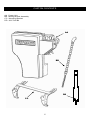
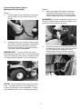
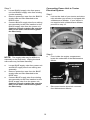
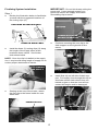
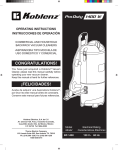
Operator’s Manual
RIDER COOLING SYSTEM
Model No. 132.24607
CAUTION:
Before using this product, read
this manual and follow all Safety
Rules and Operating Instructions.
IMPORTANT: For replacement parts or
assembly questions call 800-320-MIST.
Sears, Roebuck and Co., Hoffman Estates, IL 60179 U.S.A
www.craftsman.com
•
•
•
•
•
Safety
Assembly
Operation
Maintenance
Troubleshooting
TABLE OF CONTENTS
SAFETY RULES………………………………
HARDWARE CONTENTS…………………
CARTON CONTENTS……………………….
ASSEMBLY……………………………………
OPERATION………………………………….
MAINTENANCE…………………………… 16
17
STORAGE………………………………
TROUBLESHOOTING……………………. 17
PARTS ORDERING/SEVICE…… Back Page
2
3
4
5
14
SAFETY
•
•
•
•
•
Always wear safety glasses when operating or installing your riding cooling system.
Install rider cooling system on your tractor
only when engine is cool. Allow engine to
cool if recently operated before attempting
to install. Installation requires access to
the engine compartment of your tractor.
Disconnect the negative (-) battery cable
from your battery prior to installing the
rider cooling system on your tractor.
In the event that another liquid other than
DRINKING WATER is used to fill the water
tank, immediately drain the contents of the
tank and contact customer service regarding steps to take to help determine the
usability of your system.
This rider cooling system is designed to
operate with DRINKING WATER ONLY.
City water supply, bottled water, and other
sources deemed suitable for human consumption will ensure optimal functionality
of the system throughout maintenance
intervals.
In the event that gasoline is mistakenly
added to the water tank, immediately stop
using the cooling system and contact customer service regarding the best way to
dispose of your system.
•
WARRANTY
ONE YEAR FULL WARRANTY
If this Craftsman product fails due to a defect in material or workmanship within one year from the
date of purchase, return it to any Sears store or other Craftsman outlet in the United States for free
replacement.
This warranty does not include the air or water filter, which are expendable parts that can wear out
from normal use within the warranty period.
This warranty applies for only 90 days if this product is ever used for commercial or rental purposes.
This warranty gives you specific legal rights, and you may also have other rights which vary from
state to state.
Sears, Roebuck and Co., Hoffman Estates, IL 60179
The model number and serial number can be found
on the label attached to the back of the power unit.
MODEL NUMBER:
SERIAL NUMBER:
You should record both the serial numbers and the
date of purchase and keep in a safe place for future
reference.
2
DATE OF PURCHASE:
132.24607
HARDWARE PACKAGE CONTENTS
A
F
H
B
G
C
I
D
E
J
REF.
QTY.
DESCRIPTION
A
2
Hex Bolt, 5/16”-18 x1-1/4”
B
2
Flat Washer, 7/8” OD
C
4
Cap Screw, 5/16-18” x 3/4”
D
8
Flat Washer, 5/8” OD
E
4
Nylock Nut, 5/16”-18
F
2
Dash Adapter Nuts
G
4
Routing Clips
H
1
Rubber Washer
I
1
Dash Adapter Spacer
J
4
Cable Ties
3
CARTON CONTENTS
AA.
BB.
CC.
DD.
Power Unit
Misting Nozzle Assembly
Mounting Bracket
9/16” Drill Bit
AA
BB
DD
CC
4
ASSEMBLY
•
Tools Required
½” Socket Wrench w/ Extension
Allen Wrenches
Power Drill
Adjustable Wrench
With bracket in place, assemble springs
to tractor using the new 5/16” x 1-1/4”
bolts (A) and 5/16” flat washers (B) supplied with the cooling system. Tighten
using moderate force. Do not over
tighten.
Mounting Power Unit To Tractor
NOTE: If there is a 2 or 3 bin bagger installed
on your tractor, you will need to remove the
bagger from the tractor before proceeding.
Leave the bagger bracket mounted to the vehicle. After cooling system is installed, bagger
may be reinstalled.
Step 1
•
Raise the tractor seat and remove the seat
springs using a ½” socket wrench. Set
aside springs. (Save bolts in the event you
want to reinstall seat springs without the
bracket.)
Step 2
•
With tractor seat still in the raised position, slide power unit in-between the ears
of the mounting bracket. Power unit
should rest on alignment tabs.
ALIGNMENT
TAB
•
Install mounting bracket (CC) by placing
hooks of bracket under lip of tractor body.
Rotate into position. Slots in bracket
should line up with seat spring mounting
locations.
•
5
Align holes, and attach power unit to
mounting bracket using four cap screws
(C), eight washers (D), and four nylock
nuts (E).
•
Mounting Misting Nozzle Assembly to
Tractor
Once all bolts have been installed, tighten
all nuts using allen wrench and socket
on both bolts and nuts.
The rider cooling system misting assembly is
designed to be installed on the tractor’s dash.
Some tractors come equipped with rider cooling
system mounting locations.
If you do not have a dash with the included
mounting locations proceed to STEP 3b.
LEFT MOUNTING
LOCATION
•
Confirm the installation of all four screws
(A) that hold the power unit (AA) to the
mounting bracket (CC).
WARNING: Debris that may enter the supply
tubes of the climate control system can cause
undesirable performance results. Use care
completing the remainder of the installation to
ensure optimal cooling effectiveness.
Step 1a (Tractors w/ mounting locations)
6
•
Remove dust cap from rider’s left mounting location. A screwdriver may be
needed to pry dust cap from dash.
•
Open tractor hood and ensure that no
wires or cables are located at the bottom
of the mounting location. If wires or cables
are present, temporarily clear the area by
securing them safely away from mounting
location using a supplied cable tie (J).
•
Step 2
Using supplied 9/16” drill bit (DD), drill hole
through the dash at the bottom of the
mounting location. Use caution not to
damage anything in the engine compartment while drilling hole.
•
Install rubber washer (H ) onto the misting
arm assembly (BB), by sliding over hoses
and threaded section until seated against
mounting flange.
DRILL BIT
(DD)
RUBBER
WASHER (H)
•
Proceed to Step 2.
•
Feed supply lines of nozzle holder assembly (BB) through hole drilled in step 1 .
•
From inside the engine compartment, pull
supply lines through hole until the flange of
the misting nozzle assembly (BB) is
seated on the surface of the dash.
Threaded portion of adapter should now
extend into the engine compartment at
mounting location.
Step 1b (Tractors w/o mounting locations)
•
•
•
•
•
•
•
Open tractor hood and ensure that no
wires or cables are located at the bottom
of potential mounting locations. If wires or
cables are present, temporarily clear the
area by securing them safely away from
mounting location using a supplied cable
tie (J).
Evaluate dash for best location to mount
misting arm. Ensure that the chosen location will not limit the functionality of the
tractor or interfere with closing of the hood.
Mark desired location.
Prior to drilling, take precautions to protect
engine compartment from drill shavings.
Using supplied 9/16” drill bit (DD), drill hole
through the dash at the desired mounting
location. Use caution not to damage
anything in the engine compartment
while drilling hole.
Remove drill shavings and clean area
surrounding mounting location.
Proceed to Step 2.
7
Step 3
•
IMPORTANT: If you have not already done
so, you must disconnect the negative (-) terminal of the battery before completing the next
steps.
•
NOTE: If a hole was drilled in a dash not
equipped with mounting locations, (Step 1b)
you will need to slide the dash adapter spacer
(I) over hoses of the misting arm assembly (BB)
prior to proceeding.
•
Slide one dash adapter nut (F) over supply
lines and thread onto adapter until seated
on the bottom surface of dash. Tighten
using moderate force. Do not over
tighten.
8
Repeat with the remaining dash adapter
nut (F) until seated on bottom surface of
the nut already installed. Use care to
ONLY tighten second nut. Tighten using
moderate force. Do not over tighten.
The assembly is now secure to the dash of
the tractor.
Connecting Power Unit to
Misting Arm Assembly
Step 2
•
Step 1
•
•
Locate supply lines and power connector
at the power unit (AA) and uncoil to full
length.
When the supply lines have exited the
underside of the tractor body, feed the
supply lines and power connector along
tractor chassis into engine compartment.
WARNING: Engine components may be hot.
Exercise caution when working in engine compartment to avoid personal injury.
Starting at the rear of tractor, feed supply
lines and connector assembly underneath
tractor body along right side of chassis
using care to avoid any potential interference with tractor functionality.
•
IMPORTANT: To ensure lines will not be
damaged during tractor use, it is recommended
that you follow the exact path of existing electrical supply lines installed on your lawn tractor.
NOTE: Do not install routing clips (G) at this
time. The lines are only run to make the connection at this point in the installation. Finalizing installation will occur in subsequent steps.
9
Continue to feed lines through the engine
compartment to the other side of the tractor. Ensure that the supply lines are
routed safely away from the engine by
routing behind existing cables and wires.
Connecting Power Unit to Tractor
Electrical System
Step 3
•
•
•
Locate BLACK supply tube from power
unit and BLACK supply tube from misting
nozzle assembly.
Remove protective caps from the BLACK
supply tube and filter attached to the
BLACK tube.
Connect BLACK supply tube from misting
arm assembly to the filter installed on the
BLACK supply tube from the power unit.
Continue to push supply tube over the
barb on the filter until it rests against
the filter body.
Step 1
•
Look on the dash of your tractor and determine whether your tractor is equipped with
a Maintenance Minder. If your tractor is
not supplied with a Maintenance Minder,
proceed to step 12.
MAINTENANCE
MINDER
Step 2
•
NOTE: The supply tube may be difficult to
assembly to the filter body. Wiping the barb
with water may facilitate assembly.
•
•
•
From inside the engine compartment,
locate the underside of the Maintenance
Minder.
MAINTENANCE
MINDER
Locate BLUE supply tube from power unit
and BLUE supply tube from misting arm
assembly.
Remove protective caps from the BLUE
supply tube and filter attached to the
BLUE tube.
Connect BLUE supply tube from misting
arm assembly to the filter installed on the
BLUE supply tube from the power unit.
Continue to push supply tube over the
barb on the filter until it rests against
the filter body.
TRACTOR
CONNECTOR
•
10
Disconnect tractor electrical connector
from Maintenance Minder.
Step 3
Step 4
•
•
Connect power unit’s female connector to
Maintenance Minder.
NOTE: The tractor power supply connector
will resemble the female connector supplied
with the power unit. It will have blue and black
wires attached to it.
POWER UNIT
FEMALE
CONNECTOR
•
From inside the engine compartment,
locate tractor power supply connector.
TYPICAL LOCATION
OF TRACTOR
CONNECTOR
Connect power unit male connector to
tractor electrical connector just removed
from Maintenance Minder in Step 10.
TRACTOR
CONNECTOR
•
Connect power unit’s male connector to
tractor connector until fully engaged.
Locking tab will hold connection together.
POWER UNIT
MALE
CONNECTOR
•
Proceed to Finalizing System Installation.
POWER UNIT
MALE
CONNECTOR
•
11
Verify all connections have been made
and proceed to the next steps.
Finalizing System Installation
IMPORTANT: Do not kink hoses exiting the
power unit. Leave enough excess for a
generous bend in the supply lines when
assembling clip to tractor.
Step 1
•
Review the illustration below to familiarize
yourself with the suggested locations of
the routing clips (G)
EACH SIDE OF DASH SUPPORT
PROPER SLACK FOR
OPTIMAL OPERATION
•
FRAME IN WHEEL WELL
•
Install the three (3) routing clips (G) along
the length of the supply tubes at the
locations shown above. See further
instructions below.
Continue mounting the next clip to the
dash support on the right side of the
tractor .
NOTE: Once the clip is installed to the supply
line, it may be slid along length of supply line to
ensure proper attachment to tractor.
CLIP OPENING
FOR SUPPLY
INSTALLED CLIP
•
•
Install final clip on left side of dash support. Pull supply lines through this clip to
eliminate excess slack where lines run
behind engine so that the lines will not
contact hot engine and be damaged.
Starting at the rear of the tractor, attach
the first clip to the frame inside the rear
wheel well.
INSTALLED CLIP
INSTALLED CLIP
12
Checklist
Step 2
•
Using a supplied cable tie (J) organize any
excess length of supply tubes and stow
behind battery (or along fuel tank if
equipped). Secure supply tubes to
electrical supply lines of tractor at
convenient locations to prevent line
damage during tractor operation.
Before you operate your rider cooling
system, please review the following
checklist to ensure that you will obtain the
best performance from your system.
•
•
•
•
•
•
Using remaining cable ties (J) secure
supply tubes to tractor frame along length
under tractor body.
•
•
IMPORTANT: Use care not to over tighten
cable ties (J) and pinch supply lines as system
will not function properly. Cable ties are used
as a means to route lines safely away from heat
and possible pinch points during tractor operation. Following paths of your tractor’s electrical
supply lines ensures the best possible results.
•
•
Reconnect negative (-) battery terminal to
tractor electrical system.
Make sure all assembly instructions have
been completed with all bolts and nuts
tightened.
Make sure hose connections at the filters
have been made and are fully engaged.
Make sure electrical connection has been
made and is secure.
Check routing of supply lines and make
sure they do not interfere with pedals,
pulleys, or belts.
Check supply lines in engine compartment
and ensure they are safely routed away
from the engine.
Check the supply lines as they exit the
power unit and ensure the bend is
sufficient and does not kink the hoses.
Check the misting nozzle assembly to
ensure it does not interfere with tractor
controls.
Turn tractor key to “ON” position and turn
cooling system power unit on.
• Confirm that the cooling system
pump starts.
• Confirm the flow of air from the
cooling nozzle.
• Open the tractor hood and
ensure that filter connections
are maintained.
You are now ready to enjoy the benefits of your
cooling system .
Proceed to the OPERATION section of this
manual to begin using.
13
OPERATION
KNOW YOUR RIDER COOLING SYSTEM
Read this owner’s manual before operating.
Compare the illustration below with your rider cooling system to familiarize yourself with the various
features and their locations.
POWER SWITCH Controls the power
to the system’s pump.
FILL CAP Used to seal the water tank.
Removal permits the filling of the water
tank.
BASKET FILTER (Located under fill
cap) Catches large particulate matter
to ensure long life of the inline filters.
ADJUSTMENT VALVE Controls the
water flow to the nozzle.
POWER UNIT The power center of the
system.
DRAIN PLUG Allows the user to drain
the water tank.
BEFORE STARTING
•
•
•
•
Use end of assembly checklist to verify
that all instructions have been properly
completed.
Remove fill cap on power unit and fill with
DRINKING WATER through the basket
filter until tank is filled to approximately 1”
below the bottom of the basket filter.
Add 5 drops of household bleach to the
water tank before the first use and every
fourth use or once a month (whichever
comes first) after that.
Replace cap and hand tighten. This is a
pressurized system and requires that
the cap is sealed.
IMPORTANT: This unit is designed to operate with DRINKING WATER ONLY.
IMPORTANT: Do not operate rider cooling
system with tractor headlights in the ON position. Excessive load on tractor’s battery will
result in premature drainage.
NOTE: In event that the tank is overfilled, you
may experience water streaming from the
nozzle. If this occurs, drain excess water from
tank and run unit until desired mist is achieved
prior to operating tractor.
14
HOW TO START YOUR RIDER
COOLING SYSTEM
•
OPERATING TIPS
•
With the tractor key in “ON” position,
toggle power switch on unit to “ON” position.
•
NOTE: It is normal to experience a delay from
the time the system is turned on to the delivery of mist from the nozzle. If this exceeds 2
minutes, refer to the troubleshooting section.
•
HOW TO STOP YOUR RIDER
COOLING SYSTEM
•
Toggle power switch on unit to “OFF”
position.
NOTE: The system will continue to mist after
the system is turned off. The system will stop
misting after the water and air lines have been
cleared.
HOW TO REFILL YOUR RIDER
COOLING SYSTEM
•
•
•
•
Switch power switch on power unit to the
“OFF” position.
Allow system to vent. System is ready
to fill when air can no longer be heard
coming from misting head.
Remove fill cap on power unit and fill
through basket filter with DRINKING
WATER ONLY .
Replace cap and hand tighten.
ADJUSTING MIST DENSITY
•
•
•
•
To optimize the cooling effectiveness of
the system, the adjustment valve offers
unlimited variation of mist density from
closed to fully open.
To increase the mist density, turn valve
counterclockwise.
To decrease the mist density, turn valve
clockwise.
Once you are satisfied with the setting of
your mist density, use the locking nut on
the adjustment valve to save your setting.
15
Never use any liquid other than
DRINKING WATER in the system.
For dry climates, increasing the water
flow will provide maximum cooling results. In humid climates, a reduced water
flow is recommended.
Adjust the misting nozzle direction to
maximize contact with exposed skin
during operation.
MAINTENANCE
CUSTOMER RESPONSIBILITIES
•
Read and follow the maintenance schedule and the maintenance procedures listed in this
section.
EMPTYING WATER TANK
REPLACING FILTERS
•
The filters have been designed to provide
optimal system performance by catching any
debris that may enter the supply lines throughout use. Annual replacement of both the air
and water inline filters ensures the life of your
system.
• Open tractor hood and locate the inline
filters on the water (blue) supply line.
• Cut water (blue) supply line at each end
of filter body.
• Dispose of filter.
•
•
•
•
Place container under drain valve, or
have tractor on surface where water can
be drained to.
Remove drain plug by turning counterclockwise.
Loosen fill cap.
Allow tank to drain completely.
Replace drain plug and hand tighten
turning clockwise.
CLEANING BASKET FILTER
•
•
•
•
Remove fill cap and remove basket filter.
Rinse debris from filter with running
water.
Replace basket filter and fill cap.
Remove filter from package and orient
directional arrow so that the flow direction
is towards the misting assembly.
(B)
CONDITIONING WATER TANK
Conditioning the water tank ensures that the
cooling system will operate at optimal levels
throughout the life of the system. It is suggested that the tank be conditioned at an interval of every 4th filling or once a month; whichever comes first.
• Completely drain water tank. (See Emptying Water Tank)
• Fill tank with DRINKING WATER. Be
sure to always fill tank with basket filter in
place.
• Add 5 drops of household bleach to water tank.
• Replace cap and hand tighten.
•
•
(A)
•
•
Run system for 5 minutes with increased
water flow.
The system is conditioned and ready for
operation.
•
16
Push supply line from power unit over
filter barb near base of arrow (A) until
seated against filter body.
Push supply line from misting nozzle over
filter barb at arrowhead (B) until seated
against filter body.
Repeat steps for air (black) supply lines.
STORAGE
•
•
•
•
Empty water tank completely, replace
cap, and run system to evacuate all water in supply lines.
Store misting nozzle assembly by folding
over dash of tractor.
Ensure the power switch on the power
unit is in the “OFF” position.
•
Clean debris from venting on rear of
power unit.
Clean the power unit thoroughly with mild
soap and water.
TROUBLESHOOTING
PROBLEM
CAUSE
CORRECTION
Pump Not
Running
1.Switch in OFF Position
2.Tractor Key in OFF Position
1.Toggle Switch to ON Position
2.Tractor Key to ON Position
Unit not Misting
1.Water tank is empty
2.Adjustment valve closed
3.Fill cap not sealed
4.Drain plug not sealed
5.Water filter needs replaced
6.Basket filter missing
1.Fill tank with DRINKING WATER
2.Open adjustment valve
3.Properly seat fill cap
4.Properly seat drain plug
5.Replace water filter
6.Install basket filter
Water streaming from
Misting Nozzle
1.Water in air supply lines
(Tank Overfull)
2.Adjustment valve setting
3.Air filter needs replaced
1.Drain tank and run system until
only air is emitted from nozzle
2.Close adjustment valve
3.Replace air filter
Inconsistent Misting
1.Adjustment valve changing
position
1.Adjust valve to desired mist density and tighten locking nut against
power unit housing
Water Dripping from
Drain Plug
1.Drain plug not seated
2.Drain plug seal is missing or
damaged
1.Properly seat drain plug
2.Replace drain plug seal
17
NOTES:
18
NOTES:
19
20