1
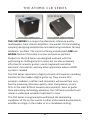
CLR SERIES
OWNERS MANUAL
ACLR-AC
ACLR-AW
ACLR-PC
ACLR-PW
ACTIVE CAB
ACTIVE WEDGE
PASSIVE CAB
PASSIVE WEDGE
THE WORLD’S FIRST AND LEADING COMPANY
DESIGNING AMPLIFICATION AND MONITORING SOLUTIONS
FOR AMP MODELERS / PROFILERS
www.atomicamps.com
WARNING!
TO PREVENT FIRE OR SHOCK HAZARD,
DO NOT EXPOSE THIS UNIT TO RAIN
OR MOISTURE.
The Atomic CLR is designed for use
as a floor wedge or pole-mounted
PA speaker in portable sound
reinforcement applications.
It is not intended for overhead suspension.
Use in that manner is unauthorized and may
cause injury or death.
NO USER SERVICABLE PARTS INSIDE,
REFER SERVICING TO QUALIFIED
PERSONNEL ONLY.
SERVICE BY PERSONS OTHER THAN
ATOMIC AUTHORIZED SERVICE
TECHNICIANS MAY VOID WARRANTY.
THIS UNIT MUST BE
EARTH GROUNDED.
Atomic Amplifiers and Atomic CLR Series are trademarks of Atomic Amplifiers LLC. Any
other product names, trademarks or names are the property of their respective owners
which are in no way associated with or affiliated with Atomic Amplifiers LLC
© 2013 Atomic Amplifiers LLC. All rights reserved.
Atomic Amplifiers LLC • [email protected] • www.atomicamps.com
REACTOR SERIES
USER MANUAL
T a b le o f contents
2
The CLR Series
3
Summary of Components
4
Panel Diagrams
5 - 6Features & Instructions
7
Specifications
8Warranty
1

T h e atomic C L R S E R I E S
THE CLR SERIES is a range of professional, reference quality
loudspeakers from, Atomic Amplifiers, the world’s first and leading
company designing amplification and monitoring solutions for amp
modelers / profilers. The current offering includes both CAB and
WEDGE formats that come in active and passive versions.
Products in the CLR Series are designed and built with the
performing or studio guitarist in mind, but are also extremely
effective for acoustic guitars, vocals, keyboards and other
electronic instruments, and any other application where a FRFR
system is needed.
The CLR Series represents a highly accurate and superior-sounding
solution for the modern digital guitar rig. They ensure that
preamps, modelers, profilers and simulators will sound their very
best by producing reference-quality sonic transparency at rock
SPLs in the most difficult acoustic environments. Even as guitar
tone processing technology advances, the CLR Series products will
remain a viable and valuable investment in tone.
The CLR Series is engineered to withstand the demanding
conditions of life on the road or in other professional environments,
whether on stage, in the studio, or in a standalone setting.
2
SYSTEM DESCRIPTION
The Atomic CLR is a two-way coincident loudspeaker consisting of
a heavy-duty, horn-loaded 12” cone transducer for low frequencies
and a high-output, 1”-exit compression driver with a 1.75” voice coil
driving a constant-directivity type horn for high frequencies. The
enclosure is constructed of 12-ply, void-free plywood throughout,
with internal structural details that serve both to form the lowfrequency horn shape and to add substantial structural rigidity.
Non-powered versions of the CLR incorporate a heavy-duty passive
crossover designed to optimize amplitude response and preserve
the integrity of transient signals. Powered versions include two
independent channels of power amplification - one each for low
and high frequencies - and a line-level active crossover that
employs digital signal processing. The power amplifier topology is
a patented, high-performance variation on Class D that has found
use in a number of expensive, audiophile-quality loudspeakers.
The DSP filtering is designed to optimize both amplitude and
transient response and is equipped with special features designed
to minimize the chances of driver damage due to operation at
excessive levels.
Active CLRs provide user-selectable presets for three common
acoustic boundary conditions: free-field, tilt, and backline. The
freefield setting is optimized for use when the speaker is elevated
off the floor on a pole or stand; the tilt setting is optimized for use
as a floor wedge, with the speaker on the floor aimed up at the
player; and the backline setting is optimized for placement of the
speaker on the floor and aimed horizontally, as is common for guitar
amp usage. There is also a switchable 120-Hz highpass filter for
use with a subwoofer or for removal of unwanted low frequencies.
Refer to the panel diagram for more features.
3
A cti v e C a b and W ed g e C ontrol Panel
1
Heat Sink
2
Input 1 Level
3
9
4
Input 2 Level
11
10
8
Input 2
Input 1
Clip LED
5
13
12
Preset Switch
6
Speaker Limit
Indicator
Link Select
14
Link
Master Level
7
Power
Switch
Sub
15
IEC Power Inlet
Input 2
Clip LED
Input 1
P A S S I V E C a b and W ed g e C ontrol Panel
1
Input
2
Thru
4
Active Cab and Wedge Panel Explanations

1 Heat Sink – Allows the CLR Series to be fanless and “studio quiet”. It
1. keeps amp modules and power supply cool by drawing heat from them
and dissipating it into the open air. Please note: The heat sink will
get warm to the touch while the amp is powered “on” even when
the amp is at idle. This is normal and is well within regulated
operating guidelines.
2
2. Input
1 Level – Adjusts the input signal level to the amplifier.
3
4. Input
2 Level - Adjusts the input signal level to the amplifier.
4 Preset Switch – Adjusts the frequency response of the amplifier to
5. accommodate 3 different cabinet orientations while maintaining a flat
response. The presets are: “FF” = Free Field – for when the cabinets are
elevated off the floor like on a chair, pole mount or stand, “Tilt” – for
when the cabinet is set up in the wedge position on the floor and “BL”
– for when the cabinet is set up like a traditional guitar setup on the
floor.
5 Speaker Limit Indicator – Flashes red when speaker is approaching
6. it’s operating limit. An internal safety function stops the amp from
driving the speaker harder. Please note: The speaker limit indicator will
flash in advance of the threshold. Only when it is nearly constantly lit
red will the safety function come into play.
6 Master Level – Controls the over volume of the CLR
7. 7 Sub – When in the “on” position this switch attenuate the low end of
8. the system to accommodate use with an external sub woofer.
8
3. Power
Switch – Switches the amplifier “on” or “off”.
9
9. Input
1 – ¼” / XLR Combo input jack for the amplifier.
10
1
Input 1 Clip LED - Flashes red to alert that Input 1 is being clipped.
11
1
Input 2 - ¼” / XLR Combo input jack for the amplifier.
12
1
Input 2 Clip LED - Flashes red to alert that Input 2 is being clipped.
13
1
L
ink Select – Selects what inputs get sent to the Link Output – “1”
Input 1, “2” Input 2 and “X” a mix of Input 1 and 2. The level controls
only come into play in “X” or Mix mode otherwise it sends through unity
gain from the selected channel.
14
1
L
ink Output - A pre eq, buffered pass through that takes signal
directly from the analog front end to wherever you need to send it.
15
1
I EC Power Inlet - Connect the supplied AC line cord to provide power
to the amp.
5
PASSIVE Cab and Wedge Panel Explanations

1 Input – ¼” / Speakon Combo input jack for the speaker system.
1. 2
2. Thru
– ¼” / Speakon Combo pass though to send signal to
another system.
Gain Structure Setup for Active Speakers
Optimizing gain structure is an important step in minimizing noise and
preventing signal overload (clipping). There are three level controls on
the panel of active CLR speakers. After connecting all the devices in your
signal chain and powering up (remember CLR last on, first off), follow the
procedure below to insure optimal gain structure.
1 Set the Master and both Input level controls to their lowest
1. (CCW) settings.
2 If you will be using two input signals, perform this step with the one
2. you expect to be louder. (Note: You will hear little or no sound during
this step.) Apply the hottest (loudest) signal you expect to generate.
Increase the Input level control for that channel until you see the LED
adjacent to that input connector light up. Turn down the level until the
LED goes out and never lights.
3 Adjust the Master level for the desired volume and the second Input
3. level (if used) for the desired mix. There is no need to adjust the
Input levels beyond this point. The amp has the ability to reach its
maximum output level with the input level set as prescribed above.
Overdriving the input by setting the input level too high will result
in audible clipping.
Passive Cab and Wedge Operating Instructions
Passive CLRs are equipped with two combo connectors (Neutrik Speakon
and 1/4” jack). These connectors are wired in parallel and are intended
to enable the user to “daisy chain” a second CLR to a single power
amplifier. Keep in mind that the combined impedance of two CLRs in
this configuration is 4 ohms and make certain that the power amplifier
is rated to drive this impedance. Caution: under no circumstances should
the additional connector ever be connected to a second power amplifier.
Doing so could result in damage to one or both power amplifiers and to
the speaker(s).
6
S peci f ication
Frequency
Response
Active: 70Hz-18kHz, +/- 2.5 dB
Passive: 70Hz-18kHz, +/- 2.5 dB
Max Continuous
SPL
Active: 120 dB
Passive: 120 dB
Maximum Peak
SPL
Active: 130 dB
Passive: 130 dB
Amplifier Power
Active: 500W Bi-amped
Passive: N/A
Recommended
Maximum
Amplifier Size
Active: N/A
Passive: 500W
Power
Active: N
orth American Model: 100-120VAC Input,
European Model: 220-240VAC Input
Passive: N/A
Directivity
Active: 90 degrees H x 90 degrees V, average from 650Hz and up
Passive: 90 degrees H x 90 degrees V, average from 650Hz and up
Sensitivity
Active:N/A
Passive: 100dB, 1W @ 1M
Impedance
Active: 20kohms, 10kohms unbalanced
Passive: 8 ohms
Crossover
Active: Active crossover
Passive: Passive crossover
Drivers
Active: (1x) Custom 250w 1x12”, (1x) 90w 1” HF Compression Driver
Passive: (1x) Custom 250w 1x12”, (1x) 90w 1” HF Compression Driver
D imensions & W ei g ht :
Active Wedge (ACLR-AW):................................................17 5/8” x 17 5/8” x 15 3/4”, 45lbs
Active Cab (ACLR-AC):.......................................................17 5/8” x 17 5/8” x 13 5/8”, 46lbs
Passive Wedge (ACLR-PW):.............................................17 5/8” x 17 5/8” x 15 3/4”, 44lbs
Passive Cab (ACLR-PC):....................................................17 5/8” x 17 5/8” x 13 5/8”, 45lbs
7
Response Data

On Axis Amplitude Response
Freefield response with test mic at 2 meters
Normalized Off Axis Responses
Off axis responses taken at 10-degree intervals normalized to on-axis response
8
WARRANTY
Atomic Amplifiers warrants to the original purchaser that this product will be free of defects in material
and workmanship for a period of 1 year from the original date of purchase. It is understood that Atomic
Amplifiers reserves the rights to inspect any warranty part prior replacing or repairing them to insure that
their defect is not a result of user error. These warranties are subject to the conditions, exclusions, and
limitations hereinafter set forth. This limited warranty is transferable and is valid only when accompanied
by a copy of the original sales receipt or packing slip with legible purchase date, purchase price, and
when product is purchased from an authorized dealer in the and must be returned to the same for any
warranty services required. All exported products are subject to warranty and services to be specified
and provided by the authorized distribution center for each country or region. Excluded from this
warranty are defects caused by wear and tear, accident, misuse, neglect, failure to follow all operating
instructions (including the OVERPOWERING of speakers), alterations and modifications, or act of nature.
Such determinations will be made by Atomic Amplifiers. This limited warranty is also void if: the original
retail purchase is not made directly from the company or an Authorized ATOMIC AMPLIFIERS’ dealer,
or if repairs, alterations, or modifications are performed by anyone other than Atomic Amplifiers or an
Atomic Amplifiers Authorized Service Center, or if the original serial number affixed to the product is
altered, defaced, or removed.
All parts costs for repairs covered under this limited warranty will be borne by Atomic Amplifiers so
long as the repairs have been requested within the applicable warranty periods described above. It is
understood that all repair charges and costs incurred by Atomic Amplifiers for all periods following the
applicable warranty period will be borne and paid for by the purchaser. All labor costs incurred by Atomic
Amplifiers for repairs covered under this limited warranty will be borne and paid for by Atomic Amplifiers
within the applicable warranty period according to rate schedules established by Atomic Amplifiers. All
labor costs and expenses above these rates will not be the responsibility of Atomic Amplifiers.
Atomic Amplifiers, or an Atomic Amplifiers Authorized Service Center MUST do all warranty services.
Transportation charges involved in warranty services are the sole responsibility of the purchaser.
A copy of the original sales receipt or packing slip must accompany all products being presented to an
Atomic Amplifiers Authorized Service Center for warranty service. All products being returned to Atomic
Amplifiers for warranty service must be accompanied by a copy of the original sales receipt or packing
slip, a detailed description as to needed repairs, and an Atomic Amplifiers Return Authorization number.
Atomic Amplifiers reserves the right to repair or replace the affected piece of equipment at their option
but it is understood that repair or replacement as provided under this limited warranty is the sole and
exclusive remedy to the purchaser for defective or non-conforming products. Atomic Amplifiers will not
be held liable for any incidental consequential, special, punitive, or exemplary damages resulting from
any defect or failure of this product other than the repair of the Atomic Amplifiers product subject to the
terms of this limited warranty. Any product repaired or replaced under this limited warranty will, itself,
be warranted only for the remainder of the limited warranty period of the original product being repaired
or replaced. Products used for dealer rental purposes shall be warranted from the date of the original
invoice to dealer and if sold will be warranted only for the remainder of the limited warranty period of
the original product. This warranty gives you specific legal rights, and you may have other rights which
vary from state to state, and province to province, and to the extent required by law, any limited warranty
shall be limited to the duration of this limited written warranty.
OTHER THAN AS STATED ABOVE, ATOMIC AMPLIFIERS MAKES NO WARRANTIES EITHER WRITTEN,
EXPRESSED, OR IMPLIED WITH RESPECT TO THE PRODUCT. THIS WARRANTY IS EXCLUSIVE,
AND ATOMIC AMPLIFIERS MAKES NO OTHER WARRANTY, EXPRESSED OR IMPLIED, INCLUDING
IMPLIED WARRANTIES OR MERCHANTABILITY OR FITNESS FOR ANY PARTICULAR PURPOSE, ALL
OF WHICH WARRANTIES ARE HEREBY BEING DISCLAIMED.
9
Atomic Amplifiers LLC
469 Derby Milford Road, Orange, CT 06477
(646) 201-9543 [tel]
[email protected]
www.atomicamps.com
www.atomicamps.com