1
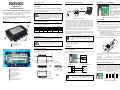
C-BOX 100
Instruction Manual
SAFETY PRECAUTIONS
ELECTRICAL CONNECTIONS AND SETUP
ATTENTION: READ THIS INFORMATION BEFORE INSTALLING THE PRODUCT
The following figure shows the typical layout.
This product is intended to be installed by Qualified Personnel only.
A 9-pin connector placed inside the C-BOX 100 facilitates connection
between an external PC and the auxiliary serial interface of the scanner
for configuration or data monitoring.
GENERAL VIEW
CAUTION
The C-BOX 100 can be connected to the following readers through the
25-pin connector illustrated in Figure A.
3
Linear Scanners
DS2100A
*DS1100
DS2400A
*DS2200
DS4600A
2D Readers/Cameras
DS6XXX
MATRIX-1XXX
DX6XXX
MATRIX-2XXX
DV9500
DS8100A
* It is necessary to use 10-30 V versions for DS1100 and DS2200
scanners.
To install the C-BOX 100 or during normal maintenance, it is necessary
to open it by unscrewing the four cover screws:
2
Figure A
The C-BOX 100 must be disconnected from the
power supply during this operation.
1 25-pin scanner connector
2 Compression connectors
3 Cover screws (4)
System Cables
Figure 5– Scanner Power Solder Bridge
Figure 2 – System Layout
The dotted line in the figure refers to an optional (temporary) hardware
configuration in which a portable PC can be quickly connected to the CBOX 100 (and consequently to the scanner auxiliary interface) through
the internal 9-pin connector. This allows monitoring of the data
transmitted by the scanner or configuration through the utility program
(see the scanner Installation Manual for more details). The scanner
auxiliary interface signals are also available on the internal spring clamp
connectors.
After making system cabling and switch settings, connect the scanner to
the 25-pin connector on the left side of the C-BOX 100 housing.
Switch ON the C-BOX 100 power switch (see Figure 3). The correct
polarity of the power connection is signaled by the green LED, while the
red LED turns on in case of wrong polarity.
7
The diagram below gives the overall dimensions of the C-BOX 100 and
may be used for its installation.
21
40
2
5
[0.20]
• Using a device such as a screwdriver, push down on the lever
directly next to the clamp (see Figure 6).
• Insert the wire into the clamp and release the lever.
The wire will now be held in the spring clamp.
40
[1.57]
90
[3.54]
161
[6.34]
Figure 1 - Overall Dimensions
Figure 6 - System Cable Connections
All positions:
OFF
Figure 3 - Power Switch ON/OFF Positions
114.5
[4.51]
7 Auxiliary port connector
8 OM4000 jumpers
9 Termination resistance switch
10 Spring clamp terminal blocks
89.8
[3.54]
USER INTERFACE
C-BOX 100
Figure B
6 Scanner selection switch
• Prepare the individual wires of the system cables by stripping
the insulation back approximately 1 cm.
The wiring used can be solid or stranded but must meet the following
specifications.
66
[2.60]
150
[5.91]
10
5 Power Polarity Error LED (red)
4) To connect the power and input/output signals:
24 - 16 AWG
0.2 - 1.5 mm²
The C-BOX 100 spring clamp connector pinouts are indicated in the
Pinout tables.
ON
5
[0.20]
4 Power on LED (green)
3) Unscrew the compression connectors and pass all the system
cables through them into the C-BOX 100 housing.
The power switch (see Figure 3) switches the power supply ON or OFF
for both the C-BOX 100 and the connected scanner.
9
12
[0.47]
20
2 Chassis grounding selector
3 INT-30 power connector for 20 mA C.L.
2) Verify that the C-BOX 100 power switch is off (see Figure 3).
Power is supplied to the C-BOX 100 through the pins provided on the
spring clamp connector.
S1
8
1
1 Power switch (ON/OFF)
1) Open the C-BOX 100 by unscrewing the 4 cover screws.
After system functioning has been verified, close the C-BOX 100 using
the 4 cover screws making sure the rubber seal is fitted correctly
between the parts of the housing.
Ø3.5
[Ø0.14]
1
The connection and wiring procedure for C-BOX 100 is described as
follows:
POWER SUPPLY
12
[0.47]
6
NOTE
Power is supplied to the connected scanner (25-pin
connector only) through an electronic circuit which:
limits the inrush current; provides short circuit
protection and over current protection (automatic
retry).
SYSTEM WIRING
CAUTION
MECHANICAL INSTALLATION
5
This is useful for example, to pass
power to connected accessories
such as Encoder and Presence
Sensor from DX8200A VAC models
or other scanner layouts. See the
relative scanner Reference Manual
for details.
Scanner Configuration PC
OPENING THE DEVICE
1
Scanner
Auxiliary
Interface
SCANNER
The overall value of power consumption of the
system (C-BOX 100 + scanner) is given by adding
the scanner power consumption to that of the C-BOX
100. Refer to the manual of the connected scanner
for details about minimum/maximum supply voltage
and power consumption.
SUPPORTED SCANNER MODELS
C-BOX 100
C-BOX 100
This device is intended to be supplied by a UL Listed NEC Class 2 power
source, rated 10-30V, minimum 0.50A.
System cabling is made through spring clamp terminal blocks inside the
C-BOX 100 while the scanner is connected to the C-BOX 100 through a
25-pin connector placed on the left side of the housing.
4
In order for C-BOX 100 to accept
power from the scanner through the
25-pin connector, a solder bridge
must be made at the two pads
indicated in Figure 5.
POWER SUPPLY
The C-BOX 100 is a connection box which can be used as an accessory
to several Datalogic family scanners to facilitate the system connections.
3
POWERING C-BOX 100 FROM A SCANNER
1
VS
2
GND
V+ (10 - 30 Vdc)
GND
Figure 4 - Power Supply Connections
mm
inch
Pin 1 is also electrically connected to pins 3 and 5,
just as pin 2 is electrically connected to pins 4 and 6.
This is useful for external trigger/inputs connections.
NOTE
The power supply must be between 10 and 30 Vdc only.
Refer to the scanner Installation Manual for signal details.
CHASSIS GROUNDING JUMPER SETTINGS
The scanner chassis grounding method can be selected by positioning a
jumper (see Figure 7). In this way the scanner chassis can be
connected to earth ground (only if pins 7 or 8 are connected to a good
earth ground). For 1, 2, or 4K scanners the chassis can alternatively be
connected to the power supply ground signal (GND) or it can be left
floating but, in this case, the jumper must be removed. For 6, 8K
scanners the chassis is internally connected to GND.
1, 2, 4K Family Scanners
6, 8K Family Scanners
The scanner chassis
is internally
connected to GND
to EARTH
GROUND
(default)
to GND
floating
to EARTH
GROUND
(default)
Figure 7 – Chassis Grounding
Linear Scanner Pinouts
Pin
Name
1, 3, 5
2, 4, 6
7, 8
*9, 13
20, 40
35
37
RS232
DS4600A
*11, 15
*12, 16
17
18
*10, 14, 19
DS1100
DS2200
21
22
23
24
25
26
27
OUT1+
OUT REF
OUT2+
OUT REF
NC
NC
EXT TRIG+
OUT1+
OUT1OUT2+
OUT2RESERVED
RESERVED
EXT TRIG+
OUT1+
IO REF
OUT2+
IO REF
NC
IN1EXT TRIG+
28
EXT TRIG-
EXT TRIG-
EXT TRIG-
29
30
31
32
33
34
36
38
39
NC
NC
NC
NC
RESERVED
RESERVED
RTSA
CTSA
GND
IN1+
IN1IN2+
IN2RESERVED
RESERVED
GND
SGND AUX
GND
NC
IO REF
NC
NC
RESERVED
RESERVED
NC
NC
GND
DS6XXX
DX6XXX
DS8100A
OUT1+
OUT1OUT2+
OUT2OUT 3A
OUT 3B
EXT TRIG/PS
A
EXT TRIG/PS
B
IN 2/ENC A
IN 2/ENC B
IN 3A
IN 4A
IN 3A
IN 4A
IN 3B/IN 4B
GND
GND
DS2100A DS2400A DS4600A DS6XXX DX6XXX DS8100A
RS232
RS485FD
RS485HD
20mA CL
(with INT-30 only)
*11, 15
*12, 16
17
18
*10, 14, 19
TX232
RTS232
RX232
CTS232
SGND MAIN
TX485+
TX485RX485+
RX485SGND MAIN
RTX485+
RTX485-
TX232
RTS232
RX232
CTS232
SGND MAIN
*11, 15
*12, 16
17
18
*10, 14, 19
SGND MAIN
VS
GND
EARTH GROUND
RESERVED
MATRIX2XXX
*9, 13
35
37
21
22
23
24
25
26
27
28
29
30
31
32
33
34
36
38
39
RS485 CABLE SHIELD
TX AUX
RX AUX
OUT1+
NC
OUT1NC
OUT2+
NC
OUT2NC
OUT3+
OUT3+
OUT3OUT3EXT TRIG A
EXT TRIG A
EXT TRIG B
EXT TRIG B
IN 2A
NC
IN 2B
NC
NC
NC
NC
NC
NC
NC
NC
NC
NC
NC
GND
GND
GND
GND
Weight
about 320 g. (11.29 oz.)
ENVIRONMENTAL FEATURES
-10° to 50 °C (+14° to 122 °F)
Operating Temperature
-20° to 70 °C (-4° to 158 °F)
Storage Temperature
Humidity max.
INPUT•GND1
INPUT+
•RX1 232
•TX1 232
• These signals are not available by default but require DV9500 internal jumper settings.
Vibration Resistance
14 mm @ 2 to 10 Hz
These jumpers allow connection to the EXT TRIG signals on separate
spring clamp terminals for applications which use the OM4000
Oscillating Mirror in Trigger Mode.
EN 60068-2-6
2 hours on each axis
1.5 mm @ 13 to 55 Hz
2 g @ 70 to 200 Hz
When jumper J1 is inserted, pin 40 is connected to pin 27 (EXT TRIG+);
jumper J2 inserted connects pin 20 to pin 28 (EXT TRIG-).
EN 60068-2-27
Shock Resistance
30 g; 11 ms;
3 shocks on each axis
IP64
Protection Class
(when correctly connected to the scanner)
When the jumpers are removed, pin 20 and pin 40 are disconnected.
9-PIN SCANNER AUXILIARY SERIAL INTERFACE
The features given are typical at a 25 °C ambient temperature (if not otherwise
indicated).
WEEE COMPLIANCE
The scanner auxiliary serial interface available on the internal 9-pin
connector can be used either for configuration or for data monitoring.
The details of the connector pins are indicated in the following table:
SCANNER SELECTION
90% non condensing
Figure 10 - OM4000 Jumpers
DS1100
DS2200
Information for the user in accordance with the European Commission
Directive 2002/96/EC
At the end of its useful life, the product marked with the crossed out wheeled
wastebin must be disposed of separately from urban waste.
Disposing of the product according to this Directive:
A
Figure 11 - 9-pin Male Connector
B
Other Devices
Pin Name
Figure 8 - Scanner Selection
1
2
3
4
5
6
7
8
9
RS485 BUS TERMINATION
ON
OFF
S2
NOTE
GND
RESERVED
RESERVED
• enables the recovery of materials to obtain a significant savings of energy and resources.
For more detailed information about disposal, contact the supplier that provided you with the
product
in
question
or
consult
the
dedicated
section
at
the
website
www.automation.datalogic.com.
9-pin Connector Pinout
Function
RXA
TXA
• avoids potentially negative consequences to the environment and human health which
otherwise could be caused by incorrect disposal
N.C.
Auxiliary RS232
Auxiliary RS232
N.C.
Ground
N.C.
Device Dependent Signal
Device Dependent Signal
N.C.
Pins 7 and 8 have different signals attributed to them
depending on the device connected to C-BOX 100. It
is recommended to use only pins 2, 3, and 5 for
communications.
CE COMPLIANCE
Warning: This is a Class A product. In a domestic environment this product may cause radio
interference in which case the user may be required to take adequate measures.
DECLARATION OF CONFORMITY
DV9500
RESERVED
•RX2 232
•TX2 232
RESERVED
RESERVED
GND3
OUTPUT+
TX3 485TX3 485+
RX3 485RX3 485+
PSPS+
OE+
OEOE+
OEOUTPUT•GND2
GND
CAUTION
In Multiplexer applications the termination resistor
must be enabled ONLY on the last device of the
chain, the farthest away from the Multiplexer
(assuming the Multiplexer is the first device of the
chain). On all the other devices this resistor MUST
NOT be enabled (S2 = OFF).
Do not use the 9-pin connector when C-BOX 100 is
connected to DV9500.
CAUTION
dichiara che
declares that the
déclare que le
bescheinigt, daß das Gerät
declare que el
C-BOX 100, passive connection box
TECHNICAL FEATURES
Supply Voltage
NOTE
Power Consumption
For all RS485 connections, in case of electrically noisy
environments: C-BOX 100 should be connected to a
good earth ground (pin 7 or 8), RS485 CABLE SHIELD
should be connected to pin 7 or 8, the scanner chassis
should be connected to EARTH GROUND through the
jumper, see Figure 7.
10 to 30 Vdc*
0.5 W + scanner power
consumption
(see related manual)
Max Current Consumption
2 to 2.5 A
(short circuit protection on 25-pin
connector)
USER INTERFACE
LED Indicators
*
• These signals are not available by default but require DV9500 internal jumper settings.
821000554 (Rev. E)
Power on LED (green)
Power polarity error LED (red)
for further details about minimum/maximum supply voltage refer to
the manual of the connected scanner, since the minimum supply
voltage required may be >10.
e tutti i suoi modelli
and all its models
et tous ses modèles
und seine modelle
y todos sus modelos
sono conformi alle Direttive del Consiglio Europeo sottoelencate:
are in conformity with the requirements of the European Council Directives listed below:
sont conformes aux spécifications des Directives de l'Union Européenne ci-dessous:
der nachstehend angeführten Direktiven des Europäischen Rats:
cumple con los requisitos de las Directivas del Consejo Europeo, según la lista siguiente:
89/336/EEC EMC Directive
ELECTRICAL FEATURES
07
Datalogic Automation S.r.l.
Via S. Vitalino 13
40012 - Lippo di Calderara
Bologna - Italy
Figure 9 - Termination Resistance Switch
Switch S2 enables or disables the insertion of the bus termination
resistor for RS485 Half Duplex Multidrop applications.
MATRIX1XXX
J1
SGND MAIN
*11, 15
*12, 16
17
18
*10, 14, 19
161 x 114.5 x 40 mm
(6.34 x 4.51 x 1.57 in.)
Mechanical Dimensions
J2
DV9500
2D Reader/Camera Pinouts
1, 3, 5
2, 4, 6
7, 8
20, 40
PHYSICAL FEATURES
see INT-30
instructions
RTX485+
RTX485NC
NC
SGND MAIN
* The signals on pins 9, 10, 11 and 12 are repeated on pins 13, 14, 15 and 16 to facilitate
network connections (i.e. Multiplexer connections using the RS485 half-duplex Interface). In
this way the network bus can enter and exit the C-Box 100 from different spring clamps but be
physically connected together.
Name
RTX485+
RTX485-
Switch S3 must be set to A only when a DS1100 or a DS2200 scanner
(10-30 V version) is connected. For all the other devices switch S3 must
be set to B.
RTX485+
RTX485RESERVED
RESERVED
SGND MAIN
Pin
TX485+
TX485RX485+
RX485SGND MAIN
MATRIX-1XXX
RS485HD
see INT-30
instructions
DS1100 DS2200
RS485HD
*11, 15
*12, 16
17
18
*10, 14, 19
OM4000 JUMPER SETTINGS
20mA CL
(with INT-30 only)
VS
GND
EARTH GROUND
RS485 CABLE SHIELD
RESERVED
TX AUX
RX AUX
DS2100A
DS2400A
MATRIX-2XXX
RS485FD
RS485HD
e
and
et
und
y
92/31/EEC, 93/68/EEC
emendamenti successivi
further amendments
ses successifs amendements
späteren Abänderungen
succesivas enmiendas
Basate sulle legislazioni degli Stati membri in relazione alla compatibilità elettromagnetica ed
alla sicurezza dei prodotti.
On the approximation of the laws of Member States relating to electromagnetic compatibility and
product safety.
Basée sur la législation des Etats membres relative à la compatibilité électromagnétique et à la
sécurité des produits.
Über die Annäherung der Gesetze der Mitgliedsstaaten in bezug auf elektromagnetische
Verträglichkeit und Produktsicherheit entsprechen.
Basado en la aproximación de las leyes de los Países Miembros respecto a la compatibilidad
electromagnética y las Medidas de seguridad relativas al producto.
Questa dichiarazione è basata sulla conformità dei prodotti alle norme seguenti:
This declaration is based upon compliance of the products to the following standards:
Cette déclaration repose sur la conformité des produits aux normes suivantes:
Diese Erklärung basiert darauf, daß das Produkt den folgenden Normen entspricht:
Esta declaración se basa en el cumplimiento de los productos con las siguientes normas:
EN 55022, August 1994:
LIMITS AND METHODS OF MEASUREMENTS OF RADIO
Amendment A1 (Class A ITE), October 2000: DISTURBANCE CHARACTERISTICS OF INFORMATION
TECHNOLOGY EQUIPMENT
EN 61000-6-2, October 2001:
ELECTROMAGNETIC COMPATIBILITY (EMC)
PART 6-2: GENERIC STANDARDS – IMMUNITY FOR
INDUSTRIAL ENVIRONMENTS
Lippo di Calderara, April 2nd, 2007
Lorenzo Girotti
Product & Process Quality Manager