1
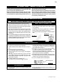
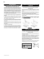
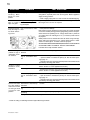
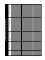
1
INSTALLER: THESE INSTRUCTIONS MUST BE CONVEYED TO AND REMAIN WITH THE HOMEOWNER.
CERTIFIED UNDER AMERICAN NATIONAL STANDARDS, ANSI Z21.11.2, VOLUME II FOR UNVENTED ROOM HEATERS.
UNVENTED MILLIVOLT SYSTEM
INSTALLATION AND OPERATION INSTRUCTIONS FOR
UNVENTED GAS FIREPLACE
CVF36N
MODEL CVF36P
NATURAL GAS MODEL
PROPANE GAS
CERTIFIED FOR UNITED STATES USING ANSI METHODS
WARNING: If the information in these instructions is not followed exactly, a fire or
explosion may result causing property damage, personal injury or death.
FOR YOUR SAFETY
Do not store or use gasoline or other flammable vapours and liquids in the vicinity of
this or any other appliance.
WHAT TO DO IF YOU SMELL GAS:
• If you cannot reach your gas supplier,
• Do not try to light any appliance.
call the fire department.
• Do not touch any electrical switch.
• Do not use any phone in your building.
• Immediately call your gas supplier from Installation and service must be performed
by a qualified installer, service agency or
a neighbour’s phone. Follow the gas
the gas supplier.
supplier’s instructions.
This is an unvented gas-fired heater that uses air (oxygen) from the room in which it is
installed. Provisions for adequate combustion and ventilation air must be provided.
Wolf Steel Ltd., 24 Napoleon Rd., Barrie, ON L4M 4Y8 Canada • (705)721-1212 • fax(705)722-6031
www.continentalplaces.com • [email protected]
$10.00
W415-0298 / K / 12.06.07
2
TABLE OF CONTENTS
PG 3-4 INTRODUCTION
9-10 OPTIONAL BLOWER
INSTALLATION
Warranty
General Instructions
General Information
Care of Glass Door, Catalytic Tiles &
Plated Parts
5-7
GD65 Fan Installation
GD36 Termostatic Sensor Control
11-12 OPERATION / MAINTENANCE
Combustion and Ventilation Air Provisions
Determining Confined or Unconfined Space
Gas Installation
Optional Wall Switch Installation
Dimensions
Minimum Framing Clearances
Nailing Tab Installation
Minimum Mantel and Enclosure Clearances
8-9
Operating Instructions
Maintenance
Oxygen Depletion Sensor Pilot Cleaning
Pilot Flame Appearance
Venturi Adjustment
INSTALLATION
FINISHING
13-14 REPLACEMENTS
Ordering Replacement Parts
Replacement Parts
Accessories
15-16 TROUBLE SHOOTING GUIDE
Grate and log installation
Charcoal Embers
Glowing Embers
Hood Installation
Logo Placement
Louvre Installation
17
SERVICE HISTORY
18
NOTES
PLEASE RETAIN THIS MANUAL FOR FUTURE REFERENCE
!
WARNING
• Under no circumstances should this heater be modified
• Provide adequate ventilation and combustion air. Provide adequate accessibility clearance for servicing and operating
the heater. Never obstruct the front opening of the heater.
• If the heater shuts off, do not re-light until you provide fresh air. If heater keeps shutting off, have it serviced. Keep
burner and control compartment clean.
• Do not burn wood or other materials in this heater.
• Adults and especially children should be alerted to the hazards of high surface temperatures and should stay away to
avoid burns or clothing ignition. Keep young children and animals away when the fireplace is hot.
• Due to high temperatures, the heater should be located out of traffic and away from furniture and draperies.
• Clothing or other flammable material should not be placed on or near the heater.
• Any safety screen or guard removed for servicing must be replaced prior to operating the heater.
• It is imperative that the control compartments, burners and circulating blower and its passageway in the fireplace
and venting system are kept clean. The fireplace and its venting system should be inspected before use and at least
annually by a qualified service person. More frequent cleaning may be required due to excessive lint from carpeting,
bedding material, etc. The fireplace area must be kept clear and free from combustible materials, gasoline and other
flammable vapours and liquids.
• Furniture or other objects must be kept a minimum of 4 feet away from the front of the fireplace.
• Do not use this fireplace if any part has been under water. Immediately call a qualified service technician to inspect the
fireplace and to replace any part of the control system and any gas control which has been under water.
• Do not allow fans to blow directly into the fireplace. Avoid any drafts that alter burner flame pattern.
• Do not use a blower insert, heat exchanger insert or other accessory not approved for use with this heater.
NOTE: CHANGES, OTHER THAN EDITORIAL, ARE DENOTED BY A VERTICAL LINE IN THE MARGIN.
W415-0298 / K / 12.06.07
3
CONTINENTAL® gas fireplaces are manufactured under the strict Standard of the world ized
recogn
ISO 9001:2000 Quality Assurance Certificate.
WOLF STEEL LTD. products are designed with superior components and materials
, assembled by ained
tr
craftsmen who take great pride in their work. The burner
d valve
an assembly are leak and t-fired
tes at aquality
test station. The complete fireplace is again
horoughly
t
inspected by a qualified technician before packaging
to
ensure that you, the customer, receiv
es the quality product at
th you expect from Wolf Steel Ltd.
CONTINENTAL® GAS FIREPLACE LIMITED WARRANTY
The following materials and workmanship in your new tinental®
Con
gas fireplace are warranted against defec
ts
for a period of five years. This covers:mbustion
co
chamber, heat exchanger, burner, phazer™ logs and embers,
ceramic glass (thermal breakage only), gold plated
parts against tarnishing, porcelainiz
ed enamelled components
and aluminum extrusion trims.
Electrical (110V and millivolt) component
s and wearable parts such as catalytic tiles, blowers, gas valves
thermal switch, switches, wiri
ng, remote controls, ignitor, gasketing, and pilot assembly are covered and
Wolf Steel Ltd. will provide replacementartsp free of charge duringthe first year of the lim
ited warranty.
Any labour related to warranty repair is not covered.
CONDITIONS AND LIMITATIONS
Wolf Steel Ltd. warrants its products against manufacturing defects to the original purchaser only -- i.e., the individual or legal entity (registered customer) whose name appears
on the warranty registration card filed with CONTINENTAL®® -- provided that the purchase was made through an authorized CONTINENTAL®® dealer and is subject to the following
conditions and limitations:
This factory warranty is nontransferable and may not be extended whatsoever by any of our representatives.
The gas fireplace must be installed by a licenced, authorized service technician or contractor. Installation must be done in accordance with the installation instructions included
with the product and all local and national building and fire codes.
This limited warranty does not cover damages caused by misuse, lack of maintenance, accident, alterations, abuse or neglect and parts installed from other manufacturers will nullify
this warranty.
This limited warranty further does not cover any scratches, dents, corrosion or discolouring caused by excessive heat, abrasive and chemical cleaners nor chipping on porcelain
enamel parts, mechanical breakage of PHAZER™ logs and embers, nor any venting components used in the installation of the fireplace.
In the first year only, this warranty extends to the repair or replacement of warranted parts which are defective in material or workmanship provided that the product has been operated
in accordance with the operation instructions and under normal conditions.
After the first year, with respect to this limited warranty, Wolf Steel Ltd. may, at its discretion, fully discharge all obligations with respect to this warranty by refunding to the original
warranted purchaser the wholesale price of any warranted but defective part(s).
Notwithstanding any provisions contained in this limited warranty, Wolf Steel Ltd.’S responsibility under this warranty is defined as above and it shall not in any event extend to any
incidental, consequential or indirect damages.
This warranty defines the obligations and liability of Wolf Steel Ltd. with respect to the CONTINENTAL®® gas fireplace and any other warranties expressed or implied with respect
to this product, its components or accessories are excluded.
Wolf Steel Ltd. neither assumes, nor authorizes any third party to assume, on its behalf, any other liabilities with respect to the sale of this product. Wolf Steel Ltd. will not be responsible
for: over-firing, downdrafts, spillage caused by environmental conditions such as rooftops, buildings, nearby trees, hills, mountains, inadequate vents or ventilation, excessive venting
configurations, insufficient makeup air, or negative air pressures which may or may not be caused by mechanical systems such as exhaust fans, furnaces, clothes dryers, etc.
Any damages to fireplace, combustion chamber, heat exchanger, brass trim or other component due to water, weather damage, long periods of dampness, condensation, damaging
chemicals or cleaners will not be the responsibility of Wolf Steel Ltd.
The bill of sale or copy will be required together with a serial number and a model number when making any warranty claims from your authorized dealer. The warranty registration
card must be returned within fourteen days to register the warranty.
Wolf Steel Ltd. reserves the right to have its representative inspect any product or part thereof prior to honouring any warranty claim.
ALL SPECIFICATIONS AND DESIGNS ARE SUBJECT TO CHANGE WITHOUT PRIOR NOTICE DUE TO ON-GOING PRODUCT IMPROVEMENTS. CONTINENTAL® IS A REGISTERED
TRADEMARK OF WOLF STEEL LTD. PATENTS U.S. 5.303.693.801 - CAN. 2.073.411, 2.082.915. © WOLF STEEL LTD.
W415-0298 / K / 12.06.07
4
GENERAL INSTRUCTIONS
THIS GAS FIREPLACE SHOULD BE INSTALLED AND
SERVICED BY A QUALIFIED INSTALLER to conform with
local codes. Installation practices vary from region to region
and it is important to know the specifics that apply to your
area, for example: in Massachusetts State:
•
•
•
The appliance off valve must be a “T” handle gas cock.
•
A carbon monoxide detector is required in all rooms containing
gas fired appliacnes.
•
WARNING: This product must be installed by a licensed
plumber or gas fitter when installed within the commonwealth
of Massachusetts.
The flexible connector must not be longer than 36“.
The appliance is not approved for installation in a bedroom or
bathroom unless the unit is a direct vent sealed combustion
product.
•
Un-vented room heater shall be installed in accordance with
527 CMR 30.00 and 248 CMR 3.00 through 7.00.
•
Sellers of un-vented propane or natural gas-fired space/room
heaters shall provide to each purchaser a copy of 527 CMR
30.00 upon the sale of the unit from
http://www.Continentalfireplaces.com/Webshare/
installation_manuals/mass_requirements.pdf
In absence of local codes, install the CVF36 to the current
National Fuel Gas Code, ANSI Z223.1 Installation Code
which can be obtained from:
American Nation Standards Institute Inc.
1430 Broadway
New York, NY 10018
or
National Fire Protection Association Inc.
Batterymarch Park
Quincy, MA 02269
The fireplace and its individual shutoff valve must be disconnected from the gas supply piping system during any pressure
testing of that system at test pressures in excess of 1/2 psig
(3.5 kPa). The fireplace must be isolated from the gas supply
piping system by closing its individual manual shutoff valve
during any pressure testing of the gas supply piping system
at test pressures equal to or less than 1/2 psig (3.5 kPa).
When the fireplace is installed directly on carpeting, vinyl tile
or other combustible material other than wood flooring, the
fireplace shall be installed on a metal or wood panel extending the full width and depth.
If the optional fan or blower is installed, the junction box
must be electrically connected and grounded in accordance
with local codes. In the absence of local codes, use the current ANSI/NFPA 70 NATIONAL ELECTRICAL CODE in the
United States.
Suitable for mobile home installation where the mobile
home has been permanently placed on its site. This heater must not be installed in a bedroom or bathroom.
This fireplace may be installed in an aftermarket permanently located, manufactured (mobile) home, where
not prohibited by local codes.
This fireplace is only for use with the type of gas indicated on the rating plate. This fireplace is not convertible
for use with other gases, unless a certified kit is used.
Minimum inlet gas supply pressure is 4.5“ water column for
natural gas and 11“ water column for propane. Maximum
inlet gas pressure is 7“ water column for natural gas and
13“ water column for propane. Manifold pressure under flow
conditions is 3.5“ water column for natural gas and 10“ water
column for propane.
CARE OF PLATED PARTS
No external electricity (110 volts or 24 volts) is required
for the gas system operation.
Expansion / contraction noises during heating up and cooling
down cycles are normal and are to be expected.
Do not use abrasive cleaners to clean plated parts. Buff lightly
with a clean dry cloth.
This heater is equipped with a pilot light safety
system referred to as an OXYGEN DEPLETION
SENSOR and is designed to turn off the heater
if not enough fresh air is available.
Use only accessories designed for and
listed with your specific fireplace.
CARBON MONOXIDE POISONING MAY
LEAD TO DEATH
Early signs of carbon monoxide poisoning resemble the flu, with headache, dizziness and/or nausea. If you have these signs, the heater may not
be working properly. Get fresh air at once! Have
heater serviced.
GENERAL INFORMATION
FOR YOUR SATISFACTION, THIS FIREPLACE HAS BEEN
TEST-FIRED TO ASSURE ITS OPERATION AND QUALITY! Maximum input is 30,000 BTU/hr for natural gas and
propane. When the fireplace is installed at elevations above
2,000ft, and in the absence of specific recommendations
from the local authority having jurisdiction, the certified high
altitude input rating shall be reduced at the rate of 4% for
each additional 1,000ft.
W415-0298 / K / 12.06.07
Some people---pregnant women, persons with heart
or lung disease, anaemia, those under the influence
of alcohol, those at high altitudes--- are more affected by carbon monoxide than others.
Ceiling fans or oscillating type floor fans can cause flame
impingement if directing air at the fireplace. Impinging
flames will cause soot or carbon that may enter into living
area. Try reversing ceiling fan or re-directing floor fans to
prevent sooting.
5
INSTALLATION
COMBUSTION & VENTILATION
AIR PROVISIONS
DETERMINING CONFINED OR UNCONFINED SPACE
This heater shall not be installed in a confined space
or unusually tight construction unless provisions are
provided for adequate combustion and ventilation air.
In order to avoid the possibility of exposed insulation
or vapour barrier coming in contact with the fireplace
body, it is recommended that the walls of the fireplace
enclosure be ‘finished’, (i.e. drywall/sheetrock) as would
any other outside wall of the home. This will ensure
that clearance to combustibles is maintained within
the cavity.
The National Fuel Gas Code, ANSI Z223.1 defines a confined
space as a space whose volume is less than 50 cubic feet
per 1,000 Btu per hour (4.8 m3 per kW) of the aggregate
input rating of all appliances installed in that space and an
unconfined space as a space whose volume is not less than
50 cubic feet per 1,000 Btu per hour (4.8 m3 per kW) of the
aggregate input rating of all appliances installed in that space.
Rooms communicating directly with the space in which the
appliances are installed, through openings not furnished with
doors are considered a part of the unconfined space.
To determine the volume of the room where the heater is to
be installed, multiply the width x the length x the ceiling height
of that room measured in feet. If any adjoining rooms are connected by grills or openings such as kitchen pass-throughs,
etc., the volume of those rooms may be added to the total.
Multiply the room volume by 1000 and divide this amount
by 50 to determine the maximum Btu/hr that the space can
support with adequate combustion and ventilation air.
Add the Btu/hr of all fuel burning appliances located within
the space such as gas furnace, gas water heater, etc. Do not
include direct vent gas appliances which draw their input and
output air from and to the outdoors.
WARNING: If the area in which the heater may be operated
is smaller than that defined as an unconfined space or if the
building is of unusually tight construction, provide adequate
combustion and ventilation air by one of the methods described in the National Fuel Gas Code ANSI Z223.1, Section
5.3 or the applicable local code.
The CVF36 is rated at 30,000BTUs per hour and
therefore requires a minimum unconfined space
of 1,500 cubic feet.
ROOM 2
ROOM 1
FIGURE 1
HEIGHT
TH
ID
W
LENGTH
If for example,
the length of the rooms is 10 feet,
the width of Room 1 is 10 feet,
the width of Room 2 is 15 feet
the height of the rooms is 8 feet.
The volume of Room 1: 10 x 10 x 8 = 800 cubic feet.
The volume of Room 2: 10 x 15 x 8 = 1200 cubic feet.
Room Volume = Length x Width x Height
Max BTU/hr = Room Volume x 1000 ÷ 50
EXAMPLE 1
In this example, because there is no door to the adjoining
room, the volume of the adjoining room may be added to the
volume of the room with the heater to get a total unconfined
space.
The total unconfined space: 800 + 1200 = 2000 cubic feet.
Maximum BTU/h:
2000 x 1000
50
= 40,000 BTU/h
If there are no more fuel burning appliances within this space
then the 30,000 BTU/h input of the fireplace is suitable to
be installed. This also assumes that the construction of this
space is not unusually tight.
EXAMPLE 2
If in this example a solid door separates Room 1 from Room
2, the volume of Room 2 could not be used. In this case the
maximum BTU/h would be:
800 x 1000
= 16,000 BTU/h
50
This would be considered a confined space since it can not
support the 30,000BTU/h input of the heater and it would be
necessary to provide adequate combustion and ventilation
air to Room 1.
Maximum BTU/h:
W415-0298 / K / 12.06.07
6
Unusually tight construction is defined as construction where:
a) Walls and ceilings exposed to the outside atmosphere
have a continuous water vapour retarder with a rating of
1 perm (6 x 10-11 kg per pa-sec-m2) or less with openings
gasketed or sealed, and
b) Weather stripping has been added on openable windows and doors, and
c) Caulking or sealants are applied to areas such as
joints around window and door frames, between sole plates
and floors, between wall-ceiling joints, between wall panels,
at penetrations for plumbing, electrical, and gas lines, and
at other openings.
An unvented room heater is recommended for use as a
secondary heat source rather than as a primary source.
Gas combustion produces water vapour which could occur
at the rate of approximately one ounce of water for every
1,000 BTU/hr of gas input. During the cold weather season,
indoor humidity levels tend to be low. Consequently, this
water vapour can enhance the living space. However if a
problem should occur:
a) ensure sufficient combustion and circulation air
b) use a dehumidifier
c) do not use the unvented room heater as a primary
heat source
Without sufficient fresh air for proper operation, poor fuel
combustion can result. Carbon Monoxide is a result of poor
combustion.
If additional fresh air is required, use one of the methods described in the National Fuel Gas Code, ANSI Z223.1,
Section 5.3 or the applicable local code.
GAS INSTALLATION
Proceed once the vent installation is complete.
NOTE: All gas connections must be contained within
the fireplace when complete.
1. Move the fireplace into position and secure to the floor
through the 1/4" holes located at either side of the base.
2. The fireplace is designed to accept 3/8" gas supply line.
The fireplace is equipped with a 3/8" manual shut-off valve.
3. Connect the gas supply in accordance to local codes.
In the absence thereof, install according to the National
Installation Code.
4. When flexing any gas line, support the gas valve so
that the lines are not bent or kinked.
5. Check for gas leaks by brushing on a soap and water
solution.
DO NOT USE OPEN FLAME.
OPTIONAL WALL SWITCH
INSTALLATION
For ease of accessibility, an optional remote wall switch may
be installed in a convenient location. A 20’ length of millivolt
wire is connected to the gas valve for the wall switch. However if a greater length is required route 2-strand (solid core)
millivolt wire through the electrical hole located at the bottom
left side of the unit. The recommended maximum lead length
depends on wire size:
WIRE SIZE
14 gauge
16 gauge
18 gauge
MAX. LENGTH
100 feet
60 feet
40 feet
FIGURE 2
FIGURE 3
W415-0298 / K / 12.06.07
7
MINIMUM FRAMING CLEARANCES
FIGURE 4
Combustible materials may be installed flush with the front of
the fireplace but must not cover any of the black face-areas of
the fireplace. Non-combustible material (brick, stone or ceramic
tile) may protrude in these areas.
It is not necessary to install a hearth extension with this fireplace
system.
When roughing in the fireplace, raise the fireplace to accommodate for the thickness of the finished floor materials, i.e. tile,
carpeting, hard wood, which if not planned for will interfere with
the opening of the lower access door and the installation of many
decorative flashing accessories.
Objects placed in front of the fireplace should be kept a minimum
of 4 feet away from the front face.
NAILING TAB INSTALLATION
To install the fireplace face
flush with the finished wall,
position the framework to accommodate the thickness of
the finished wall. Bend out the
four nailing tabs, attached on
either side of the fireplace and
secure to the 2x4 framing. The
tabs will facilitate the installation
3
of either a /4” or a 1” finished
wall thickness. The nailing
tabs must not be removed.
FIGURE 5
FIGURE 8
NAILING
TAB
MINIMUM MANTEL AND ENCLOSURE
CLEARANCES
FIGURE 6
Combustible mantel clearance can vary according to the mantel
depth. Use the graph to help evaluate the clearance needed.
FIGURE 9a-c
FIGURE 7
Combustion protrusions such as
mantels and shelves may occur
at or after a minimum distance of 2”
away from the side of the fireplace. Thereafter, the depth
of any protrusions must be of equal to or less than the
distance from the side of the fireplace up to a depth of 6”,
after which no greater clearance than 6” is required. This
can be considered a side wall with no length boundary.
It is best to frame your fireplace after it is positioned. Use 2x4’s
and frame to local building codes. FIGURE 5-7.
Minimum clearance to combustible construction from fireplace:
sides, back, bottom and top of the unit
0”
recessed depth
13 1/2”
Note: In order to avoid the possibility of exposed insulation
or vapour barrier coming in contact with the fireplace body,
it is recommended that the walls of the fireplace enclosure
be “finished” (ie: drywall/sheetrock), as you would finish any
other outside wall of a home. This will ensure that clearance to
combustibles is maintained within the cavity.
The fireplace requires a minimum enclosure height of 39”. For
temperature requirements, the enclosure space around and
above the fireplace must be left unobstructed.
W415-0298 / K / 12.06.07
8
FINISHING
GRATE AND LOG INSTALLATION
HOOD
1. Remove curtain mesh and rod assembly
FIGURE 11
2. Remove log carton
3. Remove grate from the lower control area (stored there when
shipped)
HOOD
4. Unscrew the 3 screws in the firebox, set grate in place
and secure using the 3 screws that were just removed.
See Figure 11.
5. Install the one piece logset by aligning the two holes on the
bottom of the logs, with the two locating pins in the
firebox.
CURTAIN
MESH
NOTE: PHAZERTM logs and glowing embers exclusive to
Continental® Fireplaces, provide a unique and realistic
glowing effect that is different in every installation. Take the
time to carefully position the glowing embers for a maximum
glowing effect.
Log colours may vary. During the initial use of the fireplace,
the colours will become more uniform as colour pigments
burn in during the heat activated curing process.
The curtain mesh must be kept fully closed during operation
to help prevent accidental burns from occurring.
6. Reinstall rod assembly and mesh curtain
FIGURE 10
FIGURE 12
CHARCOAL EMBERS
Randomly place the charcoal embers along the front and
sides of the log support tray in a realistic manner. Fine dust
found in the bottom of the bag should not be used.
The heater must not be used when the hood is removed. Hook the hood over the lip of the curtain support
plate.
LOGO PLACEMENT
GLOWING EMBERS
Tear the embers into pieces and place along the front row
of ports covering all of the burner area in front of the small
logs (#2 & #3). Care should be taken to shred the embers
into thin, small irregular pieces as only the exposed edges of
the fibre hairs will glow. The ember material will only glow
when exposed to direct flame; however, care should be
taken to not block the burner ports.
Blocked burner ports can cause an incorrect flame pattern,
carbon deposits and delayed ignition. PHAZERTM logs glow
when exposed to direct flame. Use only certified “glowing
embers” and PHAZERTM logs available from your Continental® dealer.
W415-0298 / K / 12.06.07
Remove the backing of
the logo supplied and
place on the screen
cover, as indicated.
FIGURE 13
9
L36 LOUVRE INSTALLATION
A
CLIPS
FIGURE14
A
FLANGE
HOOD
Attach the hood by pressing the
top flange into the clips along
the top of the louvre opening.
Secure using a screw through
the centre slot.
CENTRE
SLOT
B
SLOT
UPPER LOUVRES
Insert the louvre tabs into the
slots located at the top left and
right corners of the unit.
TAB
B
C
HINGE
CLIP
C
SLOT
LOWER LOUVRES
Insert the hinge clips into the
slots located at the bottom left
and right corners of the unit.
To remove the louvres, pull the
back tabs of the clips forward,
while pushing the louvre assembly back. Lift the clip.
OPTIONAL BLOWER INSTALLATION
INSTALLATION TO BE DONE BY A QUALIFIED INSTALLER
and must be electrically connected and grounded in accordance with local codes. In the absence of local codes, use the
current ANSI/NFPA 70 NATIONAL ELECTRICAL CODE.
the bracket before installing the blower. Attach the black and
white wires to the disc, then secure the bracket to the stud
at the bottom left on the unit using the lock washer and wing
nut. Ensure that the thermodisc touches the firebox wall.
FIGURE 15
If the fireplace was not
previously equipped
with a blower: route a
grounded 2-wire, 60hz
power cable to the junction box. At this point, it
must be strain relieved
and insulated.
The three slots on the
blower mounting bracket
allow ease of adjustment
when attaching the blower. For a quiet running
blower, do not allow the
assembly to sit on the
firebox base.
Slide the vibration reducing pad (A) into the clip (C) and up
against the threaded stud (B) at the other end. The blower
must be able to be positioned entirely onto the pad.
Tilt the blower onto its side. Slide it past the controls and
into the clip (C). Secure to the threaded stud using the lock
washer and wing nut provided. Ensure that the blower does
not touch the fireplace base or the firebox.
B
FIGURE 16
If optional blower kit is to be installed, remove thermodisc
from the bracket supplied in the kit and disgard the bracket.
Install thermodisc in the bracket supplied with the fireplace. It
is recommended to attach the wires to the disc and install
C
A
FIGURE 17
FIGURE 18
W415-0298 / K / 12.06.07
10
FIGURE 19
FIGURE 22
Slide the fan assembly
past the controls and into
the clip. Secure using
the lock washer and nut
provided. Plug the harness cord
into the receptacle.
Attach the connectors from
the black and red wires to the
blower.
Attach and secure the variable
speed switch using the nut
provided. Plug the harness
cord into the receptacle.
FIGURE 20
The wire harness provided in this kit is a universal
harness. When installed, ensure that any excess
wire is contained, preventing it from making contact with moving or hot objects.
Because the blower is thermally activated, when
turned on, it will automatically start approximately
10 minutes after lighting the fireplace and will
run for approximately 30-45 after the fireplace
has been turned off. Use of the fan increases the
output of heat.
Drywall dust will penetrate into the blower bearings causing irreparable damage. Care must be
taken to prevent drywall dust from coming into
contact with the blower or its compartment. Any
damage resulting from this condition is not covered by the warranty policy.
GD65 FAN INSTALLATION
ELECTRICAL INSTALLATION
TO BE DONE BY A QUALIFIED INSTALLER and must
be connected and grounded in
accordance with local codes.
In the absence of local codes,
use the current ANSI/NFPA 70
NATIONAL ELECTRICAL CODE.
FIGURE 21
If the fireplace was not previously equipped with a blower,
route a grounded 2-wire, 60hz power cable to the junction
box. At this point, it must be strain relieved and insulated.
The wire harness provided in this kit is a universal harness.
When installed, ensure that any excess wire is contained, preventing it from making contact with moving or hot objects.
Position the vibration reducing pad into the clip and onto the
threaded stud at the other end, piercing a hole into the pad.
The fan assembly must be able to be positioned entirely
onto the pad.
W415-0298 / K / 12.06.07
GD36 THERMOSTATIC SENSOR
CONTROL
This optional kit is meant to be used only in conjunction with
the GD65 Fan Kit, which may be ordered from your Wolf
Steel /Continental® dealer.
With the thermostatic sensor option, the fan, when turned
on, becomes thermally activated, and will automatically run
approximately 10 minutes after the fireplace has been lit
and for approximately 30-45 minutes after the fireplace has
been turned off.
Use of the fan increases the output of heat.
If optional thermostatic sensor kit is to be installed, remove
thermodisc from the bracket supplied in the kit and disgard
the bracket. Install thermodisc in the bracket supplied with the
fireplace. It is recommended to attach the wires to the disc
and install the bracket before installing the blower. Attach the
black and white wires to the disc, then secure the bracket to
the stud at the bottom left on the unit using the lock washer
and wing nut. Ensure that the thermodisc touches the firebox
wall.
FIGURE 23
Unplug the
power cord
from the
receptacle.
Connect
all wires as
shown.
Plug the
power cord back into the receptacle.
When installed, ensure that any excess wire is contained, preventing it from making contact with moving or hot objects.
FIGURE 24
11
OPERATION / MAINTENANCE
If heater shuts off, do not relight until you provide fresh
air. If heater keeps shutting off, have it serviced. Keep
burner and control compartment clean.
When lit for the first time, the fireplace will emit a slight
odour for a few hours. This is a normal temporary condition caused by the curing of the logs and the “burn-in” of
internal paints and lubricants used in the manufacturing
process and will not occur again.
After extended periods of non-operation such as following a vacation or a warm weather season, the fireplace
may emit a slight odour for a few hours. This is caused by
dust particles burning off. In both cases, open a window
to sufficiently ventilate the room.
FOR YOUR SAFETY READ BEFORE LIGHTING:
WARNING: IF YOU DO NOT FOLLOW THESE INSTRUCTIONS EXACTLY, A FIRE OR EXPLOSION
MAY RESULT CAUSING PROPERTY DAMAGE, PERSONAL INJURY OR LOSS OF LIFE.
A. This fireplace is equipped with a pilot which must be
WHAT TO DO IF YOU SMELL GAS:
lit by hand while following these instructions exactly.
B. Before operating smell all around the fireplace area for
• Do not try to light any appliance.
gas and next to the floor because some gas is heavier
• Do not touch any electric switch; do not use any phone
than air and will settle on the floor.
in your building.
C. Use only your hand to push in and turn the gas control
• Immediately call your gas supplier from a neighbour’s
knob. Never use tools. If the knob will not push in and
phone. Follow the gas supplier’s instructions.
turn by hand, do not try to repair it. Call a qualified service
• If you cannot reach your gas supplier, call the fire departtechnician. Force or attempted repair may result in a fire
ment.
or explosion.
FIGURE 26
D. Do not use this fireplace if any part has been under water.
FIGURE 25
Immediately call a qualified service technician to inspect the
fireplace and replace any part of the control system and any
gas control which has been under water.
OXYGEN DEPLETION SENSOR
GAS KNOB
LIGHTING INSTRUCTIONS
When lighting and re-lighting, the gas knob cannot be turned
from pilot to off unless the knob is depressed.
1. STOP! Read the above safety information on this label.
2. Set the thermostat to lowest setting.
3. Turn off all electric power to the fireplace.
4. Open the control door. Turn the gas knob clockwise
to off.
5. Wait five (5) minutes to clear out any gas. If you smell
gas including near the floor, STOP! Follow “B” in the
above safety information on this label. If you don’t smell
gas go to the next step.
6. Find pilot located in front of the back log.
7. Turn gas knob counter-clockwise
to pilot.
8. Depress and hold gas knob while lighting the pilot with
the push button igniter. Keep knob fully depressed for
one minute, then release. If pilot does not continue to
burn repeat steps 3 through 7.
9. With pilot lit, turn gas knob counter-clockwise
to
on. When the pilot has been turned off, ignition of the
main burner may be delayed from 1-2 minutes.
When the pilot has been left burning, ignition of the main
burner should occur almost immediatley.
10. If equipped with remote on-off switch, main burner may
not come on when you turn the valve to on. Remote switch
must be in the on position to ignite burner.
11. Turn on all electric power to the fireplace.
GAS KNOB AT OFF
FIGURE 27
TO TURN OFF GAS
1. Turn off all electric power to the fireplace if service is to
be performed.
2. Push in gas control knob slightly and turn clockwise
to off. Do not force.
W415-0298 / K / 12.06.07
12
MAINTENANCE
TURN OFF THE GAS AND ELECTRICAL POWER
BEFORE SERVICING THE FIREPLACE.
CAUTION: Label all wires prior to disconnection when servicing controls. Wiring errors can cause improper and dangerous
operation. Verify proper operation after servicing. This heater
should be inspected and serviced before use and at least annually by a qualified service person. The fireplace area must
be kept clear and free of combustible materials, gasoline or
other flammable vapours and liquids. The flow of combustion
and ventilation air must not be obstructed.
1. In order to properly clean the burner and oxygen depletion sensor system, remove the logs to expose both assemblies.
2. Keep the control compartment, logs, burner, air shutter
opening and the area surrounding the logs clean by vacuuming or brushing, at least once a year.
3. Check to see that all burner ports are burning. Clean out
any of the ports which may not be burning or are not burning properly.
4. Check to see that the pilot flame is large enough to engulf
the thermocouple and thermopile and promptly ignites the
main burner.
5. Replace the cleaned logs.
6. Check to see that the main burner ignites completely on
all openings when the gas knob for the burner is turned on. A
5 to 10 second total light-up period is satisfactory. If ignition
takes longer, consult your Continental® dealer / distributor.
OXYGEN DEPLETION SENSOR PILOT
CLEANING
This procedure must be performed by a qualified
service person!
Inspect the pilot for any visible contamination or debris
(usually lint, pet hair, spider webs, carpet fibre, etc.) and
remove.
Disconnect the pilot from the pilot tubing line. Using a 7/16”
wrench, remove the injector from the pilot housing. Blow out
the housing in the same direction as the gas flow.
Re-install the injector and the pilot tube, turn on the gas and
check for leaks.
If this does not improve the performance, replace the pilot
with an exact replacement. The device is tamper resistant
with no field serviceable parts.
CORRECT PILOT
FLAME
INCORRECT PILOT
FLAME
FIGURES 28
VENTURI ADJUSTMENT
Air shutter adjustment must only be done by a qualified gas installer!
Closing the air shutter will cause a more yellow flame, but
can lead to carboning.
WARNING: Carbon can be distributed in surrounding
living area if the air shutter is improperly adjusted.
Opening the air shutter will cause a more blue flame, but can
cause flame lifting from the burner ports. The flame may not
appear yellow immediately; allow 15 to 30 minutes for the
final flame colour to be established.
Opening the air shutter will also reduce exhaust odours
smelled within the room. See Trouble Shooting Guide.
AIR SHUTTER OPENINGS
NG
3/16”
LP
1/2”
FIGURES 29
W415-0298 / K / 12.06.07
13
REPLACEMENTS
Contact your dealer for questions concerning prices and
availability of replacement parts. Normally all parts can be
ordered through your Continental® dealer or distributor.
When ordering replacement parts always give the following
information:
FOR WARRANTY REPLACEMENT PARTS, A PHOTOCOPY OF
1.
2.
3.
4.
5.
MODEL & SERIAL NUMBER OF FIREPLACE
INSTALLATION DATE OF FIREPLACE
PART NUMBER
DESCRIPTION OF PART
FINISH
THE ORIGINAL INVOICE WILL BE REQUIRED TO HONOUR
THE CLAIM.
* IDENTIFIES ITEMS WHICH ARE NOT ILLUSTRATED. FOR FURTHER INFORMATION, CONTACT YOUR CONTINENTAL®
REPLACEMENT PARTS
ACCESSORIES
#
PART NO. DESCRIPTION
#
PART NO. DESCRIPTION
1
2
2
3*
4
4
5*
6*
7
8*
9*
10
10
11
11
12
13
14
15*
16
17
W357-0001
W662-0001
W662-0002
W680-0004
W725-0030
W725-0031
W385-0245
W750-0112
GL-664
W361-0016
W550-0001
W010-0764
W010-0987
W455-0026
W455-0059
W335-0050
W565-0058
W555-0033
W080-0507
W500-0184
W630-0010
18*
19*
20*
21*
22
23*
24*
25*
25*
26
26
27
27
27
27
27
27
28
28
28
28
28
29
29
29
29
30
30
30
30
31
31
31
31
W690-0001
W660-0011
W660-0013
W500-0033
GZ550-KT
GD65
GD36
GD825-N
GD825-P
CDV4L
CDV4LSS
HOIK-1
HOIG-1
HOIKG-1
HOIBC-1
HOIBG-1
HOISS-1
DOIG-1
DOIKG-1
DOIBC-1
DOIBG-1
DOISS-1
GOIG-1
GOIKG-1
GOIBC-1
GOIBG-1
SOIG-1
SOIKG-1
SOIBC-1
SOIBG-1
EOIG-1
EOIKG-1
EOIBC-1
EOIBG-1
PIEZO IGNITER
OXYGEN DEPLETION SENSOR SYSTEM - NG
OXYGEN DEPLETION SENSOR SYSTEM - LP
THERMOPILE
NATURAL GAS VALVE
PROPANE GAS VALVE
CONTINENTAL® LOGO
20FT OF WIRE
ONE PIECE LOG SET (W135-0335)
GLOWING EMBERS
CHARCOAL EMBERS
PAN BURNER(NG)
PAN BURNER(LP)
#38 NATURAL GAS BURNER ORIFICE
#53 PROPANE GAS BURNER ORIFICE
HOOD
CURTAIN MESH
CURTAIN ROD
CURTAIN ROD BRACKET
CURTAIN SUPPORT PLATE
BLACK TASSELS
MILLIVOLT THERMOSTAT
REMOTE CONTROL - ADVANTAGE PLUS
MODULATING REMOTE
VARIABLE SPEED SWITCH WALL MOUNTING PLATE
BLOWER KIT
FAN KIT
THERMOSTATIC SENSOR CONTROL KITUSE W/ GD65 ONLY
MODULATING REGULATOR NG
MODULATING REGULATOR LP
LOUVRE OVERLAY
LOUVRE OVERLAY - STAINLESS STEEL
HERITAGE ORNAMENTAL INSETS - BLACK
HERITAGE ORNAMENTAL INSETS - GOLD PLATED
HERITAGE ORNAMENTAL INSETS - BLACK GOLD PLATED
HERITAGE ORNAMENTAL INSETS - BRUSHED COPPER PLATED
HERITAGE ORNAMENTAL INSETS - BRUSHED GOLD PLATED
HERITAGE ORNAMENTAL INSETS - BRUSHED STAINLESS STEEL
DIAMOND ORNAMENTAL INSETS - GOLD PLATED
DIAMOND ORNAMENTAL INSETS- BLACK GOLD PLATED
DIAMOND ORNAMENTAL INSETS- BRUSHED COPPER PLATED
DIAMOND ORNAMENTAL INSETS- BRUSHED GOLD PLATED
DIAMOND ORNAMENTAL INSETS - BRUSHED STAINLESS STEEL
GOTHIC ORNAMENTAL INSETS - GOLD PLATED
GOTHIC ORNAMENTAL INSETS - BLACK GOLD PLATED
GOTHIC ORNAMENTAL INSETS - BRUSHED COPPER PLATED
GOTHIC ORNAMENTAL INSETS - BRUSHED GOLD PLATED
SEASHELL ORNAMENTAL INSETS - GOLD PLATED
SEASHELL ORNAMENTAL INSETS - BLACK GOLD PLATED
SEASHELL ORNAMENTAL INSETS - BRUSHED COPPER PLATED
SEASHELL ORNAMENTAL INSETS - BRUSHED GOLD PLATED
ECLIPSE ORNAMENTAL INSETS - GOLD PLATED
ECLIPSE ORNAMENTAL INSETS - BLACK GOLD PLATED
ECLIPSE ORNAMENTAL INSETS - BRUSHED COPPER PLATED
ECLIPSE ORNAMENTAL INSETS - BRUSHED GOLD PLATED
W415-0298 / K / 12.06.07
14
W415-0298 / K / 12.06.07
15
TROUBLE SHOOTING GUIDE
BEFORE ATTEMPTING TO TROUBLESHOOT, PURGE YOUR UNIT AND INITIALLY LIGHT THE PILOT AND THE MAIN BURNER WITH THE GLASS DOOR REMOVED.
SYMPTOM
PROBLEM
TEST SOLUTION
Main burner goes Pilot flame is not large enough - service or replace Oxygen Depletion Sensor System
out; pilot stays on. or not engulfing the thermo- - correct piping and/or regulator to provide correct pressure
pile
Thermopile shorting
- clean thermopile connection to the valve. Reconnect.
- replace Oxygen Depletion Sensor System / valve.
Remote wall switch wire is too - shorten wire to correct length or wire gauge.
long; too much resistance in
the system.
Faulty thermostat or switch.
Main burner goes Insufficient air supply
out; pilot goes out.
Out of propane gas.
- replace.
- open window or door. (Use one of the methods described in ANSI
Z223.1 Section 5.3 or the applicable local code.)
- fill the tank.
Pilot flame is not large enough. - service or replace Oxygen Depletion Sensor System
(Supply pressure too low.)
- correct piping and / or regulator to provide correct pressure.
Pilot goes out when
the gas knob is released.
The gas valve has
an interlock device
which will not allow the pilot burner to be lit until
the thermocouple
has cooled. Allow
approximately 60
seconds for the
thermocouple to
cool.
S y s t e m i s n o t c o r r e c t l y - purge the gas line. If a glass door has been installed, ensure that the
purged.
door is open or removed prior to purging.
Pilot burning; no
gas to main burner;
gas knob is on ‘HI’;
wall switch / thermostat is on.
Themostat or switch is de- - connect a jumper wire across the wall switch terminals; if main burner
lights, replace switch / thermostat.
fective.
Out of propane gas.
Pilot flame is not large enough. - service or replace Oxygen Depletion Sensor System
(Supply pressure too low.)
Thermocouple shorting / faulty.
Faulty valve.
- replace.
Main burner orifice is
- remove stoppage in orifice.
Faulty valve.
- replace.
No spark at pilot burner
THERMOPILE
PILOT
BURNER
ELECTRODE
loosen and tighten thermocouple.
clean thermocouple and valve connection.
replace Oxygen Depletion Sensor System
test and replace valve.
Wall switch wiring is defec- - disconnect wires from valve. Connect a jumper wire across terminals
tive.
1 & 3; if the main burner lights, check the wires for defects and / or
replace wires.
Pilot will not light. Out of propane gas
THERMOCOUPLE
- fill the tank.
No gas at the pilot burner
- fill the tank.
-
check if pilot can be lit by a match
check that the wire is connected to the push button ignitor.
check if the push button ignitor needs tightening.
replace the wire if the wire insulation is broken or frayed.
replace the electrode if the ceramic insulator is cracked or broken.
replace the push button ignitor.
-
check that the manual valve is turned on.
check the pilot orifice for blockage.
replace the valve / Oxygen Depletion Sensor System.
call the gas distributor.
W415-0298 / K / 12.06.07
16
SYMPTOM
PROBLEM
Pilot goes out while Gas piping is undersized.
standing; Main
burner is in ‘OFF’
position.
TEST SOLUTION
- turn on all gas appliances and see if pilot flame flutters, diminishes or
extinguishes, especially when main burner ignites. Monitor appliance
supply working pressure.
- check if supply piping size is to code. Correct all undersized piping.
Main burner will not Inlet pressure too high.
Adjust inlet pressure to ensure maximum 7.0” W.C. at gas valve for
light, or is slow to Pilot flame blowing off, miss- Natural gas and 13.0” W.C. for Propane.
light; noisy pilot.
ing thermopile.
Flames are consist- Unit is over-fired or under- - check pressure readings:
ently too large or fired.
Inlet pressure can be checked by turning screw (A) counter-clockwise
too small. Carbon2 or 3 turns and then placing pressure gauge tubing over the test point.
ing occurs.
Check with burner operating on “HI”. Gauge should read 7” (minimum
4.5”) water column for natural gas or 13” (11” minimum) water column
for propane.
Outlet pressure can be checked the same as above using screw (B).
Check with burner operating on “HI”. Gauge should read 3.5” water
column for natural gas or 10” water column for propane.
AFTER TAKING PRESSURE READINGS, BE SURE TO TURN SCREWS
CLOCKWISE FIRMLY TO RESEAL. DO NOT OVERTORQUE.
Leak test with a soap and water solution.
Carbon is being de- Air shutter has become - ensure air shutter opening is free of lint or other obstructions.
posited on logs or blocked
combustion chamFlame is impinging on the
- check that the logs are correctly positioned.
ber surfaces.
logs or combustion cham- *open air shutter to increase the primary air. See air shutter openber.
ings, page 13.
- check the input rate: check the manifold pressure and orifice size as
specified by the rating plate values.
Not
enough
combustion
air.
- increase fresh air supply. (Use one of the methods described in ANSI
Exhaust fumes
Z223.1 Section 5.3 or the applicable local code.)
smelled in room,
headaches.
Remote wall switch
is in “OFF” position;
main burner comes
on when gas knob
is turned to “ON”
position.
Not enough ventilation air.
- increase fresh air supply. (Use one of the methods described in ANSI
Z223.1 Section 5.3 or the applicable local code.)
Flame is impinging on the
logs or combustion chamber.
- check that the logs are correctly positioned.
- open air shutter to increase the primary air. See air shutter openings, page 13.
- check the input rate: check the manifold pressure and orifice size as
specified by the rating plate values.
Wall switch is mounted up- - reverse.
side down
Remote wall switch is ground- - replace.
ing.
Remote wall switch wire is - check for ground (short); repair ground or replace wire.
grounding.
- replace.
Faulty valve.
* Check for ceiling or oscillating fans that maybe influencing the flame.
W415-0298 / K / 12.06.07
Date
Dealer Name
Service Technician
Name
Service Performed
This fireplace must be serviced annually depending on usage.
Wolf Steel Fireplace Service History
Special Concerns
17
W415-0298 / K / 12.06.07
18
NOTES
W415-0298 / K / 12.06.07