1
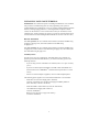
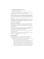
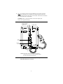
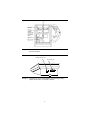
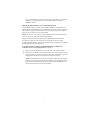
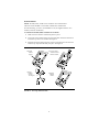
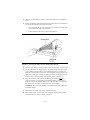
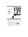
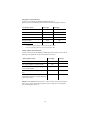
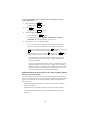
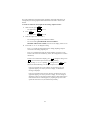
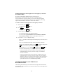
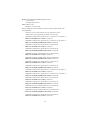
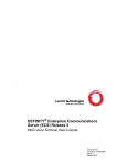
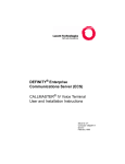
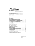
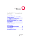
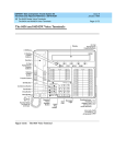
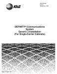
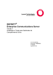
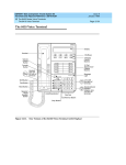
The 8400-Series Voice Terminals
Installation and User’s Manual
(includes instructions for the 8403, 8405,
8410, 8411, and 8434DX voice terminals)
DO NOT DISCARD THE BLANK DESIGNATION CARD
The voice terminal is shipped with a blank button designation card in place under the
transparent cover. Do not discard this button designation card. Instead, place the preprinted
designation card over the blank button designation card which comes with the voice terminal.
This blank designation card can then be used as a substitute if, in the future, there are changes in
features, telephone numbers, or extension assignments on the voice terminal.
ENVIRONMENTAL INFORMATION
In accordance with international environmental standards, parts of this Lucent Technologies
voice terminal have been manufactured with recyclable plastic resins. These telephone parts
have been marked >ABS< so they can be easily identified at recycling or waste recovery
facilities when appropriate. The paper used in this documentation is also recyclable.
REFERENCES TO AT&T
Any references within this text to American Telephone and Telegraph Corporation or AT&T
should be interpreted as references to Lucent Technologies Incorporated. The exception is crossreferences to books published prior to December 31, 1996, which retain their original AT&T
titles.
THE “CE” MARK
If the “CE” mark is affixed to this equipment, it means that it conforms to the European Union
Electromagnetic Compatibility Directive (89/336/EEC) and the Low Voltage Directive (73/23/
EEC).
WARNING
This is a Class A product as defined by EN55022:1998. In a domestic environment this product
may cause radio interference, in which case the user may be required to take adequate measures.
RESPONSIBILITY FOR THE SYSTEM'S SECURITY
The system manager for each PBX system is responsible for the system’s security. Lucent
Technologies does not warrant that this product is immune from or will prevent unauthorized
use of common-carrier telecommunication services or facilities accessed through or connected
to it. Lucent Technologies will not be responsible for any charges that result from such
unauthorized use. Product administration to prevent unauthorized use is the responsibility of the
system manager, and he or she should read all documents provided with this product to fully
understand the features available that may reduce the risk of incurring unauthorized charges.
TRADEMARKS
DEFINITY, QUORUM, and PassageWay are registered trademarks of Lucent Technologies.
IBM is a registered trademark of International Business Machines Corporation.
WARRANTY
All terms and conditions specified in the owner’s agreement with Lucent Technologies apply.
HEARING AID COMPATIBILITY
These voice terminals are Hearing Aid Compatible (“HAC”). In addition, some units have an
“HAC” label on them.
IMPORTANT USER SAFETY
INSTRUCTIONS
The most careful attention has been devoted to quality standards in the
manufacture of your new voice terminal. Safety is a major factor in the design of
every set. But, safety is YOUR responsibility too.
Please read carefully the helpful tips listed below and on the next page. These
suggestions will enable you to take full advantage of your new voice terminal. Then,
retain these tips for later use.
CAUTION: This voice terminal is NOT for residential use. It is for business systems
applications ONLY. Use in a residential environment could result in an electrical
short circuit when the telephone wiring is set up to provide other applications, for
example, for appliance control or power transformers. The AC power used in these
applications may create a safety hazard by placing a direct short circuit across the
telephone wiring.
Use
When using your telephone equipment, the following safety precautions should
always be followed to reduce the risk of fire, electric shock, and injury to persons.
•
Read and understand all instructions.
•
Follow all warnings and instructions marked on the telephone.
•
•
•
This telephone can be hazardous if immersed in water. To avoid the possibility of
electric shock, do not use it while you are wet. If you accidentally drop the
telephone into water, do not retrieve it until you have first unplugged the line cord
from the modular jack. Then, call service personnel to ask about a replacement.
Avoid using the telephone during electrical storms in your immediate area. There
is a risk of electric shock from lightning. Urgent calls should be brief. Even
though protective measures may have been installed to limit electrical surges from
entering your business, absolute protection from lightning is impossible.
If you suspect a natural gas leak, report it immediately, but use a telephone away
from the area in question. The telephone’s electrical contacts could generate a tiny
spark. While unlikely, it is possible that this spark could ignite heavy
concentrations of gas.
•
•
Never push objects of any kind into the equipment through housing slots since
they may touch hazardous voltage points or short out parts that could result in a
risk of electric shock. Never spill liquid of any kind on the telephone. If liquid is
spilled, however, refer servicing to proper service personnel.
To reduce the risk of electric shock, do not disassemble this telephone. There are
no user serviceable parts. Opening or removing covers may expose you to
hazardous voltages. Incorrect reassembly can cause electric shock when the
telephone is subsequently used.
Service
1. Before cleaning, unplug the telephone from the modular wall jack. Do not use
liquid cleaners or aerosol cleaners. Use a damp cloth for cleaning.
2. Unplug the telephone from the modular wall jack. Be sure to refer servicing to
qualified service personnel when these conditions exist:
—
If liquid has been spilled into the telephone.
—
If the telephone has been exposed to rain or water.
—
If the telephone has been dropped or the housing has been damaged.
—
If you note a distinct change in the performance of the telephone.
SAVE THESE INSTRUCTIONS
!
When you see this warning symbol on the product, refer to this
instructions booklet packed with the product for more
information before proceeding.
IMPORTANT SAFETY WARNINGS FOR
INSTALLATION
When this product is located in a separate building from the telephone
communications system, a line current protector MUST be installed at the entry/exit
points of ALL buildings through which the line passes. However, note that there is a
difference between 4-wire and 2-wire installations.
The following are the ONLY acceptable devices for use in a 4-wire installation:
(Note that two protectors are needed at each installation point.)
•
Lucent Technologies 4-type protectors
•
ITW LINX LP-type protectors
For 2-wire installations, the following is recommended: (Only one protector is needed
at each installation point.)
•
Lucent Technologies 4-type protectors
•
ITW LINX LP-type protectors
However, if the above two protectors are not used, the following is acceptable in a 2wire installation:
•
Lucent Technologies 3BIC (Carbon block) or Lucent 3BEW (gas tube) protectors
NOTE: The 3BIC and 3BEW protectors can be used ONLY for 2-wire installations.
They CANNOT be used for 4-wire installations.
WARNING: This voice terminal is NOT for residential use. It is for business
systems applications ONLY. Use in a residential environment could result in an
electrical short circuit when the telephone wiring is set up to provide other
applications, for example, for appliance control or power transformers. The AC
power used in these applications may create a safety hazard by placing a direct short
circuit across the telephone wiring.
ADDITIONAL INSTALLATION WARNING
FAILURE TO FOLLOW THESE INSTRUCTIONS CAN CAUSE
DAMAGE TO THE TERMINAL OR CAUSE THE ASSOCIATED PBX
CIRCUIT PACK TO REMOVE POWER TO THE TERMINAL. IN
EITHER CASE THE TERMINAL WILL NOT FUNCTION CORRECTLY.
The design of this product allows it to operate on either 2-wire or
4-wire DCP circuits. In order for the terminal to function properly in either 2-wire
or 4-wire installations, there must be NO INTERCONNECTIONS between the
wire pairs used for 2-wire and 4-wire operation. Bridging or paralleling of these
pairs can result in damage to the terminal or can cause the PBX circuit pack to
remove power to the terminal.
REMOVE ALL CONNECTIONS BETWEEN PAIRS BEFORE
CONNECTING THE TERMINAL.
For 2-wire operation, if you need to plug the voice terminal into a
4-pin or 6-pin wall jack, instead of a standard 8-pin modular jack, refer to the
“Line Interface” table below Figure 1 in The
8400-Series Voice Terminals Instructions for Installation, Switch Administration,
and Programming the Options, 555-110-725, to insure that the wires from the 4pin or 6-pin wall jack are connected to the correct pins on the terminal “LINE”
jack.
4-WIRE installations MUST ONLY have PBX connections on pair 2 and pair 3
and, if necessary, auxiliary power must be connected to pair 4.
2-WIRE installations MUST ONLY have PBX connections on
pair 1 and, if necessary, auxiliary power must be connected to
pair 4.
All of this information applies to all 8400 series voice terminals, the
CALLMASTER III, and the 302B1 and 302C1 Attendant Console.
INSTALLING YOUR VOICE TERMINAL . . . . . . . . . . . . . . . . . . . . . . . . . 1
Distance Limitations . . . . . . . . . . . . . . . . . . . . . . . . . . . . . . . . . . . . . . . . . . . . . . . 1
Auxiliary Power . . . . . . . . . . . . . . . . . . . . . . . . . . . . . . . . . . . . . . . . . . . . . . . . . . . 1
General Notes for Installation . . . . . . . . . . . . . . . . . . . . . . . . . . . . . . . . . . . . . . . . 2
Desktop Installation . . . . . . . . . . . . . . . . . . . . . . . . . . . . . . . . . . . . . . . . . . . . . . . . 2
Adjusting the 8405 and 8410 Voice Terminal Desktop Stand . . . . . . . . . . . . . . . 7
Wall Installation . . . . . . . . . . . . . . . . . . . . . . . . . . . . . . . . . . . . . . . . . . . . . . . . . . . 9
Attaching Adjunct Equipment . . . . . . . . . . . . . . . . . . . . . . . . . . . . . . . . . . . . . . . 12
USING THE RS-232-D JACK AND ANALOG
ADJUNCT JACK ON THE 8411 . . . . . . . . . . . . . . . . . . . . . . . . . . . . . . . . . 14
PassageWay and Analog Adjunct Status Indications
on the 8411 . . . . . . . . . . . . . . . . . . . . . . . . . . . . . . . . . . . . . . . . . . . . . . . . . . . . 15
PassageWay Status Indications . . . . . . . . . . . . . . . . . . . . . . . . . . . . . . . . . . . . . 16
Analog Adjunct Status Indications. . . . . . . . . . . . . . . . . . . . . . . . . . . . . . . . . . . 16
LABELING THE DESIGNATION CARD . . . . . . . . . . . . . . . . . . . . . . . . . . 17
For the 8403 Voice Terminal . . . . . . . . . . . . . . . . . . . . . . . . . . . . . . . . . . . . . . . . 17
For the 8405, 8410, and the 8411 Voice Terminals . . . . . . . . . . . . . . . . . . . . . . . 17
For the 8434DX Voice Terminal . . . . . . . . . . . . . . . . . . . . . . . . . . . . . . . . . . . . . 18
How to Label the Blank Designation Card . . . . . . . . . . . . . . . . . . . . . . . . . . . . . 18
PROGRAMMING OPTIONS ON THE
8411 VOICE TERMINAL . . . . . . . . . . . . . . . . . . . . . . . . . . . . . . . . . . . . . . . 19
Selecting Whether the I-1 Channel or the I-2 Channel
Will Be Used for the Analog Adjunct (For the 8411 Only) . . . . . . . . . . . . . . . 19
Enabling/Disabling the Status Lights for the
Analog (Tip/Ring) Adjunct Interface (For the 8411 Only) . . . . . . . . . . . . . . . . 20
Enabling/Disabling the Status Lights for the
PassageWay Connection (For the 8411 Only) . . . . . . . . . . . . . . . . . . . . . . . . . 22
OTHER 8400-SERIES VOICE TERMINALS
DOCUMENTATION . . . . . . . . . . . . . . . . . . . . . . . . . . . . . . . . . . . . . . . . . . . . 22
INSTALLING YOUR VOICE TERMINAL
IMPORTANT: For a fuller description of installing the 8400-Series voice terminals
and procedures on administering these sets and programming such options as
enabling/disabling the speakerphone or one-way speaker, enabling/disabling the Mute
function, selecting ringing preference, or selecting handset and speaker volume
control, see the 8400-Series Voice Terminals Instructions for Installation, Switch
Administration, and Programming the Options, 555-015-725. (This document can be
ordered from the Lucent Technologies BCS Publications Center at 1 800 457-1235.)
Distance Limitations
In 4-wire operation, the voice terminal must be within 5,000 feet of the PBX using
22-gauge or 24-gauge wire, and within 4,000 feet of the PBX using
26-gauge wire.
In 2-wire operation, the voice terminal must be within 5,500 feet of the PBX using
22-gauge wire, within 3,500 feet of the PBX using 24-gauge wire, and within 2,200
feet of the PBX using 26-gauge wire.
Auxiliary Power
In both a 4-wire or 2-wire configuration, most 8400-Series voice terminals are
phantom powered from the PBX. However, you will need auxiliary power in the
following instances:
•
•
•
If you are using an 8411 or 8434DX voice terminal (These sets require auxiliary
power.)
If you have an 801A Expansion Module (used ONLY with the 8434DX voice
terminal connected to a DEFINITY® Communications System G3V3.3 or later
switch)
If there is an attached adjunct equipment, such as an S201A Speakerphone
The following power supplies can be used with the 8400-Series voice terminals:
•
•
•
Stand-alone 1151A1 Power Supply (PEC: 2404-010;
Comcode: 107785693) and 1151A2 Power Supply with Battery Holdover
(PEC: 2404-012; Comcode: 107785339)
Stand-alone MSP-1 (PEC: 2404-010; Comcode: 406743419)
1145A Bulk Power Supply (PEC: 2404-011;
Comcode: 106448939)
Battery for the 1145A (2.5 amp per hour battery)
(Comcode: 106448921)
1
•
•
1145B1 Bulk Power Supply (PEC: 2404-010)
Battery for the 1145B1 (2 amp battery = PEC: 24700;
or 5 amp battery = PEC: 24701)
KS-22911 L2 (replaced by the MSP-1 Power Supply and 1151A1/A2 Power
Supplies) — This power supply cannot be used with the 8411.
NOTES: The MSP-1, the 1151A1 and A2, and the 1145B are global power supplies.
It is recommended that the 1145A and the 1145B Bulk Power Supplies be used as
auxiliary power for the 8434DX voice terminal. These power supplies provide battery
back-up, and therefore when power outages occur, the 8434DX display will continue
to operate.
If an 8434DX voice terminal with attached adjunct equipment is connected to an
expansion module, it should be locally powered by an MSP-1 or an 1151A1 or A2. If
this configuration is closet powered by an 1145A, two ports must be used. A KS22911 L2 cannot be used in this situation.
General Notes for Installation
Regardless of which configuration is in use, ALL wiring between the PBX and the
terminal MUST consist of twisted-pairs, including the modular line cord. The line
cord must be a D8W, which consists of four twisted-pairs, or a Lucent Technologies
approved equivalent.
Twisted-pair wiring is used to make lines less sensitive to crosstalk. Therefore, failure
to use twisted pair wiring may result in less-than-optimum performance of the
terminal and may also contribute to problems with the line.
An 8-wire modular cord MUST be used for all 4-wire and any 2-wire installations
requiring auxiliary power.
You do NOT need to change any settings on the voice terminal for 2-wire or 4-wire
installations. The voice terminal is able to detect whether it is in a
2-wire or a 4-wire configuration.
Desktop Installation
The following instructions are for a desktop installation. If you are mounting the
voice terminal on the wall, proceed to the next section, “Wall Installation.”
NOTE: During the desktop installation procedure, refer to Figures 1, 2, 3, and 4
for the location of the jacks referred to in the following steps.
•
•
Figure 1 shows the back of one of the 8403 voice terminal models. (Use this
figure for installing the 8403, 8405, and 8410. However, note that the
location of the jacks on the back of your voice terminal may differ slightly.)
Figure 2 shows the back of the 8411 voice terminal, and Figure 3 shows the
two jacks on the rear of the 8411. Use the RS-232-D jack for connecting a
PC dedicated to PassageWay ® Solution software and the Analog Adjunct
2
jack for connecting an analog device such as a modem, answering
machines, fax machines, audio teleconferencing equipment, or TTY
machines commonly used by the hearing impaired.
•
Figure 4 shows the back of the 8434DX voice terminal. (Note that the jacks
on the back of your voice terminal may be in a slightly different location.)
1. Turn the voice terminal face down on a flat surface.
2. If you are installing an 8405D, 8405D Plus, or 8410D voice terminal, refer to
“Adjusting the 8405 and 8410 Voice Terminal Desktop Stand” for choosing
whether the desktop stand should be in the high or low position. On the 8411,
decide whether you want the kickstand in the up or the down position.
NOTE: Figure 1 shows the back of the 8403 voice terminal, although the
location of the routing channels on some 8403 voice terminals and on the 8405
and 8410 may differ slightly from the 8403 shown in the figure. Also, the
Handset jack on some 8403 voice terminals and on the 8405 and 8410 may be in
a different location.
3. Snap one end of the line cord into the “LINE” jack and the adjunct cord (if
applicable) into the Adjunct jack on the back of the voice terminal. (The
Adjunct jack is labeled
, except on the 8411, where it is labeled
“ADJUNCT.”) For more information on installing adjuncts, refer to the section
“Attaching Adjunct Equipment.”
IMPORTANT: If you are routing the cords on the 8405D, 8405D Plus, or
8410D voice terminal and the desktop stand is in the high position, you may
need to place the cords through the long, rectangular opening that surrounds the
jacks and plug the cords into the jacks BEFORE you insert the desktop stand
onto the back of the voice terminal.
4. Thread the line cord (and adjunct cord, if applicable) through the routing
channel leading to the top of the desktop stand, as shown in Figure 1 (on the
8403, 8405, and 8410 voice terminals), Figure 2 (on the 8411 voice terminal)
and Figure 4 (on the 8434DX voice terminal). Note, however, that the location
of the routing channels on some voice terminals may differ from those on the
voice terminals in these figures. Make sure that each cord is placed securely
under the square tabs in the routing channel.
5. If you are using an 8434DX with an attached 801A Expansion Module, plug the
D6AP-87 cord, shipped with the expansion module, into the Expansion Module
jack on the voice terminal (labeled “EX MOD”) and then plug the free end of
the cord into the jack on the expansion module. The cord should be threaded
through the routing channels on the 8434DX. See Figure 4. For more detailed
instructions on installing the expansion module to the 8434DX, use the
instructions titled “801A Expansion Module Instruction Manual,” shipped with
the expansion module.
IMPORTANT: An 801A Expansion Module can be used ONLY with an
8434DX voice terminal connected to a DEFINITY G3V3.3 or later switch.
3
6. Snap one end of the coiled cord into the Handset jack. This jack is labeled
. (On some 8403 voice terminals, you must thread the cord into the
channel leading to the side edge of the voice terminal; the handset cord will then
lead off the side of the voice terminal.)
WARNING: Do not insert the handset cord into the Adjunct jack.
It may cause equipment damage.
Routing channel
for line cord and
adjunct cord
Desktop stand
> ABS <
Line
jack
Adjunct
jack
Handset
jack
NOTE: The location of the jacks and the routing channel
on the back of your voice terminal may differ slightly
from the location shown in this figure.
FIGURE 1:
Line, Adjunct, and Handset Cord Routing for Desktop Installation on the
8403, 8405, and 8410 Voice Terminals
4
FIGURE 2:
Line, Adjunct, and Handset Cord Routing for Desktop Installation on the
8411 Voice Terminal
Analog Adjunct jack
RS-232-D jack
FIGURE 3:
Connecting a PC for Use with PassageWay and Connecting an Analog
Adjunct (These Jacks Are on the Rear of the 8411)
5
Routing channel
LINE
!
USE ONLY WITH
COMMUNICATION
CIRCUIT POWER
SOURCE
UL
Expansion
module jack
Line jack
EX MOD
Lucent Technologies
MADE IN U.S.A.
LISTED
Telephone
Equipment
91B0
®
HAC
> ABS<
Adjunct
jack
Handset
jack
NOTE: The location of the jacks and the routing channel
on the back of your voice terminal may differ slightly
from the location shown in this figure.
FIGURE 4:
Line, Adjunct, Handset, and Expansion Module Cord Routing on the
8434DX Voice Terminal
7. Turn the voice terminal right side up, with the front facing you.
8. Snap the free end of the handset cord into the handset and place the handset in
the cradle.
9. Snap the free end of the line cord into the modular wall jack.
Refer to the section, “Attaching Adjunct Equipment” for information about
connecting an 8400-Series voice terminal to the wall jack when an adjunct is
used.
10. Lift the handset and listen for dial tone. If there is no dial tone, check all wire
connections to make sure they are secure. Also, perform a self-test to see if the
terminal is receiving power. (Press and hold down the Test button. If the
light next to the button flashes rather than goes on steadily, it means the
terminal is not able to communicate with the switch. If the Test light does not go
6
on, the voice terminal may not have power. In this case, check the connections
and then verify that the particular voice terminal is administered on the
DEFINITY switch.)
Adjusting the 8405 and 8410 Voice Terminal Desktop Stand
To provide better display visibility on the 8405D, 8405D Plus, and 8410D set, the
desktop stand on these terminals can be installed in a high or low position. (When the
voice terminal is shipped from the factory, the stand is in the low position.) Figure 5
shows you the set of tabs to use for each position.
NOTE: On the 8411 voice terminal, you can lift the kickstand on the back of the set
to provide a better viewing angle of the terminal display.
Check which position (either the position of the desktop stand or the kickstand,
according to the type of voice terminal you are using) allows the user the best
viewing angle of the display, and then use the following short procedure for installing
the desktop stand in the selected position.
To reinstall the desktop stand on the 8405D, 8405D Plus, or 8410D voice
terminal for the low or the high position (See Figure 5.)
1. Place the lower desktop stand tab in the appropriate voice terminal tab slot.
2. Slowly lower the desktop stand until the top tab fits into the appropriate tab slot
at the top of the voice terminal. You may need to press inward on the top of the
desktop stand (see Figure 5) in order for the tab to fit into the slot.
NOTE: As noted before, if you choose to install the desktop stand in the high
position, you may need to pass the cords through the long, rectangular opening
that surrounds the jacks and then plug the cords into the jacks BEFORE you
place the stand on the back of the voice terminal.
7
Use these
2 tab slots
for the high
position
Use these
2 tab slots
for the low
position
Press
inward
Tab
Tabs
Slots
Slots
NOTE: The location of the slots may differ slightly from those in this figure.
FIGURE 5:
Adjusting the 8405 and 8410 Desktop Stand
8
Wall Installation
NOTE: The 8403, 8405, and 8410 voice terminals can be wall-mounted.
The 8411 and the 8434DX voice terminals CANNOT be wall-mounted.
For wall-mounting, you need a 1-foot D8W line cord (not supplied with the voice
terminal; Comcode: 103786760).
To wall-mount the 8403, 8405, and 8410 voice terminals
1. Make sure the 8-conductor wall mount plate is in place.
2. Press down on the handset retainer hook located under the handset and slide it
toward the top of the voice terminal. See Figure 6.
3. Rotate the hook and slide it back into its slot so the bottom part now sticks out
from the top. Snap the hook firmly into place. See Figure 6.
a. Handset
retainer
in place
b. Press to release
and then remove
handset retainer
c. Rotate
handset
retainer
180 degrees
d. Replace
handset
retainer
FIGURE 6:
¾
Reversing the Handset Hook
9
4. Place the voice terminal face down on a flat surface and turn the terminal face
down.
5. Remove the desktop stand which is attached to the base of the voice terminal by
tabs on the top and back of the stand. See Figure 7.
—
Press inward on the top of the stand until you can lift the top of the stand
out of the tab slot on the voice terminal.
—
Lift the bottom of the stand out of the lower tab slot(s).
FIGURE 7:
Removing the Desktop Stand on the 8403, 8405, and 8410
6. Snap the 1-foot line cord into the “LINE” jack in the back of the voice terminal.
7. Pass the 1-foot line cord through the “Y”-shaped cord holder above the “LINE”
jack, as shown on the back of the voice terminal in Figure 8. (On some voice
terminals, you will need to pass the line cord through the channel located to the
right of the “LINE” jack.) Coil any remaining part of the cord and place it in one
of the recesses on the back of the voice terminal. (Again, see Figure 8.)
8. Snap one end of the coiled cord into the Handset jack (labeled
), as
shown in Figure 8. (On some 8403 voice terminal models, you may need to
thread the cord into the channel leading to the side edge of the voice terminal;
the handset cord will then lead off the side of the voice terminal.)
WARNING: Do not insert the handset cord into the Adjunct jack. It may cause
equipment damage.
9. Snap the free end of the 1-foot line cord into the wall jack.
10. Place the base of the voice terminal on the wall-jack mounting studs, and pull
downward until it is secure, as shown in Figure 8.
10
Wall jack
FIGURE 8:
Placing the Voice Terminal onto the Wall Jack Mounting Studs
11. Snap the free end of the handset cord into the handset and place the handset in
the cradle.
NOTE: The handset hook you repositioned will hold the handset in place.
12. Lift the handset and listen for dial tone. If there is no dial tone, check all wire
connections to make sure they are secure. Also, perform a self-test to see if the
terminal is receiving power. (Press and hold down the Test button. If the
light next to the button flashes rather than goes on steadily, it means the
terminal is not able to communicate with the switch. If the Test light does not go
on, the voice terminal may not have power. In this case, check the connections
and then verify that the particular voice terminal is administered on the
DEFINITY switch.)
11
Attaching Adjunct Equipment
If you are installing a speakerphone (Lucent Technologies models S101A, S201A, or
QUORUM® CS201A), a headset adapter (Lucent Technologies model 500A1), or
other adjunct that may be offered, follow these steps to connect the adjunct
equipment to your voice terminal.
The adjunct requires auxiliary power from either a local, individual power supply or a
closet supply serving multiple phones. Refer to the adjunct's installation
documentation for its power requirements.
1. Place the voice terminal face down on a flat surface.
2. Snap the adjunct cord into the Adjunct jack until you hear a click. (This jack is
labeled
, except on the 8411, where it is labeled “ADJUNCT.”) See Figure 1
for the location of the Adjunct jack on the 8403, 8405, and 8410 voice
terminals. See Figure 2 for the location of the Adjunct jack on the 8411 voice
terminal. See Figure 4 for the location of the jack on the 8434DX voice
terminals.
3. Refer to the “Desktop Installation” section for instructions on routing the
adjunct cord through the channel.
4. Connect the free end of the adjunct cord to your speakerphone, headset adapter,
or other adjunct.
5. Then, do one of the following:
—
If auxiliary adjunct power is provided by a bulk closet supply, connect
the line cord from the voice terminal to the wall jack.
—
If a local, individual auxiliary power supply is being used, refer to Figure
9 for information about how to connect the telephone to the wall jack.
NOTE: If the voice terminal is being used with the 4-wire
7400B Plus or 2-wire 8400B Plus data module, the telephone line cord
connects to the Phone jack on the 7400B Plus or 8400B Plus instead of to
the wall jack. The Line connector on the 7400B Plus or 8400B Plus is
then connected to the wall jack. Refer to the 7400B Plus Data Module
User’s Guide or 8400B Plus Data Module User’s Guide for further
information on using either of these data modules.
NOTE: The 7400B Plus or 8400B Plus data module cannot be used with
the 8411 when the voice terminal is optioned for a second telephone
number for the Analog Adjunct jack. Refer to the 7400B Plus Data
Module User’s Guide or 8400B Plus Data Module User’s Guide for
further information on using either of these data modules.
12
84xx
Terminal
KS-22911
power supply
D6AP
Wall
jack
Line
ADJ
D8W
400B2
D8AC
84xx
Terminal
Ex Mod
8434DX
Wall
jack
D8W
Line
D8AC
Other
Expansion
Module
ADJ
Line
cord
Line
D6AP
Adjunct
Adjunct
MSP-1 or the 1151A1/A2
Phonepower supplies
(on the
MSP-1
only)
= Cord connections
= Jack
FIGURE 9:
Connections for the 8434DX and All Telephones with Adjuncts Using an
Individual Power Supply
13
USING THE RS-232-D JACK AND ANALOG ADJUNCT JACK
ON THE 8411
See Figure 3 in the front of this manual for a drawing of the rear of the 8411 voice
terminal. You can use the RS-232-D jack for connecting the 8411 to a PC for use
with PassageWay Solution software. The Analog Adjunct jack can be used for
connecting an answering machine, fax machine, modems, audio teleconferencing
equipment or TTY machines commonly used by the hearing impaired.
Important Notes for the 8411
•
•
•
Your 8411 must have auxiliary power, either locally using an MSP-1 or an
1151A1 or A2, or remotely using an 1145B1 closet supply.
Before you set up your PassageWay connection, you must know which COM port
number (that is, COM1, COM2, COM3, or COM4) to which you are connecting
your 8411 voice terminal.
On System 75 and System 85 switches, and a DEFINITY Generic 1, Generic 2,
and Generic 3 prior to G3V4, Issue 3, the Analog Adjunct connected to the 8411
shares the telephone line with the voice terminal. Therefore, while the telephone is
being used, you cannot use the Analog Adjunct at the same time, or vice versa.
Beginning with DEFINITY G3V4, Issue 3, the telephone and Analog Adjunct can
use separate telephone lines and thus the voice terminal and the Analog Adjunct
can be used simultaneously.
To connect your 8411 to the PassageWay PC
1. Make sure that the PC is turned off.
2. Unplug the line cord from the modular wall jack or the auxiliary power supply,
if necessary.
3. Connect one end of the 25-pin cord to the RS-232-D jack on the rear of the 8411
voice terminal.
4. Connect the other end of the cord to the serial (COM) port on
the PC.
NOTE: You may need a 25-pin to 9-pin adapter in order to make this
connection.
5. Connect, or reconnect, the line cord from the “LINE” jack on the voice terminal
to the modular wall jack or the auxiliary power supply.
6. Turn on your PC.
For information about installing and setting up the PassageWay software, see the
PassageWay Direct Connection Solution For DEFINITY Communications System
8411 Voice Terminal User’s Guide, 585-201-115.
To connect an Analog Adjunct to the 8411
1. Connect the line cord of the Analog Adjunct to the Analog Adjunct jack on the
rear of the 8411 voice terminal.
14
WARNING: Do NOT connect the Analog Adjunct to the wall jack. It will
cause equipment damage.
NOTE: When an 8411 voice terminal is administered at a DEFINITY G3V4, Issue 3,
switch, the voice terminal must be administered to use the appropriate analog
telephone line. For more information on administration of the 8411, see “Switch
Administration” later in this manual.
PassageWay and Analog Adjunct Status Indications on the 8411
The system manager may choose to administer Buttons #9 and #10 on the 8411 voice
terminal, the last two buttons in the second column as shown in Figure 10, so that the
lights next to these buttons show the status of the PassageWay connection (the PC
can be connected to the RS-232-D jack on the rear of the 8411) and the status of the
Analog Adjunct (this adjunct equipment can be connected to the Analog Adjunct jack
also on the rear
of the 8411).
NOTE: Button #9 is always used to monitor PassageWay, and Button #10 is always
used to monitor the status of the Analog Adjunct.
IMPORTANT: At any time, you may use the Diagnostic feature (press Shift and
then Test to enter Diagnostic Mode) to view the status light indications (next to
Buttons #9 and #10) of the PassageWay and the Analog Adjunct connections.
These lights are used for
PassageWay status
1
6
2
7
3
8
4
9
5
10
These lights are used for
Analog Adjunct status
FIGURE 10: The location of Buttons #9 and #10 on the 8411
15
PassageWay Status Indications
On 8411 voice terminals, the GREEN and RED lights next to
Button #9 provide the following status indications for the PassageWay connection:
PassageWay Status
Green Light
AT Command Mode
Off
PassageWay Mode
On
DCP Looparound
Red Light
On
Off
*
Flash
†
Wink
Flash
Switch Link Down
Wink
EIA Out-of-Sync
Flash
Off
On
Flash
Program Mode
* A Flash is a repeating pattern of 500 ms ON and 500 ms OFF.
† A Wink is a repeating pattern of 750 ms ON and 250 ms OFF.
Analog Adjunct Status Indications
On 8411 voice terminals, the GREEN and RED lights next to Button #10 provide the
following status indications for the Analog Adjunct connection.
Analog Adjunct Status
Green Light
The Analog Adjunct is off-hook
On
The Analog Adjunct is on-hook and idle
Off
The voice terminal is sending a ringing signal
to the Analog Adjunct
Red Light
Flash
The Analog Adjunct is using the telephone
line
On
The 8411 Voice Terminal is using the
telephone line (that is, the Analog Adjunct is
NOT using the line)
Off
NOTE: For the DEFINITY G3V4, Issue 3, or later switches, where the Data Options
field is set for analog and the Analog Adjunct has been assigned its own telephone
line, the RED light is always on.
16
LABELING THE DESIGNATION CARD
The designation card is a removable card placed behind a transparent protective cover
on which the user can type or print call appearance or feature assignments. In most
cases, the voice terminal’s designation card is filled out before the user begins to use
the set. Do not discard the blank button designation card. Instead, if there is a
preprinted designation card, place it over the blank button designation card which
comes with the voice terminal. The blank designation card can then be used as a
substitute if, in the future, there are changes in features, telephone numbers, or
extension assignments on the voice terminal.
The following information describes the designation card(s) for each voice terminal
and explains how the cards are to be filled out, if necessary, and reinstalled under the
plastic cover.
For the 8403 Voice Terminal
The designation card for the 8403 consists of two sections:
•
•
The Feature Directory section — Provides a convenient quick reference list for 12
features. (These features can be accessed by pressing Feature and then
entering the number assigned to the feature, 1 through 9, or 0, or the character * or
#.) The system manager or user can print the name of the feature next to F1
through F9, F*, F0, and F#.
The Call Appearance section — Sections a, b, and c are provided for noting the
telephone number or extension of your voice terminal.
To label the card, use the instructions under “How to Label the Blank Designation
Card” on the next page.
For the 8405, 8410, and the 8411 Voice Terminals
The Call Appearance/Feature Button Designation Card for the 8410 and 8411 voice
terminal contains 10 spaces labeled a through j for specifying the telephone number,
extension, or feature assigned to each button. The card for the 8405 has five spaces,
labeled a through e.
NOTE: On the 8411, you may also label the telephone number card and place it
under the telephone number card cover located beneath the handset.
To label the card, use the instructions under “How to Label the Blank Designation
Card” on the next page.
17
For the 8434DX Voice Terminal
There are two Call Appearance/Feature Button Designation Cards for the 8434DX
voice terminal:
•
•
The smaller card contains two columns with five buttons in each column: the first
column is labeled a through e; the second column is labeled f through j.
The larger card also contains two columns with 12 buttons in each column. The
button labels on this larger card are blank; that is, they are NOT prelabeled with
letters like the smaller card.
The four columns on the 8434DX voice terminal, totaling 34 button spaces, can be
used for specifying the telephone number, extension, or feature assigned to each
button.
To label the card, use the instructions under “How to Label the Blank Designation
Card” below.
How to Label the Blank Designation Card
To label the designation card
NOTE: Be sure to print the voice terminal’s full telephone number, including the
area code, on the first call appearance button.
1. The transparent cover is attached to the frame of the voice terminal by tabs on
the top and bottom of the cover. Remove the cover by pulling the top tab
forward and then lifting the bottom of the transparent cover from the voice
terminal.
2. Print or type the desired labels on the blank designation card.
—
On the 8403, print or type the assigned features on your Feature Directory
next to the appropriate number or character, and print or type the voice
terminal user’s extension in Sections a, b, and c.
—
On the 8405, 8410, 8411, and 8434DX, print or type the voice terminal
user’s extension on the call appearance buttons and the assigned features
on the feature buttons.
3. Once you have SWITCH ADMINISTRATION
After you have successfully installed the voice terminal, the system manager can use
the instructions in the 8400-Series Voice Terminals Instructions for Installation,
Switch Administration, and Programming the Options,
555-015-725, in order to administer selected features and assigned line appearances
on each terminal. This manual also provides procedures for programming options
such as enabling/disabling the speakerphone or speaker, enabling/disabling the Mute
function, selecting ringing preference, and selecting handset and speaker volume
control.
Note on 8411 Administration: When administering an 8411, remember the
following:
18
•
•
•
If a PC used for the PassageWay Solution software is connected to the 8411, type
a “y” in the PassageWay field on the first administration screen.
If an analog adjunct is connected to the 8411, type “analog” in the Data Option:
field on the first administration screen.
On the last administration screen, enter the appropriate information for the Analog
Adjunct.
PROGRAMMING OPTIONS ON THE 8411 VOICE
TERMINAL
Use the following procedures for selecting options for an 8411 voice terminal.
Selecting Whether the I-1 Channel or the I-2 Channel Will Be Used for
the Analog Adjunct (For the 8411 Only)
If the 8411 is connected to a DEFINITY Generic 3, Version 4, Issue 3 (or later), the
Analog (Tip/Ring) Adjunct and voice terminal can handle calls simultaneously over
the I-1 Channel and the I-2 Channel. The system manager can administer the voice
terminal to select which of the two channels the Analog (Tip/Ring) Adjunct will use.
NOTE: The following are reasons why you would change the factory setting for the
Analog Adjunct from the I-2 Channel to the I-1 Channel:
•
The voice terminal is connected to a DEFINITY switch before G3V4,
Issue 3
•
Anytime the 8411 voice terminal is NOT administered as an 8411B or 8411D
•
If you need to use an analog device on the I-1 Channel
19
To select which channel (the I-1 Channel or the I-2 Channel) the Analog
(T/R) Adjunct will use
1. While on-hook, press Shift .
•
The light next to Shift
goes on.
2. Press Mute .
•
The light next to Shift
goes off.
3. Enter the 2-digit code, “42” (“IC”).
•
•
The red light next to Shift
flutters.
The current setting (either T/R ON I1 CHANNEL or T/R ON I2
CHANNEL) is shown on the display, if there is one.
4. Press either “1” or “2” to change the setting:
•
Press “1” to select the I-1 Channel for Analog Adjunct transmission
•
Press “2” to select the I-2 Channel for Analog Adjunct transmission
or if the voice terminal has a display, press * to change the setting. Press
# to save the desired option and then exit programming.
•
After pressing “1” or “2” or pressing # , the light next to Shift
off and one of the following voice terminal responses occurs:
goes
If the voice terminal saves your selection, the first three green call
appearance lights go on and, if you have a display, a confirmation
message is displayed.
If the voice terminal cannot save this selection, the first three red call
appearance lights go on and, if you have a display, an error message is
displayed. In this case, the selected option will be in effect until power is
removed from the set. If this happens, try repeating the process. If the
option still cannot be saved, the terminal may be faulty.
Enabling/Disabling the Status Lights for the Analog (Tip/Ring) Adjunct
Interface (For the 8411 Only)
If an Analog Adjunct has been connected to the Analog Adjunct jack on the rear of
the 8411 voice terminal, the user can use the lights next to Button #10 (the last button
in the second column) to see the status of the Analog Adjunct connection. These
indications show:
•
•
•
Status of the ringing signal being sent from the voice terminal to the Analog
Adjunct) (on OR off)
Switchhook status of the Analog Adjunct (off-hook OR on-hook and idle)
Status of the I-Channel (used by the Analog Adjunct OR by the 8411 voice
terminal)
20
For a more detailed list of Analog Adjunct (Tip/Ring) status light indications, see
“PassageWay and Analog Adjunct Status Indications on the 8411” earlier in this
manual.
To enable or disable the status lights for the Analog Adjunct interface
1. While on-hook, press Shift .
•
2.
The light next to Shift
goes on.
Press Mute .
•
The light next to Shift
goes off.
3. Enter the 2-digit code, “25” (“AL”).
•
•
The red and green lights next to Button #10 flutter.
The current setting (ENABLE T/R STATUS LAMPS or
DISABLE T/R STATUS LAMPS) is shown on the display, if there is one.
4. Press either “1” or “2” to change the setting:
•
•
Press “1” to enable the status lights for the Analog (Tip/Ring) Adjunct
connected to the Analog Adjunct jack
Press “2” to disable status lights for Analog Adjunct connection (so the
button is thus used in the normal way, that is, for call appearance or feature
indications)
or if the voice terminal has a display, press * to change the setting. Press
# to save the desired option and then exit programming.
•
After pressing “1” or “2” or pressing # , the light next to Shift
off and one of the following voice terminal responses occurs:
goes
If the voice terminal saves your selection, the first three green call
appearance lights go on and, if you have a display, a confirmation
message is displayed.
If the voice terminal cannot save this selection, the first three red call
appearance lights go on and, if you have a display, an error message is
displayed. In this case, the selected option will be in effect until power is
removed from the set. If this happens, try repeating the process. If the
option still cannot be saved, the terminal may be faulty.
21
Enabling/Disabling the Status Lights for the PassageWay Connection
(For the 8411 Only)
If a PC for the PassageWay Solution has been connected to the
RS-232-D jack on the rear of the 8411, the user can use Button #9 (the
next-to-last button in the second column) to see the status of the PassageWay
connection. For a list of PassageWay indications, see “PassageWay and Analog
Adjunct Status Indications on the 8411” earlier in this manual.
To enable or disable the status lights for the PassageWay connection
1. While on-hook, press Shift .
•
2.
The light next to Shift
goes on.
Press Mute .
•
The light next to Shift
goes off.
3. Enter the 2-digit code, “79” (“PW”).
•
•
The red and green lights next to Button #9 flutter.
The current setting (ENABLE PWY STATUS LAMPS or DISABLE
PWY STATUS LAMPS) is shown on the display, if there is one.
4. Press either “1” or “2” to change the setting:
•
•
Press “1” to enable the status lights for the PassageWay connection (next to
Button #9)
Press “2” to disable the status lights for the PassageWay connection
or if the voice terminal has a display, press * to change the setting. Press
# to save the desired option and then exit programming.
•
After pressing “1” or “2” or pressing # , the light next to Shift
off and one of the following voice terminal responses occurs:
goes
If the voice terminal saves your selection, the first three green call
appearance lights go on and, if you have a display, a confirmation
message is displayed.
If the voice terminal cannot save this selection, the first three red call
appearance lights go on and, if you have a display, an error message is
displayed. In this case, the selected option will be in effect until power is
removed from the set. If this happens, try repeating the process. If the
option still cannot be saved, the terminal may be faulty.
OTHER 8400-SERIES VOICE TERMINALS
DOCUMENTATION
The following documentation provides instructions for using both the fixed and the
switch features. These documents can be ordered from the Lucent Technologies BCS
Publications Center.
22
Write: Lucent Technologies BCS Publications Center
P.O. Box 4100
Crawfordsville, IN 47933
Call: 1 800 457-1235
Outside US: 1 317 361-5353
When ordering any of these documents, be sure to specify the title and the “555”
ordering number.
—
8400-Series Voice Terminals Instructions for Installation, Switch
Administration, and Programming the Options, 555-015-725
—
DEFINITY Communications System Generic 1 and Generic 3 and System 75
8403 Voice Terminal User’s Guide, 555-230-761
—
DEFINITY Communications System Generic 1 and Generic 3 and System 75
8403 Voice Terminal Quick Reference Guide, 555-230-762
—
DEFINITY Communications System Generic 2 and System 85
8403 Voice Terminal User’s Guide, 555-104-761
—
DEFINITY Communications System Generic 2 and System 85
8403 Voice Terminal Quick Reference Guide, 555-104-762
—
DEFINITY Enterprise Communications Server (ECS) Release 5
8405 Voice Terminal User’s Guide, 555-230-736
—
DEFINITY Enterprise Communications Server (ECS) Release 5
8405 Voice Terminal Quick Reference Guide, 555-230-737
—
DEFINITY Communications System Generic 2 and System 85
8405 Voice Terminal User’s Guide, 555-104-726
—
DEFINITY Communications System Generic 2 and System 85
8405 Voice Terminal Quick Reference Guide, 555-104-725
—
DEFINITY Communications System Generic 1 and Generic 3 and System 75
8410 Voice Terminal User’s Guide, 555-230-763
—
DEFINITY Communications System Generic 1 and Generic 3 and System 75
8410 Voice Terminal Quick Reference Guide, 555-230-764
—
DEFINITY Communications System Generic 2 and System 85
8410 Voice Terminal User’s Guide, 555-104-763
—
DEFINITY Communications System Generic 2 and System 85
8410 Voice Terminal Quick Reference Guide, 555-104-764
—
DEFINITY Enterprise Communications Server (ECS) Release 5
8411 Voice Terminal User’s Guide, 555-230-872
—
DEFINITY Enterprise Communications Server (ECS) Release 5
8411 Voice Terminal Quick Reference Guide, 555-230-873
—
DEFINITY Communications System Generic 2 and System 85
8411 Voice Terminal User’s Guide, 555-104-769
23
—
DEFINITY Communications System Generic 2 and System 85
8411 Voice Terminal Quick Reference Guide, 555-104-770
—
DEFINITY Communications System Generic 1 and Generic 3 and System 75
8434DX Voice Terminal User’s Guide, 555-230-856
—
DEFINITY Communications System Generic1 and Generic 3 and System 75
8434DX Voice Terminal Quick Reference Guide,
555-230-857
—
DEFINITY Communications System Generic 2 and System 85
8434DX Voice Terminal User’s Guide, 555-104-767
—
DEFINITY Communications System Generic 2 and System 85
8434DX Voice Terminal Quick Reference Guide, 555-104-768
—
801A Expansion Module Instruction Manual, 555-015-136
—
PassageWay Direct Connection Solution for DEFINITY
Communications System 8411 Voice Terminal User’s Guide,
585-201-115.
Copyright © 1997 Lucent Technologies
All Rights Reserved
24