1
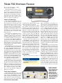
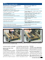
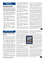
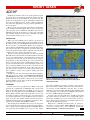
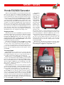
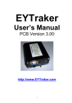
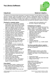
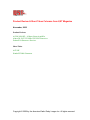
Product Review & Short Takes Columns from QST Magazine
November, 2002
Product Reviews
ACOM 1000 HF + 6-Meter Linear Amplifier
Alinco DJ-296T 222 MHz VHF FM Transceiver
Palstar R30 Shortwave Receiver
Short Takes
ACE-HF
Honda EU2000i Generator
Copyright © 2002 by the American Radio Relay League Inc. All rights reserved.
PRODUCT REVIEW
ACOM 1000 HF + 6-Meter Linear Amplifier
Reviewed by Mark Wilson, K1RO
QST Publisher
ACOM caught the attention of US
hams with the 1999 introduction of the
ACOM 2000A, a rugged, legal-limit
autotune HF amplifier with a current list
price of $5895. The 2000A, reviewed in
the May 2000 QST, received high marks
for its quiet, effortless operation.
ACOM introduced a second—and significantly different—amplifier to the US
market last year. The ACOM 1000 uses a
single Svetlana 4CX800A (GU74B) tube
and is rated at 1000 W output (PEP or
continuous carrier with maximum key
down times of 15 minutes on, 3 minutes
off). For higher duty cycle operation, an
auxiliary fan is recommended. The 1000
is manually tuned, covering 160 through
6 meters with a broadband tuned input
circuit and a pi-L output circuit. Marginal
antennas are no problem—the output circuit works with up to 3:1 SWR. The
power supply is built-in, and the amplifier includes extensive monitoring and
protection features. QSK (using a vacuum
relay) is standard. The amplifier weighs
49 pounds. It carries a list price of $2750.
Most of the front panel is very familiar—an ON/OFF switch, TUNE and LOAD
controls, and a BAND switch. Metering
and control functions are handled by a
backlit LCD and OPERate, PREVious and
NEXT pushbuttons. The top half of the
LCD always displays PEP output power.
The bottom half serves several functions.
It displays additional information about
operating parameters, serves as a tuning
aid, and shows troubleshooting information from the automatic protection system.
Rear-panel connections are equally
simple. The 1000 uses a phono jack labeled
KEY IN for the T-R key line (ground to
transmit) and SO-239s for RF INPUT and
RF OUTPUT. There’s another phono jack
labeled KEY OUT . According to the
manual, you can use it to improve T-R
switching with transceivers that have a TXinhibit, mute or similar input. If your station isn’t set up to use this feature, no problem—everything works just fine without
it. A ground post, fuse holders and LINE
power switch round out the back panel.
Using the ACOM 1000
Our amplifier was shipped with tube
and transformer installed. It’s shipped
ready to operate from 240 V ac, but you
can change primary taps for 200-240 V
or 110-120 V in 10-V steps. The manual
suggests contacting ACOM for details.
We supplied the appropriate 15-A,
250-V plug for the line cord. As required
by FCC rules, 10 and 12 meter operation
is disabled. If you provide a copy of your
Amateur Radio license at purchase time,
ACOM will provide details on enabling
operation on these bands.
There are two power switches. The one
on the real panel controls all power to the
amplifier; when it’s off, nothing is powered. The manual refers to the one on the
front panel as controlling on line or off
line states. When it is off, the tube and
blower functions aren’t powered but the
microprocessor control circuitry and
LCD are to provide access to some information screens and control functions.
There is a 2.5 minute warmup period
when you first turn the amplifier on. The
LCD displays “Warming Up” and counts
down from 150 seconds during this period. When the warmup period is over,
you can place the amplifier in-line using
the OPER button. One of the first things
I noticed about the ACOM 1000 is that it
is exceptionally quiet. I held my hand
over the blower exhaust the first time to
make sure it was running.
Tune-up is different from other ampli-
Bottom Line
Quiet, easy to operate and compact, this 160-6 meter 1000 W amplifier is a great companion for your HF
+ 6-meter transceiver, at home or in
the field.
Brennan Price, N4QX
From November 2002 © ARRL
Assistant Technical Editor
fiers that I’ve used. First, preset the TUNE
and LOAD controls according to a chart
in the manual. Next, press the PREV and
NEXT buttons simultaneously. This inserts a 6-dB attenuator at the input and
puts the LCD into the TRI (true resistance
indicator) mode. The attenuator allows
you to tune up the amplifier at reduced
power without adjusting your transceiver.
Apply drive and adjust the LOAD control
until the V-shaped marker is centered on
the scale. Arrows show which way to
turn the LOAD control. Then turn the
TUNE knob to peak forward power and
you’re done. The ACOM easily tuned up
to 1000 W output on each band with drive
power between 60 and 70 W.
You can also select the TRI scale without the input attenuator and manually
adjust your transmitter power to 20 W or
less. Or if you transmit at normal power
and the amplifier isn’t tuned, the protection circuitry will automatically select the
attenuator and TRI mode.
During normal operation, the PREV
and NEXT buttons are used to switch the
LCD to show important operating parameters including forward, reflected and
output power, antenna SWR, drive power,
plate current, high voltage, peak plate RF
voltage, screen current, dc power input
and exhaust air temperature. The LCD’s
brightness and contrast are adjustable. It’s
best viewed straight-on; I found the display a little hard to read with the amplifier is on a small stand to the lower left
of my operating position.
The 1000 includes a number of protection features aimed at making the amplifier idiot-proof and accident-proof. If
you come close to exceeding normal operating parameters (say, excessive an-
[email protected]
Table 1
ACOM 1000, serial number 020136
Manufacturer’s Claimed Specifications
Measured in the ARRL Lab
Frequency range (US units): All amateur frequencies, 1.8 to 54 MHz.
As specified.
Power output: 1000 W PEP, all modes and continuous or modulated carrier.
As specified for SSB and CW.
Driving power required: Not specified.
70 W typical.
Input SWR: Less than 1.3:1.
As specified.
Output matching: Up to 3:1 SWR.
Not tested.
Spurious signal and harmonic suppression: 50 dB below rated output or
greater for HF; 66 dB for 6 meters.
53 dB, worst case on HF; 63 dB on 6 meters.
Meets FCC requirements.
Intermodulation distortion (IMD): –35 dB.
–44 dB. See Figure 1.
Primary power requirements: 100-120 V (in three user-settable taps) and 170-264 V ac (in five user settable taps).
Size (HWD): 7.2 × 16.6 × 14 in; weight, 48.5 pounds.
0
Reference Level: 0 dB PEP
–10
–20
–30
–40
–50
–60
–70
–80
–10
–8
–6
–4
–2
0
2
4
Frequency Offset (kHz)
6
8
10
Figure 1—Worst-case spectral display of
the ACOM 1000 HF + 6-meter linear
amplifier during two-tone intermodulation
distortion (IMD) testing. The worst-case
third-order product is approximately
44 dB down, and the worst-case fifthorder product is approximately 55 dB
down. The transmitter was being
operated at 1000 W output at 14.020 MHz.
Figure 2—The RF circuitry inside the ACOM 1000. The front panel is to the right.
tenna SWR), the LCD flashes a warning.
If safe operating parameters are exceeded,
the 1000 switches to standby mode and
displays an error message, such as, **REFLECTED POWER**. One interesting
feature is the Auto Operate mode. If you
have Auto Operate enabled and the amplifier faults, it will reset the amplifier to the operate mode automatically. Of
course it will trip again if the problem
(excessive reflected power, excessive
drive power or whatever) persists.
The amplifier also displays information about internal faults—when it occurred and the type of fault—as an aid
during troubleshooting. The amplifier
stores information about the seven most
recent faults. Error codes are a bit cryptic—for example, 1ASB2E indicates that
a 24 V dc power supply fault was detected
in standby after the warmup period. But
with a little patience, you can decode
them using information in the manual.
Other protection features allow the
Figure 3—The power supply circuitry inside the ACOM 1000.
From November 2002 © ARRL
amplifier to withstand up to 300 W reflected power (we didn’t test it above
250 W), short duration overdrive spikes,
low ac line voltage, and up to 15% line
voltage spikes. These last two features
make the 1000 attractive for DXpeditions
or Field Day operation.
Speaking of DXpeditions, the frequency coverage and compact package
make the ACOM 1000 attractive for travelers. NCJ “Contest Expeditions” columnist Kenny Silverman, K2KW, notes that
he has taken an ACOM 1000 on three
contest operations to 6Y5 (Jamaica).
“The amp is a really great one-suitcase
DXpedition amp,” he says. “With a Pelican 1650 carrying case and custom highdensity foam, the package weighs in at
70.5 pounds. Most airlines have a 70pound limit, and there has never been an
issue at the check-in counter.”
Kenny also noted that his pre-production model produced receiver birdies on
6 meters. ACOM came up with modifications to suppress the birdies and indicates that all US production models were
shipped with the mods in place. That was
the case with our amplifier, and we no-
ticed no 6-meter birdies in the Lab or
during operation.
On the Air
I used the ACOM 1000 with my ICOM
IC-746 transceiver and gave it a workout
on all the bands. Thanks to the quiet fan
and vacuum relay, it adds little to the
noise in my station. My antennas aren’t
perfect, and I appreciated the wide tuning range. In particular, my Cushcraft X7
multiband beam works on 17 and 12
meters, but the SWR is just over 3:1 on
those bands. I was able to operate the
ACOM at nearly its rated output without
exceeding any of the operating parameters. My dipole for 40 meters is cut for
the low end of the band, but I had no
trouble using it on the phone end without a tuner. The one challenge that was
just too great was using a low 80-meter
dipole cut for CW on the phone band.
I really didn’t miss the 500 W that the
1000 gives up to legal-limit class amplifiers, and I consider 6 meter operation a
huge plus. The TRI tuning indicator made
tune-up a snap, once I got used to using
it. I appreciated the extensive protection
Alinco DJ-296T 222 MHz
VHF FM Transceiver
Reviewed by Dan Henderson, N1ND
Contest Branch Manager
For several years, I served as Quartermaster for all club equipment as well as
one of the control operators for its very
active VHF repeater. It was necessary to
delve into the world of 222 MHz equipment, as that was the chosen means for
remote control of the equipment. At that
time I remember trying to find a handheld
that would be simple to operate and reliable at a reasonable cost, but nothing was
available at that time. So, I settled on an
Alinco mobile radio for the task at hand.
Today, there would be an easy solution—the Alinco DJ-296T 222 MHz VHF
FM transceiver. The DJ-296T is the latest addition to the popular Alinco family
of products for VHF/UHF enthusiasts. It
incorporates many of the features from
the popular DJ-596T—Alinco’s successful 2-meter/70-cm dual-band handheld—
into a user-friendly, easy-to-use product.
Over the years the single biggest negative comment many of us hear from active hams is that the newer radios, with
all their “bells and whistles,” are too comFrom November 2002 © ARRL
plicated to operate with instructions too
difficult to understand. Perhaps the strongest endorsement I can give to the
DJ-296T is that within about 10 minutes
of removing it from its box, I was able to
get on the air. Consider that the only
handheld of any kind I own still has
thumb-wheels for dialing in the frequency, a slide switch to adjust the offset
and doesn’t have tone-squelch … well,
the DJ-296T can’t be too complicated if
you can teach this old dog a new trick or
two easily.
The first thing I noticed was that a
single DIAL knob was used to adjust all
settings—from volume and squelch to the
various user functions. Turning it without the FUNCTION , VOL or SQL key
pressed, it operates the VFO. I quickly
learned that to adjust volume and squelch
all you had to do was press the VOL or
SQL buttons and turn the DIAL. With that,
I was set to operate the rig.
Unlike many available HTs on the
market, where you may have to hold
down several buttons to get to the desired
FUNCTION control, the DJ-296T is about
circuitry and never felt that I needed to
worry about hurting anything if I made a
common mistake like changing bands and
forgetting to change the band switch.
Fellow HQ staffer Dennis Motschenbacher, K7BV, gave the ACOM 1000 a
good workout on 6 meters during the
ARRL September VHF QSO Party. New
to 6 meters, during the summer he had
gained a lot of experience on the band
with 100 W and a 7-element Yagi. The
ACOM 1000 performed flawlessly during the contest, allowing him to make a
number of marginal QSOs on scatter and
other weak signal modes. The extra power
helped attract the attention of weaker stations and extended his normal coverage
area. “I want one,” he says.
If you’re looking for a companion
amplifier for your HF + 6-meter radio,
or if you are looking for a Field Day or
expedition amplifier, this is definitely one
to consider.
US Distributor: ACOM International,
71 West St, Medfield, MA 02052, tel
508-359-5990; fax 508-359-5989; www.
hfpower.com. Manufacturer’s suggested
retail price: $2750.
Bottom Line
Alinco’s newest fullpower, single band
handheld provides affordable access to a band
more and more FM enthusiasts are flocking to:
1.25 meters. The DJ296T is a worthy successor to its older brother,
the DJ-280.
Table 2
Alinco DJ-296T, serial number M000861
Manufacturer’s Claimed Specifications
Measured in the ARRL Lab
Frequency coverage: Receive, 216-250, transmit, 222-225 MHz.
Receive and transmit, as specified.
Power requirements: 7-16 V dc; receive, 0.2 A;
transmit, 1.2 A (max, high power).
Receive, 0.21 A (max volume, no signal);
transmit, 1.1 A, tested at 13.8 V.
Size (height, width, depth): 4.9 × 2.2 × 1.6; weight, 13.2 ounces.
Receiver
Receiver Dynamic Testing
Sensitivity: 12 dB SINAD, 0.25 µV.
12 dB SINAD, 0.16 µV.
Two-tone, third-order IMD dynamic range: Not specified.
20 kHz offset from 223 MHz, 58 dB*,
10 MHz offset from 223 MHz, 71 dB.
Adjacent-channel rejection: Not specified.
20 kHz offset from 223 MHz, 58 dB.
Spurious response: Not specified.
IF rejection, 123 dB; image rejection, 77 dB.
Squelch sensitivity: Not specified.
At threshold, 0.06 µV.
Audio output: 200 mW at 10% THD into 8 Ω.
202 mW at 10% THD into 8 Ω.
Transmitter
Transmitter Dynamic Testing
Power output: With batteries, 4.5 W high, 0.8 W low;
with external dc (13.8V), 5 W high, 0.8 W low.
Batteries: 4.5 / 1.1 W; external dc, 5.7 / 1.1 W.
Spurious signal and harmonic suppression: 60 dB.
67 dB. Meets FCC requirements for spectral purity.
Transmit-receive turnaround time (PTT release
to 50% of full audio output): Not specified.
Squelch on, S9 signal, 175 ms.
Receive-transmit turnaround time (“tx delay”): Not specified.
100 ms.
*Measurement was noise limited at the value indicated.
as simple as it gets. Pressing a single
FUNCTION key, strategically located at
the top of the right-side column of buttons, lets you access the wide-range of
features that are well marked on the keypad. The DIAL knob allows you to change
the settings for the various functions once
the proper FUNCTION key has been selected. For example, to change the tonesquelch setting simply requires that you:
a) press the FUNCTION key, b) press the
TSQ button (which is clearly marked), c)
turn the DIAL until you display the desired TSQ tone, d) press the TSQ key
again to activate the function and e) press
the FUNCTION key to exit the process.
I had the opportunity to test the
DJ-296T not only in a city setting, but in
the mountains as well. As you would expect, the 4.5-W high power setting was
needed to get the signal through in the
mountains. But in the city, 280 mW was
adequate for line-of-sight communications. Handheld operation with a rubberduck antenna can be marginal in lessthan-perfect locations, but when I
attached a quarter-wave magnetic mount
antenna to the radio, I was pleasantly
pleased with the results. The quality of
the received audio was sharp and clear,
and the friends with whom I spoke on
the air all reported that I sounded like
me—a pretty good testament for the quality of the signal.
The 140-channel programmable
memory provides more than ample storage for the limited number of 222 MHz
repeaters in my area. Someone who travels frequently and used this band would
have no problem making sure they have
the proper frequencies, tones and codes
programmed and readily available in their
radio. Programming and scanning
memory channels is a simple five-step
process. The DJ-296T also allows you to
program in the full-range of items for
each stored channel—from frequency and
offset to power level, DCS and TSQ settings.
I was fascinated with the three “special
features” that are also found with the DJ596T and other more recent Alinco products—“Theft Alarm,” “External Control”
and “Mosquito Repel.” Time did not permit me to fully explore how the radio repelled bugs, and to tell the truth, I am not
sure that I want to be the guinea pig to see
if the Mosquito Repel really worked!
Alinco also provides instructions for
cloning, which allows you to connect the
rig to another and copy the settings, including memory channels, and for packet
operation. Additional features incorporated into this radio include the ability to
name memory channels, an auto power
off function (for those of us who forget
to turn their rig off), a time out timer (for
those of us who can get long-winded) and
tone burst (necessary for accessing some
European repeaters, but somewhat superfluous on a 222 MHz machine, since 1.25
meters is only available to hams in ITU
Region 2).
The bells and whistles are great and
can allow an amateur to more efficiently
utilize the radio. But if you are looking
for a simple, easy to use radio for the 222
MHz band, the DJ-296T can provide you
with the basic package with a minimum
amount of time spent reading instructions
and programming a radio.
Historically, many amateurs have not
utilized the 222 MHz band because of the
availability and cost of equipment. The
Alinco DJ-296T goes a long was towards
resolving those concerns. As a former
ARES District EC, I know that we used
1.25 meters for command communications. The DJ-296T should serve quite well
in that respect. Whether you are interested
in emergency communications or simply
enjoying some operating fun, the DJ-296T
can provide you with a simple way to expand your bands at an affordable price.
Manufacturer: Alinco Inc., Shin Dai
Building 8F, 1-2-6 Doujimahama, Kitaku,
Osaka 530-0004, Japan. Alinco’s US distributor is ATOC Amateur Distributing
LLC, 23 S High St, Covington, OH
45318; tel 937-473-2840; fax 937-4732862; [email protected]; www.alinco.
com. $179.95.
From November 2002 © ARRL
Palstar R30 Shortwave Receiver
Reviewed by Brennan Price, N4QX
Assistant Technical Editor
The Palstar R30 first came to our attention when it received very favorable
reviews in the shortwave listening community. The moderately priced receiver
was praised for outstanding performance
for a radio of its size and price class.
Wanting to know what all the fuss was
about, we ordered one right away.
Looks Can Be Deceiving
Out of the box, the R30 doesn’t look
like other modern dedicated receivers. It
has a dearth of user controls on the front
panel, but those that are there are easy to
operate. I was able to tune local AM
broadcast stations on the R30 within a
half minute of removing it from the box.
Just plug in the included ac adapter, stick
something into the antenna outlet in the
rear, turn the power on, turn the tuning
knob and enjoy.
The front panel of the R30 has a mere
nine controls: two knobs and seven
pushbuttons. The functions of all of these
controls are intuitive, and there is no need
to consult the manual for the most basic
of operations. The OFF/AF GAIN knob
controls power and volume. I did not turn
this knob too far counterclockwise, as the
internal speaker is quite powerful. Users
in most high-noise environments will find
the R30 useable there.
The TUNE knob on the right hand side
of the radio feels sturdy to the touch and is
easy to use. To the left of the knob, the label “PUSH 20/500 Hz” indicates how to
switch between the slow and fast tuning
rates. At the slow setting, the tuning rate is
20-100 Hz per step, depending on how fast
the knob is turned. When the user pushes
the knob to activate the fast setting, the tuning rate varies from 100-500 Hz per step.
Users will find that it takes only a little practice to fine tune the desired signals.
Tuning knob too slow for you? No
problem. To the right of the tuning knob
are up and down arrow buttons, which
increase or decrease frequency in 0.5
MHz steps. Holding these buttons down
repeats the step rapidly and automatically.
Even though one of my first thoughts
was, “No direct frequency entry—bummer,” I can’t say I missed it. Tuning the
R30 was easy and fun.
Those Other Five Buttons
The five buttons below the easy-to-read
LCD frequency display round out the front
panel controls. The MODE key toggles
between AM and lower and upper sideband. CW may be detected by dialing a
display frequency just above (using LSB)
From November 2002 © ARRL
or below (using USB) the desired signal
until the desired note is reached.
The ATT, BW and AGC keys trigger
three features to help increase the intelligibility of the desired signal. ATT activates a 10-dB attenuator, indicated by an
LED above the button. AGC toggles between fast (for CW reception) and slow
(for most other reception) automatic gain
control response time. The BW key
switches between wide and narrow bandwidth settings. The R30 is available with
optional Collins 455 Hz mechanical
fiters; our model had them installed.
The last of the front panel keys is used
to call up MEMory settings and enable storage of frequencies into the R30’s non-volatile memory bank. Up to 100 frequencies
and all associated settings (mode, bandwidth, AGC and attenuation) can be stored.
There is no alphanumeric labeling capability, and the only way to delete a memory
is to overwrite it. Users who like storing a
lot of frequencies may find this inconvenient, but the R30 is not designed to be a
scanner—it’s designed to be a tuneable
receiver. And it receives very well.
Nice Numbers!
Taking a look at the test results in
Bottom Line
Palstar has produced an impressive portable receiver at a very attractive price.
Table 3, the R30 does very well for a receiver of its price class. The blocking and
third order intermodulation distortion
dynamic range measurements registered
a very credible 108 and 90 dB, respectively, at 14 MHz. While these numbers
do not approach those of the receivers in
high-end amateur transceivers, they do
compare with some mid-grade ham rigs,
and are almost hard to believe given the
low price of the radio. Time spent listening to the evening mishmash of European
broadcasters and North American hams
from 7.1 to 7.3 MHz will put any rig’s
dynamic range to the test. The R30 passed
this test with flying colors; I found I could
successfully decipher any signal I wanted
to listen to, with pleasant audio from the
internal speaker.
A quick glance at the rear panel shows
that the user need not be restricted to the
internal speaker. A ¼-in mono jack can feed
any speaker with an impedance of 8 Ω and
a power handling capability of at least
3 W. What’s more, the R30 can be used in
conjunction with an external transmitter
through the MUTE RCA jack. Someone
wanting to put a QRP transmitter to the test
in the field may consider using the very
light (just over 2 pounds) R30 as a receiver.
In addition to these jacks and the 50
and 500-Ω antenna connections, the rear
panel contains an on/off switch for the
front display lamp and a switch to supply
12 V dc through the coaxial antenna connector to an active antenna. Users without such antennas will want to keep this
Figure 4—The back
panel of the Palstar
R30. In addition to the
antenna connectors
and the audio and
control jacks, the
display lamp switch is
back here. Keep the
12 V dc switch blocked
unless you need to
send power down the
coaxial cable to an
active antenna.
Table 3
Palstar R30, serial number 01840
Manufacturer’s Claimed Specifications
Measured in the ARRL Lab
Frequency coverage: Receive, 0.1-30 MHz.
Receive, as specified.
Modes of operation: AM, SSB, CW.
As specified.
Power requirements: 0.6 A (max), 12 V dc.
1.2 A (max volume, no signal), tested at 13.8 V dc.
Size (HWD): 2.6 × 8.3 × 7.7 inches; weight, 2.2 pounds.
CW/SSB sensitivity (10 dB S/N): 0.1-30 MHz, 0.5 µV.
Noise floor (MDS): 1.0 MHz, –126 dBm; 3.5 MHz, –129 dBm;
14 MHz, –127 dBm.
AM sensitivity (10 dB S/N): 0.1-2 MHz,
0.6 µV; 2-30 MHz, 0.5 µV.
AM narrow, test signal modulated 30% with a 1-kHz tone,
10 dB (S+N)/N: 1.0 MHz, 1.4 µV; 3.8 MHz, 2.4 µV.
Blocking dynamic range: Not specified.
3.5 MHz, 105 dB;* 14 MHz, 108 dB.*
Two-tone, third-order IMD dynamic range: Not specified.
Two-tone, third-order IMD dynamic range:
3.8 MHz, 91 dB*; 14 MHz, 90 dB.
Third-order intercept: Not specified.
Third-order intercept: 3.8 MHz, +12.6 dBm;
14 MHz, +11.0 dBm.
Second-order intercept point: Not specified.
+52 dBm.
Audio output: 2 W at 2% THD into 8 Ω.
3.6 W at 2% THD into 8 Ω.
IF/audio response: Not specified.
Range at –6 dB points, (bandwidth): USB: 329-2911 Hz
(2582 Hz); LSB: 324-3095 Hz (2771 Hz); AM: 3402512 Hz (2172 Hz).
Spurious and Image rejection: Not specified.
IF rejection: 68 dB; image rejection: 86 dB.
*All dynamic range measurements were taken using the ARRL Lab standard spacing of 20 kHz.
Third-order intercept points were determined using S5 reference.
Figure 5—The user can take the R30 on the road by installing 10 AA batteries. After the top panel is carefully removed—notice the
wires running from the PC board to the speaker—the metal restraining strap is removed with a screwdriver (left). It is pulled back to
allow access to the battery compartment (right).
switch blocked. Finally, a LINE AUDIO
jack allows for output to a tape recorder.
How Do I Power Thee? Let Me
Count The Ways.
The R30 comes with an ac adapter.
The adapter worked, but we found it to
be somewhat noisy in the ARRL lab. Users with a sensitivity to such noise may
wish to use one of the other options: an
external regulated dc power supply or 10
1.5 V AA batteries.
The battery compartment is inside the
R30, and access requires removing the
cover. Four Phillips head screws hold the
cover in place. Users will want to avoid
yanking the cover from the radio, lest the
speaker on the top panel be loosened from
the wires connecting it to the PC board.
Once the panel is removed, another screw
is removed to allow removal of a metal restraining bar and access to the compartment. This is a convoluted procedure, but
it has some advantages: the batteries are
securely held in place, and there are no external battery doors to lose. Further, if our
experience is any indication, the user will
not have to change batteries very often.
Conclusion
The R30 is a very good MF and HF listening radio. It is light, portable and userfriendly. It is also inexpensive. Not all hams
will be in the market for a receive-only radio, but those who are may wish to pay attention to the praise the SWL community
has bestowed on the Palstar R30.
Manufacturer: Palstar Inc, 9676 N
Looney Rd, PO Box 1136, Piqua, OH
45356; tel 937-773-6255; fax 937-7738003; [email protected]; www.
palstarinc.com. $495 standard; $575 with
Collins mechanical filters installed.
From November 2002 © ARRL
Going Once,
Going Twice . . .
SOLICITATION FOR PRODUCT
REVIEW EQUIPMENT BIDS
In order to present the most objective reviews,
ARRL purchases equipment off the shelf from
dealers. ARRL receives no remuneration from
anyone involved with the sale or manufacture
of items presented in the Product Review,
Short Takes or New Products columns.—Ed.
The ARRL-purchased equipment listed
below is for sale to the highest bidder. Prices
quoted are minimum acceptable bids, and are
discounted from the purchase prices. All
equipment is sold without warranty.
Alinco DJ-X2000 wide range scanning
receiver, serial number T000617 (see
“Product Review,” Apr 2002 QST).
Minimum bid: $335.
ICOM IC-V8000 VHF FM transceiver,
serial number 01825 (see “Product Review,” Jul 2002 QST). Minimum bid:
$110.
Yaesu FT-7100M dual-band FM mobile
transceiver, serial number 1D040208
(see “Product Review,” Aug 2001 QST).
Minimum bid: $200.
ICOM PS-125 switching power supply,
serial number 01819 (see “Product
Review,” Sep 2002 QST). Minimum
bid: $200.
NEW BOOKS
INDEPENDENT ENERGY GUIDE—
ELECTRICAL POWER FOR HOME,
BOAT & RV
By Kevin Jeffrey
Published by Chelsea Green Publishing,
White River Junction, Vermont. Paperback,
7×9 inches. ISBN 0964411202; 256 pp,
$19.95. Available from ARRL (order no.
8601) by calling toll-free in the US 888-2775289 or 860-594-0355; fax 860-594-0303;
or on the ARRLWeb, www.arrl.org/shop.
Reviewed by Mike Gruber, W1MG
In the Independent Energy Guide Kevin
Jeffrey takes the reader from the basics of
energy and electricity to complete system
considerations. While most amateurs might
already know electrical fundamentals, they
may not be as familiar with some basic
physics, especially with regard to power
and energy. This important information is
presented at the beginning of the book in
an easy to understand manner. The technical level is about that of a typical FCC license exam. If you’re not interested in this
level of technical detail don’t worry. Jeffrey quickly moves on to renewable energy
sources in Chapter 3.
Jeffrey devotes a chapter each to solar,
wind and water power. I find the treatment
comprehensive with a good balance beFrom November 2002 © ARRL
Kenwood TS-2000 with UT-20 1.2 GHz
module, serial number 20800064 (see
“Product Review,” Jul 2001 and Sep
2002 QST). Minimum bid: $1440.
Sealed bids must be submitted by mail
and must be postmarked on or before
December 2, 2002. Bids postmarked after the
closing date will not be considered. Bids will
be opened seven days after the closing postmark date. In case of equal high bids, the
high bid bearing the earliest postmark will
be declared the successful bidder.
In your bid, clearly identify the item you
are bidding on, using the manufacturer’s
name and model number, or other identification number, if specified. Each item
requires a separate bid and envelope. Shipping charges will be paid by ARRL. Please
include a daytime telephone number. The
successful bidder will be advised by telephone or by mail. Once notified, confirmation from the successful bidder of intent to
purchase the item must be made within
two weeks. No response within this period
will be interpreted as an indication of the
winning bidder’s refusal to complete the
transaction. The next highest bidder will
then have the option of purchasing the item.
No other notifications will be made, and
no information will be given to anyone
other than successful bidders regarding the
final price or the identity of the successful
bidder. If you include a self-addressed,
stamped postcard with your bid and you are
not the high bidder on that item, we will
return the postcard to you when the unit
has been shipped to the successful bidder.
Please send bids to Bob Boucher, Product Review Bids, ARRL 225 Main St,
Newington, CT 06111-1494.
tween the practical and theory. Each energy source discussion includes an evaluation of system efficiency, available hardware options and associated electrical
characteristics. The installation discussion
covers home, boat and RV as appropriate.
In addition, peripheral system
hardware, such as batteries, controllers, monitors, batteries and
alarms are also discussed. Jeffrey ends each of these chapters
with tips on installation and operation followed by a comparison of the particular energy
source being considered. There
are also similar tips and comparisons in appropriate reaming
chapters.
(Note: Jeffrey only covers photovoltaic
solar panels in this book. There is no discussion of solar thermal panels such as
those used to heat hot water.)
The next three chapters cover alternators and (gasoline or diesel fueled, engine
driven) portable generators and/or dc
chargers and ac to dc chargers. While I’m
more familiar with these devices, I nonetheless found this discussion informative.
The technical content and level of detail is
similar to that in the previous treatment of
the more exotic renewable energy sources.
The difference between standard and high
output alternators is well explained, and an
exploded view of a typical alternator is in-
cluded. There is also good information on
portable generators, which should interest
anyone considering one for a home emergency ac power source
The next two chapters are devoted to ac
systems. They cover inverters, which convert dc to ac, and direct ac power
sources such as gen-sets. Gensets are similar to the portable
generators but are permanently
mounted units without handles.
Next are chapters that detail the
storing and monitoring electrical power. I particularly liked
the battery chapter; I thought it
was well done and loaded with
useful information. The next
chapter on energy conservation
includes an excellent discussion on energy
saving appliances. And finally, the last
chapter provides a step-by-step guide to selecting and sizing the components of an independent energy system.
Systems such as these are obviously not
for everyone. So, who might benefit from
the Independent Energy Guide? I find it
worthy of consideration by anyone wanting
such a system for a boat, RV or home. In
fact, anyone just having an interest in an independent power system might enjoy it.
Although I wish it had included a chapter on fuel cells, I found the Independent
Energy Guide to be the “soup to nuts” overview I was looking for.
Palstar R30 shortwave receiver with
Collins mechanical filters, serial number 01840 (see “Product Review,” this
issue). Minimum bid: $385.
Yaesu VX-7R tri-band handheld transceiver, serial number 2G022193 (see
“Product Review,” Oct 2002 QST).
Minimum bid: $270.
Alinco DJ-296T 222 MHz handheld
transceiver, serial number M000861
(see “Product Review,” this issue).
Minimum bid: $120.
ICOM IC-746PRO HF/VHF transceiver, serial number 01484 (see “Product Review,” May 2002). Minimum bid:
$1100.
ACOM 1000 HF + 6-meter linear amplifier, serial number 020136 (see “Product Review,” this issue). Minimum bid:
$1650.
Ranger RCI-2970DX 10/12-meter transceiver, serial number T1M00426 (see
“Product Review,” Oct 2001 QST).
Minimum bid: $290.
SHORT TAKES
ACE-HF
Normally we would recruit one of our propagation experts
to review a piece of propagation-prediction software. For this
Short Take, however, we’re making an exception because this
product is not designed for experts (although it includes features experts would appreciate). On the contrary, ACE-HF is
one of the first applications of its type written primarily for
the average ham.
Most of us are not propagation gurus and we would rather
chew aluminum foil than grapple with an expert-level propagation program such as VOACAP. ACE-HF is based on the
VOACAP engine, but the interface to you, the user, is friendly
and instantly intuitive. In other words, ACE-HF is propagation-prediction software for the rest of us!
Just the Facts
When you order ACE-HF you are asked to specify the approximate latitude and longitude of your station. That’s because
the software arrives on a CD-ROM with the transmitter location
file on a separate 31/ 2-inch diskette. Whenever you attempt to
run a prediction, ACE-HF looks for this location file in the floppy
drive. One location file is adequate for most hams, but if you
need to run predictions that assume a different station location,
you’ll need to order a new location file ($15 each).
Before you run your first prediction, you have to tell ACEHF a little about yourself. Click on the INPUTS button and you’ll
see a screen similar to Figure 1. In this window you enter your
output power and select the type of antenna you are using for
the prediction. A drop-down menu gives you several antenna
choices. You can use the generic default antenna values, or set
up your own (I usually choose “horizontal dipole”). Next you
select your target (DXCC entity, US city—you name it) and
the type of antenna that might be on the other end of the circuit. You can select a worst-case scenario (“short whip”) or be
more optimistic (“Yagi”). Once again, I usually pick “horizontal dipole.”
Finally, you enter the current Smoothed Sunspot Number,
which you can get on-line at www.nwra-az.com/spawx/
ssne24.html and many other sources, followed by the month,
mode, local noise-level profile (“rural,” in my case) and the
desired reliability (10 to 90%). Click the RUN PREDICTIONS
button and you’re on your way.
The Results
For this review I ran a prediction for a RTTY circuit from
Connecticut to Guadeloupe at 0200 UTC with a desired reliability of 50%. My output power was 100 W. As you can see in
Figure 2, the green portion of the ACE-HF display is telling me
that I’m likely to find the path I want on 20 meters. I can re-cast
the results according to needed power gain, expected S-unit levels, signal strength at the receiver (in dBµV) and even elevation
angle. I can also open smaller auxiliary windows that show a
maximum usable frequency plot (MUF), best frequency chart,
signal-to-noise summary and reliability summary.
The fun thing about ACE-HF is that you can vary the parameters to fit just about any scenario you can imagine. For instance,
I have a devil of a time working South Korea on RTTY. When I
ran a prediction with ACE-HF, it was easy to see why. AssumSteve Ford, WB8IMY
Figure 1—The ACE-HF input screen.
Figure 2—ACE-HF shows reliability predictions on the
Connecticut-to-Guadeloupe path by band according to the
selected time of day.
ing that the South Korean station is sporting a Yagi, my best
hope in the month of August (when this review was written) is
on 17 meters at about 1200 UTC—and that “hope” is only a
reliability of 8%! In December ACE-HF predicts reliability will
reach a whopping 13% on 10 meters at 2300 UTC. No wonder I
don’t have a RTTY QSL from South Korea.
Of course, these are only predictions. Any HF operator will
tell you that miracles do indeed occur on supposedly impossible paths. ACE-HF gives you an accurate idea of what to
expect, but that doesn’t mean that you shouldn’t turn on your
radio and check the bands anyway.
Manufacturer: ACE-HF, 2218 N Tuckahoe St, Arlington,
VA 22205; tel 703-241-2661; www.acehf.com. $99. System
requirements: Pentium 100 or better, Windows 95/98/98SE/
ME/NT4/2000/XP, 32 MB RAM.CD-ROM drive.
QST Editor
[email protected]
From November 2002 © ARRL
SHORT TAKES
Honda EU2000i Generator
When I worked VP8THU on South Sandwich Island earlier
this year, the contact was an all-time new DXCC entity for
me. And as I planned to go to the International DX Convention in Visalia this past spring, I learned that among the programs was a presentation on the VP8THU trip by Trey, N5KO.
Trey’s Visalia presentation included information about the
generators used by the VP8THU group. A slide in Trey’s program dramatically demonstrated how difficult it was to land
on Thule. As a result, the VP8THU group selected generators
that any one of them could carry onto the island. “Carrying”
the generators onto Thule also involved jumping from the Zodiac craft to the rock cliffs of the island. The lighter the generator, the better. Their choice was the Honda EU100i. These
little powerhouses each ran two power supplies, two Kenwood
TS-50 transceivers, two computers and a lamp or two.
Shopping for Power
Since the generator used on VP8THU was purchased in New
Zealand, I decided to first see if there was a Honda generator
site on the Web. The quick answer was yes, at www.
hondapowerequipment.com, with a link to their lightweight generators. With a quick click on the link, www.
hondapowergenerators.com/genligmod.htm, all of the US
products were right in front of me.
The Web site featured two models: EU1000i (very similar
to the one used on VP8THU) and the EU2000i. A further link
gave me a choice of two local dealers of these generators.
I went to one of the dealers to check out the generators in
person. After considering my needs, not only for emergency use,
but also for some IOTA trips planned for this summer, I chose
the EU2000i.
The Honda
EU2000i is a
2.5-horsepower
unit that provides 120 V ac
at 2000 W maximum (1600 W
“standard”). Its
dry weight is 46
pounds. The
generator measures a compact
17 × 11 × 20
inches. Honda
advertises that
this generator features “exclusive Honda Inverter Technology
to offer clean power for operating computers and other sensitive testing equipment.” Neither our Field Day radio nor our
laptop experienced power hiccups with the generator.
Almost every visitor to our operating site would ask about
our source of power. When told it was a generator, they commented on how quiet it was, and even how “cool” the generator looked. If you’re in search of a small generator, consider
the Honda EU2000i.
Manufacturer: Honda Power Equipment Group, 4900
Marconi Dr, Alpharetta, GA 30005-8847; tel 800-426-7701;
www.hondapowerequipment.com/gen.htm; $1150.
The Honda EU2000i
The EU2000i is not as light as the generator that the
VP8THU group carried ashore, but it is only 46 pounds and
has a built-in handle. It was easy to carry from the garage to
my pickup, and from the pickup to the operating site.
My first chance to use the EU2000i was on Field Day 2002.
As a part of the Valley Radio Club’s W7PXL operation for Field
Day, one of the stations was powered by the EU2000i, running a
Kenwood TS-570D/G transceiver, a Dell laptop, a Kenwood P/S
40 power supply, an MFJ keyer and a small lamp on the table.
The generator could have handled three or four times that load,
but this was a good first run.
The EU2000i sports a four-cycle engine and runs on regular
gasoline. Its fuel tank holds 1.1 gallons. With the Field Day set
up I’ve described, the tank gave us about 5 hours of operation
between refills, and the tank was never run completely dry.
Another very nice feature was the generator’s noise level.
The EU2000i was very quiet; the quietest generator among a
dozen or so being used at our Field Day site. Yes, the EU2000i
creates a muted rumble, but it is a far cry from the ear-numbing drone of most generators. We planted the EU2000i about
15 feet from the operating table, and though shielded by my
pickup, it was not objectionably loud. The specs rate the loudness of the EU2000i at 59 dB at rated load.
Mark Perrin, N7MQ
The business end of the Honda EU2000i.
55 Coachman Dr, Eugene, OR 97405
[email protected]
From November 2002 © ARRL