1
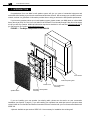
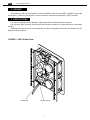
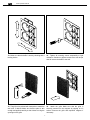
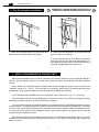
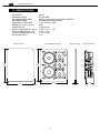
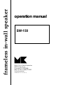
frameless in-wall speaker
operation manual
SW-150
Miller & Kreisel Sound Corporation
9351 Deering Avenue
Chatsworth, CA 91311-5858
(818) 701-7010 fax (818) 701-0369
www.mksound.com
©2001 Miller & Kreisel Sound Corp.
In-wall Operation Manual
Table of Contents
1.
2.
3.
4.
5.
6.
7.
8.
9.
10.
11.
Introduction ...................................................................................................3
Figure 1 - Major Components of the SW-150 .........................................3
Speaker Hookup .................................................................................................4
Figure 2 - SW-150 Rear View ...................................................................4
Application ..........................................................................................................4
Post Construction Installation ...........................................................................5
Mounting Speaker in Wall ..................................................................................6
Pre-Construction Installation ............................................................................8
Satellite & Subwoofer Phase Test ....................................................................8
Speaker Damage and How to Avoid It .............................................................9
If You Need Service or Assistance ..................................................................9
M&K 10 Year Warranty .......................................................................................9
SW-150 Specifications ....................................................................................10
Please complete the following:
Serial Number:
Date of Purchase:
Dealer Name:
Dealer Address:
City/State/Zip:
Country:
Invoice Number:
2
In-wall Operation Manual
1. INTRODUCTION
Congratulations! Your new M&K in-wall speaker system will give you years of unmatched enjoyment and
excitement while listening to your favorite musical and audio/video sources. We encourage you to read this owner’s
manual, as there is a great deal of information provided here to help you achieve the best possible performance.
If you have any questions about your in-wall speaker system, please contact your M&K dealer or call the M&K
factory directly at (818) 701-7010, from 8:30 AM to 5:00 PM Pacific Time, Monday through Friday. We will be happy
to help you with any question. Additional information may also be obtained on our web site: www.mksound.com or
you may send us an e-mail to [email protected].
FIGURE 1 - The Major Components of the SW-150
Foam Frame
Foam Dampening Pad
Elastic Cord
Speaker Grille
Pre-Construction
Assembly*
SW-150 In-wall Speaker
Assembly
If you are installing your new speaker into existing walls, please see the section on post construction
installation (see Section 4, page 5). If you will installing your speakers into walls that have not yet been sheet
rocked, follow the Pre-Construction Bracket Instructions that are included with your Pre-Construction Bracket Kit
SPRE-150.
*Optional: Available as part number SPRE-150. Not necessary for installation into existing wall.
3
In-wall Operation Manual
2. HOOKUP
The Positive (+) lead from your amplifier or receiver should be connected to the RED (+) INPUT terminal, and
the Negative (-) lead from your amplifier or receiver should be connected to the BLACK (-) INPUT terminal.
3. APPLICATIONS
Left, Center, and Right Channel Speaker for high performance multichannel speaker systems.
Left Surround, Right Surround, and Back Surround Channel Speakers for high-performance multichannel
systems.
Especially well-suited for use as surround speaker in systems using M&K S-150 and S-150 speakers for Left,
Right, and Center Channels.
FIGURE 2 - SW-150 Rear View
speaker wire
speaker terminal
4
In-wall Operation Manual
4. POST CONSTRUCTION INSTALLATION
!
IMPORTANT! - MAKE SURE WALL ELECTRICITY IS
TURNED OFF BEFORE STARTING INSTALLATION
1. Mark wall with the template, using a
stud finder to maintain a 2” distance from
any stud. Make sure that you are clear of
any crossbraces in the wall structure.
!
2. Cut opening precisely with a drywall
saw, drywall router, etc. Sand edges and
clean debris from installation area.
FOR STANDARD
INSTALLATION
DRYWALL
THICKNESS CANNOT
EXCEED 1.25 INCHES.
FOR THICKER
WALLS CALL
M&K SOUND.
4. Tape speaker wire to the back wall so
the end is within the opening as shown.
3. Fill in the wall space around the
speaker using the included foam strip.
The foam strip has 1” deep slits to allow
bending it into a 4-sided frame.
5. Fold the first section of the foam strip
and insert the corner through the wall
opening.
speaker wire
speaker
wire
CAUTION: Be careful when bending
and handling the strip so that you do
not rip it.
8. Mount the adhesive backed foam pad
in the wall to the left of the cutout. This
should place the foam behind the
woofers.
6. Continue folding and inserting the rest
of the foam strip into the wall opening
until the foam frame is created.
foam pad
wall opening
Note: Do not put any other acoustic filler
within the wall opening as it can interfere
with the speaker mounting.
7. Make sure that the frame is centered
within the opening.
5
In-wall Operation Manual
5. Speaker Mounting
wall opening
mounting arms
speaker wire
mounting screws (6 total)
9. Remove packing material and grille from speaker. Do
Not Remove the Elastic Cord! Make sure that the
mounting screws are flush with the front baffle as shown.
10. Angle the speaker toward the wall and slip the
bottom portion of the mounting arms into the wall
opening.
wall opening
11. Tip the unit vertically and pass the top edge of the
mounting arms through the wall opening, allowing the
unit to rest on the bottom mounting screws.
12. Center the speaker within the wall opening.
6
In-wall Operation Manual
13. Make sure that the baffle is level by checking with a
leveling device.
14. Tighten all mounting screws sequentially to light
resistance. Continue to tighten screws to an even torque
that will secure the baffle to the wall.
15. The grille ca be painted with Latex paint to match the
wall color if desired. Make sure that the paint is thin
enough and applied carefully so that it does not clog the
openings on the grille.
16. Attach the grille. Make sure that the grille is
securely mounted on the magnets by tapping on it’s
surface. Remove the grille and reposition magnets if
necessary.
7
In-wall Operation Manual
6. Pre-Construction Installation
!
IMPORTANT! - MAKE SURE WALL ELECTRICITY IS
TURNED OFF BEFORE STARTING INSTALLATION
staples
2. Attach the bracket assembly to the wall studs with
screws or nails (not included).
1. Attach the mounting strips to the pre-construction
bracket with the included sheet metal screws.
3. Run the speaker wire to the location of the bracket.
Secure the wire to one of the studs using staples or “U”
nails. Make sure that the wire is clear of the opening or
it may be damaged when the drywall is cut.
7. SATELLITE/SUBWOOFER PHASING TEST
When using a subwoofer with your SW-150, a phasing test must be performed to insure good bass blending.
This test insures optimum sound in the critical bass frequencies where your Subwoofer and Main speakers
overlap.
Play a familiar CD or DVD with steady, consistent bass content through your system. Listen carefully to the
"mid-bass" region of 75 - 125 Hz. This is the part of the spectrum where electric or string basses and drums
predominate. Then reverse the phase of either the subwoofer or BOTH Main speakers.
If your Subwoofer has a PHASE switch on its back panel, move it either from (+) to (—) or vice versa.
If your Subwoofer does not have a PHASE switch, it takes a bit more work. You will have to change the Positive
and Negative speaker inputs on the back of BOTH Main speakers.
You can do this at the back of both Main speakers, or at the Subwoofer's TO SPEAKERS terminals, but never
at both locations. The lead that was on the Positive (+) terminal should be switched to the Negative (—) terminal,
and vice versa. When switching speaker wires, take care to protect your amplifier. Make sure that the wires do
not touch each other when you are making the switch. As a safety measure, we suggest that you turn the
amplifier off before making the switch.
Now listen to the same musical passage as you did earlier, concentrating on the mid-bass region. If you hear
less bass, the original connection (or switch position) was correct. If you hear more bass, the new connection (or
switch) is correct.
8
!
In-wall Operation Manual
8. SPEAKER DAMAGE & HOW TO AVOID IT
An important factor to consider with any loudspeaker system is the potential for speaker damage. Even though
your M&K Speakers have extremely high power handling ability (especially for Main speakers), they still can be
damaged by relatively low powered amplifiers.
While very few M&K Speakers are actually returned for service, the vast majority of those returned are not for
manufacturing defects. Instead, they are returned because they have been over driven, almost always because
the amplifier or receiver used was driven into clipping distortion. This damage is considered abuse, and is not
covered under warranty.
This clipping distortion occurs when the demands of the music are greater than the amplifier's available power.
It can occur at 20 watts with a small amplifier, or at 400 watts with a large amplifier. When this happens, the
amplifier's output waveform (which resembles a smooth arc) is "clipped" off, exhibiting a flat top instead of the arc.
This "clipped" waveform contains multiples of the original amplified frequencies, sometimes at higher levels
than the original signal itself. For tweeters, this can be very damaging, as this distortion is well above the audible
range (where you are unable to hear it), and where the tweeter is most vulnerable to damage.
When an amplifier "clips", it generates a high level of high frequency energy (much higher than normal
program material) which passes through the crossover to the tweeter. This energy can overheat the tweeter in a
matter of seconds and destroy it.
When this happens, the sound becomes harsh and grating, and a break-up is often audible in the bass
frequencies. It will become uncomfortable to listen to, especially when compared to a slightly lower volume level.
When you are listening at high volume levels, be aware of the onset of clipping distortion, and turn the volume down
slightly if the sound takes on the character described above.
When tone controls or equalizers are used to boost frequencies, the problem occurs much more rapidly. Even
a small boost of low or high frequencies can easily double the power requirement and lead to amplifier clipping at
moderate levels. Therefore, you should use your tone controls judiciously, avoiding extreme boosts of the bass and
treble controls, especially when you are listening at high volume levels.
The best way to avoid speaker damage is to use common sense. Use moderate boosts of tone controls or
equalizers, at the very most. Listen carefully for any harshness and break-up, especially at high volume levels, and
turn down the volume when needed. If you cannot get enough volume, you may need to consider a higher
powered amplifier. If you have any questions about this, please contact M&K, and we will be happy to discuss it
with you.
9. IF YOU NEED SERVICE OR SET-UP ASSISTANCE
Contact your dealer or M&K with a complete description of the problem. Please have the unit's model and
serial numbers (found on the back of the cabinet), date of purchase, and your dealer's name. You can call M&K
between 8:30 AM and 5:00 PM Pacific Time, Monday through Friday, at (818) 701-7010. Alternatively, an email
can be sent to [email protected].
DO NOT RETURN YOUR SPEAKERS TO THE FACTORY FOR
SERVICE WITHOUT OBTAINING PRIOR AUTHORIZATION
10. M&K 10 YEAR WARRANTY
All M&K Satellite speakers carry a ten year limited parts and labor warranty. This warranty is transferable to
new owners up to ten years from the date of original purchase. It does not cover abuse, misuse, repairs by
unauthorized service stations, speakers without M&K serial numbers, speakers not sold by authorized M&K
dealers, and those damages in shipping or by accident. If you have any questions about the warranty, please
contact M&K.
9
In-wall Operation Manual
11 SPECIFICATIONS
IMPEDANCE:
MINIMUM POWER:
RECOMMENDED POWER:
MAXIMUM POWER:
FREQUENCY RESPONSE:
SENSITIVITY (2.83 V @ 1m):
FRONT BAFFLE:
GRILLE DIMENSION (H x W x D):
BAFFLE DIMENSION (H x W):
CUTOUT DIMENSION (H x W):
MOUNTING DEPTH:
4 ohms
25 watts RMS
amplifiers with between 25 and 400 watts RMS
400 watts RMS unclipped peaks
77 Hz - 20 KHz ± 2 dB
92dB
11 gauge steel
12.40” x 10.71” x 0.39”
12.14” x 10.45”
11.25” x 9.875”
3.16”
SW-150 Baffle (Front View)
Grille (Front View)
Grille (Side View)
SW-150 (Side View)
12.14"
12.4"
10.45"
10.71"
3.16"
0.39"
10
In-wall Operation Manual
11
SW150 MANUAL
PN # 70076
07/26/01 pt
qrk4.11