1
DENON
MULTI CHANNEL POWER AMPLIFIER
POA-3012CI
Owner's Manual
Bedienungsanleitung
ENGLISH
DEUTSCH
o SAFETY PRECAUTIONS
A
RISK OF
ELECTR~C
SHOCK
A
~ '--_-=D:....;:O::....:N=O:::..T-=--O=.:....;PE=N-=--_.....J ~
CAUTION:
TO REDUCETHE RISK OF ELECTRIC SHOCK, DO NOT REMOVE
COVER (OR BACK). NO USER·SERVICEABLE PARTS INSIDE.
REFER SERVICING TO QUALIFIED SERVICE PERSONNEL.
A
A
The lightning flash with arrowhead symbol, within an equilateral
triangle, is intended to alert the user to the presence of
uninsulated "dangerous voltage" within the product's enclosure
that may be of sufficient magnitude to constitute a risk of electric
shock to persons.
The exclamation point within an equilateral triangle is in. tended
to alert the user to the presence of important operating
and maintenance (servicing) instructions in the literature
accompanying the appliance.
WARNING:
TO REDUCETHE RISK OF FIRE OR ELECTRIC SHOCK, DO NOT
EXPOSETHISAPPLIANCETO RAIN OR MOISTURE.
CAUTION:
• The ventilation should not be impeded by covering the ventilation
openings with items. such as newspapers, tablecloths, curtains,
etc.
• No naked flame sources, such as lighted candles, should be
placed on the unit
• Observe and follow local regulations regarding battery disposal.
• Do not expose the unit to dripping or splashing fluids.
• Do not place objects filled with liquids, such as vases, on the
unit
ACHTUNG:
• Die Beluftung sollte auf keinen Fall durch das Abdecken der
Beluftungsbffnungen durch Gegenstande wie beispielsweise
Zeitungen, Tischtucher, Vorhange o. A behindert werden.
• Auf dem Gerat sollten keinerlei direkte Feuerquellen wie
beispielsweise angezundete Kerzen aufgestellt werden.
• Bitte beachten Sie bei der Entsorgung der Batterien die brtlich
geltenden Umweltbestimmungen.
• Das Gerat so lite keiner trapfenden oder spritzenden Flussigkeit
ausgesetzt werden.
• Auf dem Gerat sollten keine mit Flussigkeit gefUliten Behalter
wie beispielsweise Vasen aufgestellt werden.
I
IMPOTANT SAFETY
INSTRUCTIONS
1.
2.
3.
4.
5.
6.
7.
8.
9.
10.
11.
12.
13.
Read these instructions.
Keep these instructions.
Heed all warnings.
Follow all instructions.
Do not use this apparatus near water.
Clean only with dry cloth.
Do not block any ventilation openings.
Install in accordance with the manufacturer's instructions.
Do not install near any heat sources such as radiators, heat registers,
stoves, or other apparatus (including amplifiers) that produce heat
Do not defeat the safety purpose of the polarized or grounding-type plug. A
polarized plug has two blades with one wider than the other. A grounding
type plug has two blades and a third grounding prong. The wide blade or the
third prong are provided for your safety. If the provided plug does not fit into
your outlet. consult an electrician for replacement of the obsolete outlet
Protect the power cord from being walked on or pinched particularly at
plugs, convenience receptacles, and the point where they exit from the
apparatus.
Only use attachments/accessories specified by the manufacturer.
Use only with the cart, stand, tripod, bracket, or table
specified by the manufacturer, or sold with the apparatus.
When a cart is used, use caution when moving the cart/
.,
apparatus combination to avoid injury from tip-over.
Unplug this apparatus during lightning storms or when
l~
unused for long periods of time.
~-
(I)
14. Refer all servicing to qualified service personnel.
Servicing is required when the apparatus has been damaged in any way,
such as power·supply cord or plug is damaged, liquid has been spilled or
objects have fallen into the apparatus, the apparatus has been exposed to
rain or moisture, does not operate normally, or has been dropped.
CAUTION:
To completely disconnect this product from the mains, disconnect
the plug fram the wall socket outlet
The mains plug is used to completely interrupt the power supply to
the unit and must be within easy access by the user.
VORSICHT:
Um dieses Gerat vollstandig von der Stromversorgung abzutrennen,
ziehen Sie bitte den Stecker aus der Wandsteckdose.
Der Netzstecker wird verwendet, um die Stromversorgung zum
Gerat vbllig zu unterbrechen; er muss fur den Benutzer gut und
einfach zu erreichen sein.
FCC INFORMATION (For US customers)
1, COMPUANCE INFORMATION
Product Name: Multi Channel Power Amplifier
Model Number: POA·3012CI
This product complies with Part 15 of the FCC Rules. Operation is subject
to the following two conditions: (1) this product may not cause harmful
interference, and (2) this product must accept any interference received,
including interference that may cause undesired operation.
Denon Electronics (USA), LLC
(a 0 & M Holdings Company)
100 Corporate Drive
Mahwah, NJ 07430·2041
Tel. (800) 497-8921
2. IMPORTANT NOTICE: DO NOT MODIFY THIS PRODUCT
This product, when installed as indicated in the instructions contained
in this manual, meets FCC requirements. Modification not expressly
approved by DENON may void your authority, granted by the FCC, to use
the product
3. NOTE
This product has been tested and found to comply with the limits for
a Class B digital device, pursuant to Part 15 of the FCC Rules. These
limits are designed to provide reasonable protection against harmful
interference in a residential installation.
This product generates, uses and can radiate radio frequency energy and,
if not installed and used in accordance with the instructions, may cause
harmful interference to radio communications. However, there is no
guarantee that interference will not occur in a particular installation. If this
product does cause harmful interference to radio or television reception,
which can be determined by turning the product OFF and ON, the user
is encouraged to try to correct the interference by one or more of the
following measures:
• Reorient or relocate the receiving antenna.
• Increase the separation between the equipment and receiver.
• Connect the product into an outlet on a circuit different from that to
which the receiver is connected.
• Consult the local retailer authorized to distribute this type of product or
an experienced radio!TV technician for help.
ThiS Class B digital apparatus complies With Canadian ICES-003.
Cet appareil numerique de la ciasse Best conforme a la norme NMB-003 du
Canada.
DEUTSCH
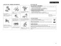
o NOTE ON USE I HINWEISE ZUM GEBRAUCH
ENGLISH
o For Europe model
DECLARATION OF CONFORMITY
We declare under our sole responsibility that this product. to which this declaration relates, is in
conformity with the following standards:
EN60065, EN55013, EN55020, EN61000-3-2 and EN61000-3-3.
Following the provisions of 2006/95/EC and 2004/108/EC Directive.
UBEREINSTIMMUNGSERKLARUNG
• Do not let foreign objects into the unit.
• Lassen Sie Kaine fremden Gegenstande in
• Keep the unit free from moisture. water,
and dust.
das Gerat Kammen.
• Halten Sie das Gartit von Feucht~kelt.
• Avoid high temperatures.
Allow for sufficient heat dispersion when
Wasser und Staub fern.
1-
f----------------j
--1
Wir erklaren unter unserer Verantwortung, da~ dieses Produkt, auf das sich diese Erklarung bezieht,
den folgenden Standards entspricht:
EN60065, EN55013, EN55020, EN61000-3-2 und EN61000-3-3.
Entspricht den Verordnungen der Direktive 2006/95/EC und 2004/108/EC.
installed in a rack.
• Vermeiden Sie hohe Temperaturen.
Beadlten SIB. dass eine ausrelchende
Beluftung gewahrleistet wird, wenn das
Garat auf ein Regal gestellt wird.
DENON Europe
Division of D&M Germany GmbH
An der Landwehr 19, Nettetal,
0-41334 Germany
• Unplug the power cord when not uSing the
unit for long periods of time.
• Wenn das Gerat langere Zeit nicht
verwendet werden soli, trennen Sie das
Netzkabel vom Netzstecker.
• Handle the power cord carefully.
Hold the plug when unplugging the cord.
• Gehen Sie vorslchtlg mit dem Netzkabel
urn.
• 00 not let insecticides. benzene, and
thinner come in contact with the unit.
• Lassen SIB das Gerat nidlt mit lnsektiziden,
Benzin oder Verdunnungsmitteln
In
Beruhrung kommen.
.-.J\\~II
U:i:~~\w
, 0:
.,...,...
HINWEIS ZUM RECYCLING:
• (For apparatuses with ventilation holes)
Halten Sle das Kabel am Stecker, wenn Sle
• Do not obstruct the ventilation holes.
den Stecker herauszlehen.
• Decken Sie den Luftungsbereich nicht abo
A NOTE ABOUT RECYCLING:
This product's packaging materials are recyclable and can be reused. Please dispose of any materials
in accordance with the local recycling regulations.
When discarding the unit, comply with local rules or regulations.
Batteries should never be thrown away or incinerated but disposed of in accordance with the local
regulations concerning battery disposal.
This product and the supplied accessories, excluding the batteries, constitute the applicable product
according to the WEEE directive.
• Never disassemble or modIfy the unit in
any way.
• Ne jamais demanter au modifier I'appareij
d'une maniere au d'une autre.
-
Das Verpackungsmaterial dieses Produktes ist zum Recyceln geeignet und kann wieder verwendet werden. Bine
entsorgen Sie aile Materialien entsprechend der 6rtlichen Recycling-Vorschriften.
Beachten Sie bei der Entsorgung des Gerates die 6rtlichen Vorschriften und Bestimmungen.
Die Batterien durfen nicht in den Hausmull geworfen oder verbrannt werden; bitte entsorgen Sie die Batterien gemaB
der 6rtlichen Vorschriften.
Dieses Produkt und das im Lieferumfang enthaltene Zubeh6r (mit Ausnahme der Batterien!) entsprechen der WEEEDirektive.
n
ENGLISH
Contents
LGetting Started
Accessories··
Cautions on Handling
Cautions on Installation··
Part Names and Functions
Front Panel·
Rear Panel··
IOper1!u,on, .
.
·······1
..
1
······1
········2
··2
3
'-0"
----{
Preparations·········
.
...................
········4
Before Connecting
.
.................... ·······4
Cables Used for Connections
········4
Speaker Connections·····
·· .. ·········5
Connection Method When Outputting
2 Channels From One ZONE
·······5
... ····5.6
Connection Method for BRIDGED Output
Input Connections
···· .. ······· ..· · · · 7
BUS INPUT Connections
.
··· .. ·············7
AUDIO INPUT Connections
··················7
Connections to Other Devices····
.
8
ETHERNET Connections
··· .. ···· ..············8
External controller
····· .. ·······9
• RS-232C Connector·····
9
• Trigger output jack·
········· .. ·.. ·········· .. ··········9
• Master trigger input jack··
··· .. ·········9
• ZONE trigger input jacks·············
· ·········9
Connecting the Power Cord········
10
Once Connections are Completed···
.
10
• 1
Tuming the Power On
·
·17
Check the Status of Each Channel .. ·.. ·.. · ·· ..··
·· ..··· .. ·.. ·
17
Other Operations············· .. ················ .. ····· .. ·.. ·.. ···· .. ···· .. ········ .. ······17
Other Operations During Playback..
..·
· 17
Operating the POA-3012CI Using a Browser (Web control)
17, 18
Resetting the Microprocessor·
····
·.. · ·18
Ir~~ClOtln9~';+;',t;}~\i;iF·';;'·,:·,·,··~;;:,·'r,;;i;·;·;.·)."···,··,,,:;·:··:·,'<;'·.;A9 '1
1·§p4K;i[IC;oI~···;··:··;~;;;:;L;;;., ..,., ;..........•.;.: ,.;
: ::."i', ;.; 19,1
Getting Started
Thank you for purchasing this DENON product. To ensure proper
operation. please read this owner's manual carefully before using the
product.
After reading them. be sure to keep them for future reference.
Accessories
Q) Owner's manual
<1J Service station list..
® Power cord...
Example of Displav of Default Values
10
Operations·
.
10
Menu Map·· .. ··
·11.12
Main Setup
····13
DVOLUME CONTROL
· ..·· .. ·.. · .. 13
D INPUT SELECT
.
·13
II LOW CUT FILTER···· .. ··················.. ···· .. ················.. ·
13
B OPERATION MODE·
13
iii ZONE TRIGGER ON MODE
·14
II DIMMER MODE
···14
• POWER CONFIGURATION
······14
Network Setup..
.
15
D Network Information
·······15
D Network Setup
···········15. 16
Option Setup··
.
··········16
D Maintenance
··16
D Firmware Update
······16
1
.
Cord length: 0 North America model: 6.6 ft /2.0 m
• Europe model:
5.2 ft /1.6 m
• Before turning the ON/STANDBY switch on
Check once again that all connections are correct and that there are
no problems with the connection cables.
• Power is supplied to some of the circuitry even when the unit is
set to the standby mode. When traveling or leaving home for long
periods of time. be sure to unplug the power cord from the power
outlet.
• About condensation
II there is a major difference in temperature between the inside of
the unit and the surroundings. condensation (dew) may form on
the operating parts inside the unit. causing the unit not to operate
properly.
II this happens. let the unit sit for an hour or two with the power
turned off and wait until there is little difference in temperature
before using the unit.
• Cautions on using mobile phones
Using a mobile phone near this unit may result in noise. If so. move
the mobile phone away from this unit when it is in use.
• Moving the unit
Turn off the power and unplug the power cord from the power
outlet.
Next. disconnect the connection cables to other system units before
moving the unit.
• Note that the illustrations in these instructions may differ from the
actual unit for explanation purposes.
Check that the following parts are supplied with the product.
@ Warranty Ifor North America model only)..
Cautions on Handling
1
1
.. 1
1
Cautions on Installation
Note:
For proper heat dispersal. do not install this unit in a confined
space. such as a bookcase or similar enclosure.
~
:0
I
j'~/..w..w&ffmff;/,w/ffi;~
l*]
I
!
; Wall
ENGLISH
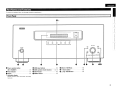
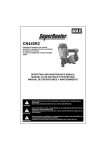
Part Names and Functions
I
For bunons not explained here, see the page indicated in parentheses ( ).
Front Panel
O-CD
DEADAI
[
.. -----
,'1
!©
\'''''''_''._''''''''''''
---
-----
2
3
©
©
...
...
__
__~
_--_
--- ..
©
©i
...... __ ...... __ .........
... __ ........._"J
_ --
4
©
5
,'\
1
o Power operation button
G ZONE select buttons
(ON / STANDBY) ..
... (17)
f) Power indicator·
.
......... (17)
.Display·
.
.. (17)
CD
(10)
o ZONE operation mode indicators
o SETUP button
...
8
DISPLAY button
(6, 13)
(10)
.
o SELECT / ENTER knob ...
oV
(Down) button
4i> /:;. (Up) / RETURN button
.
(10)
(10)
(10)
(17)
Infonnation display
Displays present status information and Setup
menu etc.,
2
ENGLISH
I
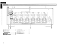
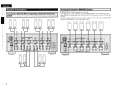
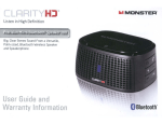
I Rear Panel
4~
4~ 4')
-'---
0
0
4'
,?l
~
'.-J
,""'M$1IIlIJ'I""'"
~O O~ ~.~..~~
••••.I&1!IiiI!lI._.'
1~lrul @1i@~
•
~,lqg~~_J~.. )t. . ._)
________ •
._•••••• _~JIi••••••••• •••••••••IllW'.IUIIL_•••__••
•••••••••IllIlllif.R.IIL._••••••• ••••• _•• .lIll~•• __ •••
••••••••JJIIGGflIJ:
.._.... .........._@............
c..@............ ...........@...........
_.. _.... _.. _...-- ...... _....--- ............
............ _........... _..............
.........._........ _................ ............@....._
_-_ ............. _---_ .........._
_--_... ............@)
---------..... -----------_..... ................@...._
(ej'="O";' 30=0
"............
.~
in
TRlGG£llIi : DC 3-JOV TRIGG£II OIIT: DC 12Y 250mA M l.
~JIi
4 5 O~~O 6
.......... _-_ ... _- ....... __ ....... _-............................
...................
-.. ---------..
.....
BRIDGED
BRIDGED
BRIDGED
0=0~2
0=0
0=0
-------------_.. _.. -_.. __ .. _- ........................ ----_ ........... ..................................... -_ ....'
7
1011
8 9
BRIDGED
BRIDGED
I
BRIDGED
ACIN
....
-Ld
- - i ZONE 1 t---- - - i ZONE 2 t---- - - i ZONE 3 t---- - - i ZONE 4 t---- - - i ZONE 5 t---- --iZONE6t---SPEAX£R SYSTEMS
BRIDGED -
-$
°0
00
00
RS·232C
lIAlGHT CA8lf
... -
-=
0 t~
BRIDGED
2
SPEAX£R SYSTEMS
SPEAXER SYSTEMS
- _........
BRIDGED
BRIDGED
.. _..BRIDGED
_..................
--.. _....+_..- .........BRIDGED
-------- ...................
_---_+ ..
BRIDGED
BRIDGED
BRIDGED
+ _..........
---_BRIDGED
.... _......-_--_ .............
_--------_- ...............
--_ .. --+......
@)o@) @)o@) @)o@) @)o@)
3
4 5
SPEAXER SYSTEMS
SPEAX£R SYSTEMS
6 7
8 9
BRIDGED -
BRIDGED +
··(@)··~·(®)·1
10 11
...
SPEAKER IMPEDANCE NORMAL: 4-16Q
..
4)
.. (9)
•
Speaker tenninals
(SPEAKER SYSTEMS) .
(5)
(10)
(7)
o TRIGGER IN jacks·
8 MASTER TRIGGER OUT jack··
e BUS INPUT connectors···
o BUS OUTPUT connectors····
~ MASTER TRIGGER IN jack
(9)
(9)
(7)
(7)
(9)
0
BRIDGED: 8-16 Q
I
······(8)
~
'
I
RS-232C connector
0
@]
.2
t~. ~. ~. . ...~.~..~.... ...~..~..~ ..~ ~-~... ...~..~..~.... ....@)o@)j
_-------_ ............
•
3
+
(®)'~"(®)'"
1:
o ETHERNET connector·
o AC inlet lAC IN)
o AUDIO INPUT connectors··
SPEAX£R SYSTEMS
I-~
0
ENGLISH
I'Cables Used forConnectiC)ns
Preparations
Select the cables according to the equipment being connected.
Connections
Connections for all compatible audio signal formats are described
in this owner's manual. Please select the types of connections
suited for the equipment you are connecting.
With some types of connections. certain settings must be made
on the POA-3012CI. For details, refer to the instructions for the
respective connection items below.
•
~[.ii.
• Do not plug in the power cord until all connections have been
completed.
• When making connections, also refer to the operating instructions of
the other components.
• In the case of Bus input/output connections, be sure to connect the
left and right channels properly (left with left, right with right).
• Do not bundle power cords together with connection cables. Doing
so can result in humming or noise.
The POA-3012CI incorporates six sets of 2-channel amplifier from
ZONE1 to ZONE6.
The same audio signal can be output from all ZONE or separate
signals can be output from each ZONE. The POA-3012CI also supports
BRIDGED output.
Before making the connections, determine the input signals and
output signals for each ZONE and then set up the POA-3012CI in
accordance with the following procedure.
o
(Black)
Businput/output connections (stereo)
(Black)
S_e_lect
__th_e_in....:p_u_t_te_rm_in::-a_l_to_u_se_.
I
0 9[]::=-----::DlP G
Pin-plug cable
(Black)
Input Setting
c..
Audio input connections
0
0
Stereo pin-plug cable
)
Each Zone input connectors or
. . " . BUS input connectors.
Networic connections
o cmJl.....---~
0
Ethernet cable
Connect the extemal device to the input
terminal.
J
Speaker connections
"'NPlITSElECT" - " ' ' ' ' 131
:
)~iiiiiiiiiiiiiii(
Speaker cables
Set the input source.
)
C~-------=-------::-:--==----
.• Si9n{lldi~ .
"Input Connection" (Gf'page 7)
Select the speaker output method.
I
c..
Output
)
NORMAL output or BRIDGED
. . " . output
I
Audio signal:
~
o Output Setting
(
+
(Input
Input
r
Output
Co_n_n_e_ct~t_h_e_s_p_e_a_ke_r_c_a_b_le_._~-::---)
I
"Speaker Connections"
. . " . (Gf' page 5)
c..
s_e_t_th_e_o_u_tP_u_t-::c-:-h=-a::-:n-=n-=e-:-:I.-:-::=-::--~)
"OPERATION MODE"
(Gf'page 13)
4
ENGLISH
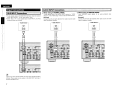
I Co"n~ionMethoct for ~8ID~ED O~ut.
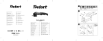
Speaker Connections
Cqnnection; Method When OutPlIttin9
2'Chan"fitl$ Ftom
ZONE,
I o0 on nc
CH 1
=
CH 2
CH 3
CH 4
= =
=
CH 6
CH 5
o0
=
5
=
CH 9
=
CH 10
=
CH 8
CH 7
DO
=
=
CH 11
CH 12
DO
=
=
• In BRIDGED mode, one channel is output from one ZONE.
• To set BRIDGED mode, select "BRIDGED" as the "OPERATION MODE" on the "Main Setup" menu.
• When BRIDGED out putting a signal input to the AUDIO INPUT terminal, input to an even-numbered input
terminal.
• To select a signal for BRIDGED output from among the signals ("t.:' "R:' "L+R") input to the BUS INPUT
terminal, use "INPUT SELECT" on the "Main Setup" menu.
CH1&2
CH3&4
CH5&6
CH7&8
CH9&1O
CHll&12
DDDDDD
ENGLISH
Connecting the Speaker Cables
Carefully check the channel numbers and + (red) and - (black) polarities
on the speakers being connected to the POA·3012CI, and be sure to
interconnect the channels and polarities correctly.
Peel off
ftilO mm ofsheathing
1 either
from the tip of the speaker cable, then
twist the core wire tightly or
about 0.03
terminate it.
Thm the speaker terminal
2 counterclockwise to loosen it.
3 Insert
4
the speaker cable's core wire to
the hilt into the speaker terminal.
Thm the speaker tenninal clockwise to
tighten it.
~.Wh.~J'l u:~ing ~ b~I)~~{t .p'u:g ,t(qfNorttt,~m~~fI)~~lt,~i
Tighten the speaker terminal firmly before
inserting the banana plug.
If speakers with an impedance lower than specified (for example 4
O/ohms speakers/NORMAL MODE) are used for an extended period
of time with the volume turned up high, the temperature may rise,
activating the protection circuit.
There are 2 kind of protection circuits in POA·3012CI.
1. Protection circuit for individual Ampilfier (Zone1 - 6)
This protection circuit detects over load condition of the amplifier
circuit.
When the protection circuit is activiated, the speaker output of
individual Amplifier (Zone 1 - 6) is shut off, and the Zone operation
mode indicator for protected Zone No. flashes red.
If this happen, unplug the power cord, then check the speaker
cable and input cable connections.
2. Temperature rise protection circuit in the chassis
This protection circuit detects temperature rising in the chassis.
When the protection circuit is activiated, the power source for all
Amplifier circuits is shut off, and the power indicator flashes red.
If this happen. it may be extremely hot in the chassis. unplug the
power cord.
Wait for it too cool off and improve ventilation around it.
Once this is done, plug the power cord back in and turn the set's
power back on.
If the protection circuit is activated again even though there are no
problems in the ventilation around the set nor in the connections.
the set may be damaged. Turn the power off. then contact a DENON
service center.
I
-MIn• Use speakers with an impedance of 4 to 16 O/ohms. Use a 8 to 16
O/ohms speaker for BRIDGED output.
• Connect the speaker cables in such a way that they do not stick out
of the speaker terminals. The protection circuit may be activated if
the core wires touch the rear panel or if the + and - sides touch each
other (13f" "Protection circuit").
• Never touch the speaker terminals while the power supply is
connected. Doing so could result in electric shock.
6
ENGLISH
Input Connections
I BUS INPUT ConneCtions "
I
• To play signals input to the BUS INPUT terminal, select the channel
using "INPUT SELECT" on the "Main Setup" menu.
• When "BUS L+R" is used, signals input to BUS INPUT Land Rare
mixed and output as monaural.
Audio Source
o When Using in NORMAL MODE
Input BRIDGED output signals to an even-numbered input
terminal.
[Example)
Connect the left and right channels from audio source to audio
inputs of arbitrary numbers.
[Example)
Connect the left and right channels from audio source to audio
inputs of arbitrary numbers.
Audio Source
AUDIO
0t1T
0t1T
l
00
Signals input from the BUS INPUT are output from the BUS OUTPUT
terminal. These signals can be output to the BUS INPUT terminal of
another POA-3012CI unit.
o When Using in BRIDGED MODE
To play signals input to the AUDIO INPUT terminal, use "INPUT
SELECT" on the "Main Setup" menu to set each channel to AUX.
AUDIO
A
7
IAUDIOINPUT:ConnectioQ~.
l
A
00
Audio Source
AUDIO
0t1T
l
A
00
ENGLISH
Connections to Other Devices
'
Required System
o Broadband Internet Connection
A broadband line connection to the Internet is required in order to
use the POA-3012Cl's firmware update.
~
~,
...
o Modem
Modem
-~
(';:::::::~~--
Internet
(]I
-II
D~
mJ
Router
C
(]I
D
gID
........--~~~
To WAN side
To LAN port
To LAN port
LAN port!
Ethernet
connector
This is a device that is connected to the broadband line to
communicate with the Internet. Some are integrated with the
router
o Router
• When using the POA-3012CI. we recommend you use a router
equipped with the following functions:
. Built-in DHCP (Dynamic Host Configuration Protocol) server
This function automatically assigns IP addresses on the LAN.
. Built-in 100 BASE-TX switch
When connecting multiple devices. we recommend a switching
hub with a speed of 100 Mbps or greater
o Ethemet Cable (CAT-5 or greater recommended)
• The POA-3012CI does not come with an Ethernet cable.
• Some flat type Ethernet cables are easily affected by noise.
We recommend using a normal type cable.
• If the sound is broken in an environment in which there is much
power supply noise from electric products or in a noisy network
environment. use a shielded type Ethernet cable (For North
America modell.
• For the Ethernet cable. used a shielded twisted pair (STP) cable.
Do not use an unshielded twisted pair (UTP) cable. as it may exceed
noise standard limits (For Europe modell.
For connections to the Internet, contact an ISP (Internet Service
Provider) or a computer shop.
-N'U• A contract with an ISP is required to connect to the Internet.
No additional contract is needed if you already have a broadband
connection to the Internet.
• The types of routers that can be used depend on the ISF' Contact an
ISP or a computer shop for details.
o Others
• If you have an Internet provider contract for a line on which network
settings are made manually. make the settings at "Network Setup"
(@"page 15).
• With the POA-3012CI. it is possible to use the DHCP and Auto IP
functions to make the network settings automatically.
• When using a broadband router (DHCP function). the POA-3012CI
sets the IP address. etc,. automatically.
When using the POA-3012CI connected to a network with no DHCP
function. make the settings for the IP address. etc,. at "Network
Setup" (@"page 15l.
• The POA-3012CI is not compatible with PPPoE. A PPPoE-eompatible
router is required if you have a contract for a line of the type with
which the PPPoE is set.
o Computer
A computer with the following specifications is required to use a
server:
·OS
Windows® XP Service Pack2. Windows Vista
• Internet browser
Microsoft Internet Explorer 5.01 or later
• LAN port
8
I
ENGLISH
I Extemal Controller
I
RS.2~2C C()11"ector
This connector is used for an external controller.
* If you wish to control the POA-3012CI from
Master tl'iggerinput jack
The "POWER CONFIGURATION" setting is valid
at the time of a "MASTER TRIGGER ':
Voltage input to the MASTER TRIGGER input
terminal and operating status of the POA-3012CI: t---tt=~~U
At DC 3 - 30 V·········
ON
At DC 0 V··
STANDBY
an external controller using the RS-232C
connector, perform the operation below
beforehand.
G) Turn the POA-3012Cl's power.
® Turn off the POA-3012CI's power from the I--ii'+-~:'i-i
external controller.
QJ Check that the POA-3012CI is in the standby
mode.
The power of an external device equipped with
a trigger input jack can be turned on and off in
association with operations on the POA-3012CI.
• Output level: 250 mA/12 V
Check the trigger input conditions of the
connected device.
• If the trigger input level of the connected device
is higher than 250 mA/12 V and depending on
the short-circuiting conditions. the POA-3012Cl's
protection circuit may be activated, in which
case "TRIGGER OUT OVER LOAD" appears on
the display. If this happens, turn off the POA·
3012CI's power and disconnect the connected
device.
9
The ZONE TRIGGER ON MODE setting is valid at
the time of a "TRIGGER IN':
Voltage input to the TRIGGER IN input terminal
and operating status of the power amplifier of
each ZONE:
At DC 3 - 30V
···········ON
At DC OV
.
····STANDBY
ENGLISH
Using the menu
Connecting the Power Cord
Wait until all connections have been completed before connecting the
power cord.
_.
@"
'0=0
o To select the item to be set
Turn the SELECT/ENTER knob until the item you want to set
appears.
Setup
North America model:
To household power
outlet
(AC 120 V. 60 Hz)
12
o To enable lower level menu items to be displayed
~JRETURN
SETUP
c[ l
l:J
~
------.
@}o~)
I
'@)o~
..
...._-_.. .: : G)
Europe model:
To household power
outlet
(AC 230 V. 50 Hz)
\1
~-I----"'~~
.~[.u.
ZONE1-6
SELECT/ENTER
Insert the AC plugs securely. Incomplete connections could cause
noise.
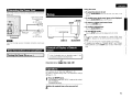
Once Connections are Completed
ITurning the Power On
Example of Display of Default
Values
(rFpage 17)
Press the SELECT/ENTER knob or the \l button.
o To return to higher level menu items
Press the ~IRETURN button.
o To confirm selected item
Press the SELECT/ENTER knob.
o To exit SETUP mode
-
Press the SETUP button until the display returns to normal.
ili".ca··"
If you want to configure the settings for a specific ZONE, press
the ZONE 1 - 6 button for the ZONE concerned and configure the
settings.
• In this case, the setting item of another ZONE is not displayed.
• To configure the settings for "DIMMER MODE" and "POWER
CONFIGURATION:' use the SETUP button to select "Main Setup"
mode.
In lists of selectable items or adjustable ranges, the item
surrounded by a border is the default value.
[Selectable items]
I
I~PQJJt ,;!iID" iP!!t.0~<
Operations
For all settings, refer to "Menu map" (Gf'page 11, 12).
For details of individual settings refer to the explanations of settings
(Gf'page 13 - 16).
1
2
Press the SETUP button.
The POA-3012CI enters the "SETUP" mode and the first level
menu is displayed.
The selected item blinks.
Select the required item on the menu and set it.
10
ENGLISH
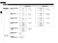
Menu Map
r-- __
p---------------,
~ _~L_;"';_'_'_~ __ .:::~98~M99~":;.:_~,_,,, ;.'-~:;...Jj:~ ~
~_' .. _'..;"":.. _.. _'-M!q§~'_Mql?~ ..;;;__ ~ .. __ .... =_;., __ ~
~
%11---.-------1
(r::rpage 13)
•
.VOLUME CONTROL
(r::r page 13)
------------~-------------~-,
.....................Q:LJ
..................... ~!j ..f
..................... ~!j ..;'!
................Q:P..~.I.~
_ J--__._- BTL O.OdB
........_. qL'1..~.IL _ _
__. ._...qU!._~.I.~ __._.. ._. _
BTL -900dB
J--__._- O.OdB
.
.
-900dB
---.-dB
BTL---.-dB
CH 12 BTL
CH12
f)INPUT SELECT
(r::r page 13)
_______________ (J:L;!..~.I.~_ .._.._.. J---__.__- BTL AUX2
_______________qL'1__~.IL.____________
BTL BUS L
_____________c;:J:i._§._~.IL____________
BTL BUS R
_._.
. ~!j ..J.
._.._. t__-__._- AUX. 1
_____________________CJ:Lf ._. .______
BUS L
____________ ~!j __L_________________
BUS R
BTL BUS L+R
BUS L+R
CH 12
11 LOW CUT FILTER
(r::rpage 13)
CH 12 BTL
_________. ..__ ._.~!j __ L._._.
.....................~!j ..L
_.
..........__
_
Q:t.;'!
l_-__.__- LCF OFF
-
LCF ON
CH 12
BOPERATION MODE
(r::rpage 13)
.................~J:L.] .. ~..f....__._._ t__-__.__.................~.tL;l.~..L.
............_ ~t! ..9..!!!..§ _ .
.................~.t!.J..!!! ..!'! _ .
_.
__ .~.t!_!!._!!!_J.Q
.
(r::r page
14)
_..
.....
~_t:l_.J_.!!! __ f ._.
.__~.t:I..;lA'1._. __._____
NO RMAL
BRIDGED
II DIMMER MODE
(r::rpage
l'
,
I
14)
OFF
Network Setup
Option Setup
DpOWER
CONFIGURATION
11
Bright
Dim
Dark
POWER BUnON
ON LINE
MASTER TRIGGER
-
_._....._._.~.tU..§!.L .._ __ ~--.-L.........._.....~.ti.;lAL .._ _
..............._~.t!.~.~..§ ._._ _
.
~.t! ..?.!!!..!'!
__
.._.._ _.._.Q:UL~.J.Q
_..
CH 11 & 12
J---__.__- CONSTANT
TRIG. IN
A.SIGNAL
OFF
.......__ ~.t! ..9..!!!..§
.__. _.._..~_t!..7..~_.~L __.__
_.__._.._.._. ~_t:l_!!..~.J.Q
__ .
CH 11 & 12
BTL LCF OFF
BTL LCF ON
CH 12 BTL
CH 11 & 12
IIZ0NETRIGGER ON
MODE
---------- (J:iJ-~.I.~--------.----.J---,L...._ _.(J:i..'1..~.IL
_
..._.._.._ (J:i..§_~.I1o_
.
BRIDGED
NORMAL
ENGLISH
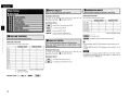
DNetwork.
Information
(Gr'page 15)
DHCP
IP Address
Mac Address
fI Network Setup
DHCP
(Gr'page 15)
•
ON
OFF
~
IPAddress
Subnet Mask
Default Gateway
Primary DNS
Secondary DNS
Proxy
OFF - - -[
ON
Address
Name
- - - - - 1 - Proxy Address
Port
- - - - - 1 - Proxy Name
Port
L
L
D Maintenance
(Gr'page 16)
fI Firmware Update
(Gr'page 16)
12
ENGLISH
.()p.l;~n()NI\IIODE. ... ~
Set$lDeo0tpufrnElthod for channe~ineach lONE. . .
B
fJ
II
D
II
II
II
•
VOLUME CONTROL
INPUT SELECT
LOW CUT FILTER
OPERATION MODE
ZONETRIGGER ON MODE
[Selectable Channels]
[Selectable Channels]
For details of the channels which can be set in each mode, see
[Selectable Channels I in " B VOLUME CONTROL:'.
Sets each of the following channel pairs.
[Selectable items]
CH
CH
CH
CH
CH
CH
.AUX
:AUDIO INPUT terminal of each ZONE.
.8,1tS;!,..
BUSR
: L terminal of BUS INPUT
"
DIMMER MODE
POWER CONFIGURATION
: R terminal of BUS INPUT
NORMAL MODE
BRIDGED MODE
0
0
0
0
0
0
0
0
0
0
0
0
1 &2
3&4
5&6
7 &8
9& 10
11 & 12
, BUU+Il : Land R terminals of BUS INPUT .
~~.';:;:o-:..t:~'~'''.-
Inputs a Land R mixed mono signal.
[Selectable items]
I"~J
,.
Default: NORMAL MODE
:2-channel output
l,!g~iP;; :BRIDGED-channel output (1-channel output)
[Selectable Channels]
Channels which can be set in each mode.
CH
CH
CH
CH
CH
CH
CH
CH
CH
CH
CH
CH
1
2
3
4
5
6
7
8
9
10
11
12
0:
NORMAL MODE
BRIDGED MODE
0
0
0
0
0
0
0
0
0
0
0
0
x
0
x
0
Setting possible
x : Setting not possible
1
13
x
0
x
0
x
0
X
0
Default: NORMAL MODE
[Selectable Channels]
For details of the channels which can be set in each mode, see
[Selectable Channelsl in " B VOLUME CONTROL:'.
[Selectable items]
~~~::; : Low frequency component is cut.
l:ji>QFf,~tl :Low frequency component is not cut.
• During NORMAL MODE, ZONE operations mode indicators are lit
green.
• During BRIDGED MODE, ZONE operations mode indicators are lit
orange.
-N·n.
The method of connecting speakers differs for each mode. Connect
the speakers in accordance with the mode setting. For details, refer to
"Speaker Connection" ((jf'page 5).
ENGLISH
[Selectable Channels]
For details of the channels which can be set in each mode. see
[Selectable Channelsl in "0 OPERATION MODE" (!:'?page 13)
[Selectable items]
;~"':;,!!l!iLi, :Very low display brightness.
1·~g,.§iqJ'J :The power amplifier operates constantly.
~. ::.J!~fusi.,
tli~[li;i;!I!;J;' :The power amplifier operates when trigger input is
II
detected.
When trigger input is not detected, it remains in
standby mode.
•
:Display is off unless controls are operated.
When setting to "Dim': "Dark" and "OFF': the display brightness
changes to "Bright" for about 3 seconds during the operation before
reverting to the set brightness.
ik;~1§!g~:i;,The power amplifier operates when an audio signal is
input.
If no input is received for a period of 10 minutes. it
switches to standby mode.
:'J;J;ii;~!~~:d:JJJl
:Turns the power amplifier off.
The POA-3012CI accepts +3 - 30V trigger input.
~~~~~=
:Operate with the ON/STANDBY button only.
:
rji!;~ii!!kq!I;~lIgii.~'i Operate from an external device via Ethernet
or RS-232C input.
li;.autllllfi~~::1 :Operate by detection of a trigger signal input
.,
to the MASTER TRIGGER input terminal.
• Turns on when a signal is detected.
• If no input is received for a period of 10
minutes, it switches to standby mode.
• The POA-3012CI accepts +3 - 30 V trigger input.
• Even when "ON LINE" or"MASTERTRIGGER" has been set. power
source operation is possible by means of ON/STANDBY button.
14
ENGLISH
'I
·~fittwork '§~p .., .•.
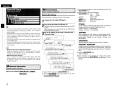
Network Setup
Make network settings.
•
i
Menu tree •
o
•
Mak~settingsfor'~!f~:LAN.
1
Networklnfonnation
~
button:
\l button:
ZONE 6 button :
ZONE 5 button :
Connect the LAN cable (t::V' page 8).
Press
·· Confirm
Cursor to right
Cursor to left
Setting during address entry
Cancel entry
Network Setup
2
..to::
• If you are using a broadband router (DHCP function). there is no need
to make the settings at "Setting the IP Address" and "Setting the
Proxy", since the DHCP function is set to "ON" in the POA-3012CI's
default settings.
• If the POA-3012CI is being used connected to a network without the
DHCP function, the network settings must be made. In this case,
some knowledge of networks is required. For details, consult a
network administrator.
• If you cannot connect to the Internet, recheck the connections and
settings (Gr"page 8)
• If you do not understand about Internet connection, contact your ISP
(Internet Service Provider) or the store from which you purchased
your computer.
3
Tum on the POA-3012CI (t::V'page 17).
df~:
POA-3012CI performs automatic network setup due to the DHCP
function ..
When connecting to a network that has no DHCP function,
perform the setting in step 3.
Set the IP address within the ranges shown below. The Network
function cannot be used if other IP addresses are set.
CLASS A: 10.0.0.0 - 10.255.255.255
CLASS B: 172.16.0.0 - 172.31.255.255
CLASS C: 192.168.0.0 - 192.168.255.255
Set the IP address at the menu "Network Setup" "Network Setup".
r~
Select ·DHCP W •
• DHCP (Dynamic Host Configuration Protocol) :
These are systems by which the IP address and other network
settings are automatically set for the POA-3012CI, computer,
broadband router and network devices.
• DNS (Domain Name System) :
This is a system for converting the domain names used when
browsing Internet sites (for example, .. www.denon.jp .. ) into the
IP addresses actually used for communications (for example,
"202.221.192.106").
1
'. ,
I . _~J~ S'!·!.f;.!_1'L~~t:_ --- - -.
I
.-::. C' t:'
.-::,0=1:"
.') t::' 0=
'~'.l_'_~'.l_''''''''''-'''''''
I
.:"~:-.& • • • • • '• •
'-'_~.
It lit '" .'
.
...
~J
[1
fL~
Sec 0 no::! .::t~-."/
'-.L;,-
L·' !"",!,=.
•
.•
"------;:================-~
P t;'_!-'j§.!-~':~ _ I~i2
:
i1*'
·.
........ ,•
••••
'-;::====::=:=:===========~
a Network ,Infonnation
'1-
[Ti;~:r.;~:~:::~~:::}:}. d.. •••• .. ••••• .. :
~£1.
4)._:
··:.
..... 4f
DisplaY ~etwork .Information.' ,,'
[Items to be checked]
When connected to a gateway (router), input its IP address.
M
Addre~~
I
h.PttCP. ON or Off.. .., Address
® Input the addres;.
CD Select" DHCP" and press the SELECTJENTER knob.
,tfA~6!!!tel
@ Turn the SELECT/ENTER knob to set "DHCP" to "OFF", then
:'~<<>:i,
,'''''''''''~;:'': -!h:,;;-_"~':~':'U':;,};_
Wj(L~~;~
press the SELECTJENTERknob.
The DHCP function is disabled.
i~.~~:
When connecting an xDSL modem or terminal adapter directly
to the POA·3012CI, input the subnet mask indicated in the
documentation supplied by. your provider. Normally input
255.255.255.0.
!,~.~~~,;.
,I :;1{:'~lt
_ _ _ _ _ _'--_-_~_.-:.:-:-·:~~.:.:I'=@=2=Se=t=·Q=F=F=.
IP
15
* SELECTJENTER
Button functions when entering address
knob: Turn
Select
Use this procedure to configure the Wired LAN settings.
Network Setup
the following buttons to input the address and press the
SELECT/ENTER knob.
Wired LAN settings
Main Setup
It:,
® Use
t~~PN$,.~~DNS
If there is only one DNS address indicated in the documentation
supplied by your provider, input it at "Primary DNS". If there are
two or more DNS addresses, input the first one at "Secondary
DNS".
® Press the SELECT/ENTER knob.
Setup is complete.
* When
connecting to the network via a Proxy server, select
"Proxy" and press the SELECT/ENTER knob (Gr"page 16 "Proxy
settings") .
ENGLISH
o
Proxy settings
Make this setting when connecting to the Internet via a proxy server.
:+: t·~
CD
e 1:: i.•J 0
~-.
I•• ""-...:~",:",j:,-=:,-=,;-",~-"":-,,,::-,,,:-,,-:-,-}
Select MProxy·.
® Selecting the
input method
Example) Address
.c::
k
Set U F-
@ Use the following buttons to input the proxy server address or
domain name and press the SELfCT/ENTER knob.
'* SELfCT/ENTER
-----'
* F' ,-. ,-, ',., .....
~r------------.
~ _.Iid,~ ~-.;..;:;;:.=: _ ~
@ Input the
Update Check
You can check for firmware updates. You can also check approximately
how long it will take to complete an update.
Update Start
the SELfCT/ENTER knob to select the "Port" and press
SELfCT/ENTER knob.
®
Execute the update process.
When updating starts, the power indicator lights red. "Updating
is shown on the display during updating. Once updating is
completed, "Updatingcomplete" is displayed.
"Latest firmware" is displayed when the firmware is the latest
version.
** *"
® Turn
address
or domain
name.
II fjl1Jlware Update
UPdate the'firmware of the multi channel power amplifier.
Button functions when entering address
knob: Turn .. ·
·Select
Press · ·.. ··Confirm
~ button:
Cursor to right
\l button:
Cursor to left
ZONE 6 button:
Setting during address entry
ZONE 5 button:
Cancel entry
DISPLAY button:
Character insert/delete/overwrite
Cursor ~: Character insert
Cursor ~: delete
Cursor.: overwrite
When "Address" is selected in step ®: Input the address
When "Name" is selected in step ®: Input the domain name
Use the above buttons to input the proxy server port number and
press the SELfCT/ENTER knob.
'*' If the display reads as shown below, check the settings and network
environment, then update again.
(J) Press the SELfCT/ENTER knob.
)j:
Setup is complete.
I- •
=--=~~"="='-a--------'
number.
Select menu "Network Setup" - "Network Setup" - "Proxy" and
press the SELfCT/ENTER knob.
<1> Turn the SELfCT/ENTER knob to set "Proxy" to "ON" and press
the SELfCT/ENTER knob.
The proxy server is enabled.
® Turn
the SELfCT/ENTER knob to select the proxy server input
method. and then press the \l button.
[Selectable items]
AddrllSS : Select when inputting by address.
Name
: Select when inputting by domain name.
<>:,:".J,;=~~"""
[Characters that can be input]
a ~~
"';::}:i,:f..,>;:,>!,<
.0< . . .:
<,
':'Q~lrti9"
;t
Updating failed
Updating failed.
Login failed
Failure to log into server.
Server is busy
Server is busy. Wait a while then try again.
Connection fail
Failure connecting to server.
.~(.ji.
® Input the port
CD
kt
O~9;
.·~;::,':'!.·Jl· tt':JJ.i.:'fi:1 ~ nJl~.a.s.e).
.M,intenan~L '.
Thj!) ;,5ets:' the function for maint~nance by' a DENQN
'. s~ivic~~rson'or instalter~ (For professJorjal use only.) ,
.
This function allows a DENON serviceperson or installer to check the
POA-3012CI's status and make settings via the Internet.
'N'O*
Only use this function if so instructed by a DENON serviceperson or
installer.
• Connection to the network and specific settings are required to
update the firmware. For details, see page 8, 15.
• Do not turn off the power until updating is completed.
• Normally there is no need to use this function, aside from the cases
described below.
, The Firmware Update function is only used for updating the
firmware (free or for a charge) via the Internet, for example for the
purpose of adding functions to the POA·3012CI in the future.
· Information regarding the Firmware Update function will be
announced on the DENON web site each time related plans are
defined.
· A broadband connection to the Internet is required to use this
function (rF' page 8).
· Even with a broadband connection to the Internet, approximately
13 min is required for the updating procedure to be completed.
Once updating starts, normal operations on the POA-3012CI cannot
be performed until updating is completed.
Furthermore, updating the firmware may reset the backup data for
the parameters, etc., set for the POA-3012CI.
16
•
ENGLISH
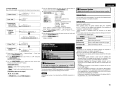
Check the Status of Each Channel
1
Operation
ZONE
op,,,tioo mod, iOdi"'tO'~'~~SELECTIENTER
*
*
DISPLAY button.
. -,-:-
Zone status is indicated on the bottom line of the display.
Turn the SELECTjENTER knob to change the display as follows.
Channel No. & INPUT Line - - VOLUME CONTROL lellel
[
-
...
Press the
.. ZONET.ON MODE - - LON CUT FILTER
.OPClr:atin9 .th~. POA~3012CI .Using
BroW$M (Web'f;Ontroll
I
,'•.' ,; - .,-, .'.'
.
. ..~.,. '-~,-_:",</,_.
a
- ,..:
This.function lets YolJ~ratethe Pq..\-3P12CI using Internet
Exp.lorer!>Y",. ." g ......;.y;·Y.c Y;,.:..,'
,... 'y;":'.' <.•. .'
.
.
1
-----J
Check the POA-3012CI's IP Address.
-Network SetupW - -Network Infonnation- (Grpage 15)
-,;~~
..-_:..!J
I o~I~-DT""B-y----z-J-E-5-D-I-J: )1
.6./RETURN
ON/STANDBY button.
The power indicator flashes green and the power turns on.
* The
signal input to each channel is output from the speaker
terminal of each channel.
* The setting status of each channel is indicated on the display.
* Turn the SELECT/ENTER
knob to change the channel displayed.
Output channel
Input terminal
I
i
i
Press the DISPLAY button again.
* System status is indicated on the bottom line of the display.
* Turn the SElfCT/ENTER knob to change the display as follows.
POWER CONFIG - - DIMMER
2
Input the POA-3012CI's IP Address in Internet
Explorer.
For
example.
if the IP address is "10.3.18.90; enter
http://10.3.18.90.
3
H the top menu is displayed, click ''Setup Menu"•
4
When the ''Setup Menu" is displayed, click on the
menu you want to operate.
o To Retum to the Regular Display
Press the .6./RETURN button until the display returns to normal.
Turning the Power On
Press the
2
I
rO:' .-:
I~·:L
OPERATION MODE
Volume level
(No display when in "NORMAL MODE")
o To return to STANDBY
Press the ON/STANDBY button again.
The power indicator lights red.
Other Operations
o To Adjust the Volume
Refer to "VOLUME CONTROL.:' on the "Main Setup" menu
(Grpage 13)
o To Switch Input Setting
Refer to "INPUT SELECT" on the "Main Setup" menu (Grpage
13).
o To Reduce the Low Frequency Volume
Refer to "LOW CUT FILTER" on the "Main Setup" menu (Grpage
13).
-------Click the menu
CHANNEL SETUP IGrExample: 1)
SYSTEM SETUP IGrExample : 2)
WARNING AND PROTECTION DATA
IGrExample : 3)
AUDIO SIGNAL AND TRIGGER
INPUT IGrExample : 4)
OPTION SETUP IGrExample: 5)
ll
-k
".
-When
the
"POWER CONFIGURATION" is set to "MASTER
TRIGGER': the device will automatically enter the standby status
when no trigger input is detected for a period of 10 minutes.
- When the "POWER CONFIGURATION" is set to "ON LINE': send
a standby command to the ETHERNET terminal or the RS-232C
terminal of the POA-3012CI.
- Power continues to be supplied to some of the circuitry even when
the power is in the standby mode. When leaving home for long
periods of time or when traveling, unplug the power cord from the
power outlet.
17
Click -SAVE- when you want to save settings,
and click -LOAD- when you want to call settings
Becomes each operation screen
ENGLISH
5
Operate.
(Example: 3] Warning and Protection Data Screen
To use the web control function. set the menu "Main Setup"- "POWER
CONFIGURATION" - "ON LINE" ((Fpage 14).
(Example: 1] Channel Setup Screen
'~[.jj.
• To perform web control. you must connect a web control device
such as a PC to the same network as the POA-30 12CI.
• With web control. some network settings. etc., cannot be set.
• When updating firmware. settings made by the web controller may
be reset.
Re§ettingthe~icroproce"()r
(Example: 4] Audio Signal and Trigger Input Screen
.
PerfQrmthis procedl.lI'e jf the' qisplCiyisabnormal:or.jf
oper~tions cannot tJep~rforme(L '
' •.
',;\
VYn~e.lh~ h;lic roprocE!ss is; [e~et.,~II.t6e,settiOQs.;arEl
9[
"reseHgthekclefCl\.lltvaJues ,:\,' . : , '
Enter figures or click u< U or u>u to make
the setting. and then click USet~
* :Normally. there is a change to the latest information each time
you operate. When operated from the main unit, click because the
screen is not updated.
(Example: 2] System Setup Screen
(Example: 5] Option Setup Screen
. . .
1
Unplug the power cord from the power outlet.
2
Connect the power cord to the power outlet while
simultaneously pressing the ZONE 5 and DISPLAY
buttons.
3
When all Zone operation mode indicators are
illuminated in red and " *EEPROM INIT. *.. is
displayed. release finger from two buttons.
If in step 3 the could not be start over from step 1.
18
I
ENGLISH
Troubleshooting
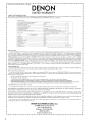
Specifications
Check the following before assuming there is a problem with the set:
1. Are all connections proper?
2. Is the set being operated as described in the owner's manual?
3. Are the speakers and input components being operated proper1y?
Rated output:
If the set does not seem to be operating properly, check the points listed below. If these points do not
apply, the set may be damaged. Turn off the power immediately and contact your store of purchase.
Symptom
...•..
". Cause
When the power is • The power supply cord's plug is • Make sure the unit is correctly
turned on, the power
plugged in and switched on at
not fully plugged in.
indicator does not
the mains socket.
light and no sound
is produced.
10
The power indicator • The speaker cables are not fully • Connect securely.
lights but no sound
connected.
is produced.
• The device you want to listen to • Insure the correct input is
has not been selected.
selected.
• The volume control is set to • Set to an appropriate level.
minimum.
• The input cable is not fully • Connect securely.
connected.
the
speaker
as
• The speaker cable is not. Connect
connected properly for the
required for the Operation Mode
operation mode.
(NORMAL MODE or BRIDGED
MODE)
• The input connector is not • Connect the input connector
connected properly.
correctly (in the case of BRIDGED
input for each ZONE, input to an
even-numbered channel.)
• The "Turn On" command is not • Send the "Turn On" command
input from the external terminal
from the external device.
when the ZONE TRIGGER ON
MODE is set to ON LINE (the
ZONE operation mode indicator
is not lit).
• Trigger voltage is not input to • Input the trigger voltage from
the TRIGGER IN terminal from
the external device.
the external device when the
ZONE TRIGGER ON MODE is
set to "TRIG. IN':
5
19
Total harmonic distortion:
Output terminals:
Input sensitivity I Input impedance:
Gain:
7
17
Frequency response:
SIN raito:
Low cut filter:
Trigger in level:
Trigger out level:
Power Supply:
Power Consumption:
7
5
Maximum external dimension:
Weight:
12-channel driving, NORMAL operation:
30 W x 12 ch (8 (lJohms, DIN 1 kHz with 0.7 % TH.D.)
50W x 12 ch (4 (lJohms, DIN 1 kHz with 0.7 % TH.D.)
6-channel driving, BRIDGED operation:
100W x 6 ch (8 (lJohms, DIN 1 kHz with 0.7 % TH.D.I
0.05% (Rated output: -3 dB, 8 (lJohms, 1 kHz)
Speaker 4 - 16 (lJohms (NORMAL operation)
Speaker 8 - 16 (lJohms (BRIDGED operation I
550 mV /47 k(lJkohms (NORMAL operation)
275 mV /47 k(lJkohms (BRIDGED operationl
29 dB (NORMAL operation)
35 dB (BRIDGED operation)
5 Hz - 40 kHz (Low cut filter: OFF)
95 dB (input terminals short-circuited, with A-weightied network)
Cut off freguency 80 Hz (-12 dB/oct. Low cut filter: ON)
3-30VDC
12 V DC, 250 mA MAX
AC 120 V, 60 Hz (North America model) / AC 230 V. 50Hz (Europe model)
2.5 A (North America model) /230 W (Europe model)
Standby: 0.5 W or less
(When the "POWER CONFIGURATION" is set to "POWER BUTTON")
434 (W) x 171 (H) x 410 (D) mm (17-3/32" x 6-47/64" x 16-9/64")
19.0 kg (Approx 41 Ibs 14.2 oz)
* For purposes of improvement, specifications and design are subject to change without notice.
7
9, 14
9, 14
20
DENON
www.denon.com
Oenon Brand Company, O&M Holdings Inc.
Printed in Japan 000511 4719004
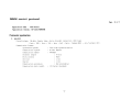
DENON control protocol
Ver. 5.1. 7
Application model :
POA-3012CI
Application terminal: RS-232C/ Ethernet
Connector specification
I. RS-232C
Connector type:
DB-9pin female type, slave straight connection (DCE type)
( 1pin : GND, 2pin : TxD , 3pin : RxD , Spin: Common (GND) , 4,6,7,8,9pin
Communication format:
Synchronous system
Tone step synchronization
Communication system
A half duplex
Communication speed
9600bps
Character length
8 bits
Parity control
None
Start bit
1 bit
Stop bit
1 bit
Communication procedure
Non procedural
Communication data length
135 bytes (maximum)
- 1-
NC)
n.
Ethernet
Connector type
Example
RJ-45 (lOBASE-T!lOOBASE-TX)
CD
PC
Ethernet
Cross cable
h
r
POA-30l2CI
L
I--J
Example (2)
POA-30l2CI
PC
Ethernet
Straight
cable
Communication format
Communication
Communication
Communication
Communication
system
speed
port
data length
Ethernet
Straight
cable
A half duplex
lOMbps!lOOMbps
TCP port 23 (telnet)
l35bytes (maximum)
-2 -
NE'IWORK SETUP of POA-3012CI
>Procedure of Network Setup mode.
(1) Press MENU button and select "system set up" with rotary encoder, then System Setup Menu appears on FL-display.
(2)Select "Network Setup> Detail" .
(3)Set parameters described below.
<DHCP>
"ON"---Use this setting when DHCP server is on the local network.
"OFF"---Use this setting when DHCP server is not on the local network.
<IP Address> When <DHCP> sets "OFF", please set IP address.
When <DHCP> sets "ON", you can confirm the IP address that is set by server.
<Subnet Mask> When <DHCP> sets "OFF", please set Subnet Mask.
When <DHCP> sets "ON", you can confirm the Subnet Mask that is set by server.
<Gateway>
Set the address of Gateway when Gateway is on the local network.
Do not set this parameter when Gateway is not on the local network.
<Primary DNS> Do not set this parameter.
<Second DNS> Do not set this parameter.
<Proxy>
Set this parameter "OFF".
<Network Option: Standby Mode Power Saving>
(1) Press MENU button and select "power configuration", then Menu appears on FL-display.
(2)Set parameters described below.
"ON LINE"---Use this setting when using the POA-3012CI connected in a network.
"MASTER TRIGGER" or "POWER BUTTON"--- Use this setting when not using the POA-3012CI connected in a network.
This setting is reducing the power consumption in the standby mode.
-3-
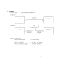
Protocol specification
The following three data forms are defined.
Ca.MAND
The message sent to a system(POA-3012CI) from a controller(Touch Panel etc.)
A command to a system is given from a controller.
EVENT
The message sent to a controller (Touch Panel etc.) from a system (POA-3012CI)
The result is sent, when a system is operated directly and a state changes.
*The form of EVENT presupposes that it is the same as that of ~ .
**Refer to the following table for the contents of ~ and EVENT.
RESPONSE
The message sent to a controller (Touch Panel etc.) from a system (POA-3012CI)
if the 'request command' (~?+CR(OxOD)) has came from a controller.
The RESPONSE should be sent within 200ms of receiving the ~ .
*The form of RESPONSE presupposes that it is the same as that of EVENT.
Basic specification: The command by ASCII CODE, parameter expression
*ASCII CODE which can be used is from Ox20 to Ox7F: the alphabet and the number of 0-9, and space (Ox20), some signs,
AND carriage return (OxOD) --- I t is used only as a pause sign.
Command structure: COMMAND + CHANNEL + PARAMETER + CR (OxOD)
COMMAND: ASCII CODE of 2 characters
Ex.
SI
Select Input source
SV
Volume setting
SO
Operation mode Setting
SF
Low cut filter Mode Setting
PW
system Power setting
CHANNEL
ASCII CODE of 2 characters (00 to 12)
channel number
Ex.
09
for system setting
00
PARAMETER : ASCII CODE ( up to 25 characters)
Ex.
BUSL : function name
BRIDGED: operation mode name
*Special Parameter--- ? : for request command
The example of a
c~d
* <CR> is the meaning of OxOD.
SI09BUSL<CR>
Select Input source "BUS L" at channel 9.
S006BRIDGED<CR>
Set Operation Mode to bridged mode at channel 5 & 6.
SV02UP<CR>
Master Volume UP at channel 2.
PWOOON<CR>
system PoWer ON
PWOOSTANDBY<CR>
system PoWer STANDBY
SI04?<CR> : Request command for now playing input source at channel 4 » Return RESPONSE 'SI04****<CR>'
-5.
Others
A) COMMAND is receivable also during transmission of EVENT.
B) The RESPONSE should be sent as opposed to the request command by all the commands with which an EVENT exists , not need to
the another request commands (ex. SV command).
C) The PARAME'lER (with ~ and RESPONSE, EVENT) of minimum level of MASTER VOLUME defines "99".
0)
K)
If the MASTER VOLUME & CHANNEL VOLUME set with O.5dB step, the P ~ (with ~ and RESPONSE, EVENT) defines three
ASCII characters as bellows.
Ex.
MASTER VOLUME = OdS
SV90<CR>
-O.5dB
SV895<CR>
-1. OdB
SV89<CR>
I
I
SV005<CR>
-89.5dB
-90.0dB
SVOO<CR>
---.-dB
SV99<CR>
* At the **.OdB step, only uses two ASCII characters as PARAME'lER, same as usual.
Four seconds later, please transmit the next ~ after transmitting a power on ~ (PWOOON)
- 6-
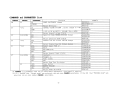
COMMAND and PARAMETER list
PARAME7ER
function
example
ON
POWER ON/STANDBY change
PWOOON<CR>
STANDBY
PWOOSTANDBY<CR>
?
Return PW Status
PWOO?<CR>
SV
*01-12
UP
CHANNEL VOLUME UP/DOWN , direct change to **dB SVOlUP<CR>
DOWN
SV01DOWN<CR>
**
**:00 to 99 by ASCII , 90=OdB, 99=---(MIN)
SV0180<CR>
?
Return channel volume Status
SV01?<CR>
SO
02-12 (EVEN)
NOR
Operation mode NORMAL/BRIDGED change
S002NOR<CR>
BRI
S002BRI<CR>
?
Return operation mode status
S002?<CR>
*01-12
SF
OFF
Channel Low Cut Filter OFF/ON change
SFOSOFF<CR>
ON
SFOSON<CR>
?
Return channel Low Cut Filter status
SFOS?<CR>
SI
*01-12
BUSL
Select input "BUS L"
SI06BUSL<CR>
BUSR
BUS R
SI06BUSR<CR>
BUSM
BUS MONO (L+R)
SI06BUSM<CR>
AUX
AUX
SI06AUX<CR>
?
Return channel Input status
SI06?<CR>
ST
02-12 (EVEN)
CONT
constant
ST08CONT<CR>
TRIG
Trigger in
ST08TRIG<CR>
ASIG
Audio signal
ST08ASIG<CR>
OFF
Off
ST080FF<CR>
?
Return Zone Turn On status
ST08?<CR>
PBTN
00
Power button
STOOPBTN<CR>
TRIG
MASTER TRIGGER
STOOTRIG<CR>
ONLI
ON LINE
STOOONLI<CR>
?
Return Power ON status
STOO?<CR>
SV CGHAND : "*" parameter uses two or three ASCII characters. (see page6 D) section)
*01-12 : The ZONE that "Normal mode" was selected, odd and even CHANNEL selectable. I f the ZONE that "BRIDGED mode" was
selected, only an even number CHANNEL selectable.
CGHAND
PW
CHANNEL
00
-7-
CHANNEL
so
00
function
p~
i-=-B.:. R;.::I
--l.. F~_9~:SE~~~9_immeE_.~.:=yel:_c::~~rl.9~
1DIM
---------+
DAR
OFF
TI
AI
PR
02-12 (EVEN)
00
02-12 (EVEN)
00
02-12 (EVEN)
?
?
?
?
TR?
IN?
TM?
PR?
OH?
Return
Return
Return
Return
Return
Return
Return
Return
Return
example
_.. I--S_D_O_O_B_R_I_<_C_R_>
-I
SDOODIM<CR>
1--------------------1
SDOODAR<CR>
SDOOOFF<CR>
dimmer status
SDOO?<CR>
channel trigger input
TIl2?<CR>
TIOO?<CR>
master trigger inputs
channel audio signal input
AI02?<CR>
system(Main transformer) over heat data PROOTR?<CR>
system(Cabinet inside) over heat data
PROOIN?<CR>
system total operation time
PROOTM?<CR>
PR10PR?<CR>
channel protection data
channel over heat data
PR100H?<CR>
-8 -
_.__ _
EVENT(or RESPONSE) and PARAMETER list
EVENT
CHANNEL
PW
00
SV
*01-12
SO
02-12 (EVEN)
SF
*01-12
SI
*01-12
ST
02-12 (EVEN)
00
.., ....-
... _.._._._.. _._ ..._.
SO
TI
__.
00
00
00
00
02-12 (EVEN)
00
AI
02-12 (EVEN)
NOR
BRI
OFF
ON
BUSL
BUSR
BUSM
AUX
CONT
TRIG
ASIG
OFF
PBTN
TRIG
ONLI
BRI
DIM
DAR
OFF
YES
NO
YES
NO
YES
NO
example
function
PARAMETER
ON
STANDBY
**
POWER ON/STANDBY
CHANNEL VOLUME change
90
00
99
OPERATION
, **:00 to 99
by ASCII
= OdB(MAX)
= -90dB
= ---(MIN)
MODE change
Channel Low Cut Filter OFF/ON change
Channel INPUT source change
Zone turn on mode change
Power configuration change
_ _ _....-........._..__... _ ..-._--_ ..._._._-_. __.._-._._--_.._._-----_..
.. ....... ....
Dimmer level change
Zone trigger input YES/NO change
.t>1Cl~~.eE~E~99~E . . . ~I1Pll~ .X~~/~(?<::~ClI19~
channel audio signal input YES/NO change
·9·
PWON<CR>
PWSTANDBY<CR>
SV80<CR>
S002NOR<CR>
S002BRI<CR>
SF040FF<CR>
SF040N<CR>
SI03BUSL<CR>
SI03BUSR<CR>
SI03BUSM<CR>
SI03AUX<CR>
ST06CONT<CR>
ST06TRIG<CR>
ST06ASIG<CR>
ST060FF<CR>
STOOPBTN<CR>
STOOTRIG<CR>
STOOONLI<CR>
SDOOBRI<CR>
SDOODIM<CR>
SDOODAR<CR>
SDOOOFF<CR>
TIl2YES<CR>
TI12NO<CR>
TIOOYES<CR>
TIOONO<CR>
AI02YES<CR>
AI02NO<CR>
EVENT
PR
CHANNEL
00
PARAMETER.
TROHWARN
TROHNONE
INOHWARN
I NOHNONE
TMOHTR01******
TMOHTR02******
I
TMOHTR20******
TMOHIN01******
TMOHIN02******
I
TMOHIN20******
TM******
02-12 (EVEN)
PRWARN
PRNONE
OHWARN
OHNONE
PR******
OH01******
OH02******
I
OH20******
function
MAIN TRANSFORMER OVER HEAT WARNING
MAIN TRANSFORMER OVER HEAT NONE
CABINET INSIDE OVER HEAT WARNING
CABINET INSIDE OVER HEAT NONE
MAIN TRANSFORMER
Over heat operation time (latest)
Over heat operation time (latest 1st ago)
I
Over heat operation time (latest 19 th ago)
******:000000 to 999999 by ASCII
, 000230 = 2hour30min
CABINET INSIDE
Over heat operation time (latest)
Over heat operation time (latest 1st ago)
I
Over heat operation time (latest 19 th ago)
******:000000 to 999999 by ASCII
, 000230 = 2hour30min
Total operation time
******:000000 to 999999 by ASCII
, 001120 = 11hour20min
ZONE POWER MODULE PROTECTION WARNING
ZONE POWER MODULE PROTECTION NONE
ZONE POWER MODULE OVER HEAT WARNING
ZONE POWER MODULE OVER HEAT NONE
Protection operation time
******:000000 to 999999 by ASCII
, 000230 = 2hour30min
Over heat operation time (latest)
Over heat operation time (latest 1st ago)
I
Over heat operation time (latest 19 th ago)
******:000000 to 999999 by ASCII
, 000230 = 2hour30min
- 10 -
example
PROOTROHWARN<CR>
PROOTROHNONE<CR>
PRO 0I NOHWARN<CR>
PROOINOHNONE<CR>
PROOTMOHTR01000130<CR>
PROOTMOHTR02000140<CR>
I
PROOTMOHTR20000230<CR>
PROOTMOHIN01000130<CR>
PROOTMOHIN02000140<CR>
I
PROOTMOHIN20000230<CR>
PROOTMOO1120<CR>
PR08PRWARN<CR>
PRO 8PRNONE<CR>
PR080HWARN<CR>
PR080HNONE<CR>
PR04PROOO130<CR>
PR040H01000130<CR>
PR040H02000140<CR>
I
PR040H20000230<CR>
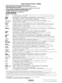
DENON SERVICE NETWORK I ij~~~~
Please consult the outlet where the equipment was purchased.
Bitte wenden Sie sich an den Handler, bei dem Sie das Produkt gekauft haben.
SVP veuillez consulter votre revendeur.
Neemt u alstublieft contact op met het verkooppuntwaar u de apparatuur heeft gekocht.
Por favor consulte en el establecimiento donde compr6 el equipo.
Vanligen ta kontakt med butiken dar du kopt utrustningen.
Rivolgetevi al rivenditore che vi ha venduto I'apparecchio.
Contacte a loja onde comprou 0 equipamento.
• ~.rDJf,jllUl.A*lIlr-Jifij~1i:~ 0
• iRfDJfmJiJi~~*~Ur-Jifljlr~~ 0
Australia
Audio Products Group Pty Ltd. 67 O'Riordan Street Alexandria NSW 2015. PO Box 150, Mascot NSW 1460 Australia
Tel: 1300134400 Fax: +61 295780159
Austria
Digital-Professional-Audio Vertriebsges.m.b.H., Seebockgasse 59, A-1160 Wien Tel: 01-480-1006 Fax: 01-485-7679
Belgium
Transtel-Sabima PVB.A. Duboisstraat48, B-2060 Antwerpen, Belgium Tel: 03-237-3607
D&M CANADA INC. 5-505 Apple Creek Blvd., Markham, Ontario, L3R 5Bl Tel: 905-475-4085 Fax: 905-475-4159
Canada
!tJ.{f~~!fl(uJm ~(J:~ HHN0P.1 J:IIlHIJiIt!8epJ*887 f hj(i,li::kJ5i:6010£
China
!tJ.i;s:(Q21 )64372299 fHU021 )64339973 Bl~!!1il: 200020 7<:;it~F~IHHM~: 021-62949285
EUROSTAR OSTRAVA s.r.o. areal Vodni stavby Praha, budova A2 Dobronicka 635,14800 Praha 4 Czech Rep
Czech republic
Tel: 261-112-901 Fax: 261-112-904
Denmark
Hifi Klubben A/S Dali Aile 1, 9610 Noerager, Denmark Tel: 45-96 72 1000 Fax: 45-96 72 10 14
Soundata Oy Hameentie 157 5th floor 00560 Helsinki Finland Tel: +358-(0)9-47693300 Fax: +358-(0)9-47693310
Finland
France
DENON FRANCE A division of D&M France SAS Tour Ventose, 2 rue des Bourets, 92156 Suresnes Cede x, FranCE;
Tel:+33(0)1-41-383230 Fax +33(011-41-380110
Germany
DENON DEUTSCHLAND A division of D&M Germany GmbH An der Landwehr 19, D-41334 Nettetal, Germany
Tel: +49(0)2157-1208-0 Fax: +49(0)2157-1208-15
KINOTECHNIKI LTD. 14, PYRGOU STR 16675, GLYFADA ATHENS Tel: +30210 9601071 Fax: +302109601072
Greece
Hong Kong
D&M Sales and Marketing (HK.) Ltd. Unit 501, Ocean Centre, Harbour City, 5 Canton Road, Tsimshatsui, Kowloon, Hong Kong
Tel: 852-2516-5864 Fax: 852-2516-5940
=i!l'~jLiI~;J.2t:J;D.fl.lJnf!it!55JJt1Jjj~lJjX$j'(oep,L'5.m1501 ~ ~gi5: 852-2516-5864 {$J'j:: 852-2516-5940
Hungary
A.I:D.A. Audio Kft. 1112 Budapest Olt u. 37 Hungary Tel: 01-248-2030 Fax: 01-248-2039
Einar Farestveit & co hf. Borgartun 28, PBox 5440, 125 Reykjavik. Tel: +3545207900 Fax: +3545207910
Iceland
India
PROFX SERVICE CENTRE Advanced Audio Solutions (Bangalore)Pvt. Ltd.
No 53, K.H.Road, Opp .Big Bazaar, Bangalore - 560 027, India Tel: 080 3297 0853 Fax: 080 2211 2043
Indonesia
PT Autoaccindo Jaya. Cideng Barat NO.7 Jakarta, Indonesia Tel: +62-21-633-2730 Fax: +62-21-632-2886
Israel
Newpan Ltd. 14 Rosansky st. Rishon Lezion 75706, Israel: Tel: +972-3-953-5900 Fax: +972-3-961-6193
Audiodelta S.r.1: 19 Via Pietro Calvi 20129 Milano Italy Tel: 39-02-5411-6008/39-02-5412-8253 Fax: 39-02-5412-0258
Italy
Korea
D&M Sales and Marketing Korea Ltd. Chung Jin B/D., 10F, 53-5, Wonhyoro 3 Ga, Yongsan-Gu, Seoul, 140-719, Korea
Tel: 02-715-9041 Fax: 02-715-9040
Malaysia
Wo Kee Hong Trading Sdn Bhd. 2nd Floor, (Left Wing), Bangunan Infinite Centre, Lot 1, Jalan 13/6, 46200 Petaling Jaya,
Selangor Darul Ehsan, Malaysia Tel: 03-7954-8088 Fax: 03-7954-7088
Labrador, SA de CV Callejon del Naranjo 35, Naucalpan, 53560, Edo. Mex., Mexico Tel: 52-5359-5161 Fax: 52-5357-1775
Mexico
Penhold BV Poppenbouwing 58, NL-4191 NZ Geldermalsen, Netherland Tel: 31-345-588080 Fax: 31-345-588085
Netherlands
New Zealand
Avalon-Pacific Marketing Limited. 15C Vestey Drive, Mt Wellington, Auckland, New Zealand.
PO Box 11 631 Ellerslie, Auckland, New Zealand Tel: +64-9-573-5933 Fax: +64-9-573-3720
Norway
Hi-Fi Klubben Marcus Thranes gate 4-6, 0473 Oslo, Norway Tel: +47228063 10 Fax: +4722 80 63 29
Philippines
Lotteworld Audio Video Systems Incorporated CET Building Mezzannine Floor No.4 Mindanao Avenue, Barangay
Bahay Toro, Project 8, Quezon City, Philippines. Tel: +632-929-5334 Fax: +632-929-1343
Poland
HORN DISTRIBUTION SA Ulica Kurantow 34,02-873 Warszawa Poland Tel: +4822331 5533 Fax: +4822331 5500
Videoacustica Qta. Do Paizinho-Armazem 5-Estrada De Circunvalac;:ao-Apart. 3127 1303 Lisboa Codex
Portugal
Tel +351 214241770 Fax: +351214188093
Singapore
ALL (E&E) Service Center Pte Ltd. Machtech Industrial Building, #06-04, No.2, Kallang Pudding Road, Singapore 349307
Tel: 6747-8274 Fax: 6748-9007
Slovakia
BIS AUDIO s.r.o. Dobronivska cesta 1642/696001 Zvolen Tel:045-5400 703 Fax:045-5400 704
South Africa
Mandarin Distributors SA 10 Thora Crescent, Wynberg Ext.3 Sandton, P.O.Box 5137, Johannesburg Republic of South
Africa Tel: 27-11-444-8445 Fax: 27-11-444-8363
Spain
Gaplasa S.A.AV. Ing. Conde de Torroja, 25, 28022 Madrid Tel: 91-746-00-45 Fax: 91-329-44-57
Hi-Fi Klubben Goteborg Skanegatan 25, 41252 Goteborg Tel:031 3351010 Fax:031 3351019
Sweden
Switzerland
DKB household AG, Abteilung Elektronik. Eggbuhlstrasse 28, CH-8052 Zurich, Switzerland
Tel 01-306-1626 Fax: 01-306-1690
Taiwan R.O.C.
D&M Sales and Marketing Taiwan Ltd. 6F-2 N0148, Songjiang Rd., Taipei City 10458, Taiwan R.O.C.
Tel 02-2522-1308 Fax: 02-2100-1175
Thailand
Mahajak Development Co., Ltd. 46 Mahajak Building, Sukhumvit Soi 3 (Nana-Nua) Klongtoey, Wattana, Bangkok
Thailand. 10110 Tel: 66-2-256-0020 Fax: 66-2-253-1696
Turkey
Ertekin electronik tic. ve san. a.s Galipdede Caddesi No.: 113 Kuledibi-Karakoy / Istanbul, Turkey
Tel: +90(212)293-9515 Fax: +90(212)249-3512
U.A.E.
V.V. & SONS L.L.C. Street No-ll/B, Road NO-128, Shed No-39 AI Khabisi, Deira, Dubai, UAE
Tel: +971-4-266-2435, 268-4575 Fax: +971-4-266-2052
Mirs Ltd. Osipova str. 37/0ffice 1, 65012 Odessa, Ukraine
Ukraine
Tel: +380 (482) 305530 Fax: +380 (482)305555
United
DENON UK A division of D&M Audiovisual Ltd. Moorbridge House, Padbury Oaks, 579 Bath Road,
Longford, Middlesex, UB7 OEH, United Kingdom Tel: +44(0)1753-680568 Fax: +44(0)1753-689697
Kingdom & Eire
DENON ELECTRONICS (USA), LLC (a D&M Holdings Company)
U.S.A.
100 Corporate Drive, Mahwah, NJ 07430-2041 Tel: 800-497-8921 Fax: 888-544-8434
Vietnam
Anh Duy Manufacturing - Trading Co., Ltd. 170 Ung Van Kheim St., Ward 25, Blinh Thanh Dist., HCMC, Vietnam
Tel: +8488983424 Fax: +8488983425
•
•
•
•
•
•
•
•
•
•
•
•
•
•
If there is no service center in your local area, please contact one of our overseas service centers, listed above, for follow-up service consultation.
1st kein Service-Center in Ihrer Nahe, selzen Sie sich bitte miteinem der hier aufgelisteten Adressen in Verbindung.
Si II n'y a pas destation technique proche de chez vous, veuillez contacter nos I' un de noscentres techniques, listes ci dessous, pour toutes demandes techniques.
Ais er geen servicecenter bij uin de buurt is, neem dan contact op een een van onze bovengenoemdeservicecenters voor ondersteuning.
Si no hay un serviclo tecnico en su zona, por favor contacte con uno de los servicios tecnicos centrales, indicados abajo, para realizar un seguimiento de su consult.
Om det inle finns nagon auktoriserad Denon-verkstad dar du bor, kontakta en av vara internalionella servicecentra (se ovanl.
Se non ci sono dei centri assistenza autorizzati nella vostra zona, potete fare riferimento agli altri centri assistenza autorizzati, vedi elenco sopra, per qualsiasi
consultazlone tecnica.
Caso nao exista um centro de assistencia tecnica na sua area, con suite um dos centros acima apresentados
~D'6'/ii;-1U,!!\\~~mep,e,· , ~j1j#~..t~ffi7IJ*0E'JIij9~~~fJ)ep·e,·~~~i&~~f)j~:§: •
'6~1i!l7[;HfH~·rp,e,.. il'!J(;'('if,J:iHlr7 lJ'xiiliY'1i'fjj7!-1J!;i%-ep,e,·, P)'1'l':JfNli>1:IJ~~~Hjj.
'
DENON
www.denon.com
Denon Brand Company, D&M Holdings Inc.
Printed in Japan 000 515 0921 908 iii 709
DENON®
LIMITED WARRANTY
(USA / CANADA)
PAGE
2
3
4
USA (ENGLISH I
CANADA (ENGLISH I
CANADA (FRENCHI
USA
DENON ELECTRONICS (USA), LLC
(a D&M Holdings Company)
100 Corporate Drive
Mahwah, NJ 07430-2041
(800) 497-8921
(888) 544-8434 Fax
DENON REGIONAL SUPER SERVICE CENTERS (Repair only-No parts orders please)
PYRAMID AUDIO
UNITED RADIO SERVICE
AUDIO SERVICES
305 E. Braker Lane
Austin, TX 78753-2746
(512) 458-8292
(512) 453-4542 Fax
5717 Enterprise Parkway
E. Syracuse, NY 13057-2905
(800) 634-8606
(315) 446-8505 Fax
544 Central Dr., Suite 101
Virginia Beach, VA 23454-5245
(757) 498-8277
(757) 498-9554 Fax
--INNER SOUND
---
1416 S.E. Morrison Street
Portland, OR 97214-2646
(503) 238-1955
(503) 238-1787 Fax
---
---
---
---
---
---
---
---
NORMAN'S ELECTRONICS
GOLD CROWN ELECTRONICS
3653 Clairmont Road
Atlanta, GA 30341-4907
(770) 451-5057
(770) 455-8337 Fax
Victoria Business Park
129 E. Savarona Way
Carson, CA 90746-1406
(310) 538-8282
(310) 538-8281 Fax
---
---
---
SERVICE WIDE TECHNOLOGIES
ELECTRONICE EXPRESS
2239 Curtiss Street
Downers Grove, IL 60515-4010
(630) 969-7333
(630) 969-7330 Fax
1809 E. Fabyan Parkway
West Chicago, IL 60185
(630) 208-4600
(630) 208-4601 Fax
---
---
---
CANADA
D&M CANADA INC.
5-505 Apple Creek Boulevard
Markham Ontario, L3R 5Bl
(905) 475-4085
(905) 475-4159 Fax
WARRANTY (HOME)
0005150944707
1
I
~""'III"''''''1111'''''''III'''''''''Il'''''''''II''''''lftl''''''.111"·. .·.1111··. .·.'111··
DEN 0 N
·.'111'·
·.1111'·
t
·.'111
,'111
,'111
,'11
1111
'1111
111
'111'
111
'111
'1111
,11111
'.111'
·.tlll'·
·,.'II··
·.Ill"·
·.!lII'·
·'IIII··
I
Itl',
·,llll'
®
Thi; w,rr,my will be ho"ored "'y i"h, U.s.A
·i
!.'.
·.1111
;
t
LIMITED WARRANTY
Length of Non-Transferable Warranty
This warranty on your DENON product which is distributed and warranted by DENON ELECTRONICS (USA), LLC remains in effect for the following periods from
the date of the original consumer purchase from an AUTHORIZED DENON ELECTRONICS (USA), LLC DEALER.
~~
!
it
f
,
;
~
t
t
;
~
t
t
•
~
•
~
•
~
•
~
•
~
i
~
t
t
t
t
tt
t
!~:'.
,
,
~
,
f~
,Pod" a "ademark of Apple Inc.. reg,stered ,n Ihe U.$. and olher countnes
What is Covered
Except as specified below. this Warranty covers all defects in material and workmanship in this product occurring during the above warranty periods. The following are
not covered by the Warranty: (I) Any product which is not distributed in the U.S.A. by DENON ELECTRONICS (USA), LLC. (2) Any product which is not purchased
in the U.S.A. from an authorized DENON dealer, unless the product is purchased through the U.S.A. Military Exchange Service where the Warranty will be One (I)
year for all products listed above except in the case of Cartridges, Accessories, Remote Controller and Headphone which will remain at 90 days. (Note: AUTHORIZED
DENON DEALERS can be identified by DENON AUTHORIZED DEALER sticker displayed in the stores. If you are uncertain as to whether a dealer is a DE ON
AUTHORIZED DEALER, please contact DENON as listed below). (3) Any product on which the serial number has been defaced, modified or removed. (4) Damaged
deterioration or malfunction resulting from: a) Accident, act of nature, abuse, misuse, neglect, unauthorized product repair, opening of or modification or failure to follow
instructions supplied with the product. b) Repair or attempted repair by anyone not authorized by DENON. c) Any shipment of the product (claim must be presented to
carrier). (5) Items subject to wear from normal usage (tape heads, cartridges, stylus, battery, etc.). (6) Periodic check-ups which do not disclose any defect. (7) Use of the
product outside the U.S.A. (8) Damaged magnetic tape or CD/DVD discs. (9) Use in industrial, commercial, and/or professional applications. (10) Any installation or
removal charges resulting from product failure.
•
What We Will Pay For
t!,
t
How to Obtain Warranty Performance
If your unit ever needs service, it may be taken or shipped to any authorized DENON service station or DENON ELECTRONICS (if you are uncertain as to
whether a service station is DENON authorized, please contact DENON as listed below.) In all other cases, the following procedures apply whenever your unit must
be transported for warranty service;
~
t.·.
~
~_..'
~
f
~
t._~.·
~ repl:i:~:~7i:~~;;;~~~:~~~a;ea:~t~t~::~i~s~;r~~e~~~v~~~t
~~~~t~~~~~:~~~~:/::~:~~~~~~~~~~a~:er~~~~~i~r~~~~~. to be defective by DENON, DENON will ~
•
~
•
~
,
~
t
a. You are responsible for transporting your unit or arranging for its transportation.
b. If shipment of your unit is required;
You must pay the initial shipping charges, but we will pay the return shipping charges if the repairs are covered by the Warranty.
c. WHEN RETURNING YOUR UNIT FOR WARRANTY SERVICE, A COPY OF THE ORIGINAL SALES SLIP MUST BE ATTACHED.
d. You should include the following: your name, address, daytime telephone number, model and serial number of the product and a description of the problem.
In the case of a CD or DVD Player, please enclose ONE (I) disc that the unit has failed with for test reasons. It will be returned with the unit.
~
THIS WARRANTY IS EXPRESSLY MADE I LIEU OF ALL OTHER WARRANTIES, EXPRESSED OR IMPLIED, INCLUDING WITHOUT LIMITATION,
WARRANTIES OF MERCHANTABILITY AND FITNESS FOR A PARTICULAR PURPOSE.
,
OUR LIABILITY IS LIMITED TO THE REPAIR OR REPLACEMENT, AT OUR OPTION, OF ANY DEFECTIVE PRODUCT AND SHALL IN NO EVENT
I CLUDE I ClDE TAL OR CONSEQUENTIAL COMMERCIAL OR PROPERTY DAMAGES OF ANY KIND. WE ARE NOT RESPONSIBLE FOR
PRODUCTS LOST, STOLE AND/OR DAMAGED DURI G SHIPPING.
~
t
~
f
-
'_.'
SOME STATES DO NOT ALLOW LIMITATIONS 0 HOW LONG AN IMPLIED WARRANTY LASTS AND/OR DO NOT ALLOW THE EXCLUSION OF
INCIDENTAL OR CONSEQUENTIAL DAMAGES, SO THE ABOVE LIMITATIONS AND EXCLUSIONS MAY NOT APPLY TO YOU.
f
This warranty gives you specific legal rights, but you may also have other rights which vary from state to state. This Warranty may not be altered other than in a
writing signed by an officer of Denon Electronics USA, LLC.
i..
:
~.111
t~:-_'.
If your product does not require service, but you have questions regarding its operation, please contact our Technical Services Department as listed below.
DENON ELECTRONICS (USA), LLC
(a D&M Holdings Company)
100 Corporate Drive
Mahwah, NJ 07430-2041
(800) 497-8921
www.usa.denon.com
t
t
t
t
2
f
·
•
t.·.
~_:
THIS WARRANTY IS VALID IN THE U.S.A. ONLY.
,
,
t_~
t
t
~
f
i.
'1111'
1111'
'11"
,'111
,11l1
111
,'11"
,'111
'111'
'1111'
'1111
1111
1111'
11111
,"1'
,1111
'1111'
,'111'
1111
1111
1111
,
i~
,
•
~
1111'
111
1111'
,1111'
'1111'
1111,
1111 1
1111
111
,'III••
.,J
lit'.
~"IIII"~"IIII""""IIII"""'IIlI:''''''IIII'''''''III'''''' .•1111........t~11' ....."III........IIII'....."II'......'llll'.......1111··....·.1111··. . .·.1111··....·"111'·.... ·.111"·. . .·.1111··. . .·.'111'·. . .·.llll··. . .·.tll"·. . .·'IIII'·. . .·'IIIH·.... ·"I~'·. . .·.IIlI' ...,.."1111......"111....... '.111....... ,1111'......"1110...... ,111".......
•
This warranty wIll be honored only
In
~
I
t
t
•
~
~
Canada.
t
DENON®
1
LIMITED WARRANTY
:
Length of Non-Transferable Warranty
This warranty on your DENON product which is distributed and warranted by D&M CANADA INC. remains in effect for the following periods from the date of the
original consumer purchase from an AUTHORIZED D&M CANADA INC. DEALER.
~~
t
:
t
t
,
•
,
,
,
,
,
~
tt
t
!~
f
-
~
,
~
t
•
t
~
•
~
~
-
i
•
~
•
~
t
t
t.·
,Pod '5 a "adem", of Apple Inc. '09'5,ered ,n 'he U.S. and o,he' coun,nes
What is Covered
Except as specified below, this Warranty covers all defects in material and workmanship in this product occurring during the above warranty periods. The
following are not covered by the Warranty: (I) Any product which is not distributed in Canada by D&M CANADA INC. (2) Any product which is not purchased in
Canada from an authorized DENON dealer. (Note: AUTHORIZED DENON DEALERS can be identified by DENON AUTHORIZED DEALER sticker displayed in
the stores. If you are uncertain as to whether a dealer is a DENON AUTHORIZED DEALER, please contact D&M CANADA I C. as listed below). (3) Any product
on which the serial number has been defaced, modified or removed. (4) Damaged deterioration or malfunction resulting from: a) Accident, act of nature, abuse,
misuse, neglect, unauthorized product repair, opening of or modification or failure to follow instructions supplied with the product. b) Repair or attempted repair by
anyone not authorized by DENON. c) Any Shipment of the product (claim must be presented to carrier). (5) Items subject to wear from normal usage (tape heads,
cartridges, stylus, battery, etc.). (6) Periodic check-ups which do nol disclose any defect. (7) Use of the product outside Canada. (8) Damaged magnetic tape or CDI
DVD discs. (9) Use in industrial, commercial. and/or professional applications. (10) Any installation or removal charges resulting from product failure.
What We Will Pay For
If during the applicable warranty period from the date of original consumer purchase your DENON product is found to be defective by DENON, DENON will
repair, or at its option, replace with new, used or equivalent model, such defective product without charge for parts or labor.
How to Obtain Warranty Performance
If your unit ever needs service, it may be taken or shipped to any authorized DENON service station or D&M CANADA INC. (if you are uncertain as to whether
a service station is DENON authorized, please contact D&M CANADA INC. as listed below.) In all other cases, the following procedures apply whenever your unit
must be transported for warranty service;
a. You are responsible for transporting your unit or arranging for its transportation.
b. If shipment of your unit is required;
You must pay the initial shipping charges, but we will pay the return shipping charges if the repairs are covered by the Warranty.
c. WHEN RETURNING YOUR UNIT FOR WARRANTY SERVICE, A COPY OF THE ORIGINAL SALES SLIP MUST BE ATTACHED.
d. You should include the following: your name. address, daytime telephone number, model and serial number of the product and a description of the problem.
THIS
;~~:::To~ :SC~A~I~~~ ~~~~~:~~~~lose ONE (I) disc that the unit has failed with for test reasons. It will be returned with the unit.
If your product does not require service, but you have questions regarding its operation, please contact our Technical Services Department as listed below.
THIS WARRANTY IS EXPRESSLY MADE IN LIEU OF ALL OTHER WARRANTIES. EXPRESSED OR IMPLIED. INCLUDING WITHOUT LIMITATION.
WARRANTIES OF MERCHANTABILITY AND FITNESS FOR A PARTICULAR PURPOSE
t
t
tt IN~~~E:a:~t~:i~~~::~~c~;cTlle:~1 ~:~s~~u~:~~:::~::~:Eo~le~::::I~:i:::~~:~Lp~:~~~eSt~p::v::~::~a:~n~yO~~y
~_._'.
~
t
t
!
:
:
,
t
~_-~'.
~
I
~
4
f
r
,
,
•
r
~
,
•
,
f
•
t
~
OUR LIABILITY IS LIMITED TO THE REPAIR OR REPLACEMENT, AT OUR OPTION. OF ANY DEFECTIVE PRODUCT AND SHALL IN NO EVENT
INCLUDE INCIDENTAL OR CONSEQUENTIAL COMMERCIAL OR PROPERTY DAMAGES OF ANY KIND. WE ARE NOT RESPONSIBLE FOR
PRODUCTS LOST, STOLE ANDIOR DAMAGED DURING SHIPPING.
•
I
SOME PROVINCES DO NOT ALLOW LIMITATIONS ON HOW LONG AN IMPLIED WARRANTY LASTS AND/OR DO NOT ALLOW THE EXCLUSION OF
•
in a writing signed by an officer of D&M Canada Inc.
I
f
f
t
•
t
t
t
t
t
t
•
•
D&M CANADA INC.
5-505 Apple Creek Boulevard
Markham, Ontario
(90~~:7~~~085
www.denon.ca
not be altered other than
~
ff
._~ '
•
:
t
.'"11........,11'.......'111••...,..'111'......'.111'....."111.....,1111......"11'......111" ......'11'.......'111'.....,'111......"11" ......,11" .....,'11'......'111'.......,11".....,'111'....."11'··. . .·.,IIIo· . . .,'U..·. . .·"III··. . . ·.IIII··. . .·.,II"·. . .·'IIII.......ttlto·. . .•••llt·· . . .·,'IIl··. . .·.I!lt··. . .·.'lll··. . .·,lllt'·. . .·"1I"·. . .
3
~'''ll'''''''''ll1'''''''IIII'''''''lllto''''''III"'''''''IIl''.''''oIl1l''''''•• II"·~'IIlI,,,,,,·,tlll··"'·'IIII""'·
•
·
~
=_-.'
,
;
t
DENON®
!
it
••llt'·""'IIII,·. . . ·,.lllk. . .·,'III.....·"IlIo·. . .·.III'·....·"tll··. . .·.tlll··. . .·.III"·.....·'1111··..... ·..ll'··. . .·..III··. . .·.lIll·.......... II·~!lII..·. . .·.'II'··. . .·.III" .......'1111.......1111.......,'11"...... 1111.
Cette garantie ne sera honoree qu' au Canada.
I
GARANTIE L1MITEE
Duree du garantie non-transferable
La garantie de votre produit DENON. distribue et garanti par D&M CANADA INC. prend effet
revendeur official D&M CANADA INC. pendant les periodes suivantes.
~
a partir de
la date d'achat du consommateur original aupres d'un
Categorie de produit
t
t
t
t
AVC, AVR, DRA
ADV S
AVD
3
PRA, AVP. DAP. POA, HA
3
TU, PMA
DCD, DCM, Dp' DA. DVD, DVM
DRM, DRR, DRS, DRW, CDR, CDRW, DMD
3
2
1
1
1
:
,
D IUPA, UTU, UDCM, UDR, USC, USR, UCD, UDRA)
1
D-A, D-F, D-G, D-M, CDR-M, DRR·M, S
ANNEES
1 I Levee auto
DP·L, Dp·M
4
I
Table tournante
DP-F
2
I 2 I Auto complet
Haut-parleurs
1
SC
Sub-woofer
DSW
2
Micro
DM-S
2
Dock de contrale pour iPod®
ASD
1
Casque d'ecoute
AH
1
DHT-FS
Systeme Home Theater
1
Processeur video
DVP
3
Cellule phonolectnce
DL
90
JOURS
Telecommande
RC
90
Apple et IPod sont des marques commerClales d:A.pple Inc., deposees aux Etats-Unls et dans d autres pays.
Systeme Audio
t
t
t
•
•
,
~_ -
,:
;
Couverture
Cette garantie couvre tous les defauts de materiel ou de fabrication du produit, a I'exception de ceux indiques ci-apres qui conforrment selon les termes durant la periode
de la garantie. Ne sont pas couvens par la garantie: (I) Tout produit qui n'est pas distribue au Canada par D&M CANADA INC. (2) Tout produit qui n'a pas ete achete au
Canada au pres d'un revendeur officiel DENON (Note: On peut identifier les revendeurs officiels DENON par leur auto-collant "REVENDEUR OFFICIEL DENON" affiche
dans leur magasin. Si vous doutez qu·un revendeur soit officiellement reconnu. contactez D&M CANADA INC. a I'adresse ci-dessous.) (3) TOUl produit dont Ie numero
de serie a ete efface, modi fie ou enleve. (4) Dommages dus a la deterioration ou a un fonctionnement defeclUeux a la suite de: a) accident, acte de la nature, abus, utilisation
impropre, negligence, reparation au moyen d'un produit non autorise, debale. modification, emploi contraire aux instructions foumies avec Ie produit, b) reparation ou
tentative de reparation par quelqu'un non reconnu par DENON. c) tout envoi du produit (ia reclamation doit etre presentee au transponeur), (5) Anicles sujets adeterioration
par I'usage (tetes de magnetophone, cellules phono, pointes de lecture phono. piles, etc.). (6) verification periodique qui ne revele aucun defaut. (7) Utilisation du produit
hors du Canada. (8) Bandes magnetiques. disques CD ou DVD endommages. (9) Utilisation commerciale, industrielle ou professionnelle, (10) TOUles charges d'installation
ou de deplacement resultant d'un defaut du produit.
Notre paiement
Si votre produit DENON est reconnu defectueux par DENON durant la periode d'application de la garantie apres la date d'achat du consommateur, DENON
reparera ou, a son choix, remplacera avec un modele neuf. usage ou equivalent ce produit defeclUeux sans frais de pieces ni de main d'ccuvre.
Execution de la garantie
Si votre produit necessite service. il peut etre envoye a tout atelier de service officiel DENO ou chez D&M CANADA INC. (Si vous doutez que I'atelier de
service soit officiellement reconnu, contactez D&M CANADA INC. a I'adresse ci-dessous). Dans tous les autres cas, les procedures suivantes s'appliquent si votre
article doit etre trans porte pour un service sous garantie.
a. Vous eles responsable du transport de votre article au vous devez vous arranger vDus-meme pour son transport.
b. Si volre article doit etre envoye. vous devez payer les frais d'envoi initiaux, mais nous payerons les frais de retour si la garantie couvre les reparations.
c. LORSQUE VOUS RENVOYEZ VOTRE ARTICLE POUR UN SERVICE SOUS GARANTIE, VOUS DEVEZ JOINDRE UNE COPIE DE LA FACTURE D'
ACHAT D'ORIGINE.
d. Vous devez inclure egalement vos nom. adresse, numero de telephone de jour, numeros de modele et de serie du produit et une description du probleme_
Dans Ie cas d'un lecteur CD ou DVD, joindre un disque que I'appareil n'a pu lire pour test. II vous sera retoume avec I'anicle,
CETTE GARANTIE EST VALABLE SEULME 'T AU CA ADA.
Si votre produit ne requiert aucun service mais que vous avez des queslions quant
ason fonctionnement, contactez notre depanement technique dont I'adresse figure ci-dessous.
CETTE GARANTIE EST EXPRESSEMENT FAITE EN LIEU ET PLACE DE TOUTES LES AUTRES GARANTIES EXPRIMEES OU SOUS-ENTENDUES' Y
COMPRIS. SANS SE LIMITER A CELLES-CI, LES GARANTIES MARCHANDES ET SPECIFlQUES POUR UN USAGE PARTICULlER,
NOTRE RESPONSABILITE SE LIMITE A LA REPARATION OU AU REMPLACEMENT. A NOTRE CHOIX, DE TOUT PRODUIT DEFECTUEUX ET N'
INCLUT EN AUCUN CAS DES DOMMAGES FORTUITS, COMMERCIAUX I DIRECTS NI MATERIELS D' AUCUNE SORTE. NOUS NOUS SOMMES PAS
RESPONSABLES POUR LA PERTE DE LES PRODUITS ET/OU LES MARCHANDISES ENDOMMAGEES PENDANT LE TRNASPORT DES BIENS_
CERTAINES PROVINCES NE PERMETTENT PAS DE LlMITES QUANT A LA DUREE D'UNE GARANTIE SOUS-ENTENDUE ET/OU NE PERMETTENT
PAS L'EXCLUSION DE DOMMAGES FORTUITS. LES LIMITATIONS ET EXCLUSIONS MENTIONNEES PLUS HAUT PEUVENT NE PAS S'APPLIQUER
A VOTRECAS.
Cette garantie vous donne des droits legaux specifiques. mais il se pourrait que vous ayez d'autres droits qui varient d'une province
etre moditlee que par un document signe par un gestionnaire autorise de D&M Canada.
a I'autre. La garantie ne peut
D&M CANADA INC.
~'llIt'
4
5-505 Apple Creek Boulevard
Markham, Ontario
L3R 5B1
(905) 475-4085
www.denon.ca
..."..•IIII'
,'nl'
lltt'
"III'
I'II',
,1111
'1111
,
,
Controleur A IV, Recepteur A IV, Recepteur AM I FM
Recepteur DVD, Systeme DVD Home Theater
Decodeur surround numerique
Preamplificateur, preamplificateur numenque
Amplificateur de puissance. Preampllficateur phone
Syntoniseur. amplificateur integre
Lecteur CD, Lecteur DVD
Maonetocassette, Enregistreur CD. Enregistreur MD
t
t~
t
t
,
t
111'
1111
'111'
111
'111
'111'
'1111
111'
"11'
1111'
,Ilt'·
·.III"·
·.111..·
:t
t
t
,;
,
t
,,:
:
:
,:
,
t
,:
,,
,
;
,
~
·.IIII'·
·,IIII··
·.IIII··~·.tllt'·
•
·,IIII'·
·.t'II'·
·'II1I'·
·'IIII··
••• ll1'·
·.IIII
,lllt'...,)