1
Aspire T130
Service Guide
Service guide files and updates are available
on the AIPG/CSD web; for more information,
please refer to http://csd.acer.com.tw
PRINTED IN TAIWAN
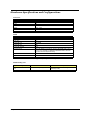
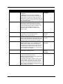
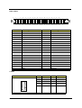
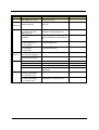
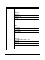
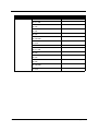
Revision History
Please refer to the table below for the updates made on Aspire T130 service guide.
Date
II
Chapter
Updates
Copyright
Copyright © 2003 by Acer Incorporated. All rights reserved. No part of this publication may be reproduced,
transmitted, transcribed, stored in a retrieval system, or translated into any language or computer language, in
any form or by any means, electronic, mechanical, magnetic, optical, chemical, manual or otherwise, without
the prior written permission of Acer Incorporated.
Disclaimer
The information in this guide is subject to change without notice.
Acer Incorporated makes no representations or warranties, either expressed or implied, with respect to the
contents hereof and specifically disclaims any warranties of merchantability or fitness for any particular
purpose. Any Acer Incorporated software described in this manual is sold or licensed "as is". Should the
programs prove defective following their purchase, the buyer (and not Acer Incorporated, its distributor, or its
dealer) assumes the entire cost of all necessary servicing, repair, and any incidental or consequential
damages resulting from any defect in the software.
Acer is a registered trademark of Acer Corporation.
Intel is a registered trademark of Intel Corporation.
Pentium and Pentium II/III are trademarks of Intel Corporation.
Other brand and product names are trademarks and/or registered trademarks of their respective holders.
III
Conventions
The following conventions are used in this manual:
IV
Screen Messages
Denotes actual messages that appear
on screen.
NOTE
Gives bits and pieces of additional
information related to the current
topic.
WARNING
Alerts you to any damage that might
result from doing or not doing specific
actions.
CAUTION
Gives precautionary measures to
avoid possible hardware or software
problems.
IMPORTANT
Reminds you to do specific actions
relevant to the accomplishment of
procedures.
Preface
Before using this information and the product it supports, please read the following general information.
1.
This Service Guide provides you with all technical information relating to the BASIC CONFIGURATION
decided for Acer's "global" product offering. To better fit local market requirements and enhance product
competitiveness, your regional office MAY have decided to extend the functionality of a machine (e.g.
add-on card, modem, or extra memory capability). These LOCALIZED FEATURES will NOT be covered
in this generic service guide. In such cases, please contact your regional offices or the responsible
personnel/channel to provide you with further technical details.
2.
Please note WHEN ORDERING FRU PARTS, that you should check the most up-to-date information
available on your regional web or channel. If, for whatever reason, a part number change is made, it will
not be noted in the printed Service Guide. For ACER-AUTHORIZED SERVICE PROVIDERS, your Acer
office may have a DIFFERENT part number code to those given in the FRU list of this printed Service
Guide. You MUST use the list provided by your regional Acer office to order FRU parts for repair and
service of customer machines.
V
Table of Contents
Chapter 1
System Specifications
1
Overview . . . . . . . . . . . . . . . . . . . . . . . . . . . . . . . . . . . . . . . . . . . . . . . . . . . .1
Features and Specifications . . . . . . . . . . . . . . . . . . . . . . . . . . . . . . . . . . . . .2
Aspire T130 Front Panel . . . . . . . . . . . . . . . . . . . . . . . . . . . . . . . . . . . . . . . . 4
Aspire T130 Rear Panel . . . . . . . . . . . . . . . . . . . . . . . . . . . . . . . . . . . . . . . . 5
Main Board Layout . . . . . . . . . . . . . . . . . . . . . . . . . . . . . . . . . . . . . . . . . . . . 6
Block Diagram . . . . . . . . . . . . . . . . . . . . . . . . . . . . . . . . . . . . . . . . . . . . . . . . 8
Hardware Specifications and Configurations . . . . . . . . . . . . . . . . . . . . . . . . 9
Power Management Function (ACPI support function) . . . . . . . . . . . . . . . 17
Chapter 2
System Utilities
18
BIOS Navigation keys . . . . . . . . . . . . . . . . . . . . . . . . . . . . . . . . . . . . . . . . . 19
Entering Setup . . . . . . . . . . . . . . . . . . . . . . . . . . . . . . . . . . . . . . . . . . . . . . 20
Product Information . . . . . . . . . . . . . . . . . . . . . . . . . . . . . . . . . . . . . . . . . . 21
Standard CMOS Features . . . . . . . . . . . . . . . . . . . . . . . . . . . . . . . . . . . . .22
IDE Channel 0 Master/Slave and IDE Channel 1 Master/Slave . . . . . . . . .24
Advanced BIOS Features . . . . . . . . . . . . . . . . . . . . . . . . . . . . . . . . . . . . . .25
Advanced Chipset Features . . . . . . . . . . . . . . . . . . . . . . . . . . . . . . . . . . . .28
Integrated Peripherals . . . . . . . . . . . . . . . . . . . . . . . . . . . . . . . . . . . . . . . . 30
Power Management Setup . . . . . . . . . . . . . . . . . . . . . . . . . . . . . . . . . . . . . 35
PnP/PCI Configuration . . . . . . . . . . . . . . . . . . . . . . . . . . . . . . . . . . . . . . . . 39
PC Health Status . . . . . . . . . . . . . . . . . . . . . . . . . . . . . . . . . . . . . . . . . . . . 41
Frequency Control . . . . . . . . . . . . . . . . . . . . . . . . . . . . . . . . . . . . . . . . . . .42
Load Default Settings . . . . . . . . . . . . . . . . . . . . . . . . . . . . . . . . . . . . . . . . . 43
Set Supervisor/User Password . . . . . . . . . . . . . . . . . . . . . . . . . . . . . . . . . . 44
Save&Exit Setup . . . . . . . . . . . . . . . . . . . . . . . . . . . . . . . . . . . . . . . . . . . . . 45
Exit Without Saving . . . . . . . . . . . . . . . . . . . . . . . . . . . . . . . . . . . . . . . . . . . 46
Chapter 3
Machine Disassembly and Replacement
47
General Information . . . . . . . . . . . . . . . . . . . . . . . . . . . . . . . . . . . . . . . . . .48
Before You Begin . . . . . . . . . . . . . . . . . . . . . . . . . . . . . . . . . . . . . . . . . . . .48
Disassembly Procedure Flowchart . . . . . . . . . . . . . . . . . . . . . . . . . . . . . . . 49
Standard Disassembly Procedure . . . . . . . . . . . . . . . . . . . . . . . . . . . . . . . 50
Opening the System . . . . . . . . . . . . . . . . . . . . . . . . . . . . . . . . . . . . . . . 50
Removing the Front Panel . . . . . . . . . . . . . . . . . . . . . . . . . . . . . . . . . . . 50
Removing the Cables . . . . . . . . . . . . . . . . . . . . . . . . . . . . . . . . . . . . . . . 50
Removing the Modem Card, CD-ROM, Floppy and HDD . . . . . . . . . . . 51
Removing the Power Supply . . . . . . . . . . . . . . . . . . . . . . . . . . . . . . . . . 52
Removing the Heatsink and CPU . . . . . . . . . . . . . . . . . . . . . . . . . . . . . . 53
Removing the Memory . . . . . . . . . . . . . . . . . . . . . . . . . . . . . . . . . . . . . . 54
Removing the MainBoard . . . . . . . . . . . . . . . . . . . . . . . . . . . . . . . . . . . 54
Removing the Power Button . . . . . . . . . . . . . . . . . . . . . . . . . . . . . . . . . 54
Removing the LED Module. . . . . . . . . . . . . . . . . . . . . . . . . . . . . . . . . . 54
Removing the Daughter Board . . . . . . . . . . . . . . . . . . . . . . . . . . . . . . . 55
Standard Reassembly Procedures . . . . . . . . . . . . . . . . . . . . . . . . . . . . . . . . 56
Installing the Daughter Board . . . . . . . . . . . . . . . . . . . . . . . . . . . . . . . . . 56
Installing the LED Module . . . . . . . . . . . . . . . . . . . . . . . . . . . . . . . . . . . . 56
Installing the Power Button . . . . . . . . . . . . . . . . . . . . . . . . . . . . . . . . . . . 56
Installing the Mainboard . . . . . . . . . . . . . . . . . . . . . . . . . . . . . . . . . . . . . 56
Installing the CPU and Heatsink module. . . . . . . . . . . . . . . . . . . . . . . . . 57
Installing the Memory . . . . . . . . . . . . . . . . . . . . . . . . . . . . . . . . . . . . . . . 57
Installing the Power Supply . . . . . . . . . . . . . . . . . . . . . . . . . . . . . . . . . . . 57
Installing the Modem Card, CD-ROM, Floppy and HDD . . . . . . . . . . . . . 58
VII
Table of Contents
Installing the Cables . . . . . . . . . . . . . . . . . . . . . . . . . . . . . . . . . . . . . . . . 59
Install the Front Panel . . . . . . . . . . . . . . . . . . . . . . . . . . . . . . . . . . . . . . 60
Closing the System . . . . . . . . . . . . . . . . . . . . . . . . . . . . . . . . . . . . . . . . . 60
Chapter 4
Troubleshooting
61
Power-On Self-Test (POST) . . . . . . . . . . . . . . . . . . . . . . . . . . . . . . . . . . . . 62
POST Check Points . . . . . . . . . . . . . . . . . . . . . . . . . . . . . . . . . . . . . . . . . .63
POST Error Messages List . . . . . . . . . . . . . . . . . . . . . . . . . . . . . . . . . . . . . 65
Error Symptoms List . . . . . . . . . . . . . . . . . . . . . . . . . . . . . . . . . . . . . . . . . .69
Chapter 5
Jumper and Connector Information
76
Header Definition . . . . . . . . . . . . . . . . . . . . . . . . . . . . . . . . . . . . . . . . . . . . . 77
Chapter 6
FRU (Field Replaceable Unit) List
86
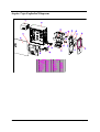
Exploded Diagram . . . . . . . . . . . . . . . . . . . . . . . . . . . . . . . . . . . . . . . . . . . . . 87
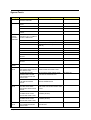
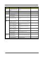
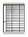
Spare Parts . . . . . . . . . . . . . . . . . . . . . . . . . . . . . . . . . . . . . . . . . . . . . . . . . . 88
Appendix A
Model Definition and Configuration
92
Appendix B
Test Compatible Components
93
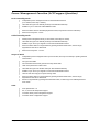
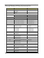
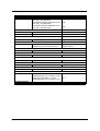
Microsoft Windows XP Home Environment Test . . . . . . . . . . . . . . . . . . . . . 94
Appendix C
VIII
Online Support Informatoin
99
Chapter 1
System Specifications
Overview
Aspire T130 will use AK32 (Aspire T310) chassis. It will be a low cost K8 solution with memory card reader
and firewire solution.
Aspire T130 is a versatile, high-power system, supporting AMD K8 CPUs (754). The computer uses
Peripheral Component Interface (PCI) and Accelerated Graphics Port (AGP) design. This improves system
efficiency and helps the system support varied multimedia and software applications.
Aspire T130 has standard I/O interfaces such as a serial port, parallel port, PS/2 keyboard and mouse ports,
the system includes eight USB port(2 front access, 2 I/O bracket and the rest four have
been occupied by devices), two microphone ports and stereo line-out jacks (one at front and one at
rear panel) and a stereo line-in Jack (in rear panel) . The system can accommodate extra peripheral
equirement through those I/O ports. The system can also support an optional high-speed fax/data modem or
an additional LAN (local area network) card. Furthermore, the system is compatible with Windows XP Home
operating systems.
Chapter 1
1
Features & Specifications
CPU
T
Support AMD Athlon 64 Processor
T
Front Side Bus: 800MHz
T
Socket type: K8 Socket 754
Chipset
T
North Bridge: SiS755
T
South Bridge: SiS964(L)
T
AC’97 Audio Codec: ALC655
Memory
T
Module Speed: DDR 200/266/333/400
T
Socket Type: Two DDR 184-pin unbuffered DIMM sockets
T
Maximum Memory Size: 2GB
BIOS
T
BIOS Memory Size:2MB
T
Kernel:Award Kernel with Acer skin
PCI Slot
T
PCI Slots Quality: 3 pcs
T
PCI Slot Type:PCI 2.2 5V slot
AGP Slot
T
AGP Slot Type: AGP 8x 1.5V slot
T
AGP Slot Quality:1
T
Speed: 4x/8x
T
Headers: Two 40-pin IDE low profile headers
T
Devices: Up to 4 IDE devices
T
Speed: PIO mode ATA 66/100/133
IDE
Audio Connectors and Headers
T
Real Audio Connector: Line Out, Line In, Microphone In
T
One CD-In Header
T
One AUX In Header
T
One SPDIF Header
T
One Intel specification audio header
T
LAN Phy: RealTek RTL8201BL/CT
T
10/100 Mbs support
LAN
2
Chapter 1
T
One RJ45 jack at the rear side
USB Connectors and Headers
T
Support USB 2.0/1.1 and mixed mode
T
8 USB ports support
T
Two USB ports at the rear panel
T
Two USB ports at the front through daughter card(on-board)
T
Four on-board USB ports reserved for memory card reader
Modem
T
Askey V.92 56K HSF Fax/Modem
T
GVC V.92 56K HSF Fax/Modem
Memory Card Reader
T
ECS 6-in-1 Memory Card Reader with 1394
Power Supply
T
230W in stable mode
T
One 34-pin FDD low profile header
T
Three 3-pin FAN header: CPU, Chassis, Power
T
One COM connector, one COM header
T
One LPT connector
T
One PS/2 keyboard and mouse connector
T
One front panel header
T
One 20-pin ATX power supply connector; one 4-pin 12V power supply connector
T
One 1394 connector (optional), one 1394 header (optional)
T
One 10/100 fast Ethernet LAN Port
T
One Buzzer
Misc
Chapter 1
3
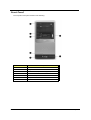
Front Panel
The computer’s front panel consists of the following:
No.
Description
Label
4
No.
Description
Description
1
Optical Drive
2
Floppy Drive
3
6-in-1 Card Reader (Manufacturing Option)
4
Power Button
5
Speaker or Headphone Jack
6
Microphone Jack
7
USB Ports
Chapter 1
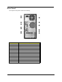
Rear Panel
The computer’s rear panel consists of the following:
Label
No.
Description
No.
Description
Description
1
Power Cord Socket
2
Voltage Selector Switch
3
Fan Aperture
4
PS/2 Keyboard Port
5
PS/2 Mouse Connector
6
Serial Connector
7
Printer Connector
8
IEEE 1394 Port
9
USB Connectors
10
RJ-45 Ethernet Connector
11
Microphone Jack
12
Line-out Jack
13
Line-In Jack
14
Monitor Connector
Chapter 1
5
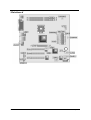
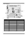
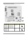
Mainboard
6
Chapter 1
Lable
AGP1
Component
Accelerated Graphics Port (supports 1.5V AGP card only)
ATX1
Standard 20-pin ATX power connector
ATX2
Standard 4-pin ATX Power Connector
AUDIO1
Front Audio Connector
CASFAN1
Case fan connector
CDIN1
Primary CD-in connector
CPU FAN1
Cooling fan for CPU
DIMM1~DIMM2
Three 184-pin DDR SDRAM
FDD1
Floppy disk drive connector
IDE1
Primary IDE channel
IDE2
Secondary IDE channel
JP1
Clear CMOS jumper
PANEL1
Connector for case front panel switches and LED indicators
PCI1~ PCI3
Standard PCI Slot
USB1
USB header follow acer’s spec.
USB3
USB header follow acer’s spec.
USB4
USB header follow Intel’s spec.
PWRFAN1
3 pin header for 3rd fan
JP3
BIOS protection header
COM2
5x2 COM2 header follow acer’s spec.
1394A2
Standard header for 1394
AUXIN1
Audio Header
SPDIFO1
3 pin speaker header follow acer’s spec.
Chapter 1
7
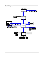
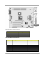
Block Diagram
鶗廱嚽嚾黦龑顣鰎齙儹黤齝
鰗齠麚鼮囃麚龑
DDR SDRAM
AMD-ATHLON64-CPU
DIMM 1
LINK0
DIMM 2
16*16
IN
Rtt
SSTL-2 Termination
OUT
AGP BUS
AGP 8X SLOT
SIS755
MuTIOL
1GMHz
LAN PHY
1394 connector
1394 header
AC'97
Audio Codec
PCI VT6307
PCI SLOT 3
PCI SLOT 2
PCI SLOT 1
SiS964L
PS/2
IDE 1
IDE 2
KEYBOARD
/MOUSE
FAN
2
FAN
3
FAN CONTROL
USB 2
USB 4
USB 6
USB 1
USB 3
USB 5
USB 7
Optional
LPC Bus
FAN
1
USB 0
VOLTAGE MONITOR
TEMPERATURE MONITOR
LPC Super I/O
Legacy
ROM
ISA Bus
PARALLEL
8
COM1/2
FLOPPY
Chapter 1
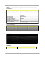
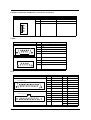
Hardware Specifications and Configurations
Processor
Item
Specification
Type
AMD Athlon 64
Socket
754
Speed
3000+~3400+ or above
Voltage
1.40V~1.55V
Front Side Bus
800MHz
BIOS
Item
Specification
BIOS code programmer
Award
BIOS vision
v6.0
BIOS ROM type
Flash ROM
BIOS ROM size
2MB
BIOS ROM package
PLCC
Support Protocol
ACPI 1.0b, APM1.2, PC Card 95, AC972.3, EPP/IEEE 1284 1.7& 1.9,
PCI 2.2, PnP 1.0a,DMI 2.0,USB,DDC-2B,ODD-bootable, Windows
keyboard, Microsoft Simple Boot Flag
Support to LS-120 drive
Yes
Support to BIOS boot block feature
Yes
NOTE: The BIOS can be overwritten/upgraded by using the flash utility.
BIOS Hotkey List
Hotkey
c
Chapter 1
Function
Enter BIOS Setup Utility
Description
Press while the system is booting to enter
BIOS Setup Utility.
9
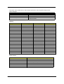
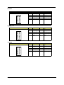
This section has two table lists, system memory specification and the possible combinations of memory
module.
System Memory
Item
Specification
Memory socket number
2 sockets
Memory Controller
K8 CPU
Support memory size per socket
1G
Support maximum memory size
2G
Support memoryType
DDR SDRAM(Double Data Rate-Synchronous Dynamic Random
Access Memory)
Support memory Speed
100/133/166/200 MHz
Support memory voltage
2.6 V
Support memory module package
184-pin DIMM
Support to parity check feature
Yes
Support to Error Correction Code (ECC) feature
Yes
Memory module combinations
You can install memory modules in any combination as long as they
match the above specifications.
Memory Combinations
Slot1
Slot 2
Total Memory
256 / 512 / 1024MB
0M
256/512/1024MB
256 / 512 / 1024MB
256MB
512/768/1280MB
256 / 512 / 1024MB
512MB
768/1024/1536MB
256 / 512 / 1024MB
1024MB
1280/1536/2048MB
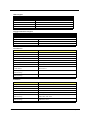
Cache Memory
Item
Specification
First-Level Cache Configurations
Cache function control
Enable/Disable by BIOS Setup
Second-Level Cache Configurations
L2 Cache RAM type
PBSRAM
L2 Cache RAM size
256KB/512KB/1MB
L2 Cache RAM speed
One-half the processor core clock frequency
L2 Cache function control
Enable/Disable by BIOS Setup
L2 Cache scheme
Fixed in write-back
Video Memory
Item
Memory Size
10
Specification
8MB or above
Chapter 1
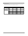
This section has two table lists, the video interface specification and its supported display modes.
Video Interface
Item
Specification
Video controller
N/A
Video controller resident bus
AGP Bus
Video interface support
Video YUV texture in all texture formats
H/W DVD accelerator
Display
Display Screen Resolution
Refresh Rate (Hz)
Hor. Scan (KHz)
Pixel Clock (MHz)
640x480
60
31.5
25.2
640x480
72
37.4
32.0
640x480
75
37.5
31.5
640x480
85
43.3
36.0
640x480
120
63.7
55.0
800x600
56
35.2
36.0
800x600
60
37.8
39.9
800x600
72
48.0
50.0
800x600
75
46.9
49.5
800x600
85
53.7
56.2
800x600
100
62.5
67.5
800x600
120
76.1
81.0
800x600
160
101.9
110.0
1024x768
70
56.5
75.0
1024x768
75
60.0
78.8
1024x768
100
79.0
110.0
1280x1024
43
50.0
80.0
1280x1024
60
64.0
110.0
1280x1024
85
91.2
157.5
1600x1200
60
76.2
156.0
1600x1200
85
106.2
229.5
Audio Interface
Item
Specification
Audio controller
Realtek ALC655
Audio controller resident bus
AC’97
Audio function control
Enable/disable by BIOS Setup
Mono or stereo
Stereo
Resolution
26 bits
Channel
6
Chapter 1
11
IDE Interface
Item
Chip Vendor
Specification
SiS
Chip Name
SiS964L
Number of IDE channel
2
Support IDE interface
Yes
Support bootable CD-ROM
Yes
Floppy Disk Drive Interface
Item
Vendor & Mode Name
Specificatoin
Panasoic JU-226A 243FC
Floppy Disk Specification
Floppy Disk Drive Controlle
ITE8705
Floppy Disk Drive Controller Resident Bus
ISA Bus
Support FDD format
360KB, 720KB, 1.2MB, 1.44MB, 2.88MB
Parallel Port
Item
Specification
Parallel port controller
ITE8705
Parallel port controller resident bus
ISA bus
Number of parallel ports
1
Location
Rear Side
Support ECP/EPP
SPP / Bi-directional / ECP / EPP
Connector type
25-pin D-type female connector
Parallel port function control
Always Enabled
Optional ECP DMA channel
DMA channel 1
(in BIOS Setup)
DMA channel 3
Optional parallel port I/O address
378h
(via BIOS Setup)
Optional parallel port IRQ
IRQ7
(via BIOS Setup)
Serial Port
Item
12
Specification
Serial port controller
ITE8705
Serial port controller resident bus
ISA bus
Number of serial port
1
16550 UART support
No
Connector type
9-pin D-type female connector
Optional serial port I/O address
COM1: 2F8h, 3E8h, 2E8h
(via BIOS Setup)
COM2: 3E8h, 3F8h, 2F8h
Optional serial port IRQ
COM1: IRQ 3, and 4
(via BIOS Setup)
COM2: IRQ 4, and 3
Chapter 1
Modem
Item
Specification
Chipset
Agere Scorpio+CSP1037P
Fax modem data baud rate (bps)
14.4K
Data modem data baud rate (bps)
56K
Voice modem
V.253
Modem connector type
RJ11
Full duplex
No
USB Port
Item
Specification
USB Compliancy Level
USB 1.1/2.0
EHCI
USB 2.0
Number of USB Port
8 ( M/B support total 8 USB but there only 4 can be used, another 4 have
been occupied by memory card reader)
Location
Rear Side(2) /Front side(2)
Serial Port Function Control
Always Enabled
PCI INTx# and IDSEL Assignment Map
PCI INTx #
PCI Devices
INTA#
Device IDSEL: ADxx
AGP-slot
N
INTB#
PCI-Slot1
AD20
INTC#
PCI-Slot2
AD21
INTD#
PCI-Slot3
AD22
PCI Slot IRQ Routing Map
PCI INTX#
INTA
INTB
INTC
INTD
Bus Mastering
PCI slot 1
Route 4
Route 1
Route 2
Route 3
Enabled
PCI slot 2
Route 3
Route 4
Route 1
Route 2
Enabled
PCI slot 3
Route 2
Route 3
Route 4
Route 1
Enabled
I/O Address Map
Hex Range
Devices
000-01F
DMA Controller-1
020-021
Interrupt Controller-1
040-043
System Timer
060-060
Keyboard Controller 8742
061-061
System Speaker
070-071
CMOS RAM Address and Real Time Clock
080-08F
DMA Page Register
0A0-0A1
Interrupt Controller-2
0C0-0DF
DMA Controller-2
0F0-0FF
Math Co-Processor
Chapter 1
13
I/O Address Map
Hex Range
Devices
170-177
Secondary IDE
1F0-1F7
Primary IDE
278-27F
Parallel Printer Port 2
2F8-2FF
Serial Asynchronous Port 2
378-37F
Parallel Printer Port 1
3F0-3F5
Floppy Disk Controller
3F6-3F6
Secondary IDE
3F7-3F7
Primary IDE
3F8-3FF
Serial Asynchronous Port 1
0CF8
Configuration Address Register
0CFC
Configuration Data Register
778-77A
Parallel Printer Port 1
IRQ Assignment Map
IRQx
System Devices
Add-On-Card Devices
IRQ0
Timer
N
IRQ1
Keyboard
N
IRQ2
Cascade Interrupt Control
N
IRQ3
Serial Alternate
Reserved
IRQ4
Serial Primary
Reserved
IRQ5
MPU-401(Alternate)
Reserved
IRQ6
Floppy Disk
Reserved
IRQ7
Parallel Port
ReservedReserved
IRQ8
Real Time Clock
N
IRQ9
N
Reserved
IRQ10
N
Reserved
IRQ11
N
Reserved
IRQ12
PS/2 Mouse
Reserved
IRQ13
Math Coprocessor Exception
N
IRQ14
Primary IDE
Reserved
IRQ15
Secondary IDE
Reserved
NOTE: N - Not be used
14
Chapter 1
DRQ Assignment Map
DRQx
System Devices
Add-On-Card Devices
IRQ0
N
Reserved
IRQ1
N
Reserved
IRQ2
FDD
N
IRQ3
N
Reserved
IRQ4
Cascade
N
IRQ5
N
Reserved
IRQ6
N
Reserved
IRQ7
N
Reserved
NOTE: N - Not be used
Mainboard Major Chips
Item
Controller
System core logic
SiS755
Video controller
N/A
Super I/O controller
ITE8705
Audio controller
RealTek AC655
HDD controller
SiS964L
Keyboard controller
SiS964L
RTC
SiS964L
IEEE1394
VIA6307
Environment Requirements
Item
Specification
Temperature
Operating
+5 ~ +35°C
Non-operating
-20 ~ +60°C (Storage package)
Humidity
Operating
0% to 90% RH
Non-operating
20% to 90% RH
Vibration
Operating (unpacked)
5-500Hz, 1.0Grms (random)
Non-operating (packed)
5-500Hz, 2.16Grms (random)
Switching Power Supply 200W
Input Frequency
Frequency Variation Range
50MHz
47MHz to 53MHz
60MHz
57MHz to 63MHz
Input Voltage
100 - 120 VRMS
Chapter 1
Variation Range
90 - 132 VRMS
15
Input Voltage
200 - 240 VRMS
Variation Range
180 - 264 VRMS
Input Current
Measuring Range
4A
90 -132 VRMS
2A
180 - 264 VRMS
NOTE: Measure at line input 90 VRMS and maximum load condition.
16
Chapter 1
Power Management Function (ACPI support function)
Device Standby Mode
T
Independent power management timer for hard disk drive devices
(0-15 minutes, time step=1 minute).
T
Hard disk drive goes into Standby mode (for ATA standard interface).
T
Disable V-sync to control the VESA DPMS monitor.
T
Resume method: device activated (Keyboard for DOS, keyboard & mouse for Windows).
T
Resume recovery time: 3-5 sec.
Global Standby Mode
T
Global power management timer (2-120 minutes, time step=10 minute).
T
Hard disk drive goes into Standby mode (for ATA standard interface).
T
Disable H-sync and V-sync signals to control the VESA DPMS monitor.
T
Resume method: Return to original state by pushing external switch button, modem ring in,
keyboard and mouse for APM mode.
T
Resume recovery time: 7-10 sec.
Suspend Mode
T
Independent power management timer (2-120 minutes, time step=10 minutes) or pushing external
switch button.
T
CPU goes into SMM.
T
CPU asserts STPCLK# and goes into the Stop Grant State.
T
LED on the panel turns amber colour.
T
Hard disk drive goes into SLEEP mode (for ATA standard interface).
T
Disable H-sync and V-sync signals to control the VESA DPMS monitor.
T
Ultra I/O and VGA chip go into power saving mode.
T
Resume method: Return to original state by pushing external switch button, modem ring in,
keyboard and mouse for APM mode.
T
Return to original state by pushing external switch button, modem ring in and USB keyboard for
ACPI mode.
T
ACPI specification 1.0.
T
S0, S1, S3 and S5 sleep state support.
T
On board device power management support.
T
On board device configuration support.
ACPI
Chapter 1
17
Chapter 2
System Utilities
Most systems are already configured by the manufacturer or the dealer. There is no need to run
Setup when starting the computer unless you get a Run Setup message.
The Setup program loads configuration values into the battery-backed nonvolatile memory called CMOS RAM.
This memory area is not part of the system RAM.
NOTE: If you repeatedly receive Run Setup messages, the battery may be bad/flat. In this case, the system
cannot retain configuration values in CMOS.
Before you run Setup, make sure that you have saved all open files. The system reboots immediately
after you exit Setup.
Chapter 2
18
BIOS Navigation Keys
The BIOS navigation keys are listed below:
Key
19
Function
^
Exits the current menu
zxwy
Scrolls through the items on a menu
+-{}
Modifies the selected field’s values
u
Saves the current configuration and exits setup
l
Displays a screen that describes all key functions
p
Loads previously saved values to CMOS
q
Loads a minimum configuration for troubleshooting
r
Loads an optimum set of values for peak performance
Chapter 2
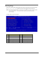
Entering Setup
Power on the computer and the system will start POST (Power On Self Test) process. When the message
of “Press DEL to enter SETUP” appears on the screen, press c to enter the setup menu.
NOTE: If the message disappears before you respond and you still wish to enter Setup, restart the system
by turning it OFF and On. You may also restart the system by simultaneously pressing
[Ctrl+Alt+Delete].
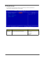
The Setup Utility main menu then appears:
Item
Parameter
Item
Parameter
1
Production Information
8
PC Health Status
2
Standard CMOS Features
9
Frequency Control
3
Advanced BIOS Features
10
Load Default Settings
4
Advanced Chipset Features
11
Set Supervisor Password
5
Integrated Peripherals
12
Set User Password
6
Power Management Setup
13
Save & Exit Setup
7
PnP/PCI Configurations
14
Exit Without Saving
Chapter 2
20
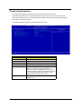
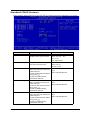
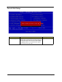
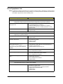
Product Information
The screen below appears if you select Product Information from the main menu:
The Product Information menu contains general data about the system, such as the product name,
serial number, BIOS version, etc. These information is necessary for troubleshooting (may be required
when asking for technical support).
The following table describes the parameters found in this menu:
Parameter
21
Description
Product Name
Displays the model name on your system
System S/N
Displays the system’s S/N
Main Board S/N
Displays your main board’s serial number
System BIOS Version
Specifies the version of your BIOS utility
SMBIOS Version
The System Management Interface (SM) BIOS
allows you to check your system hardware
components without actually opening your system.
Hardware checking is done via software during start
up. This parameter specifies the version of the
SMBIOS utility installed in your system
BIOS Release Date
Displays the release date of the BIOS utility
MMM DD,YYYY
Chapter 2
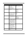
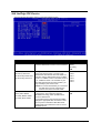
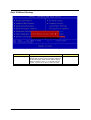
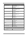
Standard CMOS Features
Select Standard CMOS Features from the main menu to configure some basic parameters in your system.
Parameter
Description
Option
Date
Let’s you set the date following the
weekday-month-day-year format
Weekday: Sun, Mon, ....Sat
Month: Jan, Feb,....Dec
Day: 1 to 30
Year: 1980 to 2079
Time
Let’s you set the time following the
hour-minute-second format
Hour: 0 to 23
Minute: 0 to 59
Second: 0 to 59
IDE Channel 0 Master
Lets you configure the hard disk
(Show the Status:)
drive connected to the master port None
of IDE channel 0.
HDD or CD-ROM Number
To enter the IDE Channel 0 Master
setup, press e.
The IDE CD-ROM is always
automatically detected.
IDE Channel 0 Slave
Lets you configure the hard disk
drive connected to the slave port
of IDE channel 0.
To enter the IDE Channel 0 Slave
setup, press e.
The IDE CD-ROM is always
automatically detected.
IDE Channel 1 Master
Lets you configure the hard disk
(Show the Status:)
drive connected to the master port None
of IDE channel 1.
HDD or CD-ROM Number
To enter the IDE Channel 1 Master
setup, press e.
The IDE CD-ROM is always
automatically detected.
Chapter 2
(Show the Status:)
None
HDD or CD-ROM Number
22
Parameter
23
Description
Option
IDE Channel 1 Slave
Lets you configure the hard disk
drive connected to the slave port
of IDE channel 1.
To enter the IDE Channel 1 Slave
setup, press e.
The IDE CD-ROM is always
automatically detected.
(Show the Status:)
None
HDD or CD-ROM Number
Drive A
Allows you to configure your
floppy drive A.
None
360K, 5.25in
1.2M , 5.25 in.
720K , 3.5 in.
1.44M, 3.5 in.
2.88M, 3.5 in.
Video
This item specifies the type of
video card in use. The default
setting is VGA/EGA. Since current
PCs use VGA only, this function is
almost useless and may be
disregarded in the future.
EGA/VGA
CGA 40
CGA 80
MONO
Halt On
This parameter enables you to
control the system stops in case of
Power On Self Test errors
(POST).
All Errors
No Errors
All ,But keyboard
All ,But Diskette
All ,but Disk/Key
Base Memory
Refers to the portion of memory
that is available to standard DOS
programs. DOS systems have an
address space of 1 MB, but the
top 384 KB (called high memory)
is reserved for system use. This
leaves 640 KB of conventional
memory. Everything above 1 MB
is either extended or expanded
memory.
N/A
Extended Memory
Memory above and beyond the
N/A
standard 1 MB (megabyte) of base
memory that DOS supports.
Extended memory is not
configured in any special manner
and is therefore unavailable to
most DOS programs. However,
MS Windows and OS/2 can use
extended memory.
Total Memory
Total base, and extended memory, N/A
and I/O ROM 384KB available to
the system.
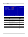
Chapter 2
IDE Channel 0 Master/Slave and IDE Channel 1 Master/Slave
The following screen appears if you select any of the IDE drive parameters:
The following table describes the parameters found in this menu.
Parameter
Description
Option
IDE HDD Auto-Detection
Auto-detects your hard disk drive.
[Press Enter]
IDE Channel 0 Master/Slave
IDE Channel 1 Master/Slave
Displays the device type
None
Auto
Manual
Access Mode
Selects the HDD access mode
CHS
LBA
Large
Auto
Capacity
Shows the size of your hard disk in MB.
xxxxxx MB
Cylinder
Shows your hard disk’s number of
cylinders.
0 to 65535
Head
Shows your hard disk’s number of heads
0 to 255
Precomp
Selects the Precomp number for old HDD
parking
0 to 65535
Landing Zone
Selects the Landing Zone number for old
HDD parking
0 to 65535
Sector
Shows your hard disk’s number of sectors
0 to 255
Chapter 2
24
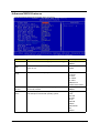
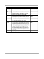
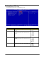
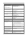
Advanced BIOS Features
This option defines advanced information about your system.
Parameter
25
Description
Options
Silent Boot
This is to switch 1st screen logo (default Acer's logo)
Disabled
Enabled
Configuration
Table
This is to select if system configuration shown by 2nd
screen or not.
Disabled
Enabled
Hard Disk Boot
Priority
Selects the hard disk boot priority
Press Enter
Pri. Master
Pri. Slave
Sec. Master
Sec. Slave
USBHDD0/1/2
Bootable Add-in Cards
Quick Power on
Self Test
This parameter speeds up POST by skipping some items that
are normally checked.
Disabled
Enabled
First Boot
Device
The items allow you to set the sequence of boot device where
BIOS attempts to load the disk operating system.
Floppy
LS120
Hard Disk
CD ROM
ZIP100
USB-FDD
USB-ZIP
USB-CDROM
LAN
Disabled
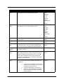
Chapter 2
Parameter
Description
Options
Second Boot
Device
The items allow you to set the sequence of boot device where
BIOS attempts to load the disk operating system.
Floppy
LS120
Hard Disk
CD ROM
ZIP100
USB-FDD
USB-ZIP
USB-CDROM
LAN
Disabled
Third Boot
Device
The items allow you to set the sequence of boot device where
BIOS attempts to load the disk operating system.
Floppy
LS120
Hard Disk
CD ROM
ZIP100
USB-FDD
USB-ZIP
USB-CDROM
LAN
Disabled
Boot Other
Device
This parameter allows you to specify the system boot up
search sequence.
Disabled
Enabled
Swap Floppy
Driver
Setting to Enabled will swap floppy drive a: and b:
Disabled
Enabled
Boot Up Floppy
Seek
If this item is enabled, it checks the size of the floppy disk
drives at start-up time. You don’t need to enable this item
unless you have a legacy diskette drive with 360K capacity.
Disabled
Enabled
Boot up
NumLock
Status
This item defines if the keyboard Num Lock key is active when
your system is started.
Off/On
Gate A20
Option
This item is to set the Gate A20 status. A20 refers to the first
64KB of extended memory. When the default value Fast is
selected, the Gate A20 is controlled by port 92 or chipset
specific method resulting in faster system performance.
When Normal is selected, A20 is controlled by a keyboard
controller or chipset hardware.
Fast
Normal
Typematic Rate
Setting
If this item is enabled, you can use the following two items to
set the typematic rate and the typematic delay settings for
your keyboard.
Disabled
Enabled
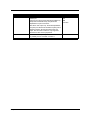
Chapter 2
T
Typematic Rate (Chars/Sec) : Use this item to
define how many characters per second are
generated by a held-down key.
T
Typematic Delay (Msec): Use this item to
define how many milliseconds muse elapse
before a held-down key begins generating
repeat characters.
26
27
Parameter
Description
Options
Typematic Rate
(Chars/sec)
After Typematic Rate Setting is enabled, this item allows you
to set rate (characters/second) at which at keys are
accelerated.
Settings:
6,8,10,12,15,20,24 and
30
Typematic
Delay
This item allows you to select the delay between when the
key was first pressed and when the acceleration begins.
Settings:
250,500,750 and 1000
Security Option
If you have installed password protection, this item defines if
the password is required at system start up, or if it is only
required when a user tries to enter the Setup Utility.
Setup
System
APIC Mode
This items allows you to enable APIC (Advanced
Programmable Interrupt Controller) functionality. APIC is an
Intel chip that provides symmetic multiprocessing (SMP) for
its Pentium systems.
Enabled
Disabled
OS Select For
DRAM > 64MB
This item is only required if you have installed more than
64MB of memory and you are running the OS/2 operating
system. Otherwise, leave this item at the default.
Non-OS2
OS2
HDD S.M.A.R.T
Capability
The S.M.A.R.T (Self-Monitoring, Analysis, and Reporting
Technology) system is a diagnostics technology that monitors
and predicts device performance. S.M.A.R.T software resides
on both the disk drive and the host computer.
The disk drive software monitors the internal performance of
the motors, media, heads, and electronics of the drive. The
host software monitors the overall reliability status of the
drive. If a device failure is predicated, the host software,
through the Client WORKS S.M.A.R.Tapplet, warns the user
of the impending condition and advise appropriate action to
protect the data.
Disabled
Enabled
Video BIOS
Shadow
This function, when enabled allows VGA BIOS to be copied to
the system DRAM for enhanced performance.
Disabled
Enabled
Chapter 2
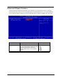
Advanced Chipset Features
These items define critical timing parameters of the mainboard. You should leave the items on this page
at their default values unless you are very familiar with the technical specifications of your system hardware.
If you change the values incorrectly, you may introduce fatal errors or recurring instability into your system.
Parameter
Description
Option
DRAM Configuration
DRAM timing and control
Press Enter
AGP Aperture Size
This item defines the size of the aperture if
you use an AGPgraphics adapter. The AGP
aperture refers to a section of the PCI
memory address range used for graphics
memory.
32MB
64MB
128MB
256MB
512MB
Chapter 2
28
DRAM Configuration
Parameter
29
Description
Option
HT_Width
This item shows Hyper Transport TM ‘s bus size of
Local Descriptor Table (LDT). The bus size is
automatically calculated by the CPU. Therefore, we
strongly recommend that you do not change this
setting.
8 bits
16 bits
Auto
HT_Speed
This item shows the bus frequency of Local
Descriptor Table(LDT). Its default is setting as
800MHz.
200 MHz
400 MHz
600 MHz
800 MHz
DDR Timing
Setting by
Set this to the default value to enable the system to
automatically set the DDR timing by SPD(Serial
Presence Detect). SPD is an EEPROM chip on the
DIMM module that stores information about the
memory chips it contains, including size, speed,
voltage, row and column addresses, and
manufacture. If you disable this item, you can use
the following three items to manually set the timing
parameters for the system memory.
Manual
Auto
Max Memclock
(Mhz)
When DDR Timing Setting by is set to Manual, use
this item to set the DRAM frequency.
200
Chapter 2
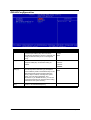
Integrated Peripherals
These options display items that define the operation of peripheral components on the system’s input/
output ports.
Parameter
Description
Option
SIS OnChip IDE Device
Press enter to setup the IDE device
Press Enter
SIS OnChip PCI Device
Press enter to setup the PCI device
Press Enter
Onboard SuperIO Device Press enter to setup the superIO device
Press Enter
IDE HDD Block Mode
If your IDE hard drive supports block mode select
Enabled for automatic detection of the optimal
number of block read/writes per sector the drive can
support
Disabled
Enabled
Init Display First
Use this item to specify whether your graphics
adapter is installed in one of the PCI slot or is
integrated on the mainboard.
PCI Slot
AGP
Onboard LAN
Enables and disables the onboard LAN.
Enabled
Disabled
Onboard 1394
Enables or disables the onboard 1394.
Enabled
Disabled
Chapter 2
30
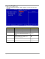
SiS OnChip IDE Device
Scroll to this item and press <Enter> to view the following screen:
Parameter
31
Description
Option
Internal PCI/IDE
These parameters allow you have these options Disabled
to set the IDE devices connect to the connectors Primary
Secondary
Both
IDE Primary Master PIO
IDE Primary Slave PIO
IDE Secondary Master PIO
IDE Secondary Slave PIO
Setting these items to Auto activates the HDD
speed auto-detect function. The PIO mode
specifies the data transfer rate of the HDD. For
example, mode 0 data transfer rate is 3.3 MB/s,
mode 1 is 5.2 MB/s, mode 2 is 8.3 MB/s, mode 3
is 11.1 MB/s and mode 4 is 16.6 MB/s. If your
hard disk performance becomes unstable, you
may manually try the slower mode.
Caution: It is recommended that you connect the
first IDE device of each channel to the
endmost connector of the IDE cable.
Auto
Mode 0
Mode 1
Mode 2
Mode 3
Mode 4
Primary Master UDMA
Primary Slave UDMA
Secondary Master UDMA
Secondary Slave UDMA
Each IDE channel supports a master device and
a slave device. This mainboard supports
UltraDMA technology, which provides faster
access to IDE devices.
If you install a device that supports Ultra DMA,
change the appropriate item on this list to Auto.
You may have to install the Ultra DMA driver
supplied with this mainboard in order to use an
UltraDMA device.
Diabled
Auto
Chapter 2
SiS OnChip PCI Device
Scroll to this item and press <Enter> to view the following screen:
Parameter
Description
Option
USB Controller
This item is used to enable or disable the On-chip
USB.
Disabled
Enabled
USB 2.0 Supports
Enable this item if you plan to use the Universal
Serial Bus ports on this mainboard.
Disabled
Enabled
USB Legacy Support
This item allows the BIOS to interact with a USB
keyboard or mouse to work with MS-DOS based
utilities and non-Windows modes.
Disabled
Enabled
USB Mouse Support
Enable this item if you plan to use a mouse
connected through the USB port in a legacy
operating system (such as DOS) that does not
support Plug and Play.
Disabled
Enabled
SIS AC97 AUDIO
Enables and disables the onboard AC97 audio
Disabled
function. Disable this item if you are going to install a Enabled
PCI audio add-on card.
SIS Serial ATA Controller Hidden ( acer won’t support)
Disabled
Enabled
SIS Serial ATA Mode
IDE
RAID
Chapter 2
Hidden ( acer won’t support)
32
Onboard SuperIO Device
Scroll this item and press <Enter> to view the following screen:
Parameter
33
Description
Option
Onboard FDC Controller
This option enables the onboard floppy disk drive
controller.
Disabled
Enabled
Onboard Serial Port 1
This option is used to assign the I/O address and
interrupt request (IRQ) for the onboard serial port 1
(COM1).
Disabled
3F8/IRQ4
2F8/IRQ3
3E8/IRQ4
2E8/IRQ3
Auto
Onboard Serial Port 2
This option is used to assign the I/O address and
interrupt request (IRQ) for the onboard serial port 2
(COM2).
Disabled
3F8/IRQ4
2F8/IRQ3
3E8/IRQ4
2E8/IRQ3
Auto
Onboard Parallel Port
This option is used to assign the I/O address and
interrupt request (IRQ) for the onboard parallel port.
Disabled
378/IRQ7
278/IRQ5
3BC/IRQ7
Chapter 2
Parameter
Description
Option
Parallel Port Mode
Enables you to set data transfer protocol for your
parallel port.
There are four options: SPP (Standard Parallel Port),
EPP(Enhanced Parallel Port), ECP(Extended
Capabilities Port) and ECP+EPP.
SPP allows data output only. Extended Capabilities
Port (ECP) and Enhanced Parallel Port (EPP) are bidirectional modes, allowing both data input and
output. ECP and EPP modes are only supported
with EPP and ECP aware peripherals.
SPP
EPP
ECP
ECP+EPP
ECP Mode Use DMA
When the onboard parallel port is set to ECP mode,
the parallel port can use DMA 3 or DMA 1.
1
3
Chapter 2
34
Power Management Setup
This option lets you control system power management. The system has various power-saving modes
including powering down the hard disk, turning off the video, suspending to RAM, and software power
down that allows the system to be automatically resumed by certain events.
Parameter
35
Description
Option
ACPI Suspend Type
This item specifies the power saving modes for ACPI
function. S1(POS): The S1 sleep mode is a low
power state. In this state, no system context (CPU or
chipset) is lost and hardware maintains all system
context. S3 (STR): The S3 sleep mode is s powerdown state in which power is supplied only to
essential components such as main memory and
wake-capable devices and all system context is
saved to main memory. The information stored in
memory will be used to restore the PC to the
previous state when an wake-up event occurs.
S1&S3: Both S1 and S3 will be adopted.
S1(POS)
S3(STR)
S1&S3
Video Off Option
This item is to control the mode in which the monitor
will shut down.
Always On: Always keep the monitor on.
Suspend --> Off: During suspend mode, the
monitorwill shut down.
Always On
Suspend > Off
Susp, Stby > Off
All Modes > Off
Video Off Method
This determines the manner in which the monitor is
blanked.
V/H SYNC+Blank: This selection will cause the
system to turn off the vertical and horizontal
synchronization ports and write blanks to the video
buffer.
Blank Screen: This option only writes blanks to the
video buffer.
DPMS: Initial display power management signaling.
Blank Screen
V/H SYNC+Blank
DPMS Supported
Chapter 2
Parameter
Switch Function
Description
This option enables you to specify the function of
the button:
Option
Disabled
Break/Wake
1. Disabled: The button functions is disabled
2. Break/Wake: The button functions are same as
suspend button in APM mode. When the button is
depressed, the system enters a suspended state until
the button is again depressed to return the system to
normal operating status.
Mode Use IRQ
If you want an incoming call on a modem to
automatically resume the system from a powersaving mode, use this item to specify the interrupt
request line (IRQ) that is used by the modem. You
might have to connect the fax/modem to the
mainboard Wake On Modem connector for this
feature to work.
N/A
3
4
5
7
9
10
11
Hot Key Function As
This option allows you to set the Hot Key
functionality to one of the following states:
Disabled, Power Off and Suspend
Disabled
Power Off
Suspend
HDD Power Down
This option lets you specify the IDE HDD idle time
before the device enters the power down state. This
item is independent from the power states previously
described in this section (Standby and Suspend).
Disabled
1~15 Mins
Soft-off by PWR-BTTN
This is a specification of ACPI and supported by
Instant Off
hardware. When Delay 4 sec. is selected, the soft
Delay 4 Sec
power switch on the front panel can be used to
control power On, Suspend and Off.The other setting
is Instant-Off, where the soft power switch is only
used to control On and Off, there is no need to press
4 sec, and there is no Suspend.
After AC Power Lose
This item specifies when your system reboot after a
power failure or interrupt occurs.
Always Off
Always On
Former-Sts
PM Wake Up Events
Disabled: The specified event's activity will not affect
the PM Timers/wake up the system.
Enabled: The specified event's activity will affect the
PM Timers/wake up the system.
For example, if you have a modem on IRQ3, you can
turn On IRQ3 as a wake-up event, so an interrupt
from the modem can wake up the system. Or you
may wish to turn Off IRQ12 (the PS/2) mouse as a
wake-up event, so accidentally brushing the mouse
does not awaken the system.
Press Enter
Chapter 2
36
PM Wake Up Events
Parameter
37
Description
Option
IRQ [ 3-7, 9-15],NMI
This option determines whether any activity for
IRQ 3-7/9-15 will cause the system to wake from
a power saving mode.
Disabled
Enabled
IRQ8 Break Suspend
Determines whether the system will monitor IRQ 8
activity and wake the system from a power saving
mode when IRQ 8 is activated.
Disabled
Enabled
Power On by Ring
This option determines the system power on by ring
Disabled
Enabled
Wake-Up by PCI Card
This option determines the system wakup by PCI
card
Disabled
Enabled
USB KB Wake Up From S3
USB Keyboard wakeup from S3 (tandyb status)
Disabled
Enabled
PS2KB Wakeup from S3
PS2 Keyboard wakeup from S3 (standby status)
Hot Key
PS2MS Wakeup from S3
PS2 mouse wakeyup from S3 (standby status)
Disabled
Click
Move & Click
Resume by alarm
Use this option to set the date and time for your com- Disabled
Enabled
puter to boot up.
Month Alarm
NA
1~12
Day of Month Alarm
0-31
Time (hh:mm:ss) Alarm
hh:0-23
mm: 0-59
ss:0-59
Chapter 2
Parameter
Description
Option
Primary IDE
When these items are enabled, the system will
restart the power-saving timeout conunters when
any activity is detected on any of the drives on the
primary or secondary IDE channel.
Disabled
Enabled
Secondary IDE
When these items are enabled, the system will
restart the power-saving timeout conunters when
any activity is detected on any of the drives on the
primary or secondary IDE channel.
Disabled
Enabled
FDD,COM,LPT Port
When this item is enabled, the system will restart
the power-saving timeout counters when any
activity is detected on the floppy disk drive, serial
ports, or the parallel port.
Disabled
Enabled
PCI PIRQ [A-D]#
When disabled, any PCI device set as the Master
will not power on the system.
Disabled
Enabled
Chapter 2
38
PnP/PCI Configurations
These options configure how PnP (Plug and Play) and PCI expansion cards operate in your system.
Both the ISA and PCI buses on the mainboard use system IRQs (Interrupt ReQuests) and DMAs
(Direct Memory Access). You must set up the IRQ and DMA assignments correctly through the PnP/PCI
Configurations Setup utility for the mainboard to work properly. Selecting PnP/PCI Configurations on
the main program screen displays this menu:
Parameter
39
Description
Option
Reset Configuration Data Selecting “Enabled” to reset Extended System
Configuration Data (ESCD) only if you installed a
new add-on and the system reconfiguration has
caused such a serious conflict that the operating
system can not boot. Otherwise, you should leave it
unchanged.
Disabled
Enabled
Resources Controlled By This BIOS can automatically configure all of the boot
and Plug and Play compatible devices. You can also
set it as Manual and go into each of the sub menu to
choose specific resources.
Auto(ESCD)
Manual
IRQ-3
IRQ-4
IRQ-5
IRQ-7
IRQ-9
IRQ-10
IRQ-11
IRQ-12
IRQ-14
IRQ-15
PCI Device
Reserved
The items are adjustable only when Resources
Controlled By is set to Manual. Press <Enter> and
you will enter the sub-menu of the items. IRQ
Resources list IRQ 3/4/5//7/9/10/11/12/14/15 for
users to set each IRQ a type depending on the type
of device using the IRQ.
Chapter 2
Parameter
PCI/VGA Palette Snoop
Chapter 2
Description
Option
Disabled - Data read or written by the CPU is only
Disabled
directed to the PCI VGA device’s palette registers.
Enabled
Enabled - Data read or written by the CPU is
directed to both the PCI VGA device’s palette
registers and the ISA VGA device’s palette registers,
permitting the palette registers of both VGA devices
to be identical.
40
PC Health Status
On mainboard that support hardware monitoring, this item lets you monitor the parameters for
critical voltages, critical temperatures, and fan speeds.
Parameter
Shutdown
Temperature
Description
Enables you to set the maximum temperature the
system can reach before powering down.
Option
60 ° C/140 ° F
65 ° C/149 ° F
70 ° C/158 ° F
Disabled
41
Chapter 2
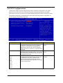
Frequency/Voltage Control
This item enables you to set the clock speed and system bus for your system.
The clock speed and system bus are determined by the kind of processor you have installed in the system.
Parameter
Description
Option
Auto Detect PCI/DIMM
Clk
When this item is enabled, BIOS will disable the
clock signal of free DIMM and PCI slots.
Enabled
Disabled
Spread Spectrum
If you enable spread spectrum, it can significantly
reduce the EMI (Elector Magnetic Interference)
generated by the system.
Disabled
Enabled
Chapter 2
42
Load Default Settings
You need to reload the BIOS default settings every time you make changes to your system hardware
configuration (such as memory size, CPU type, hard disk type, etc.); otherwise, BIOS will keep the
previous CMOS settings. Selecting this option displays the following dialog box:
Parameter
Load Default Settings
Description
Choosing Yes enables BIOS to automatically detect
the hardware changes that you have made in your
system. This option also allows you to restore the
default settings.
Option
N/A
Choosing No returns you to the main menu without
loading the default settings.
43
Chapter 2
Set Supervisor/User Password
Parameter
Set Supervisor Password
Description
To set a password:
1.
2.
3.
Set User Password
Chapter 2
At the prompt, type your password. Your
password can be up to 8 alphanumeric
characters. When you type the characters,
they appear as asterisks on the password
screen box.
After typing the password, press e.
Option
To disable the password,
press e when
prompted to enter the
password. The screen
displays a message
confirming that the
password has been
disabled.
At the next prompt, re-type your password
and press e again to confirm the new
password. After the password entry, the
screen automatically reverts to the main
screen.
To set a password:
1.
At the prompt, type your password. Your
password can be up to 8 alphanumeric
characters. When you type the characters,
they appear as asterisks on the password
screen box.
2.
After typing the password, press e.
3.
At the next prompt, re-type your password
and press e again to confirm the new
password. After the password entry, the
screen automatically reverts to the main
screen.
To disable the password,
press e when
prompted to enter the
password. The screen
displays a message
confirming that the
password has been
disabled.
44
Save & Exit Setup
Parameter
Save&Exit Setup
45
Description
Highlight this item and press <Enter> to save the
changes that you have made in the Setup Utility and
exit the Setup Utility. When the Save and Exit dialog
box appears, press <Y> to save and exit, or press
<N> to return to the main menu.
Option
N/A
Chapter 2
Exit Without Saving
Parameter
Exit Without Saving
Chapter 2
Description
Highlight this item and press <Enter> to discard any
changes that you have made in the Setup Utility and
exit the Setup Utility. When the Exit Without Saving
dialog box appears, press <Y> to discard changes
and exit, or press <N> to return to the main menu.
Option
N/A
46
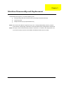
Chapter 3
Machine Disassembly and Replacement
To disassemble the computer, you need the following tools:
T
Wrist grounding strap and conductive mat for preventing electrostatic discharge.
T
A flat screw driver
T
Phillips screwdriver (may require different size).
NOTE: The screws for the different components vary in size. During the disassembly process, group the
screws with the corresponding components to avoid mismatches when putting back the components.
NOTE: The Aspire T130 mechanical housing is similar to AcerPower F1. Therefore, this chapter base on F1
to have minor rectify but the CPU and Heatsink are different between the two models.
Chapter 3
47
General Information
Before You Begin
Before proceeding with the disassenbly procedure, make sure that you do the following:
48
1.
Turn off the power to the system and all peripherals.
2.
Unplug the AC adapter and all power and signal cables from the system.
Chapter 3
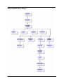
Disassemble Flow Chart
Chapter 3
49
Standard Disassembly Procedure
This section tells you how to disassemble the system when you need to perform system service. Please also
refer to the disassembly video, if available.
CAUTION: Before you proceed, make sure you have turned off the system and all peripherals connected to it.
NOTE: The Aspire T130 mechanical housing is similar to AcerPower F1. Therefore, this chapter base on F1
to have samll rectify but the CPU and Heatsink are different between the two models.
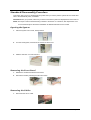
Opening the System
1.
Place the system unit on a flat, steady surface.
2.
Turn the housing back, and remove the screws as shown here.
3.
Slide the side door out. Then remove it.
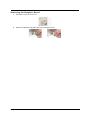
Removing the Front Panel
1.
Release the six latches behind the front bezel.
2.
Remove the bezel by following the instruction below.
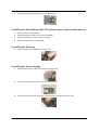
Removing the Cables
1.
50
Disconnect the Aux-In cable.
Chapter 3
2.
Disconnect the CD-In cable.
3.
Disconnect the floppy cable.
4.
Disconnect the IDE1 and IDE2 cable.
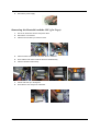
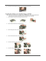
Removing the Modem card, CD-ROM, Floppy and HDD
NOTE: There have the hook lock on CD-ROM, floppy and HDD cage, in other words, please move a
little bit forward to release the lock then you can disassemble these parts smoothly.
1.
Detach the modem card.
2.
Disconnect the CD-ROM power, IDE and CD-In cables.
3.
Disconnect the floppy cable and power cable.
4.
Disconnect the HDD power cable and IDE cable.
Chapter 3
51
5.
Press the latch and remove the CD-ROM drive.
6.
Press the latch and remove the floppy drive.
7.
Press the latch again to release the hard disk module.
8.
Detach the HDD from the bracket.
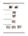
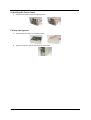
Removing the Power Supply
52
1.
Remove the main ATX power connector as shown here.
2.
Remove the Pentium 4(ATX-12V) power connector as shown here.
3.
Remove the four screws as shown here.
Chapter 3
4.
Remove the power supply.
Removing the Heatsink and the CPU ( for T130)
1.
First of all, disconnect the CPU fan power cable.
2.
Remove the 4 screws first.
3.
Take the CPU fan after you remove screws.
4.
Press the latch outward with a flat screw driver to release it.
5.
Then hold the both sides to take the latch and heatsink away.
6.
Take the retention module away.
7.
Pull the CPU bar up to 90 degrees.
8.
Then take the CPU away from mainboard.
Chapter 3
53
Removing the Memory
1.
Pop out the memory and remove it as shown here.
Removing the Mainboard
1.
Remove the six screw as shown here.
2.
Remove the motherboard as shown here.
Removing the Power Button
1.
Remove the power button as shown here.
Removing the LED Module
1.
54
Remove the LED module by following the instructions here.
Chapter 3
Removing the Daughter Board
1.
Remove the screw as shown here.
2.
Detach the USB cable and audio cable from the daughter board.
Chapter 3
55
Standard Reassembly Procedure
This section tells you how to reassemble the system when you need to perform system service. Please also
refer to the assembly video, if available.
Installing the Daughter Board
1.
Connect the audio cable and USB cables to the daughter board.
2.
Fasten the daughter board with one screw as shown here.
Installing the LED Module
1.
Install the LED module by following the instructions here.
Installing the Power Button
1.
Attach the power button as shown here.
Installing the Mainboard
1.
56
Put the motherboard to the original position as shown here.
Chapter 3
2.
Secure the motherboard with the six screw as shown here.
Installing the Heatsink and the CPU (please refer to disassemble photos)
1.
Place the CPU to the CPU socket.
2.
Place the rentention module next to previous installing.
3.
Place the heatsink then hook the latch to the tabs.
4.
Then place the CPU fan on the heatsink.
Installing the Memory
1.
Insert the memory to the DIMM slot as shown here.
Installing the Power Supply
1.
Place the power supply to the original position as shown here.
2.
Secure the power supply with the four screws as shown here.
3.
Connect the Pentium 4(ATX-12V) power connector to the motherboard as shown here.
Chapter 3
57
4.
Connect the main ATX power connector to the motherboard as shown here.
Installing the Modem card, CD-ROM, Floppy and HDD
NOTE: There have the hook lock on CD-ROM, floppy and HDD cage, in other words, please move a
little bit forward to release the lock then you can install these parts smoothly.
58
1.
Insert the HDD to the bracket by following the instructions here.
2.
Place the HDD module back to the original position.
3.
Place the floppy drive back to the original position.
4.
Place the CD-ROM drive back to the original position.
5.
Connect the HDD power cable and IDE cable.
6.
Connect the floppy cable and power cable.
Chapter 3
7.
Connect the CD-ROM power, IDE and CD-In cables.
8.
Place the modem card back to one PCI slot. Then secure the modem card with the screw.
Installing the Cables
1.
Connect the IDE1 and IDE2 cable to the motherboard.
2.
Connect the floppy cable to the motherboard.
3.
Connect the CD-In cable to the motherboard.
4.
Connect the Aux-In cable to the motherboard.
Chapter 3
59
Installing the Front Panel
1.
Place the front bezel back to the original position.
Closing the System
60
1.
Place the side door back to the original position.
2.
Secure the side door with the two screws as shown here.
Chapter 3
Chapter 4
Troubleshooting
This chapter provides troubleshooting information for the Aspire T130:
Chapter 4
T
Power-On Self-Test (POST)
T
Index of Error Messages
T
Index of Error Codes and Error Beeps
T
Index of Error Symptoms
T
Undetermined Problems
61
Power-On Self-Test (POST)
Each time you turn on the system, the Power-on Self Test (POST) is initiated. Several items are tested during
POST, but is for the most part transparent to the user.
The Power-On Self Test (POST) is a BIOS procedure that boots the system, initializes and diagnoses the
system components, and controls the operation of the power-on password option. If POST discovers errors in
system operations at power-on, it displays error messages on screen, generates a check point code at port
80h or even halts the system if the error is fatal.
The main components on the main board that must be diagnosed and/or initialized by POST to ensure system
functionality are as follows:
62
T
Microprocessor with built-in numeric co-processor and cache memory subsystem
T
Direct Memory Access (DMA) controller
T
Interrupt system
T
Three programmable timers
T
ROM subsystem
T
RAM subsystem
T
RTC RAM subsystem and real time clock/calendar with battery backup
T
Onboard serial interface controller
T
Onboard parallel interface controller
T
Embedded hard disk interface and one diskette drive interface
T
Keyboard and auxiliary device controllers
T
I/O ports
T
PS/2-compatible mouse port
T
PS/2-compatible keyboard port
T
Serial ports
T
Parallel ports
T
USB port
Chapter 4
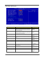
POST Check Points
When POST executes a task, it uses a series of preset numbers called check point to be latched at port 80h,
indicating the stages it is currently running. This latch can be read and shown on a debug board.
The following table describes the Acer common tasks carried out by POST. A unique check point number
represents each task.
Checkpoint
Description
CFh
Test CMOS R/W functionality
C0h
Early chipset initialization:
•
•
•
C1h
Detect memory
•
•
Chapter 4
Disable shadow RAM
Disable L2 Cache (socket 7 or below)
Program basic chipset registers
Auto-detection of DRAM size, type and ECC.
Auto-detection of L2 cache (socket 7 or below)
C3h
Expand compressed BIOS code to DRAM
C5h
Call chipset hook to copy BIOS back to E000 & F000
shadow RAM
0h1
Expand the Xgroup codes locating in physical address
1000:0
02h
Reserved
03h
Initial Superio_Early_Init switch
04h
Reserved
05h
1. Blank out screen
2. Clear CMOS error flag
06h
Reserved
07h
1. Clear 8042 interface
2. Initialize 8042 self-test
08h
1. Test special keyboard controller for Winbond 977 series
Super I/O chips
2. Enable keyboard interface
09h
Reserved
0Ah
1. Disable PS/2 mouse interface (optional)
2. Auto detect ports for keyboard & mouse followed by a
port & interface swap (optional)
3. Reset keyboard for Winbond 977 series Super I/O
chips
0Bh
Reserved
0Ch
Reserved
0Dh
Reserved
0Eh
Test F000h segment shadow to see whether it is R/W-able
or not. If test fails. keep beeping the speaker.
0Fh
Reserved
10h
Auto detect flash type to load appropriate flash R/W codes
into the run time area in F000 for ESCD & DMI support.
63
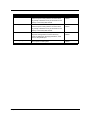
Checkpoint
Description
11h
Reserved
12h
Use walking 1’s algorithm to check out interface in CMOS
circuitry. Also set real-time clock power status, and then
check for override.
13h
Reserved
14h
Program chipset default values into chipset. Chipset
default values are MODBINable by OEM customers.
15h
Reserved
16h
Initial onboard clock generator if
Early_Init_Onboard_Generator is defined. See also POST
26h.
17h
Reserved
18h
Detect CPU information including brand, SMI type (Cyrix or
Intel) and CPU level (586 or 686).
19h
Reserved
1Ah
Reserved
1Bh
Initial interrupts vector table. If no special specified, all H/
W interrupts are directed to SPURIOUS_INT_HDLR & S/
W interrupts to SPURIOUS_soft_HDLR.
1Ch
Reserved
1Dh
Initial EARLY_PM_INIT switch
1Eh
Reserved
1Fh
Load keyboard matrix (notebook platform)
20h
Reserved
21h
HPM Initialization (notebook platform)
22h
Reserved
23h
1. Check validity of RTC value:
e.g. a value of 5Ah is an invalid value for RTC minute.
2. Load CMOS settings into BIOS stack. If Smos checksum fails, use default value instead.
24h
Prepare BIOS resource map for PCI & PnP use. If ESCD
is valid, take into consideration of the ESCD’s legacy information.
25h
Early PCI Initialization:
•
•
•
64
Enumerate PCI bus number
Assign memory & I/O resource
Search for a valid VGA device & VGA BIOS, and put it
into C000:0
26h
1. If Early_Init_Onboard_Generator is not defined
Onboard clock generator initialization. Disable respective clock resource to empty PCI & DIMM slots.
2. Init onboard PWM
3. Init onboard H/W monitor devices
27h
Initialize INT 09 buffer
28h
Reserved
Chapter 4
Checkpoint
Chapter 4
Description
29h
1. Program CPU internal MTRR (P6 & PII) for 0-640K
memory address.
2. Initialize the APIC for Pentium class CPU
3. Program early chipset according to CMOS setup.
Example: onboard IDE controller.
4. Measure CPU speed.
2Ah
Reserved
2Bh
Invoke Video BIOS
2Ch
Reserved
2Dh
1. Initialize double-byte language font (Optional)
2. Put information on screen display, including Award title,
CPU type, CPU speed, full screen logo.
2Eh
Reserved
2Fh
Rederved
30h
Reserved
31h
Reserved
32h
Reserved
33h
Reset keyboard if Early_Reset_KB is defined e.g. Winbond 977 series Super I/O chips. See also POST 63h
34h
Reserved
35h
Test DMA Channel 0
36h
Reserved
37h
Test DMA Channel 1
38h
Reserved
39h
Test DMA page registers
3Ah
Reserved
3Bh
Reserved
3Ch
Test 8254
3Dh
Reserved
3Eh
Test 8259 interrupt mask bits for channel 1
3Fh
Reserved
40h
Test 8259 interrupt mask bits for channel 2
41h
Reserved
42h
Reserved
43h
Test 8259 functionality
44h
Reserved
45h
Reserved
46h
Reserved
47h
Initialize EISA slot
48h
Reserved
49h
1. Calculate total memory by testing the last double word
of each 64K page.
2. Program write allocation for AMD K5 CPU.
4Ah
Reserved
4Bh
Reserved
65
Checkpoint
Description
4Ch
Reserved
4Dh
Reserved
4Eh
1. Program MTRR of M1 CPU
2. Initialize L2 cache for P6 class CPU & program CPU
with proper cacheable range.
3. Initialize the APIC for P6 class CPU.
4. On MP platform, adjust the cacheable range to smaller
one in case the cacheable ranges between each CPU
are not identical.
4Fh
Reserved
50h
Initialize USB Keyboard & Mouse
51h
Reserved
52h
Test all memory (clear all extended memory to 0)
53h
Clear password according to H/W jumper (Optional)
54h
Reserved
55h
Display number of processors (multi-processor platform)
56h
Reserved
57h
1. Display PnP logo
2. Early ISA PnP initialization - Assign CSN to every ISA
PnP device
58h
Reserved
59h
Initialize the combined Trend Anti-Virus code
5Ah
Reserved
5Bh
(Optional Feature)
Show message for entering AWDFLASH.EXE from FDD
(optional)
5Ch
Reserved
5Dh
1. Initialize Init_Onboard_Super_IO
2. Initialize Init_Onboard_AUDIO
5Eh
Reserved
5Fh
Reserved
60h
Okay to enter Setup utility; i.e. not until this POST stage
can users enter the CMOS setup utility.
61h
Reserved
62h
Reserved
63h
Reset keyboard if Early_Reset_KB is not defined.
64h
Reserved
65h
Initialize PS/2 Mouse
66h
Reserved
67h
Prepare memory size information for function call:
INT 15h ax=E820h
66
68h
Reserved
69h
Turn on L2 cache
6Ah
Reserved
Chapter 4
Checkpoint
Description
6Bh
Program chipset registers according to items described in
Setup & Auto-configuration table
6Ch
Reserved
6Dh
1. Assign resources to all ISA PnP devices.
2. Auto assign ports to onboard COM ports if the corresponding item in Setup is set to “Auto”.
6Eh
Reserved
6Fh
1. Initialize floppy controller
2. Set up floppy related fields in 40:hardware
70h
Reserved
71h
Reserved
72h
Reserved
73h
Reserved
74h
Reserved
75h
Detech &install all IDE device: HDD, LS120, ZIP,
CDROM...
76h
(Optional feature)
Enter AWDFLASH.EXE if:
- AWDFLASH.EXE is found in floppy drive.
- ALT+F2 is prrssed.
77h
Detect serial ports & parallel ports
78h
Reserved
79h
Reserved
7Ah
Detect & install co-processor
7Bh
Reserved
7Ch
Init HDD write protect
7Dh
Reserved
7Eh
Reserved
7Fh
Switch back to text mode if full screen logo is supported.
- If errors occur, report errors & wait for keys
- If no errors occur or F1 key is pressed to continue:
Clear EPA or customization logo.
Chapter 4
80h
Reserved
81h
Reserved
82h
1. Call chipset power management hook.
2. Recover the text fond used by EPA logo (not for full
screen logo).
3. If password is set, ask for password.
83h
Save all data in stack back to CMOS
84h
Initialize ISA PnP boot devices
85h
1. USB final initialization
2. Switch screen back to text mode
86h
Reserved
87h
NET PC: Build SYSID structure
67
Checkpoint
68
Description
88h
Reserved
89h
1. Assign IRQs to PCI devices.
2. Set up ACPI table at top of the memory.
8Ah
Reserved
8Bh
1. Invoke all ISA adapter ROMs
2. Invoke all PCI ROMs (except VGA)
8Ch
Reserved
8Dh
1. Enable/Disable Parity Check according to CMOS
setup.
2. APM Initialization
8Eh
Reserved
8Fh
Clear noise if IRQs
90h
Reserved
91h
Reserved
92h
Reserved
93h
Read HDD boot sector information for Trend Anti-Virus
code
94h
1.
2.
3.
4.
5.
6.
7.
8.
Enable L2 cache
Program Daylight Saving
Program boot up speed
Chipset final initialization
Power management final initialization
Clear screen & dispaly summary table
Program K6 write allocation
Program P6 class write combining
95h
Update keyboard LED & typematic rate
96h
1.
2.
3.
4.
5.
FFh
Boot attempt (INT 19h)
Build MP table
Build & update ESCD
Set CMOS century to 20h or 19h
Load CMOS time into DOS timer tick
Build MSIRQ routing table
Chapter 4
POST Error Messages List
If you cannot run the diagnostics program tests but did receive a POST error message, use “POST Error
Messages List” to diagnose system problems. If you did not receive any error message, look for a description
of your error symptoms in “Error Sympton List”.
NOTE: When you have deemed it necessary to replace an FRU, and have done so, you must run a total
system check to ensure that no other activity has been affected by the change. This system check can
be done through the diagnostics program.
NOTE: Check all power supply voltages, switch, and jumper settings before you replace the main board. Also
check the power supply voltages if you have a “system no-power” condition.
NOTE: To diagnose a problem, first find the BIOS error messages in the left column. If directed to a check
procedure, replace the FRU indicated in the check procedure. If no check procedure is indicated, the
first Action/FRU listed in right column is the most likely cause.
BIOS Messages
Action/FRU
I/O Parity Error
1. System board
CPU Clock Mismatch
1. Enter BIOS Setup and load the default settings.
2. Ensure BIOS setting for processor is set
correctly.
Real Time Clock Error
CMOS Battery Bad
CMOS Checksum Error
1. Enter BIOS Setup and load the default settings.
2. RTC Battery.
3. System Board.
Equipment Configuration Error
1. Ensure the system configuration set in BIOS
Setup is correct.
2. Enter BIOS Setup and load the default settings.
3. RTC battery.
4. System board.
System Management Memory Bad
Memory Error at MMMM:SSSS:OOOOh
1. Insert the memory modules in the DIMM sockets
properly, then reboot the system.
2. Memory module.
3. System board.
RAM Parity Error
1. Enter BIOS Setup to disable parity check.
2. Memory module
3. System board
PS/2 Keyboard Error or Keyboard Not
Connected
PS/2 Keyboard Interface Error
PS/2 Keyboard Locked
1.
2.
3.
4.
5.
Onboard xxx... Conflict(s)
1. Enter BIOS Setup and load the default settings.
2. Remove all adapter cards that are NOT factoryinstalled, then reboot the system.
Floppy Disk Controller Error
Floppy Drive A Error
Floppy Drive B Error
1. Diskette drive cable/connection.
2. Diskette drive.
3. System board
On Board Parallel Port Conflict(s)
On Board Serial Port 1 Conflict(s)
On Board Serial Port 2 Conflict(s)
1. Enter BIOS Setup and load the default settings.
2. Remove all adapter cards that are NOT factoryinstalled, then reboot the system.
Chapter 4
Re-connect PS/2 keyboard and mouse.
Enter BIOS Setup and load the default settings.
PS/2 keyboard
PS/2 mouse
System board
69
BIOS Messages
70
Action/FRU
Floppy Drive(s) Write Protected
Hard Disk Drive(s) Write Protected
1. Ensure that the diskette drive is not set to [Write
Protected] in the Security Options in BIOS
Setup.
2. Load default settings in Setup.
IDE Drive 0 Error
IDE Drive 1 Error
IDE Drive 2 Error
IDE Drive 3 Error
1.
2.
3.
4.
5.
IRQ Setting Error
Expansion ROM Allocation Fail
I/O Resource Conflict(s)
Memory Resource Conflict(s)
1. Load default settings in Setup.
2. Enter BIOS Setup and set the Reset
Resource Assignments of the PnP/PCI
Options to Yes, then reboot the system.
3. Remove all adapter cards that are NOT factoryinstalled, then reboot the system
PCI Device Error
1. Load default settings in Setup.
2. Enter BIOS Setup and set the Reset
Resource Assignments of the PnP/PCI
Options to Yes, then reboot the system.
3. Remove all adapter cards that are NOT factoryinstalled, then reboot the system.
PS/2 Pointing Device Interface Error
PS/2 Pointing Device Error
1.
2.
3.
4.
5.
Enter BIOS Setup and load the default settings.
Check IDE drive jumper.
IDE hard disk drive power.
IDE hard disk drive cable/connection.
IDE hard disk drive.
Re-connect PS/2 keyboard and mouse.
Enter BIOS Setup and load the default settings.
PS/2 mouse
PS/2 keyboard
System board
DMI Table Was Destroyed
1. Flash BIOS
Press “DEL” key to enter Setup or F1 key to
continue
1. Press DEL to enter Setup and reconfigure the
system.
Press ESC to turn off NMI, or any key to reboot
1. Press ESC to reject NMI error or press any other
key to reboot the system.
Insert system diskette and press ENTER key to
reboot
1. Insert a bootable disk into the floppy disk drive
or remove this disk if a hard disk is installed.
Chapter 4
Error Symptoms List
NOTE: To diagnose a problem, first find the error symptom in the left column. If directed to a check procedure,
replace the FRU indicated in the check procedure. If no check procedure is indicated, the first Action/
FRU listed in right column is the most likely cause
.
Error Symptom
Action/FRU
Processor / Processor Fan
NOTE: Normally, the processor fan should be operative, and the processor clock setting should be
exactly set to match its speed requirement before diagnosing any processor problems.
Processor fan does not run but power
supply fan runs.
1. Ensure the system is not in power saving mode. See
“Power Management” in chapter 2.
2. With the system power on, measure the voltage of
processor fan connector. Its reading should be +12Vdc.
3. System board.
Processor test failed.
1. Processor
2. System board
System Board and Memory
NOTE: Ensure the memory modules are installed properly and the contact leads are clean before
diagnosing any system problems.
Memory test failed.
1. See "Memory"
2. System board
Incorrect memory size shown or
repeated during POST.
1. Insert the memory modules in the DIMM sockets properly,
then reboot the system.
2. Memory module.
3. System board.
System works but fails to enter power
saving mode when the Power
Management Mode is set to Enabled,
and power saving timer set in BIOS has
elapsed.
1. Enter BIOS Setup and load default settings.
In Windows 98, check settings in Power Management
Property of Control Panel.
2. Reload software from Recovery CD.
System hangs before system boot.
1. See "Index of Symptoms"
2. See "Undetermined Problems"
System hangs after system boot.
1. Execute a system test and set it to stop at “Halt on Error”
to see the potential cause of the problem.
2. See “Undetermined Problems”.
Blinking cursor only; system does not
work.
1.
2.
3.
4.
Diskette/IDE drive connection/cables
Diskette/IDE disk drives
See “Undetermined Problems”.
System board
Diskette Drive
NOTE: Ensure the diskette drive is configured correctly in BIOS Setup and its read/write head is
clean before diagnosing any diskette drive problems.
Media and drive are mismatched.
Chapter 4
1. Ensure the diskette drive is configured correctly in the
Disk Drives of BIOS Setup.
2. Ensure the diskette drive is correctly formatted.
3. Diskette drive connection/cable
4. Diskette drive
5. System board
71
Error Symptom
Action/FRU
Diskette drive does not work.
1. Ensure the diskette drive is not set to None in the Disk
Drives of BIOS Setup.
2. Diskette drive power
3. Diskette drive connection/cable
4. Diskette drive
5. System board
Diskette drive read/write error.
1. Diskette.
2. Ensure the diskette drive is not set to Write protect
in the Security Options of BIOS Setup.
3. Diskette drive cable.
4. Diskette drive.
5. System board.
Diskette drive LED comes on for more
than 2 minutes when reading data.
1.
2.
3.
4.
Diskette
Diskette drive connection/cable
Diskette drive
System board
Diskette drive LED fails to light, and the
drive is unable to access for more than 2
minutes.
1.
2.
3.
4.
5.
Diskette
Diskette drive power
Diskette drive connection/cable
Diskette drive
System board
Diskette drive test failed.
1.
2.
3.
4.
Diskette
Diskette drive
Diskette drive cable
System board
Hard Disk Drive
NOTE: Ensure hard disk drive is configured correctly in BIOS Setup, cable/jumper are set correctly
before diagnosing any hard disk drive problems.
Hard disk drive test failed.
1.
2.
3.
4.
Enter BIOS Setup and Load default settings.
Hard disk drive cable.
Hard disk drive.
System board.
Hard disk drive cannot format
completely.
1.
2.
3.
4.
Enter BIOS Setup and Load default settings.
Hard disk drive cable.
Hard disk drive.
System board.
Hard disk drive has write error.
1. Enter BIOS Setup and Load default settings.
2. Hard disk drive.
Hard disk drive LED fails to light, but
system operates normally.
1. With the system power on, measure the voltage of hard
disk LED connector.
2. Hard drive LED cable.
CD/DVD-ROM Drive
NOTE: Ensure CD/DVD-ROM drive is configured correctly in BIOS Setup, cable/jumper are set
correctly and its laser beam is clean before diagnosing any CD/DVD-ROM drive problems.
CD/DVD-ROM drive LED doesn't come
on but works normally.
72
1. CD/DVD-ROM drive
Chapter 4
Error Symptom
CD/DVD-ROM drive LED flashes for
more than 30 seconds before LED
shutting off.
Action/FRU
1. CD/DVD-ROM may have dirt or foreign material on it.
Check with a known good disc.
2. CD/DVD-ROM is not inserted properly.
3. CD/DVD-ROM is damaged.
Software asks to reinstall disc.
Software displays a reading CD/DVD
error.
CD/DVD-ROM drive cannot load or eject
when the system is turned on and its
eject button is pressed and held.
1. Disconnect all cables from CD/DVD-ROM drive except
power cable, then press eject button to try to unload the
disk.
2. CD/DVD-ROM drive power.
3. CD/DVD-ROM drive
CD/DVD-ROM drive does not read and
there are no messages are displayed.
1. CD may have dirt or foreign material on it. Check with a
known good disc.
2. Ensure the CD/DVD-ROM driver is installed properly.
3. CD/DVD-ROM drive.
CD/DVD-ROM drive can play audio CD
but no sound output.
1. Ensure the headphone jack of the CD/DVD-ROM has an
output.
2. Turn up the sound volume.
3. Speaker power/connection/cable.
4. CD/DVD-ROM drive.
Real-Time Clock
Real-time clock is inaccurate.
1. Ensure the information in the Date and Time of BIOS
Setup is set correctly.
2. RTC battery.
3. System board
Audio software program invokes but no
sound comes from speakers.
1. Speaker power/connection/cable.
Audio
Modem
Modem ring cannot wake up system
from suspend mode.
1. Ensure the Modem Ring Indicator in BIOS Setup or
Power Management is set to Enabled.
2. If PCI modem card is used, reinsert the modem card to
PCI slot firmly or replace the modem card.
3. If ISA modem card is used, ensure the modem ring-in
cable from the modem card to system board is connected
properly.
4. In Win 98, ensure the telephone application is configured
correctly for your modem and set to receive messages
and/or fax.
Data/fax modem software program
invokes but cannot receive/send data/
fax
1. Ensure the modem card is installed properly.
Fax/voice modem software program
invokes but has no sound output. (Data
files are received normally; voice from
modem cannot be produced, but system
sound feature works normally.)
1. Ensure the modem voice-in cable from modem adapter
card to system board
Video and Monitor
Video memory test failed.
Video adapter failed.
Chapter 4
1. Remove all non-factory-installed cards.
2. Load default settings (if screen is readable).
3. System board
73
Error Symptom
74
Action/FRU
Display problem:
- Incorrect colors
No high intensity
Missing, broken, or incorrect characters
Blank monitor(dark)
Blank monitor(bright)
Distorted image
Unreadable monitor
Other monitor problems
1.
2.
3.
4.
Display changing colors.
1. Monitor signal connection/cable
2. Monitor
3. System board
Display problem not listed above
(including blank or illegible monitor).
1. “Monitor".
2. Load default settings (if screen is readable).
3. System board
Monitor signal connection/cable.
Monitor
Video adapter card
System board
Chapter 4
Error Symptom
Action/FRU
Parallel/Serial Ports
Execute “Load BIOS Default Settings” in BIOS Setup to confirm ports presence before diagnosing any
parallel/serial ports problems.
Serial or parallel port loop-back test
failed.
1. Make sure that the LPT# or COM# you test is the same
as the setting in BIOS Setup.
2. Loop-back.
3. System board.
Printing failed.
1. Ensure the printer driver is properly installed. Refer to the
printer service manual.
2. Printer.
3. Printer cable.
4. System board.
Printer problems.
1. Refer to the service manual for the printer.
Keyboard
Some or all keys on keyboard do not
work.
1. Keyboard
Power Supply
Pressing power switch does not turn off
system. (Only unplugging the power
cord from electrical outlet can turn off the
system.)
1. Ensure the Power Switch < 4 sec. in BIOS Setup of
Power Management is not set to Suspend.
2. Power switch cable assembly
Pressing power switch does not turn on
the system.
1. Ensure the power override switch (situated at the back of
the machine, just above the connector for the power
cable) is not set to OFF.
2. Power switch cable assembly.
Executing software shutdown from
Windows98 Start menu does not turn off
the system. (Only pressing power switch
can turn off the system).
1. Load default settings.
2. Reload software from Recovery CD.
No system power, or power supply fan is
not running.
1. Power Supply
2. System Board
Other Problems
Any other problems.
Chapter 4
1. Undetermined Problems
75
Chapter 5
Jumper and Connector Information
Before setting jumpers
Use the mainboard jumpers to set system configuration options. Jumpers with more than one pin are
numbered. When settting the jumpers, ensure that the jumper caps are placed on the correct pins.
Illustration
Description
The illustrations below show a 2-pin jumper. When the
jumper cap is placed on both pins, the jumper is SHORT.
If you remove the jumper cap, or place the jumper cap on
just one pin, the jumper is OPEN.
Short
Open
This illustration shows a 3-pin jumper. Pins 1 and 2 are
SHORT.
1 2
3
Chapter 5
76
Header Definition
Name
77
Connector Type
Description
CPUFAN1
AMP640456-3
CPU FAN
CASFAN1
AMP640456-3
Chassis Fan
PWRFAN1
AMP640456-3
Power Fan
COM1
CONN-9P2R-90M
Serial Port 1
USB1394A2
USB-DUAL/1394
1394 and USB connector
USB1
H5*2
USB Header
USB2
H5*2
USB Header
USB3
H5*2
USB Header
FDD1
H17*2LW
Floppy connector
IDE1
H20*2LW
HDD primary connector
IDE2
H20*2LW
HDD secondary connector
PANEL1
H5*2
PWR_SW/RST/HDD_LED/PWR_LED
AUDIO1
H5*2
Audio header for front side connector
SPDIF
H3*1
SPDIF Header
ATX1
PW_20P2R
AXT power connector
ATX12V
AXT_PWR_CON4A
ATX 12V power connector
Chapter 5
Jumper and Connector Settings
The following illustration shows the location of the mainboard jumpers. Pin 1 is labeled.
Jumper
JP1
JP3
Type
3-pin
3-pin
Description
Setting(default)
Clear CMOS
Use this jumper to clear the
contents of the CMOS memory.
You may need to clear the
CMOS memory if the settings in
the Setup Utility are incorrect
and prevent your mainboard
1-2:Normal
2-3:Clear CMOS
BIOS Protect
1-2: Disable
2-3:Enable
Illustrator
JP1
JP2
Chapter 5
1
1
78
ATX 12V: ATX 12V Power Connector
Pin
Signal Name
1
+12V
2
+12V
3
Ground
4
Ground
ATX1: ATX 20-pin Power Connector
Pin
79
Signal Name
Pin
Signal Name
1
+3.3V
11
+3.3V
2
+3.3V
12
-12V
3
Ground
13
Ground
4
+5V
14
PS ON#
5
Ground
15
Ground
6
+5V
16
Ground
7
Ground
17
Ground
8
PWRGD
18
-5V
9
+5VSB
19
+5V
10
+12V
20
+5V
Chapter 5
CPUFAN1/CASFAN1/PWRFAN1: FAN Power Connector
Pin
Signal Name
Function
1
GND
System Ground
2
+12V
Power +12V
3
Sense
Sensor
1
2
3
COM1
Pin
1
2
6
3
7
5
4
8
9
Signal Name
1
DCD
2
RxD
3
TxD
4
DTR
5
Ground
6
DSR
7
RTS
8
CTS
9
RI
LPT
Pin
Front Side View
Pinout Top-View
Chapter 5
Signal Name
Pin
Signal Name
1
STROBE
13
SLCT
2
PD0
14
ALF
3
PD1
15
ERROR
4
PD2
16
INIT
5
PD3
17
SLCTIN
6
PD4
18
GROUND
7
PD5
19
GROUND
8
PD6
20
GROUND
9
PD7
21
GROUND
10
ACK
22
GROUND
11
BUSY
23
GROUND
12
PE
24
GROUND
25
GROUND
80
PSKBM1
PS/2 Keyboard
16
15
3
PS/2 Mouse
14
13
5
12
11
13
PS/2 Mouse
1
KBDATA
11
MDATA
2
NC
12
NC
3
GROUND
13
GROUND
4
VCC
14
VCC
5
KBCLK
15
MCLK
6
NC
16
NC
15
6
5
PS/2 Keyboard
4
3
2
1
USBLAN1
Pin
L7
L8
G8
L16
L15
G9
L18
L1
L2
L10
L9
VCC
G3
L17
81
U5
U8
U1
U4
G4
VCC
G1
G5
G10
G6
G2
G7
Signal Name
Pin
Signal Name
U1
VCC
G7
HOLE_LAN
U2
-DATA0
G8
HOLE_LAN
U3
+DATA0
G9
HOLE_LAN
U4
GND
G10
HOLE_LAN
U5
VCC
L1
TX+
U6
-DATA1
L2
TX-
U7
+DATA1
L3
RX+
U8
GND
L4
NC
G1
HOLE_USB
L5
NC
G2
HOLE_USB
L6
RX-
G3
HOLE_USB
L7
NC
G4
HOLE_USB
L8
NC
G5
HOLE_LAN
L17
PLED0
G6
HOLE_LAN
L18
PLED1
Chapter 5
USB1, USB3
Pin
Signal Name
Pin
Signal Name
1
USBPWR0
6
USBPWR1
2
USB0-
7
USB1-
USB0+
8
USB1+
1
6
3
2
7
4
NC
9
KEY
3
8
5
GND
10
GND
4
9
5
10
FDD1
2
4
6
8
10
12
14
16
18
20
22
24
26
28
30
32
34
1
3
5
7
9
11
13
15
17
19
21
23
25
27
29
31
33
Pin
Signal Name
Pin
Signal Name
1
GROUND
2
DRVDEN0
3
GROUND
4
HDL-
5
KEYPIN
6
DS3-
7
GROUND
8
INDEX-
9
GROUND
10
MTR0-
11
GROUND
12
DS0-
13
GROUND
14
DS1-
15
GROUND
16
MTR1-
17
GROUND
18
DIR-
19
GROUND
20
STEP-
21
GROUND
22
WDATA
23
GROUND
24
WGATE-
25
GROUND
26
TRK0-
27
GROUND
28
WP-
29
GROUND
30
RDATA
31
GROUND
32
HDSEL-
33
GROUND
34
DSKCHG-
Chapter 5
82
IDE1, IDE2
2
4
6
8
10
12
14
16
18
20
22
24
26
28
30
32
34
36
38
40
1
3
5
7
9
11
13
15
17
19
21
23
25
27
29
31
33
35
37
39
Pin
Signal Name
Pin
Signal Name
1
RESET-
2
GROUND
3
DD7
4
DD8
5
DD6
6
DD9
7
DD5
8
DD10
9
DD4
10
DD11
11
DD3
12
DD12
13
DD2
14
DD13
15
DD1
16
DD14
17
DD0
18
DD15
19
GROUND
20
KEYPIN
21
DMARQ
22
GROUND
23
DIOW-
24
GROUND
25
DIOR-
26
GROUND
27
IORDY
28
PSYNC:CSEL
29
DMACK-
30
GROUND
31
INTRQ
32
IOCS16-
33
DA1
34
PDIAG-
35
DA0
36
DA2
37
CS1FX-
38
CS3FX-
39
DASP-
40
GROUND
COM2
Pin
83
Signal Name
Pin
Signal Name
1
NDCDB
2
NSINB
3
NSOUTB
4
NDTRB
1
2
5
GND
6
NDSRB
3
4
7
NRTSB
8
NCTSB
5
6
9
NRIB
10
KEY
7
8
9
10
Chapter 5
PANEL1
Pin
Signal Name
1
HD_LED_P
Pin
2
Signal Name
PWR_SLP
3
HD_LED_N
4
PWR_SLP
1
2
5
RST_SW_N
6
PWR_SW_P
3
4
5
7
RST_SW_P
8
PWR_SW_N
6
7
8
9
RSVD
10
KEY
9
10
1394A_J2
Pin
Signal Name
1
HD_LED_P
Pin
2
Signal Name
PWR_SLP
3
HD_LED_N
4
PWR_SLP
1
2
5
RST_SW_N
6
PWR_SW_P
3
4
7
RST_SW_P
8
PWR_SW_N
5
6
9
RSVD
10
KEY
7
8
9
10
AUDIO1
Pin
Chapter 5
1
2
3
4
5
6
7
8
9
10
Signal Name
Pin
Signal Name
1
AUD_MIC
2
AUD_GND
3
MIC_BIAS
4
AUD_VCC
5
AUD_F_R
6
AUD_RET_R
7
REVD
8
KEY
9
AUD_F_L
10
AUD_RET_L
84
Front Panel Connector
The front panel connector (PANEL1) provides a standard set of switch and LED connectors commonly
found on ATX or micro-ATX cases. Refer to the table below for information:
Pin
85
Singal Name
Function
Pin
Signal Name
Function
1
HDDLED
Hard disk
LED(positive)
2
SUS LED
Suspend LED
[dual color or
single color(+)]
3
HDDLED
Hard disk active
LED (negative)
4
SUS LED
Suspend LED
[dual color or
single color(-)]
5
RST_SW_N
Reset Switch
6
PWR_SW_P
Power Switch
7
RST_SW_P
Reset Switch
8
PWR_SW_N
Power Switch
9
RSVD
Reserved
10
Key
No pin
11
GND
Ground
12
5VSB
13
GND
Ground
14
5VSB
Chapter 5
Chapter 6
FRU (Field Replaceable Unit) List
This chapter gives you the FRU (Field Replaceable Unit) listing in global configurations of
Aspire T130. Refer to this chapter whenever ordering for parts to repair or for RMA (Return
Merchandise Authorization).
NOTE: Please note WHEN ORDERING FRU PARTS, that you should check the most up-to-date information
available on your regional web or channel (http://aicsl.acer.com.tw/spl/, if you do not own a specific
account, you can still access the system with guest; guest). For whatever reasons a part number
change is made, it will not be noted in the printed Service Guide. For ACER-AUTHORIZED SERVICE
PROVIDERS, your Acer office may have a DIFFERENT part number code to those given in the FRU list
of this printed Service Guide. You MUST use the local FRU list provided by your regional Acer office to
order FRU parts for repair and service of customer machines.
NOTE: To scrap or to return the defective parts, you should follow the local government ordinance or
regulations on how best to dispose it, or follow the rules set by your regional Acer office on how to
return it.
Chapter 6
86
Aspire T130 Exploded Diagram
87
Chapter 6
Spare Parts
Category
Partname
Description
USB BOARD
Acer P/N
BOARD
USB/AUDIO DAUGHTER
BOARD FOXCONN
55.PSPVF.001
CABLES
IDE CD-ROM CABLE ATA66 CDROM DATA CABLE
40PIN
50.PSPVF.002
IDE FDD CABLE 34PIN
FDD DATA CABLE
50.PSPVF.003
AUDIO CABLE 8PIN 2CON
AUDIO CABLE
50.S03VF.001
FRONT INTERNAL USB
CABLE
USB CABLE
50.S03VF.002
FRONT BEZEL W/POWER BEZEL ASSY
BUTTON. 5.25”, 3.5” EMPTY
COVER, USB DOOR
60.S03VF.001
POWER BUTTON
POWER BUTTON (PAINTED)
42.S03VF.001
SIDE DOOR
BKT-DOOR (PAINTING)
60.S03VF.002
CHASSIS W/O I/O SHIELD
T120 SUB CASE ASSY(W/O IO
SHIELD)
60.S02VF.001
I/O SHIELD
I/O SHIELD ASSY
33.S02VA.001
LED MODULE
LED HOLDER ASSY
42.S02VF.001
SWITCH HOLDER ASSY
SWITCH HOLDER ASSY
42.S02VF.002
EMPTY COVER FOR 5.25”
DEVICE
5.25” FILLER PANEL
42.S03VF.004
HDD BRACKET
BKT-HDD
33.PSPVF.002
FILLER COVER FOR 3 1/2”
DEVICE
3.5” FILLER PANEL
42.S03VF.005
FOOT
STAND
RUBBER FOOT
RUBBER FOOT
47.S03VF.001
CD-ROM
DRIVE
CD-RW DRIVE 52X BTC
BCE 5224IM ACER COLOR
W/O ACER LOGO
CD-RW DRIVE 52X BTC BCE 5224IM
ACER COLOR W/O ACER LOGO
KR.52X0A.002
CD-RW DRIVE 52XR
24XRW 52XW LITE-ON
LTR-52246S BLACK W/O
ACER LOGO
CD-RW DRIVE 52XR 24XRW 52XW
LITE-ON LTR-52246S BLACK
KR.05201.001
CD-RW DRIVE 52X24X52X
LITE-ON LTR-52246S
BLACK
DRV, CD-RW,52X/24X/52X,LTR52246S,LITEON BLACK
KR.05201.001
DVD-ROM DRIVE 16X/40X
BTC BDV 316E ACER
COLOR W/O ACER LOGO
BLACK
DVD-ROM DRIVE 16X/40X BTC BDV
KV.0160A.002
316E ACER COLOR W/O ACER LOGO
BLACK
DVD-ROM DRIVE 16X
PIONEER DVD-121RD
BLACK W/O ACER LOGO
DRV,DVD-ROM 16X40X,DVD-121RD
PIONEER (BLACK)
KV.01605.003
DVD-ROM DRIVE 16X
PIONEER DVD-121RD
BLACK W/O ACER LOGO
DRV,DVD-ROM 16X40X,DVD-121RD
PIONEER (BLACK)
KV.01605.003
COMBO DRIVE 48X HLDS
GCC-4480B BLACK W/O
ACER LOGO
DRV, COMBO, 48X, GCC-4480B,
HLDS BLACK
KO.0480A.001
CASE/
COVER/
BRACKET
ASSEMBLY
DVD-ROM
DRIVE
COMBO
DRIVE
Chapter 6
88
Category
Partname
Description
Acer P/N
DVD-RW
DRIVE
4X DVD SUPERMULTI
PLUS(BLACK) HLDS GSA4040B BLACK W/O ACER
LOGO
DVD SUPER MULTI DVD+/- RW DVD- KU.0040D.007
RAM 4X/2.4X/2X/2X HLDS GAS-4040B
BLACK
FANSINK
FAN SINK FOR ATHLON 64
FAN SINK FOR ATHLON 64
HI.1720C.001
FAN
SYSTEM FAN
SYSTEM FAN
HI.9830C.001
CUP/
PROCESS
OR
ATHLON 64 3200+
(CLAWHANMMER)
2.0GHZ, 800MHz, 1MB L2
KC.A3202.064
ATHLON 64 3000+
(CLAWHAMMER)
1.8GHz, 800MHz, 1MB L2
KC.A3002.064
FDD/
FLOPPY
DISK
DRIVE
FDD 1.44MB PANASONIC
JU-256A048P BLACK
FDD, PANASONIC,JU-256A048P
BLACK
KF.25602.003
ADD-ON
CARD
VGA CARD FX5200 256MB
DDR W/TV OUT (PAL), ATX
BRACKET PROLINK
VGA CARD FX5200 256MB DDR W/TV
OUT (PAL), ATX BRACKET PROLINK
VG.52007.001
VGA CARD ATI RADEON
9200SE 128MB DDR W/ TV
out (PAL), ATX bracket
VGA CARD ATI RADEON 9200SE
128MB DDR W/ TV out (PAL), ATX
bracket
54.ATI92.SE1
VGA CARD ATI RADEON
9600SE 128MB DDR W/ TV
out (PAL), ATX bracket
VGA CARD ATI RADEON 9600SE
128MB DDR W/ TV out (PAL), ATX
bracket
54.ATI96.SE1
VGA CARD ATI RADEON
9800SE 128MB DDR W/ TV
out (PAL), ATX bracket
VGA CARD ATI RADEON 9800SE
128MB DDR W/ TV out (PAL), ATX
bracket
54.ATI98.SE1
MODEM CARD 56K ASKEY
1456VQH75D(INT)
V.92 S/W MODEM 56K
(BKT:STANDARD) C4:0.1UF
FX.14501.001
MODEM CARD ATX GVC
F1156I(+)/R12(EU)
MODEM CARD ATX GVC
FX.56I02.003
CORDED MOUSE USB
OPTICAL GENIUS
POWERSCROLL EYE
GENIUS POWERSCROLL USB
OPTICAL WITH ACER LOGO SILVER
MS.PSE04.005
WIRELESS MOUSE
CHICONY MSR0238T
MOUSE WIRELESS,
MSR0238T,CHICONY
MS.WUR05.001
POINTING
DEVICE
89
Chapter 6
Category
Partname
Description
Acer P/N
KEYBOARD USB KB(SILVER), KU0355,
US VER., 104 KEYS
USB KB(SILVER), KU0355, US VER.,
104 KEYS
KB.KUP03.034
USB KB (SILVER), KU0355,
ARBIC VER., 104KEYS
USB KB(SILVER), KU0355, US VER.,
104 KEYS
KB.KUP03.037
USB KB (SILVER), KU0355,
GERMANY VER., 105KEYS
USB KB (SILVER), KU0355,
GERMANY VER., 105KEYS
KB.KUP03.039
USB KB (SILVER), KU0355,
ITALIAN VER., 105KEYS
USB KB (SILVER), KU0355, ITALIAN
VER., 105KEYS
KB.KUP03.040
USB KB (SILVER), KU0355,
FRENCH VER., 105KEYS
USB KB (SILVER), KU0355, FRENCH
VER., 105KEYS
KB.KUP03.041
USB KB (SILVER), KU0355,
SWEDEN VER., 105KEYS
USB KB (SILVER), KU0355, SWEDEN
VER., 105KEYS
KB.KUP03.042
WIRELESS KB(SILVER),
KBR0355, US VER.,104
KEYS
WIRELESS KB(SILVER), KBR0355, US KB.WUR03.001
VER.,104 KEYS
WIRELESS KB(SILVER),
KBR0355, ARABIC
VER.,104 KEYS
WIRELESS KB(SILVER), KBR0355,
ARABIC VER.,104 KEYS
KB.WUR03.004
WIRELESS KB(SILVER),
KBR0355, GERMANY
VER.,105 KEYS
WIRELESS KB(SILVER), KBR0355,
GERMANY VER.,105 KEYS
KB.WUR03.006
WIRELESS KB(SILVER),
KBR0355, ITALIAN
VER.,105 KEYS
WIRELESS KB(SILVER), KBR0355,
ITALIAN VER.,105 KEYS
KB.WUR03.007
WIRELESS KB(SILVER),
KBR0355, FRENCH
VER.,105 KEYS
WIRELESS KB(SILVER), KBR0355,
FRENCH VER.,105 KEYS
KB.WUR03.008
WIRELESS KB(SILVER),
KBR0355, SWEDEN
VER.,105 KEYS
WIRELESS KB(SILVER), KBR0355,
SWEDEB VER.,105 KEYS
KB.WUR03.009
HDD CUDA VI ALPINE 80G
7200RPM SEAGATE
ST380011A
HDD 80G/7200 ST380011A
KH.08001.001
HDD CUDA VI ALPINE
1200G 7200RPM SEAGATE
ST3120022A
ALPINE 120G/7200, ATA-100
ST3120022A
KH.12001.001
HDD SEAGATE
ST3160021A 160GB
7.2KRPM 3.5IN. PATA 100
ALPINE
ALPINE 160G 7200RPM
KH.16001.001
HDD XL80S 80G 7200RPM
WD WD800BB-00DKA0
HDD 80G/7200 ATA100 WD800BB00DKA0
KH.08008.003
HDD 120GB 7200RPM WD
CAVIAR WD1200BB00DWA0
XL80 120G 7200RPM 1200BB00DWA0
KH.12008.001
HDD 160G 7200RPM WD
WD1600BB00DWA0
HDD 160G 7200RPM WD
WD1600BB00DWA0
KH.16008.001
HDD 200G 7200RPM WD
WD2000BB-22DWA0
HDD 200G 7200RPM WD WD2000BB22DWA0
KH.20008.001
HDD/HARD
DISK
DRIVE
Chapter 6
90
Category
Partname
MAINBOAR
D
MB E31M W/1394, USB2.0,
LAN, AUDIO ECS 755-M
Description
Acer P/N
MB E31M W/1394, USB2.0, LAN,
AUDIO ECS 755-M
MB.S0607.001
MAINBOAR MB CONVERTER USED IN
D
AUDIO/ USB/ LED
CONVERTE
R
MB CONVERTER USED IN AUDIO/
USB/ LED
TBD
MEMORY
DDR333 256MB
HYS64D32300GU-6-B
32MX8*8(.14U)
MEMORY DDR 333 256MB/0.14U/
INFINEON HYS64D32300GU-6-B
KN.25602.005
DDRHYS64D64300GU-6-B/
INFINEON
MEMORY DDR 333 512MB/0.14U/
KN.51202.004
64M*8*8/INFINEON HYS64D64300GU6-B
DDR333 256MB
NT256D64S88B1G-6K
(0.14U) 32MX8
MEMORY DDR333 256MB NANYA
NT256D64S88B1G-6K
KN.51203.008
DDR333 512MB
NT512D64S8H
(0.14U)32MX8
MEMORY DDR333 512MB NANYA
NT512D64S8HB1G-6K
KN.51203.004
POWER SUPPLY 230W W
PFC FSP 200-ATV(A)(PF)
POWER SUPPLY-FSP230-60ATV-PF
PY.23008.004
POWER SUPPLY 230W W/
O PFC FSP 200-ATV(A)
POWERSUPPLY-FSP230-60ATV
PY.23008.003
POWER
SUPPLY
SCREWS
SPEAKER
91
M/B,USB BOARD SCREW
SCREW M3*6(FOR M/B AND USB)
86.PSPVF.001
FDD, CD-ROM SCREW
SCREW M3(FOR FDD AND CD-ROM)
86.PSPVF.002
CHASSIS SCREW
THUMB SCREW
86.S03VF.001
SPS SCREW
SCREW#6-32UNC(FOR SPS, HDD
AND CARD)
86.PSPVF.004
SPEAKER 2+1 SUBWOOFER NEOSONICA
A2.1, DEFAULT 230V
SPEAKER, 2.1, NEOSONICA
SP.A2104.001
SPEAKER 2+1 SUBWOOFER NEOSONICA
A2.1 DEFAULT 110V
SPEAKER 2+1 SUB-WOOFER
NEOSONICA A2.1 DEFAULT 110V
SP.A2104.002
Chapter 6
Appendix A
Model Definition and Configuration
The Aspire T130 Model No. Define:
1.
Trade Mark:
2.
Brand Name: Acer
3.
Description: Mainboard E31M,W/1394, USB2.0, LAN and Audio
4.
Model No: Aspire T130
5.
Product Name: Acer Aspire T130
Appendix A
92
Appendix B
Test Compatible Components
Aspire T130 compatibility is tested and verified by Acer’s internal testing department. All of its system
functions are tested under the environments of Windows XP Home.
Appendix B
93
Microsoft Windows XP Home Environment Test
COMPONENTS
SPECIFICATIONS
MODEL DESCRIPTION
MAIN BOARD
ECS
MAINBOARD E31M, W/1394, USB 2.0,
LAN, AUDIO
E31M
ECS
CONVERTER FOR ASPIRE T130
CHASSIS
AUDIO/USB/FRONT IO
ATHLON 64 3200+(CLAWHAMMER)
2.0GHz, 800MHz, 1MB L2
ATHLON 64 3000+(CLAWHAMMER)
1.8GHZ, 800MHZ, 1M L2
FOXCONN FANSINK FOR ATHLON 64
TBD
INFINEON
DDR 333 256MB 0.14U 32M*8*8
DDR 333 512MB 0.14U 64M*8*8
HYS64D32300GU-6-B
HYS64D64320GU-6-B
NANYA
DDR 333 256MB 0.14U 32M*8*8
DDR 333 512MB 0.14U 32M*8*16
NT256D64S88B1G-6K
NT512D64S8HB1G-6K
ALPINE 80G 7200RPM
ALPINE 120G 7200RPM
ALPINE 160G 7200RPM
ST380011A
ST3120022A
ST3160021A
WD
80G 7200RPM
120G 7200RPM
160G 7200RPM
200G 7200RPM
WD800BB-00DKA0
WD1200BB-00DWA0
WD1600BB-00DWA0
WD2000BB-22DWA0
BTC
52X CD-ROM ACER COLOR,W/O ACER
LOGO, BLACK
F564E
BTC
16X/40X DVD-ROM ACER COLOR, W/O
ACER LOGO, BLACK
BDV 316E
PIONEER
16X/40X DVD-ROM ACER COLOR, W/O
ACER LOGO, BLACK
DVD-121RD
BTC
52X/24X/52X CD-RW ACER COLOR,W/O
ACER LOGO, BLACK
BCE-52241M
LITE-ON
52X/24X/52X CD-RW ACER COLOR,W/O
ACER LOGO, BLACK
LTR-52246S
48X/24X/48X/16 COMBO ACER
COLOR,W/O ACER LOGO,BLACK
GCC-4480B
4X DVD DUAL, ACER COLOR, WO ACER
LOGO, BLACK
GSA-4040B
FX5200 256MB DDR W/ TV OUT (PAL),
ATX BRACKET
TBD
CPU (400MHZ)
AMD
CP FAN SINK
FOXCONN
DIMM (DDR 333)
HDD (7200RPM)
SEAGATE
CD-ROM
DVD ROM
CD-RW
COMBO
HLDS
SUPERMULTIPLUS
HLDS
VGA CARD
PROLINK
94
Appendix B
COMPONENTS
SAPPHIRE
SPECIFICATIONS
MODEL DESCRIPTION
ATI RADEON 9200SE 128MB DDR W/TV
OUT (PAL), ATX BRACKET
ATI RADEON 9600SE 128MB DDR W/TV
OUT (PAL), ATX BRACKET
ATI RADEON 9800SE 128MB DDR W/TV
OUT (PAL), ATX BRACKET
TBD
V92 56K HSFI
1456VQH75D(INT)
F-1156I(+)/R12(EU) ATX
F-1156(+)/R12
MICRO TOWER
TBD
TBD
TBD
MODEM
ASKEY
GVC
HOUSING
FOXCONN
SPS (SWITCH POWER SUPPLY)
FSP
FSP200-ATV(A)(PF), 230W PFC SPS
FSP200-ATV(A), 230W non-PFC SPS
FSP200-ATV(A)(PF)
FSP200-ATV(A)
3.5” (BLACK) 7-IN-1 CARD READER
UCR-61
7-IN-1 CARD READER
ECS
RF BOARD
CHICONY
CHICONY RF BOARD
IR BOARD
NFIC
NFIC IR MB 801 RECEIVER BOARD
MB801
NFIC
NFIC RC801 REMOTE CONTROL
RC801
PANASONIC
1.44M 3.5”, JU-256A048P, BLACK
JU-256A048P
NEOSONICA SPEAKER, 2+1 SUBWOOFER(SILVER), A2.1, DEFAULT 230V
NEOSONICA SPEAKER, 2+1 SUBWOOFER(SILVER), A2.1, DEFAULT 110V
A2.1
REMOTE CONTROL
FDD
SPEAKER
NEOSONICA
A2.1
CORED KEYBOARD
Appendix B
95
COMPONENTS
SPECIFICATIONS
MODEL DESCRIPTION
CHICONY
USB KB(SILVER), KU0355, US VER., 104
KEYS
KU0355
USB KB(SILVER), KU0355, ARABIC VER.,
104 KEYS
KU0355
USB KB(SILVER), KU0355, GERMANY
VER., 105 KEYS
KU0355
USB KB(SILVER), KU0355, ITALIAN VER.,
105 KEYS
KU0355
USB KB(SILVER), KU0355,FRENCH VER., KU0355
105 KEYS
USB KB(SILVER), KU0355, SWEDEN
VER., 105 KEYS
KU0355
USB KB(SILVER), KU0355, UK VER., 105
KEYS
KU0355
WIRELESS KB(SILVER), KBR0355, US
VER., 104 KEYS
KBR0355
WIRELESS KB(SILVER), KBR0355,
ARABIC VER., 104 KEYS
KBR0355
WIRELESS KB(SILVER), KBR0355,
GERMANY VER., 105 KEYS
KBR0355
WIRELESS KB(SILVER), KBR0355,
ITALIAN VER., 105 KEYS
KBR0355
WIRELESS KB(SILVER), KBR0355,
FRENCH VER., 105 KEYS
KBR0355
WIRELESS KB(SILVER), KBR0355,
SWEDEN VER., 105 KEYS
KBR0355
WIRELESS KB(SILVER), KBR0355, UK
VER., 105 KEYS
KBR0355
MOUSE USB WHEEL OPTICAL (SILVER)
POWERSCROLL USB
CHICONY WIRELESS MOUSE (SILVER),
MSR0238T
MSR0238T
WIRELESS KEYBOARD
CHICONY
CORE MOUSE
GENIUS
WIRELESS MOUSE
CHICONY
CRT MONITOR
96
Appendix B
COMPONENTS
SPECIFICATIONS
MODEL DESCRIPTION
17" CRT MON.AC713 BLACK MPRII N.M.
EUR P.C. AEB
AC713
17" CRT MON.AC713 BLACK MPRII N.M.
UK P.C. AEB
AC713
17" CRT MON.AC713 BLACK MPRII E.M.
W/O P.C.AAP
AC713
17" CRT MON.AC713 BLACK MPRII N.M.
W/O P.C. AAP
AC713
17" CRT MON.AC713 BLACK MPRII S.M.
AUSTRALIA P.C. AAP
AC713
17" CRT MON.AC713 BLACK MPRII E.M.
UK P.C. AEB
AC713
17" CRT MON.AC713 BLACK MPRII N.M.
US P.C. PA
AC713
17" CRT MON.AC713 BLACK TCO03 N.M.
UK P.C. AEB
AC713
17" CRT MON.AC713 BLACK TCO03 N.M.
EUR P.C. AEB
AC713
17" CRT MON.AC713 BLACK TCO03 N.M.
W/O P.C.
AC713
17" CRT MON.AC713 BLACK MPRII N.M.
US P.C. AAP/AME
AC713
17" CRT MON.AC713 BLACK MPRII N.M.
UK P.C. AAP/AME
AC713
17" CRT MON.AC713 BLACK MPRII N.M.
EUR P.C. AAP/AEM
AC713
17” CRT MON. AC713 BLACK MPRII N.M.
EUR P.C. AEB
AF715
17” CRT MON. AC713 BLACK MPRII N.M.
EUR P.C. AEB
AF715
17” CRT MON. AC713 BLACK MPRII N.M.
EUR P.C. AEB
AF715
17” CRT MON. AC713 BLACK MPRII N.M.
EUR P.C. AEB
AF715
17” CRT MON. AC713 BLACK MPRII N.M.
EUR P.C. AEB
AF715
17” CRT MON. AC713 BLACK MPRII N.M.
EUR P.C. AEB
AF715
17” CRT MON. AC713 BLACK MPRII N.M.
EUR P.C. AEB
AF715
17” CRT MON. AC713 BLACK MPRII N.M.
EUR P.C. AEB
AF715
17” CRT MON. AC713 BLACK MPRII N.M.
EUR P.C. AEB
AF715
LCD MONITOR
Appendix B
97
COMPONENTS
98
SPECIFICATIONS
MODEL DESCRIPTION
17” LCD MONITOR
AL1521
15 LCD M N. AL1531 TC99 EUR. SWISS
UK P.C. AEB
AL1531
15 LCD M N. AL1531 TC99 W/P WER C
RD AAP
AL1531
15 LCD M N. AL1531 TC99 UK P WER C
RD AAP
AL1531
15 LCD M N. AL1531 TC99 EUR P WER C
RD AAP
AL1531
15 LCD M N. AL1531 TC99 US P WER C
RD AAP/AME
AL1531
15 LCD M N. AL1531 TC99 AUSTRALIA
P.C. ACA
AL1531
17” LCD MONITOR
AL1721
17 LCD M N. AL1531 TC99 EUR, SWISS
UK P.C. AEB
AL1731
17 LCD M N. AL1531 TC99 W/P WER C
RD AAP
AL1731
17 LCD M N. AL1531 TC99 UK P WER C
RD AAP
AL1731
17 LCD M N. AL1531 TC99 EUR P WER C
RD AAP
AL1731
17 LCD M N. AL1531 TC99 US P WER C
RD AAP/AME
AL1731
17 LCD M N. AL1531 TC99 AUSTRALIA
P.C. ACA
AL1731
Appendix B
Appendix C
Online Support Information
This section describes online technical support services available to help you repair your Acer Systems.
If you are a distributor, dealer, ASP or TPM, please refer your technical queries to your local Acer branch
office. Acer Branch Offices and Regional Business Units may access our website. However some information
sources will require a user i.d. and password. These can be obtained directly from Acer CSD Taiwan.
Acer's Website offers you convenient and valuable support resources whenever you need them.
In the Technical Information section you can download information on all of Acer's Notebook, Desktop and
Server models including:
T
Service guides
T
User's manuals
T
Training materials
T
Main manuals
T
Bios updates
T
Software utilities
T
Spare parts lists
T
TABs (Technical Announcement Bulletin)
For these purposes, we have included an Acrobat File to facilitate the problem-free downloading of our
technical material.
Also contained on this website are:
T
Detailed information on Acer's International Traveller’s Warranty (ITW)
T
Returned material authorization procedures
T
An overview of all the support services we offer, accompanied by a list of telephone, fax and email
contacts for all your technical queries.
We are always looking for ways to optimize and improve our services, so if you have any suggestions or
comments, please do not hesitate to communicate these to us.
Appendix C
99