1
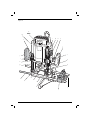
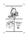
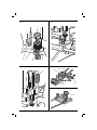
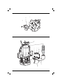
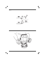
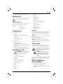
www.
.eu
DW624
DW625E
Copyright DEWALT
2
Figure 1A
b
DW625
nn
l
m
k
n
a
xxxx xx xx
4
j
o
j
i
p
h
q
g
c
f
e
d
u
t
r
s
1
Figure 1B
j
a
w
n
c
v
Figure 3
Figure 2
c
y
x
2
c
d
Figure 4
Figure 5
aa
q
t
a
i
g
l
Figure 6
Figure 7
k
f
bb
l
s
cc
r
m
Figure 8
v
w
q
3
Figure 9
u
ee
ff
Figure 10
jj
ll
ii
ll
hh
kk
4
Figure 11
Figure 12
5
EN GLI S H
ROUTER
DW624, DW625E
WARNING: The declared vibration
emission level represents the main
applications of the tool. However if the
tool is used for different applications,
with different accessories or poorly
maintained, the vibration emission may
differ. This may significantly increase the
exposure level over the total working
period.
Congratulations!
You have chosen a DEWALT tool. Years of
experience, thorough product development and
innovation make DEWALT one of the most reliable
partners for professional power tool users.
Technical Data
Voltage
UK & Ireland
Type
Power input
Power output
No-load speed
Router carriage
Router carriage stroke
Revolver depth stop
VDC
VDC
W
W
min-1
mm
DW624
DW625E
230
230
230/115
230/115
1
6
1,600
2,000
960
1,110
20,000 8,000–20,000
2 columns 2 columns
62
62
3-step, with 3-step,with
graduation graduation
and fine
and fine
adjustment adjustment
1/2
1/2
50
50
5.2
5.2
Collet size
Cutter diameter, max.
Weight
inch
mm
kg
LPA (sound pressure)
KPA (sound pressure
uncertainty)
LWA (sound power)
KWA (sound power
uncertainty)
dB(A)
96
92
dB(A)
dB(A)
3
103
3
100
dB(A)
2.9
3.4
An estimation of the level of exposure to
vibration should also take into account
the times when the tool is switched off
or when it is running but not actually
doing the job. This may significantly
reduce the exposure level over the total
working period.
Identify additional safety measures to
protect the operator from the effects of
vibration such as: maintain the tool and
the accessories, keep the hands warm,
organisation of work patterns.
Fuses
Europe
U.K. & Ireland
U.K. & Ireland
230 V tools
230 V tools
115 V tools
10 Amperes, mains
13 Amperes, in plugs
16 Amperes, in plugs
Definitions: Safety Guidelines
Vibration total values (triax vector sum) determined according to
EN 60745:
Vibration emission value ah
ah =
m/s²
Uncertainty K =
m/s²
4.6
2.6
3.1
1.5
The vibration emission level given in this information
sheet has been measured in accordance with a
standardised test given in EN 60745 and may be
used to compare one tool with another. It may be
used for a preliminary assessment of exposure.
The definitions below describe the level of severity
for each signal word. Please read the manual and
pay attention to these symbols.
DANGER: Indicates an imminently
hazardous situation which, if not avoided,
will result in death or serious injury.
WARNING: Indicates a potentially
hazardous situation which, if not
avoided, could result in death or
serious injury.
CAUTION: Indicates a potentially
hazardous situation which, if not
avoided, may result in minor or
moderate injury.
NOTICE: Indicates a practice not
related to personal injury which, if
not avoided, may result in property
damage.
Denotes risk of electric shock.
6
E NG L I S H
Denotes risk of fire.
b)
EC-Declaration of Conformity
MACHINERY DIRECTIVE
DW624, DW625E
DEWALT declares that these products described
under “technical data” are in compliance with:
2006/42/EC, EN 60745-1, EN 60745-2-17.
These products also comply with Directive
2004/108/EC. For more information, please contact
DEWALT at the following address or refer to the
back of the manual.
The undersigned is responsible for compilation of the
technical file and makes this declaration on behalf of
DEWALT.
Horst Grossmann
Vice President Engineering and Product
Development
DEWALT, Richard-Klinger-Straße 11,
D-65510, Idstein, Germany
31.12.2009
WARNING: To reduce the risk of injury,
read the instruction manual.
General Power Tool Safety Warnings
WARNING! Read all safety warnings
and all instructions. Failure to follow
the warnings and instructions may result
in electric shock, fire and/or serious
injury.
SAVE ALL WARNINGS AND INSTRUCTIONS
FOR FUTURE REFERENCE
The term “power tool” in the warnings refers to your
mains-operated (corded) power tool or batteryoperated (cordless) power tool.
1) WORK AREA SAFETY
a) Keep work area clean and well lit.
Cluttered or dark areas invite accidents.
c)
Do not operate power tools in explosive
atmospheres, such as in the presence of
flammable liquids, gases or dust. Power
tools create sparks which may ignite the dust
or fumes.
Keep children and bystanders away while
operating a power tool. Distractions can
cause you to lose control.
2) ELECTRICAL SAFETY
a) Power tool plugs must match the outlet.
Never modify the plug in any way. Do
not use any adapter plugs with earthed
(grounded) power tools. Unmodified plugs
and matching outlets will reduce risk of
electric shock.
b) Avoid body contact with earthed or
grounded surfaces such as pipes,
radiators, ranges and refrigerators. There
is an increased risk of electric shock if your
body is earthed or grounded.
c) Do not expose power tools to rain or wet
conditions. Water entering a power tool will
increase the risk of electric shock.
d) Do not abuse the cord. Never use the
cord for carrying, pulling or unplugging
the power tool. Keep cord away from
heat, oil, sharp edges or moving parts.
Damaged or entangled cords increase the
risk of electric shock.
e) When operating a power tool outdoors,
use an extension cord suitable for outdoor
use. Use of a cord suitable for outdoor use
reduces the risk of electric shock.
f) If operating a power tool in a damp
location is unavoidable, use a residual
current device (RCD) protected supply.
Use of an RCD reduces the risk of electric
shock.
3) PERSONAL SAFETY
a) Stay alert, watch what you are doing and
use common sense when operating a
power tool. Do not use a power tool while
you are tired or under the influence of
drugs, alcohol or medication. A moment of
inattention while operating power tools may
result in serious personal injury.
b) Use personal protective equipment.
Always wear eye protection. Protective
equipment such as dust mask, non-skid
safety shoes, hard hat, or hearing protection
used for appropriate conditions will reduce
personal injuries.
c) Prevent unintentional starting. Ensure
the switch is in the off position before
connecting to power source and/or
battery pack, picking up or carrying the
7
EN GLI S H
d)
e)
f)
g)
tool. Carrying power tools with your finger
on the switch or energising power tools that
have the switch on invites accidents.
Remove any adjusting key or wrench
before turning the power tool on. A
wrench or a key left attached to a rotating
part of the power tool may result in personal
injury.
Do not overreach. Keep proper
footing and balance at all times. This
enables better control of the power tool in
unexpected situations.
Dress properly. Do not wear loose
clothing or jewellery. Keep your hair,
clothing and gloves away from moving
parts. Loose clothes, jewellery or long hair
can be caught in moving parts.
If devices are provided for the connection
of dust extraction and collection facilities,
ensure these are connected and properly
used. Use of dust collection can reduce
dust-related hazards.
4) POWER TOOL USE AND CARE
a) Do not force the power tool. Use the
correct power tool for your application.
The correct power tool will do the job
better and safer at the rate for which it
was designed.
b) Do not use the power tool if the switch
does not turn it on and off. Any power
tool that cannot be controlled with the switch
is dangerous and must be repaired.
c) Disconnect the plug from the power
source and/or the battery pack from
the power tool before making any
adjustments, changing accessories, or
storing power tools. Such preventive safety
measures reduce the risk of starting the
power tool accidentally.
d) Store idle power tools out of the reach
of children and do not allow persons
unfamiliar with the power tool or these
instructions to operate the power tool.
Power tools are dangerous in the hands of
untrained users.
e) Maintain power tools. Check for
misalignment or binding of moving parts,
breakage of parts and any other condition
that may affect the power tool’s operation.
If damaged, have the power tool repaired
before use. Many accidents are caused by
poorly maintained power tools.
f) Keep cutting tools sharp and clean.
Properly maintained cutting tools with sharp
cutting edges are less likely to bind and are
easier to control.
8
g)
Use the power tool, accessories and
tool bits etc., in accordance with these
instructions taking into account the
working conditions and the work to
be performed. Use of the power tool for
operations different from those intended
could result in a hazardous situation.
5) SERVICE
a) Have your power tool serviced by a
qualified repair person using only identical
replacement parts. This will ensure that the
safety of the power tool is maintained.
Additional Specific Safety Rules for
Cutters
• Always use cutters with a shank diameter
corresponding to the size of the collet installed
in your tool.
• Always use cutters suitable for a speed of
30,000 min-1 and marked accordingly.
• Never use cutters with a diameter exceeding the
maximum diameter indicated in the technical
data.
This router is designed to acept professional cutters
of straight, profile, rabbet, and grooved type with
rated minimum speed of 30,000/min.
WARNING! Always consider the
following compulsive conditions:
• Use 12 mm shank diameter for
straight, rabbet, groove and profile
cutter
• Maximum cutter diameter:
DW624: 40 mm at 35 mm cutting
depth
DW625E: 50mm at 35 mm cutting
depth
DW624 & DW625E
Groove Cutter: 50 mm at 6 mm
cutting depth
Residual Risks
In spite of the application of the relevant safety
regulations and the implementation of safety
devices, certain residual risks cannot be avoided.
These are:
– Impairment of hearing.
– Risk of personal injury due flying particles.
– Risk of burns due to accessories becoming hot
during operation.
E NG L I S H
– Risk of personal injury due to prolonged use.
Markings on Tool
The following pictograms are shown on the tool:
Read instruction manual before use.
l. Measuring lens
m. Scale
n. Plunge lock
o. Clamping screw
p. Depth stop
q. Fine adjuster for depth stop
DATE CODE POSITION (FIG. 1)
r. Fine adjuster for parallel fence
The Date Code (nn), which also includes the year of
manufacture, is printed into the housing.
s. Parallel fence
Example:
u. Router base
2010 XX XX
Year of Manufacture
Package Contents
The package contains:
1 Router
1 Parallel fence with fine adjustment and
guide rods
t. Revolver depth stop
v. Baseplate extension
w. Guiding knob
INTENDED USE
Your DEWALT high performance DW624/DW625E
router has been designed for professional heavy
duty routing of wood, wood products and plastics.
applications.
1 Spanner #22
DO NOT use under wet conditions or in presence of
flammable liquids or gases.
1 Dust extraction adapter
These routers are professional power tools.
1 Guide bush
DO NOT let children come into contact with the
tool. Supervision is required when inexperienced
operators use this tool.
1 Instruction manual
1 Exploded drawing
• Check for damage to the tool, parts or
accessories which may have occurred during
transport.
• Take the time to thoroughly read and
understand this manual prior to operation.
Description (fig. 1A, 1B)
WARNING: Never modify the power
tool or any part of it. Damage or
personal injury could result.
a. On/off-switch
b. Speed control dial (DW625E)
c. Collet nut
d. Spindle lock
e. Parallel fence locking bolt
f. Guide rods for parallel fence
g. Threaded spindle
h. Stop
i. Knurled nut
j. Grips
Electrical Safety
The electric motor has been designed for one
voltage only. Always check that the power supply
corresponds to the voltage on the rating plate.
Your DEWALT tool is double insulated in
accordance with EN 60745; therefore no
earth wire is required.
WARNING: 115 V units have to
be operated via a fail-safe isolating
transformer with an earth screen
between the primary and secondary
winding.
If the supply cord is damaged, it must be replaced
by a specially prepared cord available through the
DEWALT service organisation.
Mains Plug Replacement
(U.K. & Ireland Only)
If a new mains plug needs to be fitted:
• Safely dispose of the old plug.
• Connect the brown lead to the live terminal in
the plug.
k. Handwheel
9
EN GLI S H
• Connect the blue lead to the neutral terminal.
WARNING: No connection is to be
made to the earth terminal.
Turn the electronic speed control dial to the required
level. The correct setting, however, is a matter of
experience.
1 = 8,000 min-1
Follow the fitting instructions supplied with good
quality plugs. Recommended fuse: 13 A.
2 = 12,000 min-1
Using an Extension Cable
4 = 18,000 min-1
If an extension cable is required, use an approved
extension cable suitable for the power input of this
tool (see technical data). The minimum conductor
size is 1 mm2; the maximum length is 30 m.
5 = 20,000 min-1
3 = 16,000 min-1
Adusting the Depth of Cut (fig. 1A)
When using a cable reel, always unwind the cable
completely.
Your router is equipped with a high precision depth
adjustment system including a revolver depth stop
(t), a measuring lens (l) and fine adjuster (q).
ASSEMBLY AND ADJUSTMENTS
Quick Adjustment (fig. 1A, 4)
WARNING: To reduce the risk of
injury, turn unit off and disconnect
machine from power source before
installing and removing accessories,
before adjusting or changing setups or when making repairs. Be sure
the trigger switch is in the OFF position.
An accidental start-up can cause injury.
Inserting and Removing a Cutter
(fig. 2)
1. Press and hold down the spindle lock (d).
2. Using the 22 mm wrench, loosen the collet nut
(c) a few turns and insert a cutter (x).
3. Tighten the collet nut and release the spindle
lock.
WARNING: Never tighten the collet
nut without a cutter in the collet.
1. Loosen the plunge lock (n) by pulling it up.
2. Lower the router carriage until the cutter is in
contact with the workpiece.
3. Tighten the plunge lock (n) by pushing it down.
4. For optimum ease of operation, the carriage
return can be adapted to the required depth of
cut by rotating or sliding the knurled nut (i).
5. Loosen the clamping screw.
6. Rotate the handwheel (k) until the fine adjuster
(q) touches the revolver depth stop (t).
7. Set the measuring lens to a round figure
(e.g. 0).
8. Adjust the depth of cut using the handwheel
(k) and the measuring lens (l). The distance
between the top of the revolver depth stop and
the bottom of the fine adjuster is the adjusted
depth of cut.
9. Tighten the clamping screw (o).
Replacing the Collet. (fig. 3)
Your router is supplied with a 1/2" collet fitted to the
tool. Other precision collets are also available to suit
the cutter used.
1. Separate the collet (y) from the collet nut (c) by
pulling it firmly.
2. Click the new collet in place.
Setting the Electronic Speed Control
Dial (fig. 1A)
DW625E
The speed is infinitely variable from 8,000 to 20,000
min-1 using the electronic speed control dial (b) for
uniform cutting results in all types of wood and
plastics.
10
Triple Depth Adjustment Using the
Revolver Depth Stop (fig. 5)
The revolver depth stop (t) can be used to set three
different depths. This is particularly useful for deep
cuts, performed in steps.
1. Place a depth template between the fine
adjuster (q) and the revolver depth stop (t) to
adjust the exact cutting depth.
2. If required, set all three screws.
WARNING: Make shallow cuts only!
E NG L I S H
Fine Adjustments (fig. 6)
When not using a depth template, or if the depth of
cut needs readjustment, it is recommended to use
the fine adjuster (q).
1. Adjust the depth of cut using the fine
adjuster (q).
Fitting the Baseplate Extension
(Option) (fig. 1B, 8)
1. Fit the baseplate extension (v) to the free end of
the guide rods.
2. Guide the tool with one hand on the knob (w)
and the other on the opposite grip (j).
2. Read the depth of cut using the measuring lens
(l) and scale (m).
Fitting a Guide Bush (fig. 9)
3. Adapt the depth of cut to the millimeter using
the handwheel (k).
Together with a template, guide bushes play a
valuable part in cutting and shaping to a pattern.
Depth Adjustment with the Router
Installed in Inverted Position (fig. 4)
1. Remove the cap nut (aa) and the knurled knob
(i) and replace it with the height adjusting tool
(DE6966) available as an option.
2. Screw the threaded end of the height adjusting
tool to the threaded spindle (g).
3. Set the depth of cut using the adjuster on the
height adjusting tool.
WARNING: For installing the router
in inverted position, refer to the relevant
instruction manual on the stationary tool.
Fitting the Parallel Fence (fig. 1A, 7)
1. Fit the guide rod (f) to the router base (u).
2. Slide the parallel fence (s) over the rods.
3. Tighten the locking bolts (e) temporarily.
Adjusting the Parallel Fence
(fig. 1A, 7)
• Fit the guide bush (ee) to the router base (u)
using the screws (ff) as shown.
Connecting a Dust Extractor
(fig. 1A, 10)
The dust extraction adaptor consists of a main
section (hh), a cover (ii), a hose guide (jj), two screws
(kk) and two nuts (ll).
1. Slide the cover (ii) onto the main section (hh)
and let it click into place.
2. Connect a dust extractor hose to the dust
extraction adaptor.
3. Loosen the screw in the top of the router and fit
the hose guide (jj) as shown.
Prior to Operation
1. Check that the cutter is correctly installed in the
collet.
2. Set the cutting depth.
1. Draw a cutting line on the material.
3. Connect a dust extractor.
2. Lower the router carriage until the cutter is in
contact with the workpiece.
4. Make sure the plunge limiter is always locked
before switiching on.
3. Tighten the plunge lock (n) and limit the carriage
return using the knurled nut (i).
4. Position the router on the cutting line.
5. Slide the parallel fence (s) against the workpiece
and tighten the locking bolts (e).
6. Adjust the parallel fence using the fine adjuster
(r). The outer cutting edge of the cutter must
coincide with the cutting line.
7. If required, loosen the screws (bb) and adjust
the strips (cc) to obtain the desired guiding
length.
OPERATION
Instructions for Use
WARNING: Always observe the safety
instructions and applicable regulations.
WARNING: To reduce the risk
of serious personal injury, turn
tool off and disconnect tool from
power source before making any
adjustments or removing/installing
attachments or accessories.
11
EN GLI S H
WARNING:
Routing with Pilot Cutters (fig. 2)
• Always observe the safety instructions
and applicable regulations.
Where a parallel guide or guide bush are
inappropriate, it is possible to use pilot cutters (x) for
cutting shaped edges.
• Always move your router as indicated
in fig. L (outer edges/inner edges).
Proper Hand Position (fig. 1, 12)
WARNING: To reduce the risk of
serious personal injury, ALWAYS use
proper hand position as shown.
WARNING: To reduce the risk of
serious personal injury, ALWAYS hold
securely in anticipation of a sudden
reaction.
Proper hand position requires one hand on the each
grip (j), as shown.
Switching On and Off (fig. 1A, 4)
1. On: pull the switch (a) up.
2. Off: press the switch (a) down.
WARNING: Loosen the plunge limiter
and allow the router carriage to regain
its rest position before switching off.
These include collets (6 - 12.7 mm), a height
adjusting tool and router table for use in inverted
position, finger jointing tools for dovetail and finger
jointing jigs, dovetail jointing templates, adjustable
guide bush holder and guide bushes and guide rails
in various lengths.
MAINTENANCE
Your DEWALT power tool has been designed to
operate over a long period of time with a minimum
of maintenance. Continuous satisfactory operation
depends upon proper tool care and regular cleaning.
WARNING: To reduce the risk of
injury, turn unit off and disconnect
machine from power source before
installing and removing accessories,
before adjusting or changing
set-ups or when making repairs.
Be sure the trigger switch is in the OFF
position. An accidental start-up can
cause injury.
Using the Guide Bushes (fig. 9)
1. Secure the template to the workpiece using end
clamps.
2. Select and install an appropriate guide bush
(ee).
3. Subtract the diameter of the cutter from the
outside diameter of the guide bush and divide
by 2. This is the difference between template
and workpiece.
WARNING: If the work piece is not thick
enough, place it on a piece of waste
wood.
Guiding Off a Batten
Where an edge guide cannot be used, it is also
possible to guide the router along a batten clamped
across the workpiece (with an overhang at both
ends.)
Freehand Routing
Your router can also be used without any sort of
guide, e.g. for signwriting or creative work.
WARNING: Make shallow cuts only!
Use cutters with a max. diameter of
6 mm.
12
Lubrication
Your power tool requires no additional lubrication.
Cleaning
WARNING: Blow dirt and dust out of
the main housing with dry air as often as
dirt is seen collecting in and around the
air vents. Wear approved eye protection
and approved dust mask when
performing this procedure.
WARNING: Never use solvents or
other harsh chemicals for cleaning the
non-metallic parts of the tool. These
chemicals may weaken the materials
used in these parts. Use a cloth
dampened only with water and mild
soap. Never let any liquid get inside the
tool; never immerse any part of the tool
into a liquid.
E NG L I S H
Optional Accessories
WARNING: Since accessories, other
than those offered by DEWALT, have
not been tested with this product, use
of such accessories with this tool could
be hazardous. To reduce the risk of
injury, only DEWALT, recommended
accessories should be used with this
product.
Consult your dealer for further information on the
appropriate accessories.
Protecting the Environment
Separate collection. This product must
not be disposed of with normal
household waste.
Should you find one day that your DEWALT product
needs replacement, or if it is of no further use to you,
do not dispose of it with household waste. Make this
product available for separate collection.
Separate collection of used products and
packaging allows materials to be
recycled and used again. Re-use of
recycled materials helps prevent
environmental pollution and reduces
the demand for raw materials.
Local regulations may provide for separate collection
of electrical products from the household, at
municipal waste sites or by the retailer when you
purchase a new product.
DEWALT provides a facility for the collection and
recycling of DEWALT products once they have
reached the end of their working life. To take
advantage of this service please return your product
to any authorised repair agent who will collect them
on our behalf.
You can check the location of your nearest
authorised repair agent by contacting your local
DEWALT office at the address indicated in this
manual. Alternatively, a list of authorised DEWALT
repair agents and full details of our after-sales
service and contacts are available on the Internet at:
www.2helpU.com.
GUARANTEE
DEWALT is confident of the quality of its
products and offers an outstanding guarantee
for professional users of the product. This
guarantee statement is in addition to and in
no way prejudices your contractual rights as a
professional user or your statutory rights as a
private non-professional user. The guarantee
is valid within the territories of the Member
States of the European Union and the
European Free Trade Area.
• 30 DAY NO RISK
SATISFACTION GUARANTEE •
If you are not completely satisfied with the
performance of your DEWALT tool, simply
return it within 30 days, complete with all
original components, as purchased, to
the point of purchase, for a full refund or
exchange. The product must have been
subject to fair wear and tear and proof of
purchase must be produced.
• ONE YEAR FREE SERVICE CONTRACT •
If you need maintenance or service for your
DEWALT tool, in the 12 months following
purchase, it will be undertaken free of charge
at an authorised DEWALT repair agent. Proof
of purchase must be produced. Includes
labour. Excludes accessories and spare parts
unless failed under warranty.
• ONE YEAR FULL WARRANTY •
If your DEWALT product becomes defective
due to faulty materials or workmanship
within 12 months from the date of purchase,
DEWALT guarantees to replace all defective
parts free of charge or – at our discretion –
replace the unit free of charge provided that:
• The product has not been misused;
• The product has been subject to fair
wear and tear;
• Repairs have not been attempted by
unauthorised persons;
• Proof of purchase is produced;
• The product is returned complete with all
original components.
If you wish to make a claim, contact your
seller or check the location of your nearest
authorised DEWALT repair agent in the
DEWALT catalogue or contact your DEWALT
office at the address indicated in this manual.
A list of authorised DEWALT repair agents and
full details of our after-sales service is available
on the Internet at: www.2helpU.com.
13
Belgique et Luxembourg
België en Luxemburg
Black & Decker - DEWALT
Nieuwlandlaan 7, IZ Aarschot B156
B-3200 Aarschot
Tel:
+32 (0)015 - 15 47 9211
Fax:
+32 (0)015 - 15 47 9210
www.dewalt.be
Danmark
DEWALT
Sluseholmen 2-4
2450 København SV
Tlf:
70201511
Fax:
70224910
www.dewalt.dk
Deutschland
DEWALT
Richard-Klinger-Straße
65510 Idstein
Tel:
06126-21-1
Fax:
06126-21-2770
www.dewalt.de
Ελλάς
Black & Decker (Hellas) S.A.
Στράβωνος 7 & Βουλιαγμένης 159
Γλυφάδα 16674, Αθήνα
Τηλ:
(01) 8981-616
Φαξ:
(01) 8983-570
Service: (01) 8982-630
España
DEWALT
Parque de Negocios “Mas Blau”
Edificio Muntadas, c/Bergadá, 1, Of. A6
08820 El Prat de Llobregat (Barcelona)
Tel:
934 797 400
Fax:
934 797 439
www.dewalt.es
France
DEWALT
5, allée des hêtres
BP 30084, 69579 Limonest Cedex
Tel:
04 72 20 39 20
Fax:
04 72 20 39 00
www.dewalt.fr
Schweiz
Suisse
Svizzera
DEWALT
In der Luberzen 40
8902 Urdorf
Tel:
01 - 730 67 47
Fax:
01 - 730 70 67
www.dewalt.ch
Ireland
DEWALT
Calpe House Rock Hill
Black Rock, Co. Dublin
Tel:
00353-2781800
Fax:
00353-2781811
www.dewalt.ie
Italia
DEWALT
Viale Elvezia 2
20052 Monza (Mi)
Tel:
800-014353
Fax:
039-2387592
www.dewalt.it
Nederlands
Black & Decker - DEWALT
Joulehof 12
4600 AB Bergen Op Zoom
Tel:
0164 283000
Fax:
0164 283100
www.dewalt.nl
Norge
DEWALT
Postboks 4814, Nydalen
0422 Oslo
Tel:
22 90 99 00
Fax:
22 90 99 01
www.dewalt.no
Österreich
DEWALT
Werkzeugevertriebs GmbH
Erlaaerstraße 165, Postfach 320,1231 Wien
Tel:
01 - 66116 - 0
Fax:
01 - 66116 - 14
www.dewalt.at
Portugal
DEWALT
Rua Egas Moniz 173
João do Estoril, 2766-651 Estoril
Tel:
214 66 75 00
Fax:
214 66 75 75
www.dewalt.pt
Suomi
DEWALT Oy
Tekniikantie 12
02150 Espoo, Finland
Puh:
010 400 430
Faksi: 0800 411 340
www.dewalt.fi
DEWALT Oy
Teknikvägen 12
02150 Esbo, Finland
Tel:
010 400 430
Fax:
0800 411 340
www.dewalt.fi
Sverige
DEWALT
Box 94
431 22 Mölndal
Tel:
031 68 61 00
Fax:
031 68 60 08
www.dewalt.se
Türkiye
KALE Hırdavat ve Makina A.Ş.
Defterdar Mah. Savaklar Cad. No:15
Edirnekapı / Eyüp / İSTANBUL 34050 TÜRKİYE
Tel:
0212 533 52 55
Faks: 0212 533 10 05
www.dewalt.com.tr
United Kingdom
DEWALT
210 Bath Road
Slough, Berks SL1 3YD
Tel:
01753-56 70 55
Fax:
01753-57 21 12
www.dewalt.co.uk
N050111
03/10