1
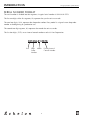
Service and Parts Manual
Supplement
For Models
• 2075DWRR • CO2075DWR • 2075DWRWC
U-Line Corporation
8900 North 55th Street
Milwaukee, WI 53223
U-Line Corporation
PO Box 245040
Milwaukee, WI 53224-9540
www.U-LineService.com
Phone (414) 354-0300 • FAX (414) 354-7905
Service & Parts Tech Lines Phone (800) 779-2547 • FAX (414) 354-5696
MADE IN
THE
USA
INTRODUCTION
Design ■ Features ■ Performance
General Information
2075DWRR
2075DWRWC
CO2075DWR
1
Design ■ Features ■ Performance
NOTES
2
INTRODUCTION
Design ■ Features ■ Performance
INTRODUCTION
Three generations of pride and quality manufacturing and design improvements are built into all U-Line
products. The result: U-Line leads the market with innovative technology and superior craftsmanship.
This manual contains specific instructions for servicing the U-Line Échelon 2075DWRR, CO2075DWR and
2075DWRWC.
Potential Problems With HFC-134A
This Service Manual has been written to cover product manufactured with HFC-134a. HFC-134A compressors will be received with a synthetic based ester oil charge. The hygroscopic (water attraction) property of
ester oil is many times greater than that of the mineral oils previously used with CFC-12. High system
moisture causes the formation of acids and alcohol which can damage the compressor. Systems should not
be left open for more than fifteen (15) minutes at any time as humidity from the air will enter system. To
assure system dehydration, the system should be pulled down to 100 microns and vacuum pump oil (mineral oil) must not be allowed to enter the system.
Cleanliness of the system will be extremely important. The presence of residues (chlorinated or greasy
residues, mineral oil, or impurities) can lead to capillary tube restrictions, oil return problems and compressor damage. Flux must not be used on brazed joints.
3
INTRODUCTION
Design ■ Features ■ Performance
SERIAL NUMBER FORMAT
The serial number is divided into four segments. A typical serial number is 031234-01-5678.
The first two digits of the first segment, 03, represent the year the unit was made.
The next four digits, 1234, represent the shop order number. Every model is assigned a new shop order
number at the beginning of a production run.
The second two digit segment, 01, represents the month the unit was made.
The last four digits, 5678, are an internal control number used at U-Line Corporation.
031234-01-5678
Year
Shop Month
Order
Number
4
Factory Internal
Control Number
General
Information
GENERAL INFORMATION
Design ■ Features ■ Performance
GENERAL INFORMATION
Design ■ Features ■ Performance
LIMITED WARRANTY
U-Line Corporation warrants each U-Line product to be free from defects in materials and workmanship
for a period of one year from the date of purchase; and warrants the sealed system (consisting of the compressor, the condenser, the evaporator, the hot gas bypass valve, the dryer and the connecting tubing) in
each U-Line product to be free from defects in materials and workmanship for a period of five years from
the date of purchase. During the initial one-year warranty period for all U-Line products U-Line shall: (1)
at U-Line’s option, repair any product or replace any part of a product that breaches this warranty; and (2)
for all Marine, RV and Domestic U-Line products sold and serviced in the United States (including Alaska
and Hawaii) and Canada, U-Line shall cover the labor costs incurred in connection with the replacement
of any defective part. During years two through five of the warranty period for the sealed system, U-Line
shall: (1) repair or replace any part of the sealed system that breaches this warranty; and (2) for all
Marine, RV and Domestic U-Line products sold and serviced in the United States (including Alaska and
Hawaii) and Canada, U-Line shall cover the labor costs incurred in connection with the replacement of
any defective part of the sealed system. All other charges, including transportation charges for replacements under this warranty and labor costs not specifically covered by this warranty, shall be borne by you.
This warranty is extended only to the original purchaser of the U-Line product. The Registration Card
included with the product should be promptly completed by you and mailed back to U-Line, or you can
register on-line at www.U-LineService.com.
The following are excluded from this limited warranty: installation charges; damages caused by disasters or
acts of God, such as fire, floods, wind and lightening; damages incurred or resulting from shipping,
improper installation, unauthorized modification, or misuse/abuse of the product; customer education
calls; food loss/spoilage; door and water level adjustments (except during the first 90 days from the date of
purchase); defrosting the product; adjusting the controls; door reversal; or cleaning the condenser.
If a product defect is discovered during the applicable warranty period, you must promptly notify either the
dealer from whom you purchased the product or U-Line at P.O. Box 23220, Milwaukee, Wisconsin 53223
or at 414-354-0300. In no event shall such notification be received later than 30 days after the expiration
of the applicable warranty period. U-Line may require that defective parts be returned, at your expense, to
U-Line’s factory in Milwaukee, Wisconsin, for inspection. Any action by you for breach of warranty must
be commenced within one year after the expiration of the applicable warranty period.
This limited warranty is in lieu of any other warranty, express or implied, including, but not limited to
any implied warranty of merchantability or fitness for a particular purpose; provided however, that to
the extent required by law, implied warranties are included but do not extend beyond the duration of the
express warranty first set forth above. U-Line’s sole liability and your exclusive remedy under this warranty is set forth in the initial paragraph above. U-Line shall have no liability whatsoever for any incidental, consequential or special damages arising from the sale, use or installation of the product or from any
other cause whatsoever, whether based on warranty (express or implied) or otherwise based on contract,
tort or any other theory of liability.
Some states do not allow limitations on how long an implied warranty lasts or the exclusion or limitation
of incidental or consequential damages, so the above limitations may not apply to you. This warranty gives
you specific legal rights, and you may also have other rights which vary from state to state.
5
GENERAL INFORMATION
Design ■ Features ■ Performance
WARRANTY CLAIMS PROCEDURE
When submitting claims for warranty payment, please follow these guidelines.
You can use any form you would normally use to bill your customer (your own computer generated form,
Narda, USA, etc.).
The model and serial number MUST be on the claims. Claims will not be paid without a model and serial
number.
If you work on more than one unit per service call please submit a separate claim for each unit.
We track all defects through warranty claims, so please be specific on what the repair was. If it is a system
leak, please specify where the leak was.
Please be sure the claim is legible. If the claim form cannot be read, it will be returned, unpaid.
U-Line will not cover part or labor claims for the replacement of a complete ice maker assembly. All ice
maker parts are available as replacement parts and are stocked in our inventory. Remember: we do not
pay customer education calls. Door and water level adjustments are 90 day warranties only.
If you are changing out a unit please supply the model and serial number of both units (the unit being
replaced and the new unit) and the R.A. number.
If a copy of the Proof of Purchase/Install is not available at the site, the technician should record the
following information on the Labor Invoice:
• The name of the selling Dealer
• The date of purchase/installation
• The Order or Invoice number (if available)
• The type of document they saw i.e. Store Receipt, Closing Papers, Sign-Off of Building Permit,
Final Walk Through, etc.
At U-Line, parts and labor claims are paid separately. Included in labor are freon and recovery charges, all
other parts are handled by the parts department. We require that some parts be returned to us, so we may
return them to our vendor. It will be noted on your packing list if we require you to return the part. If a
part is to be returned please include a copy of the packing list and a copy of your claim. If the part was
purchased at one of our part distributors, you must handle the part warranty with that company. For labor
payment please send a readable copy of your claim to U-Line Corporation, P.O. Box 245040, Milwaukee
WI, 53224-9540, for warranty payment, or fax a legible copy to 414-354-5696.
6
GENERAL INFORMATION
Design ■ Features ■ Performance
PARTS LISTING
How to Order Replacement Parts
1. Locate the illustration(s) for the model you are servicing.
2. Refer to the area where the desired part would be installed, locate the part and note the item number
assigned to it.
3. Locate the item number in the left column of the parts listing which is on the next page from the product illustration. Note the full description and the corresponding part number. If this is for a warranty
unit, please indicate and record the model and serial numbers.
4. When ordering parts, it will be necessary to supply us with Model Number, Serial Number, Part
Number, Part Description and in some cases Color or Voltage.
5. U-Line requires the return of the parts listed below if replaced under warranty.
•
•
•
•
•
Fan motors (condenser and evaporator)
Temperature controls
Water solenoid valves
Pumps
Control boards (with thermistors)
•
•
•
Ice maker motors
Bypass solenoids
Compressors (two years old or less - lines
soldered closed)
All warranty parts will be shipped at no charge as long as warranty status has been confirmed. We require
that some parts be returned to us, so we may return them to our vendor. It will be noted on your packing
list if we require you to return a part or if you may field scrap it. If U-Line requires a defective part to be
returned, a prepaid shipping label will be included with your new replacement part. When returning parts
please enclose a copy of your packing list and a copy of your labor claim, showing the model and serial
number, and tag or label the part with the nature of the defect.
Our warranty records may not match the customer’s information. In this case a proof of purchase will be
required. If you do not have the proof of purchase at the time the order is placed, the part will be sent net
15 days (COD if you don’t have an open account with U-Line Corporation). When the proof of purchase is
provided we will credit your account (a check will be sent if the part was sent COD).
6. Parts may be ordered on-line or by FAX or phone.
On-Line:
www.U-LineService.com
FAX Number:
(414) 354-7905
Phone Number: (414) 354-0300 or (414) 354-7885; press 3
To expedite parts shipments, on-line ordering is fastest. When placing FAX orders, copy the FAX Parts
Order Form, located in the back of this manual, when placing an order, or order on-line at
www.u-lineservice.com.
7. Effective immediately, U-Line will not pay warranty claims for the replacement of a complete ice
maker assembly. Complete ice maker assembly replacement is not necessary because all ice maker
parts are available as replacement parts and are stocked in our inventory.
REPLACEMENT PARTS: Use only genuine U-Line replacement parts. The use of non-U-Line parts can
reduce ice rate, cause water to overflow from ice maker mold, damage the unit, and may void the
warranty.
7
GENERAL INFORMATION
Design ■ Features ■ Performance
SAFETY PRECAUTIONS
Do not attempt to service or repair the unit until you have read the entire procedure. Safety items throughout this manual are labeled with Warning or Caution.
! WARNING !
Warning means that failure to follow this safety statement may result in extensive product
damage, serious personal injury, or death.
!
Caution means that failure to follow this safety statement may result in minor or moderate
personal injury, property or equipment damage.
! WARNING !
DANGER: Risk of child entrapment. Before you throw away an old refrigerator or freezer:
Take off the doors, leave shelves in place so that children may not easily climb inside.
! WARNING !
•
•
Never attempt to repair or perform maintenance on the unit until the electricity has been
disconnected.
Altering, cutting of power cord, removal of power cord, removal of power plug, or direct
wiring can cause serious injury, fire and/or loss of property and/or life and will void the
warranty.
!
•
•
•
•
Do not lift unit by door handle.
Never use an ice pick or other sharp instrument to help speed up defrosting. These
instruments can puncture the inner lining or damage the cooling unit.
Failure to clean the condenser every three months can cause the unit to malfunction. This
could void the warranty.
Never install the unit behind closed doors. Be sure front grille is free of obstruction.
Obstructing free air flow can cause the unit to malfunction, and may void the warranty.
8
2075DWRR
2075DWRR
Design ■ Features ■ Performance
2075DWRR
Design ■ Features ■ Performance
COMPRESSOR/ELECTRICAL SPECIFICATIONS
2075DWRR
EMU30HSC
OVERLOAD PROTECTOR
C
RELAY COVER
S
R
STARTING RELAY
UL183-3C
COMPRESSOR PINS
To measure start winding resistance, measure across the C-S pins.
To measure run winding resistance, measure across the C-R pins. These pins should never measure any
resistance to ground. This would indicate a shorted compressor.
Specifications
EMU30HSC Start Winding Resistance:
EMU30HSC Run Winding Resistance:
28 OHMS
8 OHMS
115 VOLT Capacitor:
115 VOLT Valve Coil Resistance:
115 VOLT Drain Pan Heater
12 µF
380 OHMS
6900 OHMS
9
2075DWRR
Design ■ Features ■ Performance
REFRIGERATION SYSTEMS
Normal Vapor/Compression Cycle Refrigeration
•
Refrigerant is pumped from the compressor to the condenser as a high pressure, high temperature
vapor.
•
As the refrigerant cools in the high pressure condenser, the vapor condenses to liquid. During this
phase change, a great amount of heat is rejected with the help of the condenser fan.
•
The liquid then flows to the dryer where it is strained and filtered.
COMPRESSOR
CONDENSER
DRYER
EVAPORATOR
CAPILLARY TUBE
UL183-1
•
From the dryer, the refrigerant flows through the capillary tube which meters the liquid refrigerant to
the evaporator. The pressure of the refrigerant is reduced to the evaporating or low side pressure.
•
The reduction of pressure on the liquid refrigerant causes it to boil or vaporize until it reaches saturation temperature. As the low temperature refrigerant passes through the evaporator coil, it continues to
absorb a lot of heat, causing the boiling action to continue until the refrigerant is completely vaporized. It is during this phase change that the most heat is absorbed (the cooling takes place) in the refrigerator.
•
The refrigerant vapor leaving the evaporator travels through the suction line to the compressor inlet.
The compressor takes the low pressure vapor and compresses it, increasing both pressure and temperature. The hot high pressure gas is pumped out the discharge line and into the condenser. The cycle
continues.
10
2075DWRR
Design ■ Features ■ Performance
THERMISTOR
The thermistor senses the compartment temperature. This is used in conjunction with the control board to
determine the length of the refrigeration cycle.
Thermistors generally fail due to moisture or physical damage.
SERVICE NOTES
2075DWRR
The 2075DWRR has the same basic refrigeration system as the 2075R with a few exceptions.
•
The compressor is a high efficiency Embraco EMU30HSC.
•
The electro-mechanical gas bulb is replaced with an electronic controller. The controller features a
digital temperature display and control with two LED indicators and three touch pad buttons.
•
The mullion between the two drawers has a low wattage “anti sweat” surface heater to prevent condensation on the mullion. Additionally, there is an anti-frost heater on the drain trough.
A thermal cut-out is mounted on the base, where the thermostat is normally mounted. This energy
saving feature cuts-out the “anti-sweat” heater as well as the trough heater in high ambient temperatures, when in most conditions, the mullion would normally be warmed by ambient air.
•
There are two interior lights and light switches. The switches are mounted in a switch box in the rear
interior of the cabinet and the lights, in a housing in the top front of the drawers.
11
2075DWRR
Design ■ Features ■ Performance
THE ELECTRONIC TEMPERATURE CONTROLLERS
2075DWRR
•
The controller has a four minute minimum off-cycle regardless of the thermistor status.
•
The controller has a 4° differential built into it for the refrigerator thermistor. When it senses 38°F, the
refrigerator will cool until the thermistor senses 36°F, and will not re-initiate cooling until the thermistor senses 40°F. When monitoring actual temperature, by pressing WARMER temporarily, the refrigeration cycle may be off, when the temperature is a degree warmer than the set point, or the refrigeration
cycle on, when it is a degree below the set point.
•
The LED status indicator lights indicate compartment temperature is displayed and open thermistor. A
solid light on, in LED position (1), means compartment temperature is displayed. A flashing light, in
LED position (2), means open thermistor. (The thermistor has failed or has been out of limits.) If a
refrigerator thermistor fails, the refrigerator will shut down. A thermistor would normally fail by opening (no continuity), or by shorting (no resistance).
•
Under most conditions, the refrigerator will remain frost-free by clearing itself between refrigeration
cycles. Because there is no thermostat bulb on the evaporator, like other U-Line refrigerators, the controller runs a 45 minute off-cycle for every 12 hours of clock time. The refrigerator will not cool during
this off-cycle even if the refrigerator thermistor is calling for cooling.
•
The entire control system is mounted in a single housing in the top drawer.
12
2075DWRR
Design ■ Features ■ Performance
2075DWRR
1
2
WARMER
SET
TEMP
COOLER
CLRCO011B
The temperature controller is located in the top drawer. The LED display shows the temperature set point
and is calibrated in degrees Fahrenheit. The controller is factory programmed for a set point of 38°F which
will show when the unit is first powered-up.
To display actual temperature, press the “WARMER” button momentarily. A solid status indicator light (1)
will show the air temperature reading in the cabinet for approximately 10 seconds.
To adjust the temperature set point, press the “SET TEMP” button momentarily; the display will flash. Press
the “WARMER” or “COOLER” button as desired to change the set point. When the desired set point shows
on the display, wait 10 seconds and the new set point will be saved. Wait 24 hours for the temperature to
stabilize before checking the actual temperature again. The temperature range is 34°F to 45°F.
Indicator light status
LED
Status
Indicates
1
• Solid
• Flashing
• Compartment temperature displayed
• Not Applicable
2
• Flashing
• Open Thermistor
13
2075DWRR
REFRIGERATION SYSTEM DIAGNOSIS GUIDE
SystemSuction
Condition
Suction
Pressure
Compressor
Line
Evaporator
Tube
Wattage
Normal
Normal
Slightly below
room
temperature
Very hot
Very hot
Warm
Cold
Normal
Overcharge
Higher than
normal
Very cold
may frost
heavily
Slightly warm
to hot
Hot to warm
Cool
Cold
Higher than
normal
Undercharge
Lower than
normal
Warm - near
room
temperature
Hot
Warm
Warm
Extremely cold
near inlet outlet
below room
temperature
Lower than
normal
Partial
Restriction
Somewhat
lower than
normal-in
vacuum
Warm - near
room
temperature
Very hot
Top passes
warm lower passes
cool
(near room
temperature)
due to liquid
Room
temperature
(cool) or
colder
Extremely cold
near inlet outlet
below room
temperature
backing up
Lower than
normal
Complete
Restriction
In deep
vacuum
Room
temperature
(cool)
Room
temperature
(cool)
Room
temperature
(cool)
Room
temperature
(cool)
No
refrigeration
Lower than
normal
No
Gas
0 PSIG
to
25"
Room
temperature
(cool)
Cool
to
hot
Room
temperature
(cool)
Room
temperature
(cool)
No
refrigeration
Lower than
normal
Design ■ Features ■ Performance
Capillary
14
Condenser
Discharge
2075DWRR
Design ■ Features ■ Performance
2075DWRR WIRING DIAGRAM
42184-F
15
2075DWRR
TROUBLESHOOTING
Design ■ Features ■ Performance
! WARNING !
DO NOT service the unit until the main electrical power has
been disconnected.
2075DWRR
1
Not refrigerating (compressor and fan are operating)
Cause
a. Little or no frost pattern on evaporator
2
Not refrigerating (compressor not operating, fan operating)
a.
b.
c.
d.
3
Cause
Wire off or broken
Defective compressor - check resistence
Defective overload
Defective relay
a.
b.
c.
d.
4
Cause
No power to the unit
On/Off switch
Display on - check for power in to controller
Display on - check for power out of controller
Display off
Thermistor light flashing
Display on - power in & out of controller
Cause
Condenser air flow restricted
Condenser fan blade obstructed
Condenser fan motor stalled
Defective Compressor - check resistance
a.
b.
c.
d.
Remedy
Remove restriction (clean condenser and grille)
Remove blade restriction
Replace fan motor
Replace compressor
Compressor will not stop operating
Cause
a. Defective controller
b. Wiring defect
Remedy
a. Replace controller
b. Check wiring
Water leak inside unit
Cause
a. Blocked drain
7
a.
b.
c.
d.
e.
f.
g.
Remedy
Check that unit is plugged in
Check that switch is in the on position
None - Check for bad wire
None - Bad controller
Check transformer
Bad Thermistor
Broken circuit - check wiring
Compressor overheating
a.
b.
c.
d.
6
Remedy
Check wiring
Replace compressor
Replace overload
Replace relay
Not refrigerating (compressor and fan not operating)
a.
b.
c.
d.
e.
f.
g.
5
Remedy
a. Check for sealed system leak or restriction
Remedy
a. Remove blockage
Excessive frost build-up
Cause
a. Gasket not sealing
b. Product too tall for drawer or product not
allowing top bin to move forward (2075DWRR)
16
Remedy
a. Repair or replace gasket
b. Instruct customer
2075DWRR
Design ■ Features ■ Performance
8
Noisy
Cause
a. Copper refrigeration tube touching cabinet
b. Fan blade touching shroud
c. Fan blade obstruction (wiring, foam insulation,
packaging material)
9
Fresh food or wine temperature too cold
a.
b.
c.
d.
10
Remedy
a. Carefully adjust tubing
b. Adjust fan mounting or shroud
c. Remove obstruction
Cause
Controller set too cold
Defective controller
Wiring defect
Thermistor not pushed all the way into the well
a.
b.
c.
d.
Remedy
Adjust controller
Replace controller
Check wiring
Check thermistor location
Excessive condensation on mullion
Cause
Mullion heater not operating - check resistance
a. Good resistance
b. No resistance
Remedy
a. Bad heater switch
b. Heater wiring
Note: The heater will not operate in ambients over 90° F.
17
2075DWRR
Design ■ Features ■ Performance
2075DWRR (1 OF 2)
12
4
5,6
7
8 9
10 11
3
2
1
22
25
14
13
26
7
15
16
24
17
23
18
19
20
DWR023
21
22
19
18
2075DWRR
Design ■ Features ■ Performance
2075DWRR (1 OF 2)
Item
1
2
3
4
5
6
7
8
9
10
11
12
13
14
15
16
17
18
19
20
21
22
23
24
25
26
Description
Control Housing
Control Assembly
Organizer Assembly
Top Bin
Switch Box
Light Switch
Drawer Slides
Evaporator Assembly
Anti-Tip Components
Light Cover
Light Bulb
Back Panel
Drain Trough
Control Harness
Drain Cup
Drain Tube
Grille
Top Drawer (No Front)
Door Gasket
Bottom Drawer (No Front)
Crisper, Bottom
Door Assembly
Crisper Shelf
Door Handle Bottom
Door Handle Top, Modified
Drain Trough Heater
Black
26006
68005
80-48001-00
26000
26010
42179
80-47001-00
2333-S
80-16005-01
11859
31317
11969
31391-3
68015
11508
31726
11902-BLK-01
14007-S
31493-13-BLK
14008-S
26001
2075DRW-FRNT BLK
40000-02
11927-4-BLK
11926-7-BLK
66002
Stainless Steel
26006
68005
80-48001-00
26000
26010
42179
80-47001-00
2333-S
80-16005-02
11859
31317
11969
31391-3
68015
11508
31726
11902-BLK-01
14007-S
31493-13-GRY
14008-S
26001
2075DRW-FRNT SS
40000-02
11927-4-BLK
N/A
66002
Parts Not Shown
Item
Description
Full Door Handle
Black
11926-4-BLK
19
Stainless Steel
N/A
2075DWRR
Design ■ Features ■ Performance
2075DWRR (2 OF 2)
12
13
3
1
2
4
5
10
6
7
8
11
9
14
8
DWR024
20
2075DWRR
Design ■ Features ■ Performance
2075DWRR (2 OF 2)
Item
1
2
3
4
5
6
7
8
9
10
11
12
13
14
Description
Rocker Switch
Transformer
Thermo Cutoff Switch
Condenser
Fan Blade
Fan Motor
Drain Pan
Leg Levelers
Drier
Capacitor
Compressor Assembly
Overload
Relay
Power Cord
Black
2053
68014
66001
2303-S
5188
5263
31550-1-F
41319
2694
71008
70077-S
71009
71010
2887
21
Stainless Steel
2053
68014
66001
2303-S
5188
5263
31550-1-F
41319
2694
71008
70077-S
71009
71010
2887
Design ■ Features ■ Performance
NOTES
22
2075DWRWC
2075DWRWC
Design ■ Features ■ Performance
2075DWRWC
Design ■ Features ■ Performance
COMPRESSOR/ELECTRICAL SPECIFICATIONS
2075DWRWC
EMU30HSC
OVERLOAD PROTECTOR
C
RELAY COVER
S
R
STARTING RELAY
UL183-3C
COMPRESSOR PINS
To measure start winding resistance, measure across the C-S pins.
To measure run winding resistance, measure across the C-R pins. These pins should never measure any
resistance to ground. This would indicate a shorted compressor.
Specifications
EMU30HSC Start Winding Resistance:
EMU30HSC Run Winding Resistance:
28 OHMS
8 OHMS
115 VOLT Capacitor:
115 VOLT Valve Coil Resistance:
12 µF
380 OHMS
23
2075DWRWC
Design ■ Features ■ Performance
REFRIGERATION SYSTEMS
Normal Vapor/Compression Cycle Refrigeration
•
Refrigerant is pumped from the compressor to the condenser as a high pressure, high temperature
vapor.
•
As the refrigerant cools in the high pressure condenser, the vapor condenses to liquid. During this
phase change, a great amount of heat is rejected with the help of the condenser fan.
•
The liquid then flows to the dryer where it is strained and filtered.
COMPRESSOR
TOP
COMPARTMENT
CONDENSER
THERMISTOR
SOLINOID VALVE
DRYER
SOLINOID VALVE
EVAPORATOR
CAPILLARY TUBE
BOTTOM
COMPARTMENT
THERMISTOR
DRYER
EVAPORATOR
CAPILLARY TUBE
DWR052
24
2075DWRWC
Design ■ Features ■ Performance
•
From the dryer, the refrigerant flows through the capillary tube which meters the liquid refrigerant to
the evaporator. The pressure of the refrigerant is reduced to the evaporating or low side pressure.
•
The reduction of pressure on the liquid refrigerant causes it to boil or vaporize until it reaches saturation temperature. As the low temperature refrigerant passes through the evaporator coil, it continues to
absorb a lot of heat, causing the boiling action to continue until the refrigerant is completely vaporized. It is during this phase change that the most heat is absorbed (the cooling takes place) in the refrigerator.
•
The refrigerant vapor leaving the evaporator travels through the suction line to the compressor inlet.
The compressor takes the low pressure vapor and compresses it, increasing both pressure and temperature. The hot high pressure gas is pumped out the discharge line and into the condenser. The cycle
continues.
THERMISTORS
The two thermistors sense the two compartment temperatures. This is used in conjunction with the control
board to determine the length of the refrigeration cycle.
Thermistors generally fail due to moisture or physical damage.
SERVICE NOTES
2075DWRWC
The 2075DWRWC has the same basic refrigeration system as the 2075R/2075WC with a few exceptions.
•
The compressor is a high efficiency Embraco EMU30HSC.
•
The electro-mechanical gas bulb is replaced with an electronic controller. The 2075DWRWC features
an LED display and touch sensors for each drawer and a touch sensor to control the lighting.
•
There are two interior lights and light switches which can be controlled independently from each
other. The switches are mounted in the liner in the rear interior of the cabinet and the lights, in a
housing in the top front of the drawers.
This unit is operated with a two part electronic control assembly. The main board is located in the base of
the unit behind the grille and the display board is permanently attached to the glass in the upper drawer.
There is a snap in access panel in the drawer to reach the back of the board.
The LED display indicates the set point of both compartments. Holding either the up or down arrow for
three seconds enters into the set point mode. You can adjust the temperature of each compartment
independently from 40-60°F.
Holding both the up and down arrow for either section displays the actual temperature.
When the unit is plugged in the top compartment begins cooling first. After the top set point has been
reached the lower compartment will begin cooling. Only one drawer can cool at a time. One compressor
and condenser are used in this system. Behind the compressor are two valves that switch the refrigerant
from the top system to the bottom system. Each system has a bypass valve, dryer, evaporator and capillary
tube. Only one system can operate at a time.
25
2075DWRWC
Design ■ Features ■ Performance
The top and bottom valve can never be open at the same time. After initial startup whichever compartment
calls for cooling first, will have priority. Once the setpoint is achieved the other compartment will be
cooled if necessary.
When both compartments have reached setpoint and the compressor shuts off, the last bypass valve that
was open will remain open for four minutes. This is done to help the refrigerant pressures stabilize and
reduce hard starting of the compressor.
This unit can be put into a diagnostic mode.
1. Unplug unit
2. Install jumper on pins 9 and 10 on board.
3. Plug unit back in.
Based on the attached chart you can turn on and off each relay individually.
TOP DRAWER
THERMISTOR
POT
2
TOP
VALVE
COND/GAS COMPRESSOR
FAN
3
1 2
5
6
7
8 9 10
BOTTOM DRAWER
THERMISTOR
4 5
1
0
DISPLAY BOARD
CONNECTION
-1
-2
-3 -4 -5
BOTTOM
VALVE
POWER
3 4
9 & 10 PINS
CONDENSER
FAN
TOP
LIGHT
BOTTOM
LIGHT
J2
TOP
VALVE
1/4" SPADE
TERMINALS
POWER ON
CLRCO035C
Control pot at 2 – bottom light
Control pot at 0 – top light
Control pot at -2 – bottom bypass valve
Jumper on 1/4" spade terminals – COMPRESSOR
Jump pins on J2 – TOP VALVE
Jump pins on J2 – CONDENSER FAN
26
2075DWRWC
Design ■ Features ■ Performance
THE ELECTRONIC TEMPERATURE CONTROLLERS
2075DWRWC
DWR034
The temperature controls are integrated in the top, front drawer panel. They consist of an LED display and
touch sensors for each drawer and a touch sensor to control the lighting (“ ”, “ ” and “ ”). The LED
displays show the drawer’s temperature set point, and are calibrated in degrees Fahrenheit. The controls
are factory programmed for a set point of 60°F for the top drawer and 40°F for the bottom drawer. Each
drawer’s display will show its set point when the unit is first powered up.
DWR045
To display actual temperature of each drawer, press the “ ” and “ ” touch sensors simultaneously for
three seconds. The display indicates the actual temperature. After approximately 10 seconds, the set point
temperature displays.
Both drawers can be controlled independently from 40°F to 60°F.
To adjust the temperature set point, touch and hold either the “ ” or “ ” for that drawer for three seconds. When the LED displays “SP,” lift your finger from the controller and the corresponding LED will
begin to flash the set point. Touch the “ ” or “ ” until the desired set point displays. Wait 10 seconds
for the new set point to be saved. Wait 24 hours for the temperature to stabilize before checking the actual
temperature again. The compartment set point range is 40°F to 60°F.
27
2075DWRWC
INTERIOR LIGHTING
Design ■ Features ■ Performance
(2075DWRWC)
The interior lighting can be controlled by the controller. Each time the light “
lighting is scrolled through the following options:
Touch
Touch
Touch
Touch
” symbol is touched, the
once – Both compartment lights on.
twice – Top compartment light on.
three times – Bottom compartment light on.
four times – Both compartment lights off.
To enter the “black-out mode,” touch and hold “ ” for approximately 15 seconds, this will turn off both
display temperatures and the cabinet lights. The unit will continue to maintain the compartment set point
temperatures even though they are not displayed. If the light symbol is touched and held for 10 seconds,
the unit will come out of “black-out mode,” the set points will be displayed and the lighting function will
be in one of the four scrolled positions.
Note: When the unit is in “black-out mode,” the light will come on automatically if the drawer is
opened. If you do not want the lights to come on when the drawers are opened, the light bulbs
must be removed. Refer to Light Bulb Replacement.
A solid indicator light (LED dot) indicates a thermistor error in that drawer.
28
System
Condition
Suction
Pressure
Normal
Normal
Overcharge
Higher than
normal
Undercharge
Suction
Line
Condenser
Capillary
Tube
Evaporator
Wattage
Very hot
Very hot
Warm
Cold
Normal
Very cold
may frost
heavily
Slightly warm
to hot
Hot to warm
Cool
Cold
Higher than
normal
Lower than
normal
Warm - near
room
temperature
Hot
Warm
Warm
Extremely cold
near inlet outlet
below room
temperature
Lower than
normal
Partial
Restriction
Somewhat
lower than
normal-in
vacuum
Warm - near
room
temperature
Very hot
Top passes
warm lower passes
cool
(near room
temperature)
due to liquid
Room
temperature
(cool) or
colder
Extremely cold
near inlet outlet
below room
temperature
backing up
Lower than
normal
Complete
Restriction
In deep
vacuum
Room
temperature
(cool)
Room
temperature
(cool)
Room
temperature
(cool)
Room
temperature
(cool)
No
refrigeration
Lower than
normal
No
Gas
0 PSIG
to
25"
Room
temperature
(cool)
Cool
to
hot
Room
temperature
(cool)
Room
temperature
(cool)
No
refrigeration
Lower than
normal
Slightly below
room
temperature
29
2075DWRWC
Compressor
Discharge
Design ■ Features ■ Performance
REFRIGERATION SYSTEM DIAGNOSIS GUIDE
BLACK
GREEN
GROUND
BLACK-NEUTRAL
(RIBBED)
WHITE
WHITE
WHITE
CONTROL BOARD
BOT
VALVE
30
(WHITE) 9
(BLACK) 8
7
(BLACK W/YELLOW) 6
(RED) 5
(YELLOW) 4
(PURPLE) 3
10 9 8 7 6 5 4 3 2 1
(BROWN) 2
(BLUE) 1
BLACK
BLACK
WITH
YELLOW
RED
COND
FAN
YELLOW
PURPLE
BLACK
BROWN
BOTTOM
TOP DRAWER
DRAWER
THERMISTORS
OVERLOAD
BOTTOM
LAMP
BLUE
TOP
LAMP
DISPLAY
BOARD
CONNECTOR
TOP
VALVE
2075DWRWC
BLACK-HOT
(SMOOTH)
2075DWRWC WIRING DIAGRAM
POWER CORD ASSEMBLY
WHITE
BLACK
CAPACITOR
EMBRACO
COMPRESSOR
Design ■ Features ■ Performance
DWR038
RELAY
2075DWRWC
Design ■ Features ■ Performance
TROUBLESHOOTING
! WARNING !
DO NOT service the unit until the main electrical power has
been disconnected.
2075DWRWC
Before servicing this unit, take readings from the electronic control (refer to The Electronic Temperature
Control for checking actual temperatures, if needed). These actual readings are important to take before
having the drawers open for more than 30 seconds to obtain accurate readings.
Top drawer temperature: __________
This temperature should be within a few degrees of the setpoint.
Bottom drawer temperature: _________
This temperature should be within a few degrees of the setpoint.
If there is a dot illuminated above the temperature display, there has been a problem with the thermistor. If
you can read the actual temperatures then the problem has been corrected. If you were unable to read the
temperatures or if you read 99, then the thermistor is not working and the circuit board and thermistors
must be changed. The thermistor harness is matched to the circuit board and these must be changed as an
assembly.
1 Temperatures not cold enough
•
•
•
Check actual temperatures versus setpoint. After 24 hours of runtime, temperatures should be within a few degrees of setpoint.
Drawers left open or not sealing properly.
Clean condenser.
2 Temperatures too cold
•
•
•
•
Check actual temperatures versus setpoint.
Ensure thermistors are pushed all the way into the well tube.
If top drawer is well below setpoint and the lower drawer is not achieving setpoint the thermistors
may be switched.
If bottom drawer is well below setpoint and the upper drawer is not achieving setpoint the valve
power wires may be switched.
31
2075DWRWC
Design ■ Features ■ Performance
3 Drawers will not close properly
•
•
•
The drawer slides contain a self-closing feature which engages when the drawer is about 1 inch
from being closed. At the point the closers engage, there may be some resistance. If this resistance
is hard to overcome, try closing the drawers with more force a couple times and then try slowly
again. If, during shipment, the unit has been mishandled, the drawer slide closers may become disengaged. Reset by closing the drawers with more force than normal.
Ensure large bottles are not restricting rack movement.
Check rail to make sure they are free of contaminents.
4 Cascade parts not operating properly
•
The cam on the cascade mechanism should automatically reset as the drawer is moved fully in and
out. If it does not, manually reset cam.
If the drawer will not close, make sure the cascading cams are positioned correctly. The drawer will
not close if the cams are in the A “open” position. Reset the cams manually as shown in position B
“closed.” The drawers should take a minimal amount of effort to close. See illustration on page 33.
5 LED dot lit on display
•
This light indicates that a thermistor has gone out of range. If the unit is still working the thermistor
is now operational. Unplug unit and plug back in, to clear light. If unit is still not working, change
board and thermistors.
6 Trouble with lights
•
•
•
Each light is controlled by a switch that operates when the drawer is opened and by a touchsensor
in the glass.
Check wiring.
Check bulb.
7 Display not functioning
•
•
•
•
Red LED on rear of display indicates the display has power.
Flashing green indicates communication with main board.
If either is not lit, check wiring to main board.
Could be in Sabbath mode.
8 Not cooling
•
Check solenoid valves and connections.
32
2075DWRWC
Design ■ Features ■ Performance
CASCADING PARTS NOT OPERATING PROPERLY
A - Cascade mechanism in the correct opening position.
DWR065
B - Cascade mechanism in the correct closing position.
33
2075DWRWC
Design ■ Features ■ Performance
2075DWRWC (1 OF 2)
8
7
21
6
5
4
3
2
9,10
1
11
17
22
3
12
14
13
15
16
17
DWR067
20
19
18
34
2075DWRWC
Design ■ Features ■ Performance
2075DWRWC (1 OF 2)
Item
1
2
3
4
5
6
7
8
9
10
11
12
13
14
15
16
17
18
19
20
21
22
Description
Drawer & Rack Assembly Bottom
Drawer & Rack Assembly Top
Cascade Assembly Left Side
Top Rack Assembly
Drawer Slide Assembly
Evaporator Assembly
Anti-Tip Brackets
Back Panel
Lens Cover
Light Bulb
Drain Trough
Drain Funnel
Drain Tube
Grille
Cascading Rack Assembly
Cascade Rack Latch Assembly
Cascade Assembly Right Side
Drawer Wine Caddy Assembly
Door Gasket
Drawer Handle
Interior Slides (White)
Main board jumper wire
Black
80-17030-01
80-17028-01
26028-02-S
80-33005-S
80-47001-00
2649-S
80-16005-01
11969
11859
31317
31391-6
11508
41967-4
11942-BLK-01
80-48003-00
26022-S
26028-01-S
80-48002-00
12094-07-BLK
11949-blk
42118-S
2932
35
Stainless Steel
80-17030-03
80-17028-03
26028-02-S
80-33005-S
80-47001-00
2649-S
80-16005-01
11969
11859
31317
31391-6
11508
41967-4
11942-BLK-01
80-48003-00
26022-S
26028-01-S
80-48002-00
12094-07-BLK
11949
42118-S
2932
2075DWRWC
Design ■ Features ■ Performance
2075DWRWC (2 OF 2)
12
13
1
2
3
11
4
10
9
8
6
7
6
5
DWR068
36
2075DWRWC
Design ■ Features ■ Performance
2075DWRWC (2 OF 2)
Item
1
2
3
4
5
6
7
8
9
10
11
12
13
Description
Board
Condenser Assembly
Fan Blade
Fan Motor
Power Cord
Valve Coil
Valve Assembly
Drier
Compressor Assembly
Leveling Leg
Capacitor
Overload
Relay
Black
68019-S
2303-S
5188
5263
2916
73002
73002-S
2694
70077-S
41319
71008
71009
71010
37
Stainless Steel
68019-S
2303-S
5188
5263
2916
73002
73002-S
2694
70077-S
41319
71008
71009
71010
2075DWRWC
Design ■ Features ■ Performance
NOTES
38
CO2075DWR
CO2075DWR
Design ■ Features ■ Performance
CO2075DWR
Design ■ Features ■ Performance
EMI70HER
OVERLOAD PROTECTOR
C
STARTING RELAY
S
R
RELAY COVER
UL183-3D
COMPRESSOR PINS
To measure start winding resistance, measure across the C-S pins.
To measure run winding resistance, measure across the C-R pins. These pins should never measure any
resistance to ground. This would indicate a shorted compressor.
Specifications
EMI70HER Start Winding Resistance:
EMI70HER Run Winding Resistance:
8 OHMS
3 OHMS
115 VOLT Ice Maker Heater Resistance:
115 VOLT Water Valve Coil Resistance:
115 VOLT Bypass Valve Coil Resistance:
80 OHMS
335 OHMS
380 OHMS
39
CO2075DWR
Design ■ Features ■ Performance
U-LINE FROST FREE REFRIGERATION SYSTEM
Cooling Mode:
• Bypass solenoid valve closed
• Evaporator fan operating
• Refrigerant flows through capillary tube
• Normal vapor/compression cycle refrigeration
Defrost Mode:
• Bypass solenoid valve open
• Refrigerant flows through bypass system
• Vapor flows from condenser to evaporator without a phase change
COMPRESSOR
CONDENSER
DRYER
EVAPORATOR
FLOW WHEN SOLENOID
VALVE IS CLOSED
CAPILLARY TUBE
FLOW WHEN SOLENOID
VALVE IS OPEN
SOLENOID VALVE
UL183-2
THERMISTORS
There are three thermistors to sense the refrigerator, freezer and icemaker temperature. These are used in
conjunction with the control board to control compartment temperatures and initiate ice harvest.
Thermistors generally fail due to moisture or physical damage.
40
CO2075DWR
Design ■ Features ■ Performance
SERVICE NOTES
CO2075DWR
The CO2075DWR has the same basic refrigeration system as the CO2075F with a few exceptions.
•
The compressor is an Embraco EMI70HER.
•
The electro-mechanical gas bulb is replaced with an electronic controller which features a digital
temperature display.
•
The mullion between the two drawers has a low wattage “anti sweat” surface heater to prevent condensation on the mullion.
•
There are two interior lights and light switches. The switches are mounted in the liner in the rear
interior of the cabinet. The lights are in the housing in the top front of the drawers. The bottom light
switch controls the icemaker. When the light switch is on the icemaker stops functioning. If the drawer
is left open, the icemaker will not make ice.
General Operation Notes:
This unit is operated with a two part electronic control assembly. The main board is located in the base of
the unit behind the grille and the display board is located in the upper drawer.
The setpoint button allows the consumer to set a refrigerator temperature. The preset temperature is 38°F.
Based on the design of the mullion and chimney, there is approximately a 38°F difference between freezer
and refrigerator. While the consumer sets the refrigerator temperature the cooling system is actually
controlled by the freezer temperature. When a consumer inputs 38 for the refrigerator, the board subtracts
38 and cools the freezer to 0°F. Use these numbers as reference, but they could be 40°F and 2°F, or 36°F
and -2°F, and so on. The freezer temperature will be maintained at 0°F with a differential of 2°F. In the
event that the refrigerator is warmer than 38°F, but the freezer is 0°F or below, the cooling system will
continue to run to allow the refrigerator to cool to its setpoint. This prevents spoilage of food in the refrigerator. During this time, the freezer may be driven to a lower temperature which will not cause any problems. In the event the refrigerator gets to 32°F it will again override the freezer and cause the cooling system to shut off until the temperature rises above 32°F. This prevents accidental freezing of product in the
refrigerator.
The ice maker setpoint can be reached by holding the “SET TEMP” button down for about 10 seconds. At
first SP1 will be displayed followed by SP2. Release the “SET TEMP” button and 15 should appear. This is
the default ice maker setpoint. Changing this temperature will increase or decrease production. To increase
production raise the setpoint no more than 2°F in 24 hours. Press “SET TEMP” three more times to exit this
menu.
The circuit board has a timing circuit which maintains a minimum compressor off cycle of four minutes. If
the compressor shuts off, no matter what temperature the cabinet rises to, the compressor will remain off
for four minutes to prevent compressor damage.
There is a 30 minute hot gas defrost cycle every 12 hours of clock time. The defrost cycle is automatically
operated by the circuit board. Interrupting power to the unit will reset the clock.
41
CO2075DWR
Design ■ Features ■ Performance
When checking the thermistors to see if they are reading accurately, it is common to place them in an
icebath to see if they read 32°F. Do not place them directly in the water. Use a plastic bag to protect them
from moisture. The freezer and ice maker should read 32°F in icewater, however the refrigerator thermistor should read 36°F. There is a built-in 4°F offset in this reading due to its location in the cabinet. This
sensor is located outside the refrigerator drawer, which is approximately 4°F colder than the inside of the
drawer.
To check the actual temperatures via the display, touch and release the warmer button to view the refrigerator temperature. Hold the colder button, while LED 1 is lit, the freezer temperature will be displayed.
Continue holding the colder button, and the display will cycle from freezer to ice maker until the button is
released.
ICEMAKER FREEZER
SENSOR
SENSOR
9
10
POWER
COMPRESSOR
ICEMAKER
2
3
1 2
3 4
5
6
7
8 9 10
REFRIGERATOR
SENSOR
4 5
1
0
DISPLAY BOARD
CONNECTION
-1
-2
-3 -4 -5
COND/EVAP
FAN
HOT
GAS
POT
HOT GAS
VALVE
J2
ICEMAKER
POWER ON
1/4" SPADE
TERMINALS
CLRCO035B
This unit can be put into a diagnostic mode.
1. Unplug unit
2. Install jumper on pins 9 and 10 on board.
3. Plug unit back in.
Based on the information listed below, you can turn on and off each relay individually.
Control pot at 0 – CONDENSER/EVAPORATOR FANS
Jumper on 1/4" spade terminals – COMPRESSOR
Jump pins on J2 – HOT GAS VALVE
Jump pins on J2 – ICEMAKER
Example (force a defrost cycle):
Set control pot to 0, Jump pins on J2 for hot gas valve and install jumper on 1/4" spade terminals.
42
CO2075DWR
Design ■ Features ■ Performance
THE ELECTRONIC TEMPERATURE CONTROLLER
1
2
3
WARMER
SET
TEMP
COOLER
CLRCO011
The temperature controller is located in the top drawer. It consists of an LED display, two LED status indicator lights and three touch pad buttons. The LED display shows the compartment temperature set point
and is calibrated in degrees Fahrenheit. The controller is factory programmed for a set point of 38°F for the
top drawer which will show when the unit is first powered up. The factory set point for the ice compartment is 0°F.
To display the actual refrigerator compartment temperature, press the “WARMER” button momentarily.
A solid status indicator light (LED 1) will show the air temperature reading in the refrigerator drawer for
approximately 10 seconds.
To adjust the temperature set point, press the “SET TEMP” button momentarily; the display will flash. Press
the “WARMER” or “COOLER” button as desired to change the set point. When the desired set point shows
on the display, you can press the “SET TEMP” again or wait 10 seconds and the new set point will be
saved and the display will stop flashing. Wait 24 hours for the temperature to stabilize before checking the
actual temperature again. The compartment temperature range is 34°F to 45°F.
To check the actual temperatures via the display, touch and release the warmer button to view the
refrigerator (LED 1) temperature. Hold the colder button, while LED 1 is lit, the freezer (LED 2) temperature
will be displayed.
Continue holding the colder button, and the icemaker (LED 3) temperature will be displayed. If you
continue to hold the colder button, the display will cycle from freezer temperature to ice maker
temperature until the button is released.
Indicator light status
LED
Status
Indicates
1
• Solid
• Flashing
• Compartment temperature displayed
• Not Applicable
2
• Solid
• Flashing
• Freezer Temperature displayed
• Open Thermistor – call for service
3
• Solid
• Icemaker temperature displayed
43
System
Condition
Suction
Pressure
Normal
Normal
Overcharge
Higher than
normal
Undercharge
Suction
Line
Condenser
Capillary
Tube
Evaporator
Wattage
Very hot
Very hot
Warm
Cold
Normal
Very cold
may frost
heavily
Slightly warm
to hot
Hot to warm
Cool
Cold
Higher than
normal
Lower than
normal
Warm - near
room
temperature
Hot
Warm
Warm
Extremely cold
near inlet outlet
below room
temperature
Lower than
normal
Partial
Restriction
Somewhat
lower than
normal-in
vacuum
Warm - near
room
temperature
Very hot
Top passes
warm lower passes
cool
(near room
temperature)
due to liquid
Room
temperature
(cool) or
colder
Extremely cold
near inlet outlet
below room
temperature
backing up
Lower than
normal
Complete
Restriction
In deep
vacuum
Room
temperature
(cool)
Room
temperature
(cool)
Room
temperature
(cool)
Room
temperature
(cool)
No
refrigeration
Lower than
normal
No
Gas
0 PSIG
to
25"
Room
temperature
(cool)
Cool
to
hot
Room
temperature
(cool)
Room
temperature
(cool)
No
refrigeration
Lower than
normal
Slightly below
room
temperature
44
Design ■ Features ■ Performance
Compressor
Discharge
CO2075DWR
REFRIGERATION SYSTEM DIAGNOSIS GUIDE
CO2075DWR
Design ■ Features ■ Performance
REFIGERATOR
SENSOR
FREEZER
SENSOR
ICEMAKER
SENSOR
DWR036
CO2075DWR WIRING DIAGRAM
45
CO2075DWR
TROUBLESHOOTING
Design ■ Features ■ Performance
! DANGER !
DO NOT service the unit until the main electrical power has
been disconnected.
Before servicing this unit, take readings from the electronic control (refer to The Electronic Temperature
Control for checking actual temperatures if needed). These actual readings are important to take before
having the drawers open for more than 30 seconds to obtain accurate readings.
Refrigerator temperature: __________
This temperature should be approximately 38°F. Slight fluctuations are common during normal
operation.
Freezer temperature: __________
This temperature should be approximately 0°F. If this temperature is between -10°F and +5°F, this
should be considered normal. The temperature can fluctuate in order to maintain an optimum
refrigerator temperature.
Ice maker temperature: _________
The ice maker will harvest when this temperature reaches 15°F. Temperatures may rise to 50°F
during an ice harvest and drop -10°F during ice storage mode.
If there is a dot illuminated above the temperature display, there has been a problem with the thermistor. If
you can read the actual temperatures then the problem has been corrected. If you were unable to read the
temperatures or if you read 159, then the thermistor is not working and the circuit board and thermistors
must be changed. The thermistor harness is matched to the circuit board and these must be changed as an
assembly.
1. Not making ice
• If temperature reading was above 15°F, the unit will not make ice. Possible causes for this could be
a leak in the system or the drawer left open.
• If temperature reading is below 15°F, the unit should produce ice. If there is no ice in the mold,
check the water fill and water connection. If there is ice in the mold and it did not harvest, close
the freezer drawer, unplug the unit and plug it back in. If the temperature is still below 15°F, the
unit should harvest (drawer must be closed). If the freezer drawer opening caused the ice maker
temperature to go above 15°F, wait until it goes below 15°F.
To harvest ice, the bin arm must be in the down position and the drawer must be closed to engage
the ice maker/light switch, mounted in the liner. When the ice maker reaches 15°F, the circuit
board will close a relay for 30 seconds, energizing the ice maker. When the ice maker rotates to
approximately the 2 o’clock position, it will continue the cycle under its own power and break the
circuit to the control board.
If the ice maker does not harvest after unplugging the unit and plugging it back in, try again and
watch the circuit board to verify the relay energizes by checking the green LED on the board (on
this model you can also accomplish this by using the ON/OFF switch). If the ice maker does not
harvest, but the LED illuminates, check the bin arm circuit and the ice/light switch circuits.
• The ice maker relay will only energize a maximum of one time every 75 minutes of operation,
even if the temperature is below the 15°F harvest temperature. To harvest ice you must unplug the
unit and plug it back in (can use the ON/OFF switch) so that the timer on the circuit board is reset.
The timing circuit ensures that proper cubes are formed before allowing the ice harvest.
46
CO2075DWR
Design ■ Features ■ Performance
2. Some cooling
• Clean condenser.
• Check condenser fan.
• Possible system leak.
3. No cooling
• Check compressor/fan operation
• Check refrigeration system pressure
• Check wiring and power at circuit board
4. Noise
• This is a frost free unit with two fans, compressor, and two solenoid valves. Some noise is normal
such as a hum from the fans/compressor. Also, during an ice harvest it is normal to hear water filling the mold and cubes dropping in the bucket.
5. Condensation on mullion
• The mullion has a heater behind it. The heater is always energized and should keep the mullion
free of frost and sweat. In extremely humid conditions some sweat may appear on the mullion or
lower drawer handle/gasket.
6. Excessive frost
• Frost may be visible through the evaporator cover slots.
• Any buildup on the bottom of the liner could be caused by failure to clean up spilled ice cubes.
• If evaporator is not defrosting, the board can be manually entered into a defrost cycle using the
diagnostic feature.
• If evaporator or drain pan does not clear during a defrost, check the bypass valve coil for continuity.
• Drawers not closing properly.
7. Display not operational
• Check four conductor wires from main board to display board. The display board should have red
light and flashing green light on the rear of the board. If these lights are not lit, the wire is not connecting to the main board.
8. Dot flashing on display
• If a thermistor goes out of range it will illuminate a dot on the display board. This dot will remain lit
even if the thermistor goes back into range. It can be cleared by switching the unit off and back on.
9. Drawers will not close properly
• The drawer slides contain a self-closing feature which engages when the drawer is about 1 inch
from being closed. At the point the closers engage, there may be some resistance. If this resistance
is hard to overcome, try closing the drawers with more force a couple times. If, during shipment,
the unit has been mishandled, the drawer slide closers may become disengaged. Reset by closing
the drawers with more force than normal.
10. Evaporator fan not operational
• Ensure fan is not restricted.
47
CO2075DWR
Design ■ Features ■ Performance
Ice maker Operation
DWR057
1. Freeze cycle
• Ice maker relay is not energized.
• Unit is cooling ice maker down to the 15°F setpoint.
• The unit may cycle on and off as it is pulling ice maker to setpoint in order to maintain ideal
refrigerator and freezer temperatures.
• The minimum ice making cycle time as permitted by the timing circuit in the circuit board is 75
minutes.
48
CO2075DWR
Design ■ Features ■ Performance
2. Harvest cycle 1
DWR058
• Ice maker relay on circuit board energizes for 30 seconds. This allows power to the ice maker to
allow the blades rotate.
• Refrigeration system is independent of the ice maker.
• The bin arm must be in the fully lowered position and the drawer must be closed, to initiate this
cycle. The drawer switch must be depressed for the ice maker to cycle.
49
CO2075DWR
Design ■ Features ■ Performance
3. Harvest cycle 2
DWR055
•
•
•
•
•
The drawer switch must remain depressed for this cycle to continue.
The ice maker relay is now de-energized
This cycle initiates when the blades move to approximately the 2 o’clock position.
Ejector blades stall on the ice and pulse until the mold heater warms the mold and releases the ice.
This cycle may last a couple minutes.
50
CO2075DWR
Design ■ Features ■ Performance
4. Water fill cycle
DWR056
• This cycle initiates when the blades move to approximately the 10 o’clock position.
• At this point the ice has moved out of the mold and is dropping into the bucket.
• The ice maker switch is depressed for about seven seconds while the mold fills with water. The
water fill is approximately 120 ml.
• At the end of the fill cycle, the blades stop at the 12 o’clock position and wait for another harvest
cycle to begin.
5. Storage mode
• The bin arm is in the up position, either held by ice in the bin or manually raised.
• The unit will be cycling the compressor on and off in this mode.
The ice maker relay will energize when the ice maker reaches 15°F, but with the bin arm in the raised
position, it will not start an ice making cycle.
51
CO2075DWR
Design ■ Features ■ Performance
3
4
5
2
1
6
2
DWR041
DISASSEMBLY PROCEDURES
Note: Échelon models do not require removal of the ice maker or freezer housing to access the fan
motor, drain or evaporator.
To
1.
2.
3.
4.
5.
6.
7.
8.
replace evaporator fan motor:
Disconnect unit from power source.
Remove two screws (1) holding evaporator fan cover to evaporator cover.
Unplug fan connection.
Remove two nuts (4) and two washers (5) holding the fan to the fan bracket.
Replace with new fan.
Plug-in the fan connection making sure the fan wires are tucked behind the fan bracket.
Re-install evaporator cover.
Re-install unit and test.
To
1.
2.
3.
4.
5.
6.
7.
access evaporator and drain pan:
Disconnect unit from power source.
Remove two screws (2) holding evaporator cover to drain pan.
Remove two screws (6) holding evaporator to drain pan.
Remove two screws (3) holding fan bracket to drain pan.
Unplug fan connection.
Re-install parts in reverse order.
Re-install unit and test.
52
CO2075DWR
Design ■ Features ■ Performance
REPLACING ICE MAKER ASSEMBLY
2
5
4
1
5
DWR064
3
1.
2.
3.
4.
5.
6.
7.
Remove unit from installation.
Disconnect water and unplug unit.
Disconnect ice maker wire harness at plug in back of unit (1).
Remove thermistor from the sensing tube on ice maker assembly (2).
Remove water inlet tube.
Remove front cover (3).
Advance ejector blade to the 3 o’clock position by turning the 5/16" hex head on the small brass gear
counterclockwise (4).
8. Remove two screws from icemaker bracket (5).
9. Remove ice maker assembly.
10. Install new ice maker assembly.
11. Reconnect plug.
12. Insert thermistor ice maker sensing tube.
13. Insert water inlet tube.
14. Apply Permagum® to all exit holes.
15. Install back panel.
16. Plug in unit and test.
53
CO2075DWR
Design ■ Features ■ Performance
NOTES
54
CO2075DWR
Design ■ Features ■ Performance
REPLACING MOLD AND HEATER
1
6
3
2
5
4
5
3
DWR061
1. Remove ice maker assembly. Refer to REPLACING ICE MAKER ASSEMBLY.
2. Remove one stripper screw (1) and stripper (2).
3. Remove three face plate screws (3) and face plate.
4. Remove one screw (4) and detach limit switch from mold.
5. Detach heater leads (5).
6. Remove two screws (6) and mold from support housing.
7. To assemble, replace parts in reverse order.
8. Install the ice maker assembly.
55
CO2075DWR
Design ■ Features ■ Performance
CO2075DWR (1 OF 3)
10
5
9
8
7
2
6
4
1
3
30
11, 12
13
21
24
23
20
18
22
25
19
17
16
26
15
28 29
14
27
25
DWR025
56
CO2075DWR
Design ■ Features ■ Performance
CO2075DWR (1 OF 3)
Item
1
2
3
4
5
6
7
8
9
10
11
12
13
14
15
16
17
18
19
20
21
22
23
24
25
26
27
28
29
30
Description
Control Housing
Display Board Assembly
Control Harness
Organizer Assembly
Top Bin
Drawer Slides
Light Switch Top Drawer
Chimney
Anti-Tip Components
Back Panel
Light Cover
Light Bulb
Light Switch Bottom Drawer
Evaporator Fan Cover
Evaporator Cover
Insulator Chimney Panel
Evaporator Assembly
Evaporator Fan Blade
Evaporator Fan
Drain Pan Assembly
Drain Tube
Grille
Ice Maker Assembly
Top Drawer (No Door)
Door Gasket
Ice Bucket
Bottom Drawer with Drawer Front
Door Handle Bottom
Door Handle Top, Modified
Door Front Assembly
Black
26006
68024
68025
80-48001-00
26000
80-47002-00
42179
28002
80-16005-01
11969
11859
31317
66003
11952
14039
35005
74002-S
31656
5434
14038
31726
11902-BLK-01
80-39007-00
14007-S
12094-07-BLK
26014
80-17043-01
11927-4-BLK
11926-7-BLK
2075DRW-FRNTBLK
Stainless Steel
26006
68024
68025
80-48001-00
26000
80-47002-00
42179
28002
80-16005-02
11969
11859
31317
66003
11952
14039
35005
74002-S
31656
5434
14038
31726
11902-BLK-01
80-39007-00
14007-S
12094-07-GRY
26014
80-17043-03
11927-4-BLK
N/A
2075DRW-FRNTSS
Parts Not Shown
Item
Description
Full Door Handle
Black
11926-4-BLK
57
Stainless Steel
N/A
CO2075DWR
Design ■ Features ■ Performance
CO2075DWR (2 OF 3)
7
2
4
3
1
8
2
5
6
17 18
16
15
14
9
13
12
11
DWR063
10
58
CO2075DWR
Design ■ Features ■ Performance
CO2075DWR (2 OF 3)
Item
1
2
3
4
5
6
7
8
9
10
11
12
13
14
15
16
17
18
Description
Water Line Assembly
Water Valve
Plastic Nut & Sleeve
Brass Fitting
Drier
Compressor Assembly
Overload
Relay
Power Cord
Leg Levelers
Rocker Switch
Control Board Assembly
Condenser
Drain Pan
Hot Gas Bypass Assembly
Bypass Solenoid Coil Only
Fan Blade
Fan Motor
Black
404-CO2075DWR
2552A
41254
41826
72018
70079-FFS
71025
71026
2915
41319
2053
68023-S
2303-FFS
31550-1-F
73002-FFS
73002-1
5428
5300
59
Stainless Steel
404-CO2075DWR
2552A
41254
41826
72018
70079-FFS
71025
71026
2915
41319
2053
68023-S
2303-FFS
31550-1-F
73002-FFS
73002-1
5428
5300
CO2075DWR
Design ■ Features ■ Performance
CO2075DWR (3 OF 3)
18
13
14
15
16
17
19
12
20
11
21
8
9
3
1
4
5
10
22
6 7
2
30
35
34
33
32
23
25
10
29
28
27
26
31
24
36
60
DWR060
CO2075DWR
Design ■ Features ■ Performance
CO2075DWR (3 OF 3)
Note: This ice maker is used only on CO2075DWR.
!
Use only genuine U-Line replacement parts. U-Line ice maker parts are not the same as
standard FSP Whirlpool parts. Using non-U-Line parts can reduce ice rate, cause water to
overflow from ice maker mold, damage the unit, and may void the warranty.
Item
1
2
3
4
5
6
7
8
9
10
11
12
13
14
15
16
17
Description
Ice Maker Assembly
Faceplate Assembly
Gear Screw
Gear
Face Plate
Motor
Switch Spacer
Hold Switch
Motor Screw
Long SW Screw
Cam
Spring & Housing Screw
Limit Switch
Support Housing
Bin Arm Spring
Bin Arm
Mold Heater
Mold & Heater Assembly
Ejector
Part No.
80-39007-00
150-DWRCO
488957*
628210*
11641*
627973*
625834*
2506*
488622*
488361*
627302*
488372*
2917
625827
627526
18031
625843
628123-DWRCO
627375
Item
18
19
20
21
22
23
24
25
26
27
28
29
30
31
32
33
34
35
36
Description
Waterline Clip
Water Cup
Stripper Screw
Stripper
Sensor Tube
Sensor Tube Retainer
Wire Harness
Bin Switch
Bin SW Screw
Clamp
Arm Lever
Arm Lever Screw
Short SW Screw
Valve Switch
Insulator
Valve Switch Plate
Spring
Plate Screw
Cover
Part No.
652604
544304
489128
31400
23008
14064
2918
2506
488360
625829
625830
627199
488362*
2506*
627680*
625836*
627163*
41375
627000
* Parts included in the 150-DWRCO Faceplate assembly
U-Line will not pay warranty claims for the replacement of a complete ice maker assembly. Complete ice
maker assembly replacement is not necessary because all ice maker parts are available as replacement
parts and are stocked in our inventory.
61
Design ■ Features ■ Performance
NOTES
62
INTRODUCTION
Design ■ Features ■ Performance
NOTES
63
INTRODUCTION
Design ■ Features ■ Performance
NOTES
64
FAX PARTS ORDER FORM
FAX # 414-354-7905
Account# ____________________________________
Ship to:______________________________________
Bill to: ______________________________________
____________________________________________
____________________________________________
____________________________________________
____________________________________________
Attention:
Date:________________________________________
P.O. ________________________________________
Phone#______________________________________
Fax# ________________________________________
PART#
COLOR
QTY
DESCRIPTION
MODEL
SERIAL
NUMBER
UNIT IN
WARRANTY?
SPECIAL INSTRUCTIONS:
All part shipments will be sent ground delivery.
We have air shipment available at an additional cost to you.
Next Day Air
2nd Day Air
3 Day Select
If you do not have an open account with us your order will be shipped C.O.D.
COMMENTS: ________________________________________________________________________________
____________________________________________________________________________________________
Authorized By ________________________________________________
65
P.O. Box 245040
Milwaukee, WI 53224-9540
Phone 414.354.0300
FAX 414.354.7905
Printed in U.S.A. – February 2005
P/N 30017