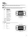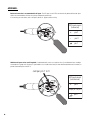
1
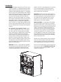
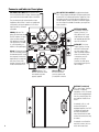
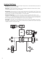
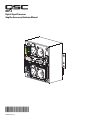
DSP-4
Digital Signal Processor
Amplifer Accessory Hardware Manual
*TD-000103-00*
TD-000103-00 rev.C
IMPORTANT SAFETY PRECAUTIONS & EXPLANATION OF SYMBOLS
The lightning flash with arrowhead symbol within an equilateral triangle is intended to alert the user to the
presence of uninsulated “dangerous” voltage within the product’s enclosure that may be of sufficient magnitude to constitute a risk of electric shock to humans.
The exclamation point within an equilateral triangle is intended to alert the user to the presence of important operating and maintenance (servicing) instructions in this manual.
CAUTION: To reduce the risk of electric shock, do not remove the cover. No user-serviceable parts inside.
Refer servicing to qualified service personnel.
SAFEGUARDS
•Electrical energy can perform many useful functions. This unit has been engineered and manufactured to
assure your personal safety. Improper use can result in potential electrical shock or fire hazards. In order
not to defeat the safeguards, observe the following instructions for its installation, use and servicing.
•Maximum operating ambient temperature is 50° C.
•Never restrict the airflow through the device’s fan or vents.
•When installing equipment into a rack, distribute the units evenly. Otherwise hazardous conditions may
be created by an uneven weight distribution.
•Connect the unit only to a properly rated supply circuit.
•Reliable Earthing (Grounding) of rack-mounted equipment should be maintined.
•To prevent fire or electric shock, do not expose this equipment to rain or moisture.
WARNING!
While QSC has endeavored to develop and produce the most dependable and robust Digital Signal Processor (DSP)
audio product for your use, due to the unlimited and potentially destructive (to the sound system) configurations
that may be applied to the DSP by the user, QSC cannot be held responsible for damages resulting from any deviation or failure by the user to strictly follow the recommendations set forth in the owner’s manual for the integration
of the DSP-4 and Signal Manager software with your sound system.
All risks attendant to integration of user-configurable DSP products with your sound system are assumed by you.
While QSC strives to supply the highest quality technical solutions for Digital Signal Processing, in no event will
QSC or its suppliers be held liable for any damages, consequential, incidental, or otherwise, including any claims
for lost profits and/or savings resulting from any attempted integration of the DSP-4 and Signal Manager software
which does not strictly adhere to the manual’s recommendations.
FCC INTERFERENCE STATEMENT
NOTE: This equipment has been tested and found to comply with the limits for a class B digital device, pursuant to part 15 of the FCC rules. These limits are designed to provide reasonable protection against harmful interference in a residential installation. This equipment generates, uses, and can radiate radio
frequency energy and if not installed and used in accordance to the instructions, may cause harmful interference to radio communications. However, there is no guarantee that interference will not occur in a particular installation. If this equipment does cause harmful interference to radio or television reception,
which can be determined by switching the equipment off and on, the user is encouraged to try to correct
the interference by one or more of the following measures:
- Reorient or relocate the receiving antenna.
- Increase the separation between the equipment and the receiver.
- Connect the equipment into an outlet on a circuit different from that to which the receiver is connected.
- Consult the dealer or an experienced radio or TV technician for help.
© Copyright 2002, 2004 QSC Audio Products, Inc. QSC® is a registered trademark of QSC Audio Products, Inc. “QSC” and the QSC logo are registered
with the U.S. Patent and Trademark Office. All trademarks are the property of their respective owners.
2
Introduction
The DSP-4 is a digital signal processor (DSP ) accessory for
audio power amplifiers. It is designed to reduce the need for
external signal processing while increasing overall system
reliability through distributed intelligence. It is intended primarily for QSC’s CX, DCA, and Powerlight2 series amplifiers
and mounts directly to the rear panel of the 2-RU, 2-channel
models of these amplifiers (pre-August, 1999 date-code of
the CX, DCA and Powerlight2, and all ISA models will
require use of an external power supply). Use of the DSP-4
with Powerlight models requires remote mounting, external
power supply and use of a special interconnect cable
(PL6.0/9.0 only). Refer to the Appendix for application information. The DSP-4 can also be used with amplifiers that do
not have a QSC DataPort (older QSC models, non-QSC models) with a reduced feature set and remote mounting/external power.
The signal processing capabilities include Compressors, Limiters, multiple Parametric Filters, High- and LowPass Filters, Shelf Filters, Muting, Attenuation, Multiple
Delays, Polarity Reversal, and Audio Routing. A new feature
of the DSP-4 is amplifier output Power Limiting (QSC
DataPort amplifiers only). Analog-to-digital and digital-toanalog converters are 24-bit resolution and 48 kHz. sampling rate. Post-processor audio outputs are daisy-chainable for connection to additional amplifiers. Input sensitivity
and output level is software selectable. Dynamic range is
greater than 106 dB. Inputs are balanced and the post-DSP
outputs are pseudo balanced.
Physically, the DSP-4 is a small module that “piggybacks”
onto the back panel of the specified QSC amplifiers. It connects directly to the DataPort on the back panel and is
secured with supplied hardware. When used with other
amplifiers, the DSP-4 is mounted remotely on a rack-mount
accessory bracket providing a solid mounting platform.
There are two LED’s; blue to indicate power status and
green to indicate input signal presence.
Connections include an RS-232 port and a DataPort passthrough connector for use with QSC DataPort products . For
non-DataPort applications, two XLR audio inputs and two
XLR outputs (post-DSP) are provided. There is a power
receptacle for use with amplifiers that do not provide
DataPort power or with non-QSC amplifiers.
Control of the DSP-4 is accomplished with the supplied
QSC Signal Manager software and an RS-232 connection
between the module and PC. The Signal Manager software
provides an easy-to-use graphical user interface where DSP
“objects” are placed onto a palette and connected. This
interface allows for almost infinite configuration possibilities. Once the DSP-4 has been set up as desired and the
configuration saved to the DSP-4, connection to the PC is
no longer required. This feature allows essentially tamperproof amplifier DSP set up. Further changes can be implemented in the field by simply connecting a PC and loading
the new setup into the DSP-4.
Operation over an Ethernet network can be accomplished
using QSC’s QSControl platform. Please refer to the software documentation (software Help file and Readme.txt
file) for supported feature-set and operation information.
From all of us at QSC Audio, thank you for your purchase. Be
sure to check our website at http://www.qscaudio.com
for the latest software and firmware updates as well as
sample DSP configurations.
3
Connector and Indicator Descriptions
CH 1 INPUT, CH 2 INPUT: balanced female XLR’s.
If not using the DataPort for inputs, these are where
you connect the line-level audio inputs to the DSP-4.
They are electronically balanced with an input
impedance of 8.3k Ohms. If used in an unbalanced
configuration, the input impedance is 3.7k Ohms.
Input sensitivity is software
selectable.
CH 1 OUTPUT, CH 2 OUTPUT: pseudo-balanced male
XLR’s. These outputs provide post-DSP (processed) signal
from the DSP-4 for downstream devices (amplifiers, monitoring busses, daisy-chaining the processed signal to a
second amplifier). When using with non-DataPort amplifiers, these outputs should be connected to your amplifier’s
input connectors.
EXTERNAL POWER:
2.5mm barrel connectorCenter (+), Outer(-), 15
VDC, 300 mA. Use if your
amplifier does not supply
the required operating voltage from its DataPort.
SIGNAL indicator: This
green LED illuminates when
the DSP-4 detects an input
signal on either channel.
Dual brightness levels indicate signal level. At -40dB
fs, it will light dimly; at 20dB fs it will light brightly.
DATAPORT: This is the
“input” DataPort. If using
with QSC DataPort products that supply audio
inputs or provide amplifier
control & monitoring, this
is where they are connected. If using this
DataPort for audio inputs,
do not apply input signal to
the XLR inputs.
RS-232: DB-9 female jack.
Use for serial cable connection between the DSP-4 and
the computer. Connection is
required only for setup and
real-time control of the
module. Connection need
not be maintained for use.
POWER indicator: This
blue LED illuminates when
the module has power
properly applied.
Chassis Lance: Use
this lance to secure
accessory power cord
(if used) with a wire tie.
DATAPORT (unlabeled):
This is the “output” DataPort.
If the DSP-4 is directly
mounted on a 2-RU, 2 channel
QSC DataPort equipped amplifier, this connector plugs into
the amplifier’s DataPort connector.
If used with 3-RU, 4-, or 8channel QSC DataPort
equipped amplifiers, the DSP4 module will need to be
remotely mounted and a
male-female DataPort cable
used to interconnect the amp
& module.
4
If used with a non-DataPort
amp (QSC or other), this connector will not be used.
Introduction - Functions and Features
The full set of features is available on QSC DataPort equipped amplifiers connected to the DSP module via the DataPort connector
(direct-connect or remote-mount with DPX-2 cable). “V2” DataPorts and non-QSC amplifiers do not support Output Power Limiting.
“V2” DataPort amplifiers and non-QSC amplifiers do not support Output Power Limiting.
Parametric EQ
Adjustable frequency
Adjustable gain
Adjustable Q factor
Ability to bypass all EQ with a single mouse click
Ability to add or delete EQ
Graphical response curve provided in software
Assignable anywhere in the signal chain
Signal Compressor
Adjustable attack and release times
Adjustable Gain
Adjustable threshold
Adjustable compression ratio
Graphical response curve provided in software
Assignable anywhere in the signal chain
Signal Level Meter (peak or RMS response)
High- and Low-Pass Crossover
Selectable responses:
Butterworth (6,12,18 or 24 dB/octave slope)
Bessel (6,12,18 or 24 dB/octave slope)
Linkwitz-Riley (12 or 24 dB/octave slope)
Graphical response curve provided in software
Adjustable frequency & slope
Ability to bypass all EQ with a single mouse click
Ability to add or delete EQ
Assignable anywhere in signal chain
High- and Low-Pass Shelf Filter
Adjustable corner frequency
Adjustable Q factor
Adjustable gain
Graphical response curve provided in software
Ability to bypass all EQ with a single mouse click
Ability to add or delete EQ
Assignable anywhere in signal chain
Signal Attenuation (mute or bypass)
Output Gain up to +12 dB
2 to 1 Mixer
Signal Splitter
Output Power Limiter (QSC DataPort Amps)
Select QSC amplifier model for tailored results
Graphical response curve provided in software
Ability to quickly bypass limiter with a single mouse
click
Directly monitors amplifier output voltages and currents
External Contact Closure Sensing
Pink & White Noise Generator
Variable Frequency Tone Generator
Clip & Protect Indication
Multiple Delays
910 millisecond maximum (sum of all delay objects)
20.83 microsecond increments
Entry can be in seconds, feet or meters
Assignable anywhere in signal chain.
Signal Polarity Reversal
5
Introduction- Block Diagram
Input Stage- Inputs are electronically balanced and RF filtered. The input sensitivity is software-selectable and any large signals are
prevented from destroying the A-to-D by a diode.
Output Stage- The output is buffered and then filtered to remove high-frequency sampling artifacts. Output sensitivity is softwareselectable and available from both sets of outputs simultaneously.
Data Acquisition- The data acquisition A-to-D samples the output voltage and current of both amplifier channels. This data is used
for amplifier output power limiting. Amplifier clip and protect-mode status data is also sampled. Power, protect/clip indication, and output power limiting is not possible on non-DataPort amplifiers or “V2” DataPort amplifiers.
Contact Closure Trigger Input- Pin 9 of the RS-232 can be used as a trigger input for operating software “objects”, such as
“Switched Gain”. It’s TTL compatible: pulling this pin to ground through a maximum impedance of 1.3k ohms forces a general I/O pin of
the DSP to a logic-low condition. The Signal Manager software can use this “event” to change gain settings or Preset mode. Refer to
the Signal Manager software Help file for available applications of the Contact Closure Trigger Input.
Power Supply- The DSP module is normally provided power through its DataPort connection from the amplifier. If you are using an
older amplifier or an amplifier that does not have a DataPort, an external power jack is provided on the DSP module. If external power
is required, use QSC’s DPX-1 accessory power supply.
6
InstallationUnpacking
It is recommended that you keep the original packing material for reuse in the rare event that service be required for your DSP-4. If service is required, and the original packing material is not available, insure that the DSP-4 is adequately protected for shipment (strong
box of appropriate size , sufficient packing material).
What is included in the carton:
Item
Description
Quantity
1DSP-4 Digital Signal Processor
1
2#4-40 machine screw, 1.88” long
2
3#8-32 machine screw, 0.312” long
1
4Hardware Manual (this document)
1
5Signal Manager Software CD disk
1
What else will I need?
1- 200 MHz. Pentium PC (minimum) with CD-ROM, 32 MB or more RAM, 10 MB or more hard drive space available, an available COM
(RS-232) port capable of 38.4k baud, Windows 98, Windows 2000, Windows XP, or NT4.0 with service pack 6a or later, SVGA display at
800 x 600 minimum resolution (1024 x 768 recommended).
2- An RS-232 cable (9-pin serial data cable). This cable attaches your PC to the DSP module. It should be a male-to-female type and no
longer than 25 feet.
Other accessories that may be required (depending upon application)
DPX-2 DataPort Cable (module to amplifier)- This cable is a 6 foot long male-female DataPort cable used for connecting the DSP-4
module to a DataPort equipped amplifier.
DPC-X DataPort Cable (module to CM16a)- This cable is a custom length male-male DataPort cable used for connecting the DSP-4
module to a QSC amplifier network monitor, such as the CM16a. Length can be specified from 1 to 10 feet, replace “X” suffix with
length in feet.
DPX-1 External Power Supply- The DPX-1 is used in applications where the amplifier’s DataPort does not supply operating voltage
to the DSP-4 module. This includes non-DataPort amplifiers and certain models of QSC DataPort equipped amplifiers (see Appendix for
details).
DPX-4 Mounting Bracket- The DPX-4 holds up to 4 DSP-4 (or DSP-3) modules in a highly-adjustable 19-inch rackmount configuration.
Main bracket comes with right angle module support brackets and adjustable rack mounting ears for optimum flexibility.
Software Installation
In order to use your DSP-4 module, you will need to install the QSC Audio Signal Manager software on your PC. The module is configured to pass full range audio unattenuated from input-to-output as shipped from the factory. You must use the software to configure the
module as desired.
1. Insert the CD labeled QSC Signal Manager into your CD drive (typically drive “D:”). If your computer has AUTORUN enabled, the
installation utility will start automatically. If it does not, then proceed to step 2, below. Otherwise, proceed to step 3.
2. Run D:\Setup.exe (replace “D” with your CD drive’s designation if necessary) and follow the instructions displayed.
3. When the installation is complete, you will be presented with a screen that prompts you to view the “Readme” file. Please take time
to read this- it contains important information on how to use the software.
4. After installation, you will have an icon on your desktop labeled “Signal Manager”. Use this icon to start the application.
7
Software Installation (continued)
5. Using the main menu bar at the top of the window, choose the “Help” item and read the software help section. The Help system
includes the most up-to-date information for “paperless” reference. Also, visit QSC on the internet at http://www.qscaudio.com for
DSP-4 updates.
6. IMPORTANT! The DSP-4 is shipped with all of its presets configured to pass full-range audio signals through both channels. THIS
MAY NOT BE APPROPRIATE FOR YOUR SETUP! Be sure to configure any necessary crossovers , filters, etc. prior to
applying audio signals to the inputs. Damage to equipment may result if these recommendations are not followed.
7. After the software has been installed and the DSP-4 module has been properly mounted and connected to the amplifier, connect the
RS-232 cable from your PC’s COM port to the DSP-4 module’s RS-232 connector. Then apply power to the DSP-4 (turn on the amplifier or
plug in the accessory external power supply). Turn on your PC and start the Signal Manager software by clicking (or double clicking) on
its icon. Refer to the software’s Help system for instructions on creating and applying configurations to the DSP-4.
Do not run your amplifier “wide open” (maximum gain) while making real-time adjustments to the DSP-4’s setup.
The nature of the communication path between the PC and DSP-4 is inherently more complex than direct physical
controls of an equivalent analog processing device. Unpredictable results may occur due to failure of the PC or the
communications port. Under such circumstances, damage to your speakers is possible if the amplifier gain is set for
high power levels. Use the minimum useful gain settings while making system adjustments.
Mounting on Amplifier (QSC CX, DCA, Powerlight2)
The DSP-4 module mounts directly to the rear of QSC’s 2-channel, 2RU, DataPort equipped amplifiers. All other models require the module to be mounted on an accessory bracket (refer to next page).
If you have an amplifier that supports “direct” mounting, you need to:
1- Configure the amplifier:
•All filters off
•Clip limiter setting does not matter
•Mode set as required (stereo, bridge mono, parallel)
2- Align the DataPort plug on the back of the DSP-4 with the DataPort jack on the back of the amplifier and gently push the module to
seat the connector.
3- Install the two #4-40 screws to secure the left side of the module to the amplifier. These two long screws pass through the module
and thread into the inserts on the DataPort (HD15) jack. (see below). Use a #1-size phillips driver; be sure not to overtighten.
4- Install the #8-32 screw (0.312 inch long) to secure the right side of the DSP-4 to the amplifier (see below).
Be sure to secure the DSP-4 using
all three mounting screws. The
“backside” DataPort connector can
be easily damaged if the module is
twisted and there are no supporting
screws to properly secure it to the
chassis.
Ensure all mounting screws are
installed.
8
Remote mounting (4-ch., 8-ch., Powerlight & non QSC amp’s)
The DSP-4 module requires “remote” mounting when used with the 4- and 8-channel CX, 4-channel DCA,
Powerlight, and non-QSC amplifiers.
If you have an amplifier that requires “remote” mounting, you need to:
1- Obtain the Accessory Remote Mounting Bracket.
2- Attach the right angle bracket to the module (see illustration, below).
3- Mount the module/bracket assembly on the main bracket.
4- Secure the adjustable rack ears (included in bracket kit) to the main bracket.
5- Mount the completed assembly in your equipment rack.
6- Connect inputs, outputs, DataPorts, and external power as required.
Powerlight 6.0 and Powerlight 9.0
amplifiers require that pin #9 be
removed from the remote mounting
interconnect cable. Amplifier damage
may result from use of cable that has
pin #9 connections present.
Be sure to secure the DSP-4
using all mounting screws.
This will ensure reliable
mechanical and electrical
performance.
9
DataPort Connections
When using the DSP-4 module with QSC’s amplifier network monitors, the audio input to the module can be delivered through the
DataPort along with amplifier control and monitoring signals. This is the normal application of the DataPort. Connection from the module to the amplifier network monitor is made using a DPC-X male-male QSC DataPort cable.
Alternatively, the DataPort connection can be used ONLY for control and monitoring, while the audio is input via the XLR inputs. If using
the DSP-4 in this manner, do not apply audio via the DataPort as it will be mixed with the XLR audio input signals.
The DSP-4’s DataPort output (rear panel DataPort) connects directly to QSC’s 2-channel, 2RU, DataPort equipped amplifiers when
mounting the module on the rear of the amplifier. For all other QSC DataPort equipped amplifiers, the module is mounted on an accessory bracket and module-to-amplifier connection is made with a DPX-2 male-female QSC DataPort cable. These connections are shown
on the previous page.
If you are using the DataPort for audio input and/or control and monitoring, you need to:
1- Orient the DataPort connector with the DataPort jack.
2- Firmly insert the connector into the jack.
3- Tighten the connector’s retaining screws to ensure proper contact is made. Do not overtighten.
Do not use computer VGA cables as they
are not correctly constructed for use with
the DSP-4.
QSC DataPort cables may be obtained
through your QSC distributor or by calling
QSC’s Technical Services Department.
XLR Connections
Inputs- The audio input can be from one of two sources; the front-panel DataPort or the XLR input connectors. Do not use both sets of
inputs at the same time! Inputs are electronically balanced with an impedance of 8.3k ohms (balanced) or 3.7k ohms (unbalanced).
Input sensitivity is software-selectable from 1.5 to 18 volts (rms) full-scale. Shield terminals connect to the chassis. Use balanced connections for the lowest possible noise levels and to minimize the possibility of hum-inducing ground loops.
10
Outputs- The DSP-4’s post-processor audio is output to the rear-panel DataPort AND the XLR output connectors. The outputs are electronically balanced with an impedance of 600 ohms. Output level is software-selectable from 4 or 6 Vrms. The XLR out’s can be used for
daisy-chaining the processed audio to additional amplifiers, even when connected to a DataPort-equipped amplifier via the rear-panel
DataPort. The maximum number of QSC amplifiers that can be connected to the DSP-4’s outputs (including the output DataPort) is five.
This ensures THD stays below 0.1%. The effect on output level signal strength is about -3 dB when five QSC amplifiers are daisy
chained. An additional +12 dB of output gain is available in software (OUT1 and OUT2 blocks).
If making your own
cables, please refer to
the Appendix for proper
pinout of the XLR connectors. Pinouts are
provided for balanced
and unbalanced configurations.
RS-232 Connection
RS-232 connection to the DSP-4 module is required for “setting up” a configuration. After being setup and the proper operation verified,
the RS-232 connection is no longer needed. However, for “real time” adjustments, the RS-232 connection to the computer must be
maintained.
RS-232 PORT Connection1- Plug the 9-pin serial cable into the connector labeled RS-232 . Cable length should be 25 feet or less. Orient the DB-9 plug correctly,
insert the plug fully into the RS-232 port and finger-tighten the retaining screws.
2- Plug the other end of the serial cable into an available COM port on your PC. Tighten the retaining screws.
DSP-4 setup and programming takes place via the RS-232 port. Any time setup changes are required to the DSP-4, it must be connected
to its host computer through the RS-232 port. If “real-time” control of the DSP-4 is required, the RS-232 port connection must be maintained. If “real-time” control is not required, then the DSP-4 can be setup first and then disconnected from the PC.
The RS-232 connection does not have to be maintained for the DSP-4 to operate.
Setup & programming can also be done via Ethernet network communication when using QSC’s QSControl products. Refer to QSControl
documentation for detailed information.
11
DPX-1 Accessory Power Supply
Connection to accessory external power supply (DPX-1)
When the module is used with QSC amplifiers that do not provide +15 VDC through their DataPort connection
OR is used with non-DataPort amplifiers, power must be supplied to the DSP-4 from an external power supply.
All non-QSC amplifier applications require use of the DPX-1 accessory external supply. Contact QSC’s Technical
Services Department or your QSC representative for more information. Any damage to the DSP-4 caused by connection to a non-QSC external power supply is not covered under the warranty. Use of the DPX-1 with QSC
amplifiers that do provide +15VDC through the DataPort will not harm the DSP-4, although it is not necessary.
Connection to an improper voltage
source can cause immediate damage
to the DSP-4!
When using the external power
source, we recommend that the DSP-4
be powered-up before the amplifier in
order to insure trouble-free start-up.
This will avoid audio “thumps &
bumps”.
To connect the DPX-1 to the DSP-4
module, plug the DPX-1 power connecter into the DSP-4’s External
Power jack. Then plug the DPX-1
into the AC outlet. After the DSP-4
module has been powered up, the
amplifier may be turned on.
QSC offers the DPX-1 accessory external power supply for applications with
non-QSC amplifiers or with QSC Powerlight models that do not provide the
required operating voltage.
12
Daisy Chaining
Daisy chaining the DSP-4 outputs to additional amplifiers:
The DSP-4 has two XLR audio outputs, one for each channel. These outputs may be used for daisy-chaining the post-DSP signal to other
amplifiers or for monitoring purposes. The XLR outputs may be used for daisy-chaining even when the DataPorts are used for input/output. Do not use Output Power Limiting when daisy chaining.
To daisy-chain the DSP output, connect the output jacks of the DSP-4 to the input jacks of the next amplifier. Then connect
the paralleled signal from the first amplifier to the second amplifier, and so on, up to a maximum of five amplifiers (including the output
DataPort if connected to an amplifier). Make sure that all interconnecting cables are balanced and connected properly.
13
USE- General Guidelines for Freely Configurable DSP
The DSP-4 is configured (programmed) by using the included Signal Manager software. The software must be installed on your PC and the
PC must be connected to the DSP-4 using a 9-pin serial cable and an available COM port. Once programmed, the module can operate without any connection to the computer. Any time changes are needed to the DSP’s configuration, the RS-232 connection must be active (cable
connected). Software operating instructions are provided in the form of an in-depth Help file in the Signal Manager software.
MPORTANT! Please read before operating the DSP-4 with your audio system.
The DSP-4 is a professional level DSP product that allows the user to produce virtually unlimited signal processor variations and configurations. Because of the infinite configuration possibilities of digital signal processing and the DSP-4, it is possible to create configurations
that may result in unwanted signals or uncontrollable output.
Signal Manager has no way of knowing if the DSP configuration you have designed will produce the results you intend. You can create
signal loops in your configuration that may oscillate and could damage your sound system if you apply such configurations to the DSP-4.
When applying an untested configuration or when designing or experimenting with the DSP-4, it is a very good idea to turn down the
amplifier’s physical gain controls. That way, you won’t damage your speakers or create very loud sounds if you apply a configuration that
doesn’t do what you thought it would.
As a general rule, DO NOT CREATE SIGNAL LOOPS! Do not mix the output of a DSP object back into its own input! There is nothing
useful to achieve by doing that, you will only create an oscillator that could damage you speakers. Also, USE THE SINE AND NOISE
GENERATOR OBJECTS WITH GREAT CAUTION! These objects produce signals that can harm your speakers. Turn down the gain. If
you don’t hear a signal when you think you should, DO NOT INCREASE THE GAIN!!! If the signal isn’t audible at lower levels, there is
something else wrong. Turning up the gain to full exposes you and your system to the possibility that some loose connection somewhere
will suddenly send a full-amplitude signal through your sound system.
Like all freely configurable signal processing tools, the DSP-4 will do what the configuration you design tells it to do. This may not be what
you expect it to do, so use caution.
USE- Special Information About Saving DSP-4 Configurations
The computer which is used to create the DSP-4 signal flow configurations, and subsequently save them to disk, should be the same computer used to modify and adjust the DSP-4 settings in the future. Naturally, this might not always be the case. At the least, a copy of the
DSP-4 configuration(s) should be saved to floppy disk, so the configuration files can be transferred to whatever computer(s) might be used
to adjust or modify the DSP-4 module settings in the future.
The reason:
The Signal Manager software works in conjunction with the DSP-4 module to create specific signal processing algorithms for filters,
delays, limiters, and the like. The algorithms are displayed on the computer screen as ”configuration files”, with graphical representations
of each function and parameters. The user creates a signal chain, “wiring” together blocks of functions as needed for each particular audio
channel or channels.
When you build a DSP-4 configuration from scratch (or load one from disk) and perform an “Apply to DSP” operation, the information
downloaded into the DSP-4 module is NOT the graphical representation of what is displayed on the screen. The downloaded information
consists of the compiled algorithm coefficients of the functions, i.e. “just the math”. If building a new configuration from scratch, when
you apply it to the DSP-4 you will also be prompted to save it to disk as a Configuration file (*.cfg). The path for this Configuration file is
then associated with the compiled information that is applied to the DSP-4. A previously saved (to disk) configuration file may also be
applied to the DSP-4, and that particular file path is associated with the algorithms now loaded in the DSP-4.
When you connect a DSP-4 to a computer, the Signal Manager software first attempts to locate and display the configuration file that has
been associated with the algorithm coefficients currently running in the DSP-4, to correlate “what you hear” with “what you see”. This
would allow you to further adjust a delay or a filter parameter, for instance. If the correct file is located, based on the associated path
name, the graphical configuration is displayed. If the file is not found (the file has been renamed, moved, deleted, or you are not using the
same computer on which the DSP-4 was originally configured) the computer will display a message asking if you would like to browse for
a configuration.
14
Special Information About Saving DSP-4 Configurations (continued)
Answering YES will open the Browse window. Once a configuration is selected, it is displayed on the screen, but not applied to the
DSP-4. Answering NO will merely display a blank workspace to the screen with no configuration loaded. At this point, what is displayed is NOT what is currently running in the DSP-4 memory.
When the proper configuration file is displayed on the screen, go to the Configuration->Edit menu (Ctrl-E), followed by an Apply to DSP
command (Ctrl-D). This will download the currently displayed configuration back into the DSP-4 (overwriting itself), allowing synchronization of what is displayed with what is running in the DSP-4. At this point, you may adjust parameters or modify settings as usual.
Overall Notes and Warnings
• The last applied configuration that is “running” in the DSP-4 when it is turned off becomes the active configuration
once the power is reapplied on to the DSP-4. This ensures that the system “comes up” just as it was left the last time
it was powered down.
• Do not run your amplifier “wide open” (maximum gain) while making real-time adjustments to the DSP-4’s setup.
The nature of the communication path between the PC and DSP-4 is inherently more complex than direct physical
controls of an equivalent analog processing device. Unpredictable results may occur due to failure of the PC or the
communications channel. Under such circumstances, damage to your speakers is possible if the amplifier gain is
set for high power levels. Use the minimum useful gain settings while making system adjustments.
15
SPECIFICATIONSAudio converters
Resolution and Sampling Rate
Frequency response at 3 dB below full scale input voltage
24-bit resolution, 48 kHz sampling rate
20 Hz–10 kHz ±0.3 dB (XLR outputs)
20 Hz–20 kHz ±0.7 dB (XLR outputs)
20 Hz–20 kHz±0.2 dB (DataPort outputs)
Distortion
<0.01% typical THD+N @ +4 dBu out, 20 Hz–20 kHz
Delay (throughput)
1.5 millisecond
Dynamic range
>104dB min., unweighted, 1.5V input sensitivity
>106dB min., unweighted, all other input sensitivities
>107dB min., A-weighted, 1.5V input sensitivity
>109dB min., A-weighted, all other input sensitivities
Crosstalk
better than 62dB down, 20 Hz–20 kHz, all sensitivities
better than 85dB down, 1 kHz bandpass, all sensitivities
Common-mode Rejection
50dB min.
Polarity
In-phase or inverted
Mute
>90 dB attenuation
INPUTS
Program inputs
2 via XLR female or DataPort
Type
Electronically balanced
Grounding
All shield terminals connected to chassis
Input sensitivity
1.5, 4.0, 9.0 or 18.0 Vrms (full scale input level)
6, 14.5, 21.5 or 27.5 dBu
3.5, 12.0, 19.0 or 25.0 dBv
Impedance
8.6 K Ohm balanced input
4.3 K Ohm unbalanced input
OUTPUTS
Program Outputs
2 via XLR male or DataPort
Type
Pseudo balanced
Grounding
All shield terminals connected to chassis
Output Level, pad* out (pad in)
*pad is software selectable
6 (4) Vrms , full scale input level
18 (14.5) dBu
15.5 (12) dBv
Impedance
600 ohms typical
Note: Specifications are subject to change without notice.
16
SPECIFICATIONSPower Amplifier Connectivity
Compatibility
all professional audio power amplifiers
Full Feature Set
all QSC DataPort-connected amplifiers (“V2” DataPort reduced set)
Features Supported by QSC DataPort Amps
channel CLIP sensing, PROTECT status, active Power Limiting
DataPort Connector & Cable (if using)
proprietary pinout HD-15 connector, 1 female “input” DataPort and
1 male “output” DataPort. Cables are of proprietary construction
and are available from QSC’s Technical Services Department. No
“output” cable required for QSC amps that support direct mounting.
Amplifiers per DSP-4
1 two-channel amplifier per DSP-4
RS-232 PORT
Use
RS-232 port is used for “downloading” DSP configurations into the DSP-4 from
your PC.
Cable Type
Normal 9-pin serial data cable, male-to-female, 25 feet maximum
CONTACT CLOSURE INPUT (sense)
Input
1 discrete input (pin #9 of RS-232 port), TTL compatible
Configuration
single ended input
Resistance for closure detect
<800 Ohms
Resistance for open detect
>3.2 K Ohms
Maximum voltage input
+9VDC
PHYSICAL
Height, Width, Depth
3.50 x 3.75 x 2.05 inches (8.89 x 9.53 x 5.21mm)
Weight
0.91 lbs. (0.41 kg)
Mounting
direct mount to QSC 2RU DataPort amplifiers, remote mount to other amplifiers
Operating Temperature Range
0° to 50° C.
Note: Specifications are subject to change without notice.
17
Architect’s and Engineer’s Specifications
The Digital Signal Processor (DSP) shall provide two independent channels of DSP for signal delivery to QSC DataPort equipped power
amplifiers. The processing shall be distributed with the DSP module mounted directly to the rear of the power amplifiers.
Output Power Limiter—For each audio channel, the DSP shall provide a power limiter that is assignable anywhere in the signal
chain and can be switched on or off. The limiter shall provide the following adjustments: gain, threshold, attack time, and release time.
High- and Low-Pass Crossovers—For each channel of audio, the DSP will provide high-pass and low-pass crossovers that are
assignable anywhere in the audio chain. The crossovers must be capable of being switched in or out of the signal chain. The DSP shall
provide the following crossover responses:
Butterworth (6,12,18,24 dB per octave slope)
Bessel (6,12,18,24 dB per octave slope)
Linkwitz-Riley (12 & 24 dB per octave slope)
High- and Low-Pass Shelf Filters—For each audio channel, the DSP shall provide high-pass and low-pass shelf filters that are
assignable anywhere in the audio chain. The shelf filters must be capable of being switched in or out of the signal chain. The DSP shall
provide the following shelf filter adjustments: variable corner frequency, variable gain, and variable slope.
Compressor— The DSP shall provide a signal compressor that is assignable anywhere in the signal chain. It shall have adjustable
threshold, attack time, release time, and compression ratio.
Mixer— The DSP shall provide multiple 2-to-1 mixers.
Polarity— The DSP shall provide for polarity reversal.
Contact Closure I/O—The DSP shall provide a trigger input usable for contact-closure (or other) purpose which shall be CMOS & TTL
signal compatible.
Delay— The DSP shall support multiple delays with a total available delay time of at least 910 milliseconds.
Power Supply—The DSP shall be provided power through its DataPort connection to most QSC DataPort equipped amplifiers. For
older amplifiers and non-QSC amplifiers, a coaxial power jack will be provided on the DSP for connection to an external power source.
Power required shall be +15 VDC at 300 mA (max.).
Amplifier Interface—The DSP shall attach directly to the rear of each power amplifier. The DSP’s interface to each power amplifier
shall be via an HD-15 connector (DataPort). This interface shall transmit two amplifier input audio signals as well as all control and
monitoring signals. Special signal conditioning and grounding techniques shall be used in this interface to ensure negligible levels of
noise and crosstalk. For non-DataPort amplifiers, there shall be mounting and interface options provided for operating with the DSP.
Amplifier Output Monitoring—When used with QSC DataPort amplifiers, the DSP shall provide clipping and protect status detection at the amplifier’s output terminals.
Noise & Tone Generation-- The DSP shall provide pink and white noise generation capability. It shall also provide for tone generation.
Presets— The DSP shall be capable of storing at least 8 preset configurations. The control software shall provide management of
these presets.
General—All audio inputs and outputs shall be balanced with a nominal input level of +4 dBu and maximum level of +21 dBu. Input
and output Gain controls shall be provided. Input and post-processor output connectors shall be XLR-type.
Control— The DSP shall be configurable via RS-232 or via a networked DataPort connection.
The Digital Signal Processor shall be the QSC DSP-4.
18
APPENDIXDataPort Pinout
NOTE!
This information is shown for reference only and is subject to change without notice as the DataPort feature is specific to QSC products and not intended for interface to other manufacturer’s equipment.
NOTE!
Powerlight 6.0 and Powerlight 9.0 amplifiers require that pin #9 be removed from the remote mounting interconnect
cable (DPX-2). Amplifier damage may result from use of cable that has pin #9 connections present.
Pin
1
2
3
4
5
6
7
8
9
10
11
12
13
14
15
Signal Description
Ch. 1 Minus (-) Input Signal
AC Standby Control
V- MON Ch. 1 and encode 1
I- MON Ch. 1 and encode 2
Clip/Protect Ch. 1
Hard Ground
Ch. 1 Plus (+) Input Signal
Ch. 2 Plus (+) Input Signal
+15V from Amplifier
Data Reference Ground
Ch. 2 Minus (-) Input Signal
Amplifier IDR (Model ID)
V- MON Ch. 2 and encode 3
I- MON Ch. 2 and encode 4
Clip/Protect Ch. 2
Description of Encode Signals
encode 1
Bridge mode & power detect
encode 2
Temperature, channel 1
encode 3
Standby mode detect
encode 4
Temperature, channel 2
RS-232 PINOUT
Note that Pin #9 is used for Contact Closure function (normally not used in RS-232).
Pin
Signal Description
1
DCD
2
TD
3
RD
4
DTR
5
Signal GND
6
DSR
7
RTS
8
CTS
9
contact closure
19
APPENDIXBalanced connection is recommended for all inputs. The XLR inputs on the DSP-4 are electronically balanced. Balanced input
cables are recommended to minimize noise pick up and prevent ground loops.
If constructing your own cables, refer to the pinout, above, for proper connector wiring.
XLR input pinout
(balanced)
-
+
pin 2
-
pin 3
+
pin 1
Unbalanced inputs can be used if required. If unbalanced audio sources are used, the minus (-) and shield terminals should be
connected with a jumper wire. However, it is preferable to use an audio transformer (or other unbalanced-to-balanced “converter”) to
provide a balanced input to the DSP-4.
Jumper pin 1 to 3
XLR input pinout
(unbalanced)
+
+
pin 2
jumper pin1 to pin 3
pin 1
20
APPLICATION INFORMATION
As design improvements are continuous, the following information is subject to change. Contact QSC for current information.
QSC’s DSP-4 Module has been designed to attach directly to the DataPort connector of QSC’s CX, DCA, and Powerlight 2 series amplifiers. When attached to CX, DCA, and Powerlight 2 amps manufactured 08/99 and later, the module receives its power through the
DataPort from the amplifier. Modules connected to earlier models of those just mentioned and all Powerlight amplifiers (the “non-2’s”)
require an external DC supply (available from QSC).
TO CLARIFY: CX, DCA, and PL2 amps made prior to August 1999 DO NOT provide adequate power supply voltage to the
module, requiring the use of the same type of external DC supply as used with Powerlight amplifiers. The amps in question will
have a serial number PRIOR to 0899XXXXX, where the first four digits of the serial number are the MMYY datecode. Again, the modules WILL work with these amps, but will require the use of our external power supply.
•Full feature set, Direct-mounting, No external power required, No special interconnect cables required for the
following QSC power amplifiers with serial numbers of 0899XXXXX and later, where the first four digits of the serial number are the
MMYY datecode :
CX series: CX302 - CX1202V (all)
DCA series: DCA1222, DCA1622, DCA2422, DCA3022, DCA342
PL2 series: PL224, PL230, PL236, PL218
PL2A series:All
•Remote Mounting Required, QSC DataPort Cable required: Full feature-set, no external power required.
CX series: CX204V, CX254, CX404, CX168
DCA series: DCA1644, DCA1824
•Remote Mounting, QSC DataPort Cable and External Power required: Full feature-set.
Powerlight series:PL1.0 through PL4.0 (all)
PL6.0 and PL9.0 require modified DataPort cable between DSP-4 and amplifier. Powerlight 6.0 and 9.0 MUST have pin
#9 removed from the Amplifier-to-DSP DataPort Cable (DPX-2) before use!
•Remote Mounting and External Power required. No DataPort Connection possible, Power Limiting not available.
ISA series: The ISA amplifiers have a “V2” DataPort that may be used for audio inputs only.
MX series: All
PLX series: All
RMX series All
USA series: All
ALL non-QSC amplifiers can be used with the DSP-4.
21
NOTES-
22
NOTES-
23
How to Contact QSC Audio Products
Mailing address:
QSC Audio Products, Inc.
1675 MacArthur Boulevard
Costa Mesa, CA 92626-1468 USA
Telephone Numbers:
Main Number
(714) 754-6175
Sales & Marketing
(714) 957-7100 or toll free (USA only) (800) 854-4079
Customer Service
(714) 957-7150 or toll free (USA only) (800) 772-2834
Facsimile Numbers:
Sales & Marketing FAX
(714) 754-6174
Customer Service FAX
(714) 754-6173
World Wide Web:
www.qscaudio.com
E-mail:
[email protected]
[email protected]
Warranty Disclaimer (USA only; other countries, see your dealer or distributor)
QSC Audio Products, Inc. is not liable for any damage to amplifiers, loudspeakers, or any other equipment that is caused by negligence
or improper installation and/or use of this signal processing product. While QSC has endeavored to develop and produce the most
dependable and robust 'network' audio product for your use, due to the myriad of network situations and equipment that may be
encountered in its implementation, QSC cannot be held responsible for network conflicts and associated consequences that may result.
For this reason, QSC strongly recommends that the network used for implementation of QSControl products be completely separate
from all other networks, data or otherwise. As such, should you elect to integrate QSControl products with your existing network system, all risks attendant to such integration of QSControl products with your existing network or network systems are assumed by you.
While QSC strives to provide the highest quality technical solutions for networked audio products, in no event will QSC or its suppliers
be held liable for any damages, consequential, incidental or otherwise, including any claims for lost profits and/or savings resulting
from any attempted integration of QSControl products with your networking systems. No agent, employee or representative of QSC has
any authority to alter or modify in any manner, the disclosures and recommendations set forth herein.
QSC Audio Products 3 Year Limited Warranty
QSC Audio Products, Inc. ("QSC") guarantees its products to be free from defective material and / or workmanship for a period of three
(3) years from date of sale, and will replace defective parts and repair malfunctioning products under this warranty when the defect
occurs under normal installation and use - provided the unit is returned to our factory or one of our authorized service stations via prepaid transportation with a copy of proof of purchase (i.e., sales receipt). This warranty provides that the examination of the return product must indicate, in our judgment, a manufacturing defect. This warranty does not extend to any product which has been subjected to
misuse, neglect, accident, improper installation, or where the date code has been removed or defaced. QSC shall not be liable for incidental and/or consequential damages. This warranty gives you specific legal rights. This limited warranty is freely transferable during
the term of the warranty period.
Customer may have additional rights, which vary from state to state.
In the event that this product was manufactured for export and sale outside of the United States or its territories, then this limited warranty shall not apply. Removal of the serial number on this product, or purchase of this product from an unauthorized dealer, will void
this limited warranty.
Periodically, this warranty is updated. To obtain the most recent version of QSC's warranty statement, please visit www.qscaudio.com.
Contact us at 800-854-4079 or visit our website at www.qscaudio.com.
QSC Audio Products, Inc. 1675 MacArthur Boulevard Costa Mesa, California 92626 USA
©2002, 2004 “QSC” and the QSC logo are registered with the U.S. Patent and Trademark Office.