1
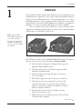
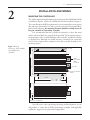
Manual
Models 1204M/05M/09M/21M
Electronic Motor Controllers
with Universal Logic Board
Curtis Instruments, Inc.
200 Kisco Avenue
Mt. Kisco, NY 10549
www.curtisinstruments.com
Read Instructions Carefully!
Specifications are subject to change without notice.
© 2012 Curtis Instruments, Inc. ® Curtis is a registered trademark of Curtis Instruments, Inc.
© The design and appearance of the products depicted herein are the copyright of Curtis Instruments, Inc.
53121 Rev A 9/12
CONTENTS
CONTENTS
1. OVERVIEW ................................................................................... 1
2. INSTALLATION AND WIRING ................................................. 3
Mounting the 1204M/05M Controller ..................................... 3
Mounting the 1209M/21M Controller ..................................... 4
Connections: High Current ...................................................... 5
Connections: Low Current........................................................ 5
Controller Wiring Configuration, with active main driver ........ 7
Controller Wiring Configuration, with active reverse input ...... 8
KSI Wiring ............................................................................... 8
Forward/Reverse Wiring............................................................ 9
Throttle Wiring ...................................................................... 10
Wiring Configuration for Pump Applications ......................... 14
Installation Checkout .............................................................. 15
3. PROGRAMMABLE PARAMETERS ........................................... 17
Voltage Parameters .................................................................. 18
Current Parameters ................................................................. 19
Speed Parameters..................................................................... 20
Throttle Input Parameters ....................................................... 21
Miscellaneous Parameters ........................................................ 23
Controller Cloning ................................................................. 24
4. MONITOR MENU ..................................................................... 25
5. DIAGNOSTICS AND TROUBLESHOOTING ........................ 26
6. MAINTENANCE ........................................................................ 30
APPENDIX A
EMC & ESD Design Considerations
APPENDIX B
Programming Devices
APPENDIX C
Controller Specifications
Curtis 1204M/05M/09M/21M Manual
iii
FIGURES / TABLES
FIGURES
fig. 1:
Curtis 1204M and 1209M electronic motor controllers ............1
fig. 2:
Mounting dimensions, Curtis 1204M/05M controllers ............3
fig. 3:
Mounting dimensions, Curtis 1209M/21M controllers .............4
fig. 4:
Standard wiring configuration, with active main driver .............7
fig. 5:
Standard wiring configuration, with active reverse input ..........8
fig. 6:
Wiring to inhibit plug braking .................................................9
fig. 7:
Wiring for mechanical reversing ..............................................10
fig. 8:
Wiring for Type 0 throttles .....................................................10
fig. 9:
Wiring for Type 1, 3, 4, and 5 throttles .................................11
fig. 10:
Wiring for Type 2 throttles ....................................................13
fig. 11:
Wiring configuration for pump applications ..........................14
fig. 12:
Effect of throttle adjustment parameters ..................................22
TABLES
iv
table 1:
High current connections .....................................................5
table 2:
Low current connections ......................................................5
table 3:
J4 connector pinout .............................................................6
table 4:
Status LED fault codes .......................................................26
table 5:
Troubleshooting chart ........................................................28
Curtis 1204M/05M/09M/21M Manual
1 — OVERVIEW
1
OVERVIEW
Curtis 1204M, 1205M, 1209M, and 1221M series motor controllers are the
form/fit/function replacements of the earlier 1204/1205/1209B/1221B controllers, with the added functionality of being programmable—via a Curtis
handheld programmer or PC programming station. This means the controllers
can be tailored to the needs of specific applications. In addition to configuration
flexibility, use of the programmer offers diagnostic and test capability.
These controllers are the ideal solution for a variety of electric vehicle
applications, including industrial trucks, personnel carriers, material handing
vehicles, light on-road vehicles, golf cars, etc.
Fig. 1 Curtis 1204M
and 1209M programmable
series motor controllers.
Except for their length, the
1204M and 1205M look
the same, as do the 1209M
and 1221M.
Like all Curtis controllers, the 1204M/05M/09M/21M models offer superior
operator control of motor drive performance. Features include:
✓ Universal logic board supports multiple throttle types and
high pedal disable (HPD) options.
✓ Environmental protection provided by rugged anodized
aluminum extruded housing.
✓ Simple mounting and wiring with push-on connectors
for control signals.
✓ Plated solid copper buses used for all power connections.
✓ Thermal protection and compensation circuit provides
constant current limit over operating range and during
under/over temperature cutback; no sudden loss of power
under any thermal conditions.
✓ Throttle fault protection circuitry disables controller
if throttle wires become open.
✓ HPD feature prevents controller operation if key is turned
on while throttle is applied.
More Features
Curtis 1204M/1205M/1209M/1221M Manual
☞
1
1 — OVERVIEW
✓ Plug braking diode internal to controller.
✓ Undervoltage cutback function protects against low battery
voltage, including low voltage caused by external loads.
✓ Easily programmable through the Curtis handheld
programmer or PC programming station.
Familiarity with your Curtis 1204M/05M/09M/21M controller will help you
install and operate it properly. We encourage you to read this manual carefully.
If you have questions, please contact the Curtis office nearest you.
2
Curtis 1204M/1205M/1209M/1221M Manual
2 — INSTALLATION & WIRING
2
INSTALLATION AND WIRING
MOUNTING THE CONTROLLER
The outline and mounting hole dimensions are shown for the 1204M and 1205M
controllers in Figure 2, and for the 1209M and 1221M controllers in Figure 3.
The controllers meet the IP54 requirements for environmental protection against
dust and water. Nevertheless, in order to prevent external corrosion and leakage
paths from developing, the mounting location should be carefully chosen to
keep the controller as clean and dry as possible.
It is recommended that the controller be fastened to a clean, flat metal
surface with four M6 bolts, using the holes provided. The mounting surface is
an integral part of the overall heatsinking of the controller, and affects its ability
to dissipate heat. Although not usually necessary, a thermal joint compound
can be used to improve heat conduction from the controller heatsink to the
mounting surface.
Fig. 2 Mounting
7.2 dia.
B+
146
dimensions, Curtis 1204M
and 1205M motor
controllers.
1204M:
22.2 ×19 ×3
1205M:
130.3
B-
25 ×19 ×3
8.5 dia.
push-on terminal,
4 plcs
133.3
173
199
M-
77
MODEL 1204M:
MODEL 1205M:
5.0
Dimensions in millimeters.
You will need to take steps during the design and development of your
end product to ensure that its EMC performance complies with applicable
regulations; suggestions are presented in Appendix A.
Curtis 1204M/1205M/1209M/1221M Manual
3
2 — INSTALLATION & WIRING
Fig. 3 Mounting
7.2 dia.
22.8 ×19 ×5
25 × 19 × 5
A2:
B+
180
dimensions, Curtis 1209M
and 1221M motor
controllers.
165
B-
8.5 dia.
push-on terminal,
4 plcs
MODEL 1209M:
MODEL 1221M:
152.4
203
229
281
5.0
M-
80
MODEL 1209M:
MODEL 1221M:
These controllers contain ESD-sensitive components. Use appropriate precautions in connecting, disconnecting, and handling the controller. See installation
suggestions in Appendix A for protecting the controller from ESD damage.
☞
C AU T I O N
Working on electrical systems is potentially dangerous. You should
protect yourself against uncontrolled operation, high current arcs, and
outgassing from lead acid batteries:
UNCONTROLLED OPERATION — Some conditions could cause the motor to
run out of control. Disconnect the motor or jack up the vehicle and get
the drive wheels off the ground before attempting any work on the motor
control circuitry.
— Batteries can supply very high power, and arcing can
occur if they are short circuited. Always open the battery circuit before
working on the motor control circuit. Wear safety glasses, and use properly
insulated tools to prevent shorts.
HIGH CURRENT ARCS
— Charging or discharging generates hydrogen gas,
which can build up in and around the batteries. Follow the battery manufacturer’s safety recommendations. Wear safety glasses.
LEAD ACID BATTERIES
4
Curtis 1204M/1205M/1209M/1221M Manual
2 — INSTALLATION & WIRING: Connections
CONNECTIONS
The controller’s connectors are all conveniently located on one end:
J1
J2
J3
B–
B+
M–
J5
A2
J4
High current connections
These controllers have four high-current busbars: B+, B-, A2, and M-. The
busbars are tin-plated solid copper.
Table 1
High Current Connections
B+
Battery+ and motor armature. (plug diode -)
B-
B-.
A2
Motor armature and field (plug diode +).
M-
Motor field (controller output).
Cables used for the battery and motor connections must be heavy enough to
carry the high current required. A minimum size of 25 mm2 (#4 AWG) is
recommended.
Connections to the controller busbars should be made with lugs suitable
for the cable used, fastened by M8 bolts and nuts. When tightening the bolts,
two opposing wrenches should be used. Failure to use the double-wrench
technique could cause undue strain to be placed on the internal connections,
and could also result in cracked seals around the busbars.
Low current connections
These controllers have five low-current connections: four 6.35 mm push-on
terminals (J1, J2, J3, and J5), and one 4-pin connector (J4).
Table 2
Low Current Connections
J1
Keyswitch.
J2
Wire 1 of 2-wire throttle; Pot High of 3-wire or ITS throttle.
J3
Wire 2 of 2-wire throttle; Pot Wiper of 3-wire throttle;
Pot Low of ITS thottle; or electronic throttle input.
J4
4-pin connector: see Table 3.
J5
Reverse signal output / main contactor coil driver.
For the control wiring, 0.75 mm2 (#18 AWG) vinyl insulated stranded wire
is recommended.
Curtis 1204M/1205M/1209M/1221M Manual
5
2 — INSTALLATION & WIRING: Connections
The mating connector for J4 is a 4-pin Molex Mini-fit Jr. or equivalent. Either
an external Status LED or a Curtis programmer can be connected to J4. The
pinout is as follows.
Table 3
4
2
1
3
J4
J4 Connector Pinout
PIN
PROGRAMMER
STATUS LED
J4-1
Data input from programmer (Rx).
Status LED enable.
J4-2
Ground.
Ground.
J4-3
Data output to programmer (Tx).
Status LED output.
J4-4
+15 V.
+15 V.
Note: When J4 is used for a Status LED, a jumper must be added between
pins J4-1 and J4-4 as shown in the basic wiring diagram (Figure 3).
6
Curtis 1204M/1205M/1209M/1221M Manual
2 — INSTALLATION & WIRING: Standard Wiring Diagrams
CONTROLLER WIRING: BASIC CONFIGURATIONS
Two basic wiring diagrams are shown; they are identical except for the wiring
at terminal J5. In the configuration in Figure 4, the main contactor driver is
active. In the configuration in Figure 5, the reverse input is active.
Wiring with active main contactor
For this option, set the Rev Input / Main Driver parameter = 2 (see
page 24), and wire the controller as shown in Figure 4.
J5 is used to drive the main contactor, which will open the battery
power in the event of a severe fault; this will help to meet safety regulations. If you wish to limit reverse speed, you will need to add a speed
reduction resistor.
Wiring with active reverse input
For this option, set the Rev Input / Main Driver parameter = 1 (see
page 24), and wire the controller as shown in Figure 5.
J5 is used as the input when the reverse direction is selected. This
simplifies the wiring for limiting reverse speed; the speed in reverse is
limited by the setting of the Rev Speed parameter. However, with this
configuration the main contactor does not open the battery power in
the event of a severe fault.
POLARITY
PROTECTION
DIODE
PEDAL
MICROSWITCH
INTERLOCKS
MAIN
Resistor Values
12V: 33 Ω, 5W
PRECHARGE RESISTOR
24V: 100 Ω, 10 W
36–48V: 250 Ω, 10W
60–72V: 250 Ω, 20W
+
A2
F
A1
–
S1
F
5kΩ THROTTLE
R
MOTOR
FIELD
R
MAIN
MOTOR
ARMATURE
F
R
REVERSE
POWER WIRING
FUSE
KEYSWITCH
FORWARD
CONTROL WIRING
FUSE
S2
STATUS
LED
J1
J2
J3
M–
B–
B+
J5
A2
J4
Fig. 4 Basic wiring diagram, Curtis 1204M/05M/09M/21M with active main contactor.
Curtis 1204M/1205M/1209M/1221M Manual
7
2 — INSTALLATION & WIRING: KSI Wiring
POLARITY
PROTECTION
DIODE
PEDAL
MICROSWITCH
INTERLOCKS
MAIN
Resistor Values
12V: 33 Ω, 5W
PRECHARGE RESISTOR
24V: 100 Ω, 10 W
36–48V: 250 Ω, 10W
60–72V: 250 Ω, 20W
A2
MOTOR
ARMATURE
F
–
S1
MOTOR
FIELD
F
5kΩ THROTTLE
R
R
F
A1
REVERSE
+
R
MAIN
POWER WIRING
FUSE
KEYSWITCH
FORWARD
CONTROL WIRING
FUSE
S2
STATUS
LED
J1
J2
J3
M–
B–
B+
J5
A2
J4
Fig. 5 Basic wiring diagram, Curtis 1204M/05M/09M/21M with active reverse input.
The throttle shown in the basic wiring diagrams is a 2-wire potentiometer.
Various types of throttles can be used; see Throttle Type parameter (page 21)
and throttle wiring (pages 10–13).
Coil suppression diodes should be used on the main and forward/reverse
contactors, as shown.
KSI Wiring
The keyswitch input (KSI) circuit includes input from the keyswitch and from
the various interlocks. The controller KSI is used to turn the controller on and
off. KSI is turned on by connecting it to battery B+. Any positive voltage greater
than about 16 volts will turn on the controller, but usually the full vehicle battery voltage is used. KSI draws up to 130 mA with the programmer connected,
and up to 70 mA without the programmer.
In its simplest form, KSI is operated by a keyswitch that turns the vehicle off and prevents unauthorized use. The keyswitch should also turn off
the main contactor and the forward/reverse contactors. This will act as a safety
feature by removing power from the motor control system when the keyswitch
is turned off.
8
Curtis 1204M/1205M/1209M/1221M Manual
2 — INSTALLATION & WIRING: Forward/Reverse Wiring
Interlocks (seat switches, battery charger interlocks, etc.) should be wired
in series so that they turn off the controller KSI and the contactors.
Forward/Reverse Wiring
With these controllers, it is essential that the field be reversed and that the
armature be connected directly to the controller’s B+ and A2 terminals,
because the plug diode inside is connected to these terminals; this is the
wiring shown in Figures 4 and 5. Some vehicles, especially those previously using older, resistor-type controllers, may reverse the motor armature rather than
the field winding. Be careful if you are replacing this type of controller.
Plug braking
Wired as shown in the basic wiring diagrams, the vehicle will plug brake if
the direction is changed with the vehicle moving and the throttle applied. The
forward/reverse switch should be in the positive feed to the contactor coils, so
that they can be turned off by the keyswitch and any interlocks. The coil of
one contactor or the other is energized to select the direction desired.
Freewheeling (wiring to inhibit plug braking)
If plug braking is not desired, the vehicle can be wired so that moving the
forward/reverse switch through neutral causes the vehicle to freewheel as long
as the throttle is applied. Plug braking can be reactivated during freewheeling
by releasing the throttle and reapplying it. The HPD option must be enabled
(programmed On) in order for this arrangement to work.
As shown in Figure 6, another set of contacts is added on the forward/reverse
switch. Therefore, a double-pole, double-throw (DPDT) center-off switch must
be used for this setup. A “hesitation switch” is recommended, to ensure the switch
is in neutral long enough to actuate HPD and inhibit plug braking.
POLARITY
PROTECTION
DIODE
INTERLOCKS
PEDAL
MICROSWITCH
F/R SWITCH
(DPDT, center off)
–
REVERSE
+
KEYSWITCH
FORWARD
FUSE
to inhibit plug braking, in
order to allow freewheeling.
MAIN
Fig. 6 Control wiring
J1
Curtis 1204M/1205M/1209M/1221M Manual
9
2 — INSTALLATION & WIRING: Throttle Wiring
Wiring for mechanical reversing switch (golf car type)
As shown in Figure 7, this type of switch mechanically interchanges the two
motor field cables by rotating a movable contact bar. The configuration shown
is typical; many variations are in use.
Fig. 7 Wiring for reversing
FUSE
with a mechanical F/R
switch arm.
+
MAIN
PRECHARGE RESISTOR
(250 Ω, 5 W)
MOTOR FIELD
S2
S1
A2
A1
MOTOR ARMATURE
–
B–
M–
B+
A2
Throttle Wiring
Ten throttle types can be used with these controllers:
Type 0 2-wire potentiometer, 0–5kΩ
Type 1 2-wire potentiometer, 5kΩ–0
Type 2 single-ended 0–5V input
Type 3 2-wire potentiometer, 4.6kΩ–0
Type 4 2-wire potentiometer, 5.5kΩ–0
Type 5 2-wire potentiometer, 1kΩ–0
Type 6 ITS input
Type 7 single-ended 6.3–10.6 V input
Type 8 single-ended 6–12 V input
Type 9 single-ended 3-wire potentiometer, 0–5kΩ
Throttle Type 0
Wiring for Type 0 throttles is simple: just connect the two wires to the J2 and J3
push-on terminals; it doesn’t matter which wire goes on which terminal. With
Type 0 throttles, resistance increases as the applied throttle is increased.
Fig. 8 Wiring for Type 0
throttles.
J1
J2
J3
Mechanical potboxes and footpedals are Type 0 throttles. It doesn’t matter which
wire goes on which terminal, and the wires can be extended as required.
10
Curtis 1204M/1205M/1209M/1221M Manual
2 — INSTALLATION & WIRING: Throttle Wiring
Some potboxes have a built-in microswitch, eliminating the need to install
a separate pedal-actuated microswitch. It is important that a pedal microswitch
be included in the circuit as shown in Figures 4 and 5 to allow the microcontroller a few milliseconds to boot up, run diagnostics and safety checks, and
then be ready in standby before receiving the throttle signal.
A potbox makes it easy to retain the vehicle’s original cable throttle pedal.
Curtis and various third-party vendors also offer self-contained footpedal units
that eliminate the need for fabricating and installing a pedal-potbox linkage.
Any potbox that can provide a nominal 0–5kΩ output will work as a Type 0
throttle input.
If a potbox is used, it must be mounted so as to allow connection between the potbox lever arm and the vehicle accelerator linkage. Use of a second
return spring on the pedal, in addition to the potbox return spring, is required
to prevent an uncontrollable full-on throttle input (which could happen if
there was a single spring, and it broke). If the self-contained potbox spring is
insufficient to return the pedal by itself, two additional pedal return springs
must be used.
It is also required that the accelerator pedal hit a mechanical stop at its
full-on position just before (≈1 mm) the potbox lever hits its own full-on stop.
This mechanical stop will prevent the potbox lever arm from bending if undue
force is put on the pedal. Protection of the potbox from water and dirt will
help avoid problems of corrosion and electrical leakage.
After the potbox has been mounted, operation of the pot can be tested
by measuring the resistance between the two wires with an ohmmeter. With
the pedal not applied, the resistance should be less than 50 ohms. As the pedal
is applied, the resistance should rise smoothly until it reaches a value between
4500 and 5500 ohms. Values below 4500 ohms may cause a reduction in
efficiency and top speed; however, you still can get top speed by lowering the
Throttle Max setting. Values above 7500 ohms indicate a defective potbox, and
will cause controller shutdown.
Throttle Types 1, 3, 4, 5
Wiring for Type 1, 3, 4, and 5 throttles is the same as for Type 0 throttles;
again, it doesn’t matter which wire goes on which terminal. With these throttles,
resistance is in an inverse relationship to applied throttle; that is, resistance
decreases as applied throttle is increased.
Fig. 9 Wiring for Type 1,
3, 4, and 5 throttles.
FASTER
5kΩ–0
4.6kΩ–0
5.5kΩ–0
1kΩ–0
Curtis 1204M/1205M/1209M/1221M Manual
J1
J2
J3
(Type 1)
(Type 3)
(Type 4)
(Type 5)
11
2 — INSTALLATION & WIRING: Throttle Wiring
Throttle Type 2
With Type 2 throttles, the controller looks for a voltage signal at J3.
Zero throttle request corresponds to 0 V and full throttle request to 5 V. A
variety of devices can be used with this throttle input type, including voltage
sources, current sources, and electronic throttles. The wiring for each is slightly
different, as shown in Figure 10, and they have varying levels of throttle fault
protection.
When a voltage source is used as a throttle, it is the responsibility of the
OEM to provide appropriate throttle fault detection. For ground-referenced
0–5V throttles, the controller will detect open breaks in the wiper input but
cannot provide full throttle fault protection.
To use a current source as a throttle, a resistor must be added to the circuit
to convert the current source value to a voltage; the resistor should be sized to
provide a 0–5V signal variation over the full current range. It is the responsibility of the OEM to provide appropriate throttle fault detection.
The Curtis ET-XXX electronic throttle contains no built-in fault detection, and the controller will detect only open wiper faults. It is the responsibility of the OEM to provide any additional throttle fault detection necessary.
For wiring other electronic throttles, consult the instructions that are provided
with the throttle.
There are many electronic footpedals on the market; for wiring, consult
the instructions that are provided with the footpedal.
Throttle Type 6
The ITS+ connects to J2, and ITS- connects to J3.
Throttle Types 7, 8
Wiring for these voltage input throttles is the same as for Type 2 throttles; the
throttle input goes to J3 and the ground return to B-.
Throttle Type 9
The Pot High input goes to J2, the Pot Wiper goes to J3, and the ground return
goes to B-. No signals to the controller’s forward and reverse inputs are required,
because the direction is determined by the wiper input value. The neutral point
will be with the wiper at 2.5 V, measured between the pot wiper input (J3) and
I/O ground return (B-). The controller will provide increasing forward speed
as the wiper input is increased from the neutral point, and increasing reverse
speed as the wiper input value is decreased from the neutral point.
When a 3-wire pot is used, the controller provides full fault protection.
12
Curtis 1204M/1205M/1209M/1221M Manual
2 — INSTALLATION & WIRING: Throttle Wiring
Fig. 10 Wiring for Type 2
Voltage Source
throttles.
+
+
-
Current Source
Curtis ET-XXX Electronic Throttle
+
–
Curtis 1204M/1205M/1209M/1221M Manual
13
2 — INSTALLATION & WIRING: Throttle Wiring; Pump Applications
Basic Wiring Configuration for Pump Applications
The 1204M-6302 controller has only three busbars; it is appropriate for use
with pump motors, wired as shown in Figure 11.
CONTROL WIRING
FUSE
POWER WIRING
FUSE
KEYSWITCH
ENABLE
INTERLOCKS
POLARITY
PROTECTION
DIODE
MAIN
MAIN
PRECHARGE RESISTOR
(250 Ω, 5 W)
+
A1
MOTOR
ARMATURE
–
5kΩ THROTTLE
A2
S1
MOTOR
FIELD
STATUS
LED
J1
J2
J3
S2
B–
B+
J5
M–
J4
Fig. 11 Basic wiring diagram, Curtis 1204M-6302 motor controller—for pump applications.
14
Curtis 1204M/1205M/1209M/1221M Manual
2 — INSTALLATION & WIRING: Installation Checkout
INSTALLATION CHECKOUT
Carefully complete the following checkout procedure before operating the
vehicle. If a step does not test correctly, refer to Section 5: Diagnostics and
Troubleshooting.
☞
Put the vehicle up on blocks to get the drive wheels off
the ground before beginning these tests.
C AU T I O N
Don’t let anyone stand in front of or behind the vehicle
during the checkout.
Make sure the keyswitch is off and the vehicle is in
neutral before beginning.
Wear safety glasses and use well-insulated tools.
A. Connect the battery. Use a voltmeter to verify that the proper voltage and
polarity appears at the battery B+ and B- terminals.
B. Check the voltage at the controller B+ and B- busbars. If your system
has a precharge resistor in parallel with the main contactor, you should see
approximately 90% of the full battery voltage. If your system does not have
a resistor, temporarily connect one (100 to 200 ohms, 5 watts, or a 100 watt
light bulb). The voltage at the controller should rise to approximately 90% of
the full battery voltage.
C. If “A” and “B” do not check out, troubleshoot the wiring connections. Do
not turn on the keyswitch until the trouble is corrected and “A” and “B”
check out.
D. With the forward/reverse switch in neutral, turn on the keyswitch. If the
motor runs without the throttle being applied, turn the keyswitch off and
recheck the wiring. If the motor does not run without the throttle applied,
proceed with the checkout. Select a direction and slowly apply the throttle; the
motor should now respond.
E. Look to see which direction the wheels are turning. If the wheels are going
the wrong way, turn everything off and interchange the motor field connections.
F. If you have HPD, check it next. Turn off the keyswitch and direction
switch. Apply the throttle, turn the keyswitch on, and then select a direction.
The motor should not run. Release the throttle and re-apply it — the motor
should now run. If the motor runs before you release the throttle, recheck the
wiring.
Curtis 1204M/1205M/1209M/1221M Manual
15
2 — INSTALLATION & WIRING: Installation Checkout
G. Take the vehicle down off the blocks and drive it in a clear area. It should
have smooth acceleration and good top speed.
H. On vehicles that are intended to plug brake, test the plug braking by driving forward at moderate speed and shifting into reverse without letting up on
the throttle. The vehicle should smoothly brake to a stop and accelerate in
reverse.
I. On vehicles that are intended to have plug braking inhibited, verify that
the maneuver in “H” produces freewheel coasting.
16
Curtis 1204M/1205M/1209M/1221M Manual
3 — PROGRAMMABLE PARAMETERS
3
PROGRAMMABLE PARAMETERS
The 1204M/05M/09M/21M controllers have a number of parameters that
can be adjusted using a Curtis programming device. These programmable
parameters allow the vehicle’s performance to be customized to fit the needs
of specific applications.
The programmable parameters are displayed in five submenus within the
Program menu (on the 1311 handheld programmer) or the Parameters menu
(on the 1313 handheld programmer or 1314 PC Programming Station).
Voltage
Battery Voltage
Undervoltage Cutback
Undervoltage Cutback Rate
Undervoltage Cutoff
Current
Main Current Limit
Plug Current Limit
Speed
Accel Rate
Quick Start
Max Speed
Rev Speed
Throttle
Throttle Type
Throttle Deadband
Throttle Max
Throttle Map
Misc
HPD
Variable Plug
Boost
Contactor Protection
Main Drop Delay
Rev Input / Main Driver
The individual parameters are presented as follows in the parameter charts:
Parameter name
as it appears in the
programmer display
Allowable range
in the
programmer’s units
⇓
⇓
Max Speed
0–100 %
Description of the parameter’s
function and, where applicable,
suggestions for setting it
⇓
Defines the maximum motor speed at full throttle, as % PWM.
Curtis 1204M/1205M/1209M/1221M Manual
17
3 — PROGRAMMABLE PARAMETERS: Voltage Parameters
VOLTAGE MENU
PARAMETER
ALLOWABLE
RANGE
Battery Voltage
1–6
Under Voltage Cutback
Under Voltage Cutback Rate
Under Voltage Cutoff
18
DESCRIPTION
Set this parameter to match the battery pack of your vehicle.
1 = 12 V
2 = 24 V
3 = 36 V
4 = 48 V
5 = 60 V
6 = 72 V.
68 – 100 %
The controller’s circuitry requires a minimum battery voltage to function
properly. When battery voltage drops, reducing the controller’s output
to the motor allows the battery to recover. The Under Voltage Cutback
parameter sets the threshold voltage below which controller output will
start to be reduced.
The programmed value is a percentage of the battery voltage.
0 – 110 A
The Under Voltage Cutback Rate determines how quickly the controller
output will be reduced when battery voltage falls below the programmed
Under Voltage Cutback threshold.
The programmed value is the amount the current will be reduced
for every 0.4 V the battery voltage decreases.
Larger values represent faster reduction of controller output.
Setting Under Voltage Cutback Rate = 0 means there will be no
undervoltage cutback.
67 – 100 %
The Under Voltage Cutoff parameter sets the voltage at which controller
output will be cut off completely.
The programmed value is a percentage of the battery voltage.
Curtis 1204M/1205M/1209M/1221M Manual
3 — PROGRAMMABLE PARAMETERS: Current Parameters
CURRENT MENU
PARAMETER
ALLOWABLE
RANGE
DESCRIPTION
Main Current Limit
50 A – rated current
The main current limit can be programmed, in 5A increments, up to the
controller’s 2-minute current rating (see model chart in Appendix C).
Plug Current Limit
50 – 250 A
Plug braking occurs when the opposite direction is selected with the
forward/reverse switch without releasing the throttle. The vehicle brakes
smoothly to a stop and then accelerates in the other direction.
The plug braking current limit is set by this parameter.
Plug braking can be either fixed or throttle-variable; see Variable
Plug parameter (page 23). During fixed plug braking, the plug braking
current is the programmed Plug Current Limit value. During variable
plug braking, the plug braking current varies with the amount of applied
throttle, from 50% to 100% of the programmed Plug Current Limit value.
Curtis 1204M/1205M/1209M/1221M Manual
19
3 — PROGRAMMABLE PARAMETERS: Speed Parameters
SPEED MENU
PARAMETER
ALLOWABLE
RANGE
DESCRIPTION
Accel Rate
0.2 – 3.0 s
The Accel Rate defines the time it takes the controller to accelerate from 0%
output to 100% output when full throttle is applied.
Larger values represent a longer acceleration time and therefore a gentler
start. For faster starts, adjust the Accel Rate to a smaller value.
Quick Start
0.2 – 3.0 s
When the throttle is moved from zero rapidly, the quick start feature is activated.
The Quick Start acceleration rate then replaces the normal acceleration rate (as
set by the Accel Rate parameter).
The Quick Start parameter can only be set to values smaller (faster) than
the programmed Accel Rate.
Max Speed
20 – 100 %
Defines the maximum requested motor speed at full forward throttle, as %
PWM. Partially-applied throttle is scaled proportionately; e.g., 40% applied
throttle corresponds to a request for 40% of the programmed Max Speed value.
Example: if Max Speed is set to 80%, a 40% applied forward throttle corresponds
to a 32% request (0.80 * 0.40 = 0.32).
Rev Speed
40 – 100 %
Defines the maximum requested motor speed at full reverse throttle, as %
PWM. Partially-applied throttle is scaled proportionately; e.g., 40% applied
throttle corresponds to a request for 40% of the programmed Max Speed value.
Example: if Max Speed is set to 80%, a 40% applied reverse throttle corresponds
to a 32% request (0.80 * 0.40 = 0.32).
The Rev Speed parameter is in effect only with the “reverse input active”
wiring configuration or with a speed reduction resistor added to the circuit.
20
Curtis 1204M/1205M/1209M/1221M Manual
3 — PROGRAMMABLE PARAMETERS: Throttle Parameters
THROTTLE MENU
PARAMETER
Throttle Type
ALLOWABLE
RANGE
0–9
DESCRIPTION
The 1204M/05M/09M/21M controllers accept a variety of throttle inputs. The
Throttle Type parameter can be programmed as follows:
0
1
2
3
4
5
6
7
8
9
Throttle Deadband
2-wire potentiometer, 0–5kΩ input
2-wire potentiometer, 5kΩ–0 input
single-ended 0–5V input
2-wire potentiometer, 4.6kΩ–0 input
2-wire potentiometer, 5.5kΩ–0 input
2-wire potentiometer, 1kΩ–0 input
ITS input
6.3–10.6 V input
6–12 V input
single-ended 3-wire potentiometer, 0–5kΩ input.
4 – 90 %
The Throttle Deadband parameter defines the neutral deadband as a percentage of the full throttle range. Increasing the Throttle Deadband setting will
increase the neutral range. This parameter is especially useful with throttle
assemblies that do not reliably return to a well-defined neutral point, because
it allows the deadband to be defined wide enough to ensure that the controller
goes into neutral when the throttle mechanism is released.
Throttle Max
10 –100 %
The Throttle Max parameter defines the percentage of throttle movement at
which 100% output is requested. Decreasing the Throttle Max setting reduces
the full stroke necessary to produce full controller output. This parameter allows reduced-range throttle assemblies to be accommodated.
Throttle Map
20 – 80 %
The Throttle Map parameter modifies the vehicle’s response to the throttle
input. Setting Throttle Map at 50% provides a linear output response to throttle
position. Values below 50% reduce the controller output at low throttle settings,
providing enhanced slow speed maneuverability. Values above 50% give the
vehicle a faster, more responsive feel at low throttle settings.
The Throttle Map value is the controller output at half throttle, as a
percentage of the Max Speed. Half throttle is the midpoint of the throttle’s active
range, which is the range from zero output (at the Deadband setting) to 100%
output (at the Throttle Max setting).
Curtis 1204M/1205M/1209M/1221M Manual
21
3 — PROGRAMMABLE PARAMETERS: Throttle Parameters
The Throttle Deadband, Throttle Max, and Throttle Map parameters work
together to condition the throttle command, as shown in Figure 12.
Fig. 12 Effect of throttle
adjustment parameters.
Deadband = 10%
Throttle Max = 80%.
THROTTLE COMMAND (percentage of Max Speed)
In the examples shown
in this figure,
Throttle Max
adjusts this endpoint.
100
MAP
Map adjusts the “knee” in
the output; this knee is at
an 80% Map setting.
90
80%
60%
80
50%
70
40%
60
20%
30%
50
40
The unshaded
area represents
the throttle’s
active range.
30
20
10
Deadband parameter
adjusts this endpoint.
0
0
20
40
60
80
100
THROTTLE POSITION (percentage of full range)
22
Curtis 1204M/1205M/1209M/1221M Manual
3 — PROGRAMMABLE PARAMETERS: Misc. Parameters
MISCELLANEOUS PARAMETERS
PARAMETER
ALLOWABLE
RANGE
DESCRIPTION
HPD
On/Off
By preventing the vehicle from being turned on with the throttle applied,
the HPD feature ensures the vehicle starts smoothly and safely. To start,
the controller must receive an input to KSI before receiving a throttle
input. In addition to providing routine smooth starts, HPD also protects
against accidental sudden starts if problems in the linkage (such as
bent parts or a broken return spring) give a throttle input signal to the
controller even with the throttle released.
When programmed On, the HPD feature is enabled. This is required
for full throttle protection.
When programmed Off, the HPD feature is not enabled.
Variable Plug
On/Off
Plug braking occurs when the opposite direction is selected with the
forward/reverse switch without releasing the throttle. The vehicle brakes
smoothly to a stop and then accelerates in the other direction.
When Variable Plug is programmed On, the plug braking current
varies with the amount of applied throttle. The range is from 50% to
100% of the programmed Plug Current Limit (see page 19).
When Variable Plug is programmed Off, plug braking is fixed at the
current set by the programmed Plug Current Limit.
Boost
On/Off
In situations where the controller detects that the motor is about to
stall, the boost feature provides a short burst of extra torque by briefly
applying a current higher than the rated current. This can be useful for
occasionally getting the vehicle out of a pothole or over an obstacle.
Setting the Boost parameter On enables the boost feature.
If the Boost parameter is set to Off, the controller’s output is limited
to its rated current.
Contactor Protection
On/Off
The Contactor Protection parameter can be used to protect the tips of
the F/R contactors and main contactor from possible damage due to high
current arcs.
If the Contactor Protection parameter is programmed On, when the
controller detects the throttle is released (within the throttle deadband) it
will immediately cut off the PWM output, and because the current is cut
off quickly the contactor tips will be opened with no high current arcs.
Similarly, when a F/R contactor is open, the controller will lock the PWM
output so that when the contactor starts to close again, there is no current
on the tips.
If programmed Off, this protection is lost. However, the PWM will
decrease at the set deceleration rate instead of abruptly, resulting in a
smoother stop—which may be desired in some applications.
Main Drop Delay
0 – 60 s
The Main Drop Delay defines the time delay before the main contactor
drops out after there has been no active throttle signal.
Setting Main Drop Delay = 0 means the main contactor never drops
out; it does not mean there is no delay.
Curtis 1204M/1205M/1209M/1221M Manual
23
3 — PROGRAMMABLE PARAMETERS: Misc. Parameters
MISCELLANEOUS PARAMETERS, continued
PARAMETER
Rev Input / Main Driver
ALLOWABLE
RANGE
0–2
DESCRIPTION
This parameter determines the signal input at the controller’s J5 terminal;
see basic wiring diagrams, Figures 4 and 5.
0 = reverse input and main driver both inactive; use this setting
if you are replacing an earlier model with no J5 terminal
and want to leave the wiring as it was.
1 = Reverse input active (see page 7 description, and Figure 5).
2 = Main driver active (see page 7 description,see Figure 4).
CLONING (for copying parameter settings to multiple controllers)
Once a controller has been programmed to the desired settings, these
settings can be transferred as a group to other controllers, thus creating a
family of “clone” controllers with identical settings. Cloning only works
between controllers with the same model number. For example, the
programmer can read all the information from a 1209M-5501 controller
and write it to other 1209M-5501 controllers; however, it cannot write
that same information to 1209M-6401 controllers.
To perform cloning with the 1311 handheld programmer, plug the
programmer into the controller that has the desired settings. Scroll down
to the Functions menu; “Settings” is the only function included here. Select
“Get settings from controller” to copy the settings into the programmer.
Plug the programmer into the controller that you want to have these
same settings, and select “Write settings to controller.”
To perform cloning with the 1313 handheld programmer or 1314
PC Programming Station, use the Programming menu.
24
Curtis 1204M/1205M/1209M/1221M Manual
4 — MONITOR MENU
4
MONITOR MENU
Through its Monitor menu, the programmer provides access to real-time data
during vehicle operation. This information is helpful during diagnostics and
troubleshooting, and also while adjusting programmable parameters.
MONITOR MENU
VARIABLE
DISPLAY
UNITS
Heatsink Temp
°C
Heatsink temperature.
Throttle
%
Throttle request, as percentage of full throttle.
Duty Cycle
%
Controller’s PWM output, as percentage
of programmed Max Speed.
Cap Voltage
V
Voltage of controller’s internal capacitor bank
at B+ busbar.
A2 Voltage
V
Voltage on controller’s A2 busbar.
Battery Voltage
V
Battery voltage.
Motor Voltage
V
Voltage between controller’s B+ and M- busbars.
DESCRIPTION
Motor Open
On/Off
Status of motor connection.
Plug Braking
On/Off
Status of plug braking feature.
Curtis 1204M/1205M/1209M/1221M Manual
25
5 — DIAGNOSTICS & TROUBLESHOOTING
5
DIAGNOSTICS AND TROUBLESHOOTING
The 1204M/05M/09M/21M controllers detect a wide variety of faults or error
conditions. Fault information can be obtained in either of two ways: (1) by
observing the fault codes issued by the external Status LEDs or (2) by reading
the display on a programmer. Because the programmer uses the same connector
as the Status LED, only one of these ways can be used at any given time.
LED DIAGNOSTICS
During normal operation, with no faults present, the Status LED flashes steadily.
If the controller detects a fault, a 2-digit fault code is flashed until the fault is
corrected. For example, code “2,3”—HPD—appears as:
¤¤ ¤¤¤
(2,3)
Table 4
LED CODES
LED off
solid on
0,1
1,1
1,2
1,3
1,4
2,1
2,2
2,3
2,4
3,1
3,2
3,3
3,4
4,1
4,2
4,3
4,4
¤
¤ ¤
¤ ¤¤
¤ ¤¤¤
¤ ¤¤¤¤
¤¤ ¤
¤¤ ¤¤
¤¤ ¤¤¤
¤¤ ¤¤¤¤
¤¤¤ ¤
¤¤¤ ¤¤
¤¤¤ ¤¤¤
¤¤¤ ¤¤¤¤
¤¤¤¤ ¤
¤¤¤¤ ¤¤
¤¤¤¤ ¤¤¤
¤¤¤¤ ¤¤¤¤
■
¤¤ ¤¤¤
(2,3)
¤¤ ¤¤¤
(2,3)
STATUS LED FAULT CODES
EXPLANATION
no power or defective controller
controller or microprocessor fault
controller operational; no known faults
EEPROM fault
MOSFET short fault
[not used]
wiring fault
under voltage cutoff
[not used]
HPD sequencing error
throttle fault
main contactor coil short / driver fault
main contactor weld fault
main contactor driver fault
main contactor DNC (missing or open)
under voltage cutback, low battery voltage
over voltage
thermal cutback, due to over/under temperature
over temperature cutoff, due to severe
overtemperature(>110°C)
Note: Only one fault is indicated at a time. Faults are not queued up.
The numerical codes are listed in the troubleshooting chart (Table 5), which
also lists effects, clear conditions, and possible causes for each fault.
26
Curtis 1204M/1205M/1209M/1221M Manual
5 — DIAGNOSTICS & TROUBLESHOOTING
PROGRAMMER DIAGNOSTICS
The programmer’s Faults menu (1311 programmer) / Diagnostics menu
(1313 programmer) displays the faults that are currently set, by name. The
programmer’s Monitor menu displays various readouts that can be helpful
during diagnostics; see Section 4.
For example, in the event of an undervoltage cutback fault, the words
Undervoltage Cutback will be displayed in the Faults/Diagnostics menu. The realtime battery voltage is displayed in the Monitor menu (“Battery Voltage”).
The programmer also can display a history of all the faults that have been
set since the history log was last cleared.
TROUBLESHOOTING
The detection of a fault causes the controller to operate in a manner that is
safe in the presence of that fault. Depending on the severity of the fault, the
response can range from reducing current to complete shutdown.
The troubleshooting chart, Table 5, provides the following information
on all the controller faults:
• fault code
• fault name as displayed on the programmer’s LCD
• the effect of the fault
• fault clear conditions
• possible causes of the fault.
Some faults can be self-cleared; for example, an undervoltage fault will clear
when the battery voltage returns to an acceptable level. Whenever a fault is
encountered and no wiring or vehicle fault can be found, shut off KSI and turn
it back on to see if the fault clears. If not, shut off KSI and remove the J-1, J-2,
J-3, and J-5 connectors. Check the connectors for corrosion or damage, clean
them if necessary, and re-insert them.
Curtis 1204M/1205M/1209M/1221M Manual
27
5 — DIAGNOSTICS & TROUBLESHOOTING
Table 5 TROUBLESHOOTING CHART
PROGRAMMER
LCD DISPLAY
LED
CODE
EFFECT OF FAULT
RECOVERY
POSSIBLE CAUSE
1,1
EE Fault
PWM output disabled.
Modify any programmable 1. EEPROM data lost or
parameter with programmer.
damaged.
2. EEPROM checksum error.
1,2
MOSFET Short Fault
PWM output disabled.
Cycle KSI.
1. MOSFET shorted.
1,4
Wiring Fault
PWM output disabled.
Cycle KSI.
1. HPD Lockout exists for more
than 10 seconds.
2,1
Under Voltage Cutoff
PWM output disabled.
Battery voltage rises above
Under Voltage Cutback
threshold.
1. Battery voltage at or below
the programmed Under Voltage
Cutoff threshold.
2,3
HPD
PWM output disabled.
Release throttle.
1. Applied throttle input >20%
when KSI is turned on.
2. Applied throttle input >20%
after clearing throttle fault.
2,4
Throttle Fault
Throttle request disabled.
Throttle input signal
within allowable limits.
1. Throttle input wire open
or shorted.
2. Defective throttle.
3. Wrong Throttle Type selected.
3,1
Coil Short/Driver Fault
PWM output and main
contactor disabled.
Check the connections and
replace the main contactor
if necessary.
1. Main contactor coil is shorted.
2. Internal driver transistor is
shorted.
3,2
Main Weld Fault
PWM output and main
contactor disabled.
1. Replace main contactor.
2. Correct the parameter
Rev Input / Main Driver.
1. Main contactor is welded.
2. Main contactor is controlled
outside, but main driver
function is active.
3,3
Main Driver Fault
PWM output and main
contactor disabled.
Replace defective controller. 1. Main contactor driver is broken.
3,4
Main Contactor DNC
PWM output disabled.
Voltage difference between
KSI and B+ busbar is less
than the main contactor
DNC threshold.
1. Main contactor did not close
(DNC).
4,1
Under Voltage Cutback Output current reduced.
Battery voltage rises above
Under Voltage Cutback
threshold.
1. Battery voltage at or below
the programmed Undervoltage
Cutback threshold.
2. Corroded battery terminal.
3. Loose battery or controller
connection.
4,2
Over Voltage
Battery voltage falls below
(Over Voltage Cutoff Over Voltage Hysteresis).
1. Battery voltage ≥ factory-set
Over Voltage Cutoff threshold.
2. Operation with charger
attached.
28
PWM output disabled.
Curtis 1204M/1205M/1209M/1221M Manual
5 — DIAGNOSTICS & TROUBLESHOOTING
Table 5 TROUBLESHOOTING CHART, continued
LED
CODE
PROGRAMMER
LCD DISPLAY
EFFECT OF FAULT
RECOVERY
POSSIBLE CAUSE
4,3
Thermal Cutback
Output current reduced.
1. Current reduced during 1. Temperature ≥Temp Cutback
overtemperature.
setpoint or ≤ -10°C.
2. Current reduced to 50% 2. Excessive load on motor or
during undertemperature.
controller.
3. Improper mounting of
controller.
4. Operation in extreme
environments.
5. Controller thermistor damaged.
4,4
Over Temperature
PWM output disabled.
Heatsink temperature
≤ 100°C.
1. Heatsink temperature exceeds
the Temperature Cutoff
threshold (110°C).
Note: Faults related to the main contactor (LED codes 3,1 / 3,2 / 3,3 / 3,4)
are detected only when the main contactor is driven by the controller—wiring
configuration shown in Figure 4, and Rev Input / Main Driver parameter = 2
(see page 24).
Curtis 1204M/1205M/1209M/1221M Manual
29
6 — MAINTENANCE
6
MAINTENANCE
There are no user serviceable parts in Curtis 1204M/05M/09M/21M controllers. No attempt should be made to open, repair, or otherwise modify the
controller. Doing so may damage the controller and will void the warranty.
It is recommended that the controller and connections be kept clean and
dry and that the controller’s fault history file be checked and cleared periodically.
CLEANING
☞
C AU T I O N
Periodically cleaning the controller exterior will help protect it against corrosion
and possible electrical control problems created by dirt, grime, and chemicals
that are part of the operating environment and that normally exist in battery
powered systems.
When working around any battery powered system, proper safety
precautions should be taken. These include, but are not limited to: proper
training, wearing eye protection, and avoiding loose clothing and jewelry.
Use the following cleaning procedure for routine maintenance. Never use
a high pressure washer to clean the controller.
1. Remove power by disconnecting the battery.
2. Discharge the capacitors in the controller by connecting a load
(such as a contactor coil) across the controller’s B+ and Bterminals.
3. Remove any dirt or corrosion from the power and signal
connector areas. The controller should be wiped clean with a
moist rag. Dry it before reconnecting the battery.
4. Make sure the connections are tight.
DIAGNOSTIC HISTORY
The Curtis programming devices can be used to access the controller’s fault
history file, via the Faults/Diagnostics menu. The programmer will read out
all the faults the controller has experienced since the last time the fault history
file was cleared. Faults such as contactor faults may be the result of loose wires;
contactor wiring should be carefully checked. Faults such as overtemperature
may be caused by operator habits or by overloading.
After a problem has been diagnosed and corrected, it is a good idea to
clear the fault history file. This allows the controller to accumulate a new file
of faults. By checking the new fault history file at a later date, you can readily
determine whether the problem was indeed fixed.
30
Curtis 1204M/1205M/1209M/1221M Manual
APPENDIX A: EMC & ESD DESIGN CONSIDERATIONS
APPENDIX A
VEHICLE DESIGN CONSIDERATIONS
REGARDING ELECTROMAGNETIC COMPATIBILITY (EMC)
AND ELECTROSTATIC DISCHARGE (ESD)
ELECTROMAGNETIC COMPATIBILITY (EMC)
Electromagnetic compatibility (EMC) encompasses two areas: emissions and
immunity. Emissions are radio frequency (RF) energy generated by a product.
This energy has the potential to interfere with communications systems such
as radio, television, cellular phones, dispatching, aircraft, etc. Immunity is the
ability of a product to operate normally in the presence of RF energy.
EMC is ultimately a system design issue. Part of the EMC performance
is designed into or inherent in each component; another part is designed into
or inherent in end product characteristics such as shielding, wiring, and layout;
and, finally, a portion is a function of the interactions between all these parts.
The design techniques presented below can enhance EMC performance in
products that use Curtis motor controllers.
Emissions
Signals with high frequency content can produce significant emissions if connected to a large enough radiating area (created by long wires spaced far apart).
Contactor drivers and the motor drive output from Curtis controllers can
contribute to RF emissions. Both types of output are pulse width modulated
square waves with fast rise and fall times that are rich in harmonics. (Note:
contactor drivers that are not modulated will not contribute to emissions.)
The impact of these switching waveforms can be minimized by making the
wires from the controller to the contactor or motor as short as possible and by
placing the wires near each other (bundle contactor wires with Coil Return;
bundle motor wires separately).
For applications requiring very low emissions, the solution may involve
enclosing the controller, interconnect wires, contactors, and motor together in
one shielded box. Emissions can also couple to battery supply leads and throttle
circuit wires outside the box, so ferrite beads near the controller may also be
required on these unshielded wires in some applications. It is best to keep the
noisy signals as far as possible from sensitive wires.
Immunity
Immunity to radiated electric fields can be improved either by reducing overall
circuit sensitivity or by keeping undesired signals away from this circuitry. The
controller circuitry itself cannot be made less sensitive, since it must accurately
detect and process low level signals from sensors such as the throttle potentiometer. Thus immunity is generally achieved by preventing the external RF
energy from coupling into sensitive circuitry. This RF energy can get into the
controller circuitry via conducted paths and radiated paths.
Curtis 1204M/05M/09M/21M Manual
A-1
APPENDIX A: EMC & ESD DESIGN CONSIDERATIONS
Conducted paths are created by the wires connected to the controller.
These wires act as antennas and the amount of RF energy coupled into them
is generally proportional to their length. The RF voltages and currents induced
in each wire are applied to the controller pin to which the wire is connected.
Curtis controllers include bypass capacitors on the printed circuit board’s
throttle wires to reduce the impact of this RF energy on the internal circuitry.
In some applications, additional filtering in the form of ferrite beads may also
be required on various wires to achieve desired performance levels.
Radiated paths are created when the controller circuitry is immersed in
an external field. This coupling can be reduced by placing the controller as far
as possible from the noise source or by enclosing the controller in a metal box.
Some Curtis controllers are enclosed by a heatsink that also provides shielding
around the controller circuitry, while others are partially shielded or unshielded.
In some applications, the vehicle designer will need to mount the controller
within a shielded box on the end product. The box can be constructed of just
about any metal, although steel and aluminum are most commonly used.
Most coated plastics do not provide good shielding because the coatings
are not true metals, but rather a mixture of small metal particles in a non-conductive binder. These relatively isolated particles may appear to be good based
on a dc resistance measurement but do not provide adequate electron mobility
to yield good shielding effectiveness. Electroless plating of plastic will yield a
true metal and can thus be effective as an RF shield, but it is usually more
expensive than the coatings.
A contiguous metal enclosure without any holes or seams, known as a
Faraday cage, provides the best shielding for the given material and frequency.
When a hole or holes are added, RF currents flowing on the outside surface of
the shield must take a longer path to get around the hole than if the surface
was contiguous. As more “bending” is required of these currents, more energy
is coupled to the inside surface, and thus the shielding effectiveness is reduced.
The reduction in shielding is a function of the longest linear dimension of a
hole rather than the area. This concept is often applied where ventilation is
necessary, in which case many small holes are preferable to a few larger ones.
Applying this same concept to seams or joints between adjacent pieces or
segments of a shielded enclosure, it is important to minimize the open length
of these seams. Seam length is the distance between points where good ohmic
contact is made. This contact can be provided by solder, welds, or pressure
contact. If pressure contact is used, attention must be paid to the corrosion
characteristics of the shield material and any corrosion-resistant processes applied
to the base material. If the ohmic contact itself is not continuous, the shielding
effectiveness can be maximized by making the joints between adjacent pieces
overlapping rather than abutted.
The shielding effectiveness of an enclosure is further reduced when a wire
passes through a hole in the enclosure; RF energy on the wire from an external
field is re-radiated into the interior of the enclosure. This coupling mechanism
can be reduced by filtering the wire where it passes through the shield boundary.
A-2
Curtis 1204M/05M/09M/21M Manual
APPENDIX A: EMC & ESD DESIGN CONSIDERATIONS
Given the safety considerations involved in connecting electrical components
to the chassis or frame in battery powered vehicles, such filtering will usually
consist of a series inductor (or ferrite bead) rather than a shunt capacitor. If a
capacitor is used, it must have a voltage rating and leakage characteristics that
will allow the end product to meet applicable safety regulations.
The B+ (and B-, if applicable) wires that supply power to a control panel
should be bundled with the other control wires to the panel so that all these
wires are routed together. If the wires to the control panel are routed separately,
a larger loop area is formed. Larger loop areas produce more efficient antennas
which will result in decreased immunity performance.
Keep all low power I/O separate from the motor and battery leads. When
this is not possible, cross them at right angles.
ELECTROSTATIC DISCHARGE (ESD)
Curtis motor controllers contain ESD-sensitive components, and it is therefore
necessary to protect them from ESD (electrostatic discharge) damage. Most
of these control lines have protection for moderate ESD events, but must be
protected from damage if higher levels exist in a particular application.
ESD immunity is achieved either by providing sufficient distance between conductors and the ESD source so that a discharge will not occur, or by
providing an intentional path for the discharge current such that the circuit
is isolated from the electric and magnetic fields produced by the discharge. In
general the guidelines presented above for increasing radiated immunity will
also provide increased ESD immunity.
It is usually easier to prevent the discharge from occurring than to divert
the current path. A fundamental technique for ESD prevention is to provide
adequately thick insulation between all metal conductors and the outside environment so that the voltage gradient does not exceed the threshold required for
a discharge to occur. If the current diversion approach is used, all exposed metal
components must be grounded. The shielded enclosure, if properly grounded,
can be used to divert the discharge current; it should be noted that the location of holes and seams can have a significant impact on ESD suppression. If
the enclosure is not grounded, the path of the discharge current becomes more
complex and less predictable, especially if holes and seams are involved. Some
experimentation may be required to optimize the selection and placement of
holes, wires, and grounding paths. Careful attention must be paid to the control
panel design so that it can tolerate a static discharge.
MOV, transorbs, or other devices can be placed between B- and offending
wires, plates, and touch points if ESD shock cannot be otherwise avoided.
Curtis 1204M/05M/09M/21M Manual
A-3
APPENDIX B: PROGRAMMING DEVICES
APPENDIX B
PROGRAMMING DEVICES
Curtis programmers provide programming, diagnostic, and test capabilities
for the 1204M/05M/09M/21M controllers. The power for operating the programmer is supplied by the host controller via a 4-pin connector. When the
programmer powers up, it gathers information from the controller.
Two types of programming devices are available: the PC Programming
Station and the handheld programmer. The Programming Station has the
advantage of a large, easily read screen; on the other hand, the handheld programmer has the advantage of being more portable and hence convenient for
making adjustments in the field.
Both programmers are available in User, Service, Dealer, and OEM versions. Each programmer can perform the actions available at its own level and
the levels below that—a User-access programmer can operate at only the User
level, whereas an OEM programmer has full access.
PC PROGRAMMING STATION (1314)
The Programming Station is an MS-Windows 32-bit application that runs on
a standard Windows PC. Instructions for using the Programming Station are
included with the software.
HANDHELD PROGRAMMER (1311, 1313)
The 1313 handheld programmer is functionally equivalent to the PC Programming Station. The 1311 is an earlier model with fewer functions. Instructions
are provided in the 1311 and 1313 manuals.
PROGRAMMER FUNCTIONS
Programmer functions include:
Parameter adjustment — provides access to the individual programmable pa-
rameters.
Monitoring — presents real-time values during vehicle operation; these include
all inputs and outputs.
Diagnostics and troubleshooting — presents diagnostic information, and also a
means to clear the fault history file.
Cloning — allows you to copy customized parameter settings files.
Programming — allows you to update the system software (not available on
the 1311).
Favorites — allows you to create shortcuts to your frequently-used adjustable
parameters and monitor variables (not available on the 1311).
B-1
Curtis 1204M/05M/09M/21M Manual
APPENDIX C: SPECIFICATIONS
APPENDIX C
SPECIFICATIONS: 1204M/05M/09M/21M CONTROLLERS
Nominal input voltage
PWM operating frequency
Electrical isolation to heatsink (min.)
Model specific (see below): 24 – 36 V, 36 – 48 V, 48 – 72 V, 60–72 V
15.6 kHz
24 – 36 V and 36 – 48 V models: 500 VAC
48 – 72 V and 60 – 72 V models: 1000 VAC
KSI input current (no contactors engaged) 70 mA without programmer; 130 mA with programmer
Logic input current
< 2 mA
Status LED output current (max.)
< 2 mA
Throttle types
2-wire rheostats: 0–5kΩ, 5kΩ–0, 1kΩ–0, 4.6kΩ–0, 5.5kΩ–0
Voltage throttles: 0–5V, 6.3 –10.6 V, 6 –12 V
ITS throttle
3-wire potentiometer: 0–5kΩ
Operating ambient temperature range
Storage ambient temperature range
-40°C to 50°C
-40°C to 85°C
Package environmental rating
ISTA 2A; electronics sealed to IP54
Dimensions (L× W×H), Weight
1204M: 173 × 146 × 77 mm, 2.3 kg
1205M: 199 × 146 × 77 mm, 2.7 kg
1209M: 229 × 180 × 80 mm, 3.8 kg
1221M: 281 × 180 × 80 mm, 4.9 kg
Regulatory compliance
Designed to the requirements of EN 12895 and EN 61000.
Note: Regulatory compliance of the complete vehicle system
with the controller installed is the responsibility of the OEM.
MODEL CHART
CURRENT RATING
MODEL
NUMBER
NOMINAL BATTERY
VOLTAGE
(V)
2 MINUTE
(A)
5 MINUTE
(A)
1 HOUR
(A)
1204M-4201
24 – 36
275
200
125
1204M-6301
48 – 72
325
225
140
1204M-6302 *
48 – 72
325
225
140
1205M-4601
24 – 36
400
275
175
1205M-5603
36 – 48
500 **
350
200
1205M-6B403
60 – 72
400 **
275
175
1209M-5501
36 – 48
450
300
200
1209M-6401
48 – 72
400
275
175
1221M-6701
48 – 72
550
375
225
* This model has no A2 busbar.
** 1 minute rating.
Note: Current rating tests conducted with controller mounted to 1/8"×12"×12" aluminum plate;
continuous 1.34 m/s airflow applied perpendicular to back of plate;
ambient air temperature held near 25°C.
Curtis 1204M/05M/09M/21M Manual
C-1