1
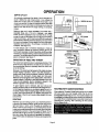
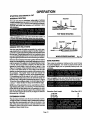
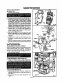
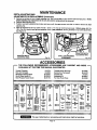
•
r
i
ii
OWNER'S
MANUAL
MODEL NO.
315.174730
CAUTION:
Read Rules for
Safe Operation
and All Instructions Carefully
CRn TSMn
Electronic Router
Double Insulated
Warranty
Introduction
f
Thank You for Buying
Craftsman Tools
Operation
Maintenance
Repair Parts
Soldonly by
SEARS, ROEBUCKAND CO., Hoffman Estates, IL 60179
612547-817
3-95
Printed In U.S.A.
FULL ONE YEAR WARRANTY ON CRAFTSMAN ELECTRONIC ROUTER
I
If this CraftsmanElectronicRouter fails to give completesatisfactionwithin one year from the date of purchase
RETURN IT TO THE NEAREST SEARS SERVICECENTER / DEPARTMENT THROUGHOUT THE UNITED
STATES and Sears willrepair it, free of charge.
Ifthisrouterisusedforcommercialor rentalpurposesthiswarrantyappliesforonly90 daysfromthedate ofpurchase.
Thiswarrantygivesyou specificlegalrights,and you may also have otherrightswhichvary fromstate to state.
SEARS, ROEBUCKAND CO.
DEPT. 817WA
HOFFMAN ESTATES, IL 60179
INTRODUCTION
DOUBLE INSULATION is a concept in safety, in electric
powertools, whicheliminatesthe need for the usual three
wire groundedpowercord and groundedsupply system.
Whereverthere is electriccurrent in the toolthere are two
completesets of insulationto protectthe user.All exposed
metal partsare isolatedfrom internalmetal motorcomponentswithprotectinginsulation.
IMPORTANT - Servicingof a tool with double insulation
requiresextreme care and knowledgeof the system and
shouldbe performedonlyby a qualifiedservice technician.
For service we suggestyou returnthe toolto your nearest
Sears Store for repair.Always use originalfactory replacement parts when servicing.
RULES FOR SAFE OPERATION
READ ALL INSTRUCTIONS
1. KNOW YOUR POWER TOOL - Read owner's
manual carefully. Learn its applications and limitations as well as the specific potential hazards related to this tool.
2. GUARD AGAINST ELECTRICAL SHOCK BY
PREVENTING
BODY
CONTACT
WITH
GROUNDED SURFACES. For example: Pipes,
radiators, ranges, refrigerator enclosures.
3. KEEP GUARDS IN PLACE and In working order.
4. KEEP WORK AREA CLEAN. Cluttered areas and
benches invite accidents.
5. AVOID DANGEROUS ENVIRONMENT, Don't use
6.
7.
8.
9.
power tool in damp or wet locations or expose to
rain. Keep work area well lit.
KEEP CHILDREN AND VISITORS AWAY. All visitors should wear safety glasses and be kept a safe
distancefrom work area. Do not let visitorscontact
tool or extension cord.
STORE IDLE TOOLS. When not in use toolsshould
be stored in a dry, high or locked-up place - out of
the reach of children.
DON'T FORCE TOOL. It will do the job better and
safer at the rate for which it was designed.
USE RIGHT TOOL. Don't force small tool or attachment to do the job of a heavy duty tool. Don't
use tool for purpose not intended - for example -
10.
11.
12.
13.
14.
15.
16.
17.
Page 2
Don't use a circular saw for cutting tree limbs or
logs.
WEAR PROPER APPAREL. No loose clothing or
jewelry to get caught in moving parts. Rubber gloves
and non-skid footwear are recommended when
working outdoors. Also, wear protective hair covering to contain long hair and keep it from being
drawn into air vents.
ALWAYS WEAR SAFETY GLASSES. Everyday
eyeglasses have only impact-resistantlenses; they
are NOT safety glasses.
PROTECT YOUR LUNGS. Wear a face or dust
mask if cutting operation is dusty.
PROTECT YOUR HEARING. Wear hearing protection during extended periods of operation.
DON'T ABUSE CORD. Never carry tool by cord or
yank it to disconnect from receptacle. Keep cord
from heat, oll and sharp edges.
SECURE WORK. Use clamps or a vise to hold
work. Both hands are needed to operate the tool.
DON'T OVERREACH. Keep proper footing and
balance at all times. Do not use on a ladder or
unstable support.
MAINTAIN TOOLS WITH CARE. Keep tools sharp
at all times, and clean for best and safest performance. Follow instructions for lubricating and
changing accessories.
RULES FOR SAFE OPERATION
(Continued)
18. DISCONNECT TOOLS. When not in use, before
servicing, or when changing attachments, blades,
bits, cutters, etc., all tools should be disconnected
from power supply.
19. REMOVE ADJUSTING KEYS AND WRENCHES.
Form habit of checking to see that keys and adjusting wrenches are removed from tool before turning
it on.
20. AVOID ACCIDENTAL STARTING. Don't carry
plugged-in tools with finger on switch. Be sure
switch Is off when plugging in.
21. MAKE SURE YOUR EXTENSION CORD IS IN
GOOD CONDITION. When using an extension
cord, be sure to use one heavy enough to carry the
current your product will draw. An undersized cord
will cause a drop in line voltage resultingin loss of
power and overheating. A wire gage size (A.W.G.)
of at least 14 is recommended for an extension
cord 100 feet or less in length. A cord exceeding
100 feet is not recommended. If in doubt, use the
next heavier gage. The smaller the gage number,
the heavier the cord.
22. OUTDOOR USE EXTENSION CORDS. When tool
is used outdoors, use only extension cords suitable for use outdoors. Outdoor appi'ovedcordsare
marked with the suffix W-A, for example - SJTW-A
or SJOW-A.
23. KEEP CUTTERS CLEAN AND SHARP. Sharp
cutters minimize stalling and kickback.
24, KEEP HANDS AWAY FROM CUTTING AREA.
Keep hands away from cutters. Do not reach underneath work while cutter is rotating. Do not attempt to remove material while cutter is rotating.
25. NEVER USE IN AN EXPLOSIVE ATMOSPHERE.
Normal sparking of the motor could ignite fumes.
26. INSPECT TOOL CORDS PERIODICALLY and if
damaged, have repaired at your nearest Sears
Repair Center. Stay constantly aware of cord location.
27. INSPECT EXTENSION CORDS PERIODICALLY
and replace if damaged.
28. KEEP HANDLES DRY, CLEAN, AND FREE
FROM OIL AND GREASE. Always use a clean
cloth when cleaning. Never use brakq fluids, gasoline, petroleum-based products or any strong solvents to clean your tool.
29. STAY ALERT. Watch what you are doing and use
common sense. Do not operate tool when you are
tired. Do not rush.
30. CHECK DAMAGED PARTS. Before further use of
the tool, a guard or other part that is damaged
shouldbe carefully checked to determine that it will
operate properly and perform its intended function.
Check for alignment of moving pads, binding of
moving parts, breakage of parts, mounting, and
any other conditions that may affect its operation.
A guard or other part that is damaged should be
propedy repaired or replaced by an authorized
service center unless indicated elsewhere in this
instructionmanual.
31. DO NOT USE TOOL IF SWITCH DOES NOT
TURN IT ON AND OFF. Have defective switches
replaced by an authorized service center.
32. Inspectfor and remove all nails from lumber before
routing.
33. DO NOT USE TOOL UNDER "BROWN-OUT" OR
OTHER LOW VOLTAGE CONDITIONS. Also, do
not use with any device that could cause the power
,
supply voltage to change.
34. DRUGS, ALCOHOL, MEDICATION. Do not operate tool while under the influence of drugs, alcohol,
or any medication.
35. WHEN SERVICING USE ONLY IDENTICAL
CRAFTSMAN REPLACEMENT PARTS.
36. POLARIZED PLUGS. To reduce the risk of electric
shock, this tool has a polarized plug (one blade is
wider than the other). This plug will fit in a polarized
outletonlyone way. If the plug does not fit fully in the
outlet, reverse the plug. If it still does not fit, contact
a qualified electricianto install the proper outlet. Do
not change the plug in any way.
37. SAVE THESE INSTRUCTIONS. Review them frequently and use them to instruct others who may
use this tool. If you loan someone this tool, loan
them these instructionsalso.
Illl
ll
IIIII
=lllll I
,llll
I
I,I
The operation of any router can result In foreign objects being thrown Into your eyes, which can
result In severe eye damage. Before beginning powertool operation, always wear safety goggles
or safety glasses with side shields and a full face shield when needed. We recommend Wide
Vision Safety Mask for use over eyeglasses or atandard safety glasses with side shields,
!
|
|
i
available at Sears Reta!!Stores.
J
Page 3
OPERATION
Yourelectronicrouterisa versatilewoodworldngiool whichwillgiveyou years oftrouble-freeperformance. Itis engineered
withthe professionalin mind, but its ease of operationallowsthe amateurto producework whichis beautifu|and precise.
Yournew routerhas advancedelectronicfeatures whichare designedto assistyou In gettingthe maximumuse from your
router. Bymakingproperspeed selections,yourroutercan be adjustedto yourspecfic routingneeds. Thiseliminatesmuch
ofthe guessworkpreviouslyneededto performa givenjob. Boththe experiencedand inexperiencedrouterusers benefit,
obtainingprofessionallike resultswith fewer job errors.
The electronicfeatureof your router introducesthe flexibility of adjustingthe motorspeed to the requiredjob conditions.
Speed can be set accordingtothe approximatecutterdiameteryou will be usingand to the hardnessof the matedal being
cut. Also,the bestcutsare made whenthe cutterisfed through the materialatthe properrate. When possible,you should
make practicecutson a scrap pieceof woodto get a "feel"of howfast to "feed=your router.
KNOW YOUR ELECTRONIC
ROUTER
Beforeattemptingto useyourrouter,familiarize yourselfwithall operatingfeatures and safety requirements.See Figure 1.
Featuresincludeelectronicfeedback switch;easily operateddepthof cutadjustment mechanism;depthstoprings;spindle
lock;"lock-on"switch;variable speed controlselector;speed selectionchart; dustpick-up;and wrenchstoragearea.
WRENCH
STORAGE AREA
BLOWER
EXHAUST
WRENCH
DUST BAG
POWER
HANDLE
SPINDLE
SWITCH
TRIGGER
DEPTH
ADJUS_NG
RING
SPEED
SELECTION
CHART
HANDLE
"LOCK-ON"
BUTTON
LEVER
DEPTH
STOP RINGS
COLLET NUT
SUBBASE
VARIABLE SPEED_
CONTROL SELECTOR
ATTACH DUST
CHIP SHIELD
TO BLOWER EXHAUST
Fig. I
II
"LOCK-ON"
BUTTON
The switchof your routeris equippedwith a "lock-on"feature whichis convenientwhen operatingfor extended periodsof
time. To lockon, depressthe trigger,pushin the lock buttonlocatedon the side of the handle,then while holdingthe lock
buttonpushedin, releasethe trigger.To release the lock,depressthe triggerand release it. See Figure 1.
VARIABLE
SPEED
Your routerhasa variablespeed controlselectordesignedto allowoperatorcontrolofspeed and torque limits. See Figure
1. To increasethespeed andtorqueofyourrouter,turnthevariablespeedcontrolselector to a highersetting.Turn toa lower
settingtodecreasespeed and torque.NOTE: Ifyou do notwantto usethevariablespeed controlselector,turntothe highest
possiblesetting,and the feature willnot be active.
Page 4
OPERATION
WRENCH
STORAGE
AREA
CHIP SHIELD
Your routerhas a wrench storagearea locatedon the top
end cap portionof the motor housing. When installingor
removingcuttersremove the wrenchfrom itsstoragearea.
Properstorageof wrench when not in use willhelpreduce
the possiblilityof losingwrench. See Figure 1.
INSTALLING/REMOVING
See Figure2.
Clear plasticchipshieldsare installedon the base of your
routerfor protectionagainstflyingdust and chips. The chip
shieldsare designedto fitthe frontand rear openingsof the
routerbase. See Figure1. If necessaryto remove,squeeze
tabs on each end and pull outward.To replace, squeeze
tabs at each end, fit into the opening,then release. FOR
YOUR PROTECTION DO NOT USE ROUTER WITHOUT
CHIP SHIELDS PROPERLY IN PLACE.
CUTTERS
1. UNPLUG YOUR ROUTER.
CUTTER
TURN TO ACTIVATE
_
COLLET NUT
2. Removedust bag from muter.
3. Removeone ofthe clearplasticchipshieldsfromrouter.
To remove,press on tabs and pull outward.
4. A spindle lock is located on the front of the motor
housing.See Figure 1. To activate lock, pushspindle
lockin and slideinto lockposition.
TO TIGHTEN =::_..'__=,,__"
.
Place yourmuter upside downon table,then turncollet
nut with wrench until lock mechanismInterlocks.See
Figure2. NOTE: Spindle lock is spdng loadedand will
snapintopositionwhen lockmechanisminterlocks.
TO LOOSEN
Fig. 2
DUST BAG ASSEMBLY
See Figure 1.
Do not connect router to power supply before Installing
duet beg or connecting it to • dust collection system.
6. Remove cuttersby tuming collet nut counterclockwise
enough to allow cutter to slip easily from collet. See
Figure2. The collaris machinedto precisiontolerances
to fit cutterswith 114in. diametershank size.
7. Withyourmuter stillupsidedownon table, insertshank
of cutterintocollet. The shankof your cuttershouldbe
closeto but not touchingbottomofcollet.
TO INSTALL BAG: ,
8. Tightenthecolletnut securelybyturningclockwisewith
The dustbag ehouldbe installedby slippingit witha twisting
the wrenchprovided. See Figure 2. Put spindlelock
moUonoverthe blowerexhaust.The bag shouldbe installed
back in unlock position. Otherwise, the interlocking
withthe zipperdownwhenrouteris in updghtposition.
mechanismofthe spindlelockwill not letyou turnyour
The bag shouldbe emptiedwhen half full.
muter on.
TO EMPTY BAG:
9. Installdust bag.
Remove bag from router,open zipper and shake out dust.
Occasionallyturn the dust bag inside out and brush the
accumulationof dust from the inside of the bag. This will
permitthe air to flow throughthe bag better.
Page5
OPERATION
DEPTH OF CUT ADJUSTMENTS
See Figures3 and 4.
We recommendthat cutsbe madeat a depthnot exceeding
118in.andthatseveralpassesbe madetoreachdepthsofcut
greaterthan 1/8 in.
1. UNPLUG YOUR ROUTER.
'
2. Place your router on a flat surface, unlock clamping
lever, and adjust until cutter is inside subbase. See
Figure3.
3. Turn the depth adjustingring untiltip of cutter touches
flatsurface. See Figure4.
4. Positionyourrouterso thatthe cuttercan extend below
the subbasefor desireddepthsetting.
5. Turnthe depthadjustingringtoobtainthedesireddepth
of cut. The distancethe cutter movescan be read on
the depthadjustingring. Use referencepoint on motor
housingto measure depth of cut. Each mark on the
depthadjustingringindicates1/64 inchchangein depth
setting.
6. Lock clampinglever, securing depth adjustingring to
motorhousingand base.
CLAMPING
LEVER
11641N. DEPTH
SETTINGS
DEPTH
ADJUSTING
RING
Fig. 3
DEPTH STOP RINGS
See Figures5 and 6.
Yourrouteris equippedwith depthstop ringsthat will allow
you to set positivestops for operating your router at two
desireddepthsofcut.
1. Release depthstoprings. To release:graspdepth stop
ringtabwithyourthumband indexfinger,and pull away
from routeras shownby the arrow. See Figure 5.
2. Usingdepth adjustingring, set cutter at lowest desired
depthofcut. Lockclampinglever.Positionbottomdepth
stopring againstdepthadjustingdng. Hold depth stop
ringagainstdepthadjustingringand lock. See Figure6.
Note: Depthstopring ends snap togetherto lock.
3. Unlockclampinglever and movedepthadjustingringto
setcutterat seconddesireddepthofcut. Lockclamping
lever,Positiontopdepthstopringagainstdepthadjusting
ring. Hold depthstop ring againstdepth adjusting ring
and lock.See Figure6. Note: Depthstopringendssnap
togetherto lock.
Depthstopringswillnowprovidea positivestopallowingyou
to operateyour routerat two cutterdepths.
Page 6
BASE,
CUTTER _Fig.
4
OPERATION
PRACTICE
BEFORE
ACTUAL
USE
See Figure7.
We suggestthatyou practicewiththe variablespeedfeature
of yourrouter beforeinstallinga cutter and makingcuts in
wood.CHECK THE FOLLOWING BEFORE CONNECTING
ROUTER TO POWER SUPPLY:
1. Make sure power supply le 120 volts, 60 Hz, AC only.
2. Make sure the spindlelookis in the unlockedposition.
3. Make sure thetriggeris not in the "lock-on"position.
4. Makesure there is not a cutterin the collet,
5. Make surethe colletdoes not extendbelowthe subbase.
6. Choosethedesiredspeed fromthespeed selectionchart.
See Figure 7.
7. Turn the variable speed controlselectorto the desired
setting.
8. Plugyour routerinto powersupplysource.
9. Graspyour routerfirmlywith both handsand turnon.
DEPTH
RING
ROUTING
See Figure8.
Forease of operationand maintainingpropercontrol,your
routerhas twohandles,one on eachside ofthe muterbase.
When using your router hold it firmlywith both hands as
shownin figure8. Turn muter on and letmotorbuildto itsfull
speed, then graduallyfeed cutter into workpiece.Remain
alertand watchwhatyou are doing. DO NOT operaterouter
whenfatigued.
ELECTRICAL
CONNECTION
Yourrouterhas a precisionbuiltelectricmotor. It shouldbe
connectedto a power supply that is 120 volt=, 60 Hz, AC
only(normal household current). Do not operatethistool
on direct current (DC). A voltage drop of more than 10
percentwill causea loss of power and overheating.If your
tooldoes not operatewhen pluggedintoan outlet,doublecheckthe power supply.
HELPFUL
POWER
HANDLE
TOINCREASE
SPEED
HINTS
/
/
/
/
Always clampworkpiecesecurelybeforemuting.
A safe operatoris one who thinksahead.
Alwayswear eye protectionwhen routing.
Make set-up adjustments carefully.Then double
check. Measuretwice and cut once.
/ Keep cuttersclean and propertysharpened.
_/ Don't let familiarity make you careless.
/ Study all safety rules and do thejob safely.
/ NEVER placeyour hands in jeopardy.
/
i/
/
i/
/
TO DECREASE
SPEED
Make certainclamps can't loosenwhilein use.
Test difficultset-upson scrap---Don'twastelumber.
Plan each operationbeforeyou begin.
Clean your router frequently, This will provide
smootheroperationofdepthadjustingringandclampinglever areas. Shake muter or blowwith an air jet
to removesawdust build-up.
THINK SAFETY BY THINKING AHEAD.
Page 7
VARIABLE SPEED
CONTROL SELECTOR
Fig. 7
OPERATION
i
PROPER
FEEDING
The right feed is neither too fast nor too slow. It is the rate at
which the bit is being advanced firmly and surely to produce
a continuous spiral of uniform chips -- without hogging into
the wood to make large individual chips or, on the other hand,
to create only sawdust. If you are making a small diameter,
shallow groove in soft, dry wood, the proper feed may be
about as fast as you can travel your router along your guide
line. On the other hand, if the bit is a large one, the cut isdeep
or the wood is hard to cut, the proper feed may be a very slow
one. Then, again, a cross-grain cut may require a slower pace
than an identical with grain cut in the same workplece.
TOO FAST
There is no fixed rle. You will learn by expedence.,,
by
listening to the muter motor and by feeling the progress of
each cut. If at all possible, always test a cut on a scrap piece
of the workpiece wood, beforehand.
SPEED SELECTION
In general, if the material being cut is hard, the cutter size is
large, or the depth of cut is deep (maximum 1/8 in.), then your
router shouldbe run at slower speeds. When these situations
exist, turn the variable speed control selector until the desired
speed is reached. NOTE: Carbide cutters cut at higher
speeds than steel cutters and should be used when cuffing
very hard materials.
RATE OF FEED
IMPORTANT:The whole"secret" of professionalroutingand
edgeshapingliesin makinga carefulset-upfor the cuttobe
made and in selectingthe properrate of feed.
FORCEFEEDING
Clean, smoothroutingand edge shapingcan be done only
when the bit is revolvingat a relativelyhigh speed and is
takingverysmallbitestoproducetiny,cleanlyseveredchips.
If yourrouteris forced to move forward too fast, the RPM of
the bit becomesslowerthan normalin relationto itsforward
movement.As a result,the bit must take bigger bites as it
revolves."Biggerbites"mean biggerchips, and a rougher
finish. Biggerchips also require more power, whichcould
resultin the routermotorbecomingoverloaded.
Underextremeforce-feeding conditionsthe relativeRPM of
the bit can becomeso slow--and the bites it has tp take so
large--thatchipswillbe partiallyknockedoff(ratherthanfully
cutoff),withresultingsplinteringandgougingoftheworkpiece.
See Figure9.
Your Craftsman Router is an extremely high-speed tool
(25,000 RPM no-loadspeed), and willmake clean, smooth
cutsif allowedto runfreely withoutthe ovedoad of a forced
(toofast)feed. Threethingsthatcause=forcefeeding"arebit
size,depth-of-cut,andworkpiececharactedsUcs.The larger
thebitorthedeeperthecut,the moreslowlytheroutershould
bemovedforward.Ifthewoodisvery hard,knotty,gummyor
damp,the operationmustbe slowedstillmore.
Fig.9
You can always detect=forcefeeding"by the sound ofthe
motor.Itshigh-pitchedwhinewillsoundlowerandstronger as
it loses speed. Also, the strain of holdingthe tool will be
noticeablyincreased.
TOO SLOW
FEEDING
It isalso possibleto spoil a cut bymovingthe routerforward
too slowly.When it Is advancedintothe work too slowly, a
revolvingbitdoes notdig intonewwoodfast enoughtotake
a bite;instead,itsimplyscrapesaway sawdust-likeparticles.
Scrapingproducesheat, whichcan glaze, burn,or mar the
cut-- in extremecases, can even overheatthe bit so as to
destroyits hardness.
In addition,itis more difficultto contr I a routerwhen the bit
isscraping insteadof cutttng.With practicallyno loadonthe
motorthe bitwillbe revolvingat close to top RPM, and will
havea muchgreaterthan normaltendencytobounceoffthe
sides of the cut (especially,if the wood has a pronounced
grainwith hardand softareas). As a result,the cutproduced
may have rippled,insteadof straightsides. See Figure9.
"Too-slowfeeding" can alsocauseyourmuterto take offina
wrongdirectionfrom the intendedlineof cut. Always grasp
and hold your router firmly with both hands when routing.
You can detect"too-slowfeeding" bythe runawaytoo-highly
pitchedsoundofthemotor;or byfeeling the =wiggle"ofthebit
in the cut.
Page 8
OPERATION
DEPTH OF CUT
As previously mentioned, the depth of cut is importantbecause it affectsthe rate of feed which, in turn, affectsthe
qualityof a cut (and, also, the possibilityof damageto your
routermotorand bit).A deepcut requiresa slowerfeed than
a shallowone, and a too deep cut willcauseyouto slowthe
feed so muchthatthe bit isno longercutting,it is scraping,
instead.
Makinga deep cut is never advisable.The smallerbits-especiallythose only 1/16 inch in diameter ---are easily
brokenoff when subjectedto too much side thrust.A large
enoughbit may not be brokenoff, but ifthe cutis toodeep a
roughcutwillresult-- and itmay beverydifficulttoguideand
controlthebitas desired.Forthesereasons,we recommend
thatyoudo not exceed 1/8 inchdepthofcutin a singlepass,
regardlessof the bit size or the softnessor conditionof the
workpiece.See Figure 10.
DEPTH
OF CUT
Fig.10
2ND. PASSJ I
To make deeper cuts it is therefore necessaryto make as
many successivepasses as required,loweringthe bit 1/8
inchfor eachnewpass. In ordertosavetime,doallthecutting
necessaryat one depthsetting,beforeloweringthebitfor the
nextpass.Thiswillalso assurea uniformdepthwhenthefinal
passis completed.See Figure 11.
DIRECTION
GUIDE OUTSIDE,
OF FEED AND THRUST
jou,o
Becauseofthe extremelyhighspeed of bit rotationduringa
"proper feeding" operation, there is very little kickbackto
contendwith undernormal conditions.However,shouldthe
bit strikea knot,hard grain, foreign object, etc. that would
affectthe normalprogressofthe cuttingaction,therewillbe
a slightkickback--sufficienttospoilthe truenessofyourcut
if you are not prepared. Such a kickbackis always in the
directionoppositeto the directionof bit rotation.
ROUTING
Wheneveryou are routinga groove,yourtravelshouldbe in
a directionthat places whatever guide you are usingat the
right-handside. In short, when the guide is positionedas
shownin thefirstpart of Figure 12, tooltravelshouldbe left
torightandcounterclockwise
aroundcurves.Whentheguide
ispositionedas shown in the secondpart of Figure12 tool
travelshouldbe rightto leftand clockwisearoundcurves.If
there is a choice,the first set-up is generallythe easiestto
use. Ineithercase,the sidewaysthrustyouuseisagainstthe
guide.
Eoo
_ TH_
The routermotorand bit revolvein a clockwisedirection.This
givesthe toola slighttendencyto twist(In yourhands)in a
counterclockwise
direction,especiallywhen the motorrevs
up (as at starting).
To guard against such a kickback,plan your set-up and
directionoffeed sothatyouwillalwaysbe thrustingthe tool-toholditagainstwhateveryou are usingto guidethe cut--in
the same directionthat the leadingedge ofthe bitis moving.
In short,the thrustshould be in a directionthat keepsthe
sharpedges of the bit continuouslybitingstraightintonew
(uncut)wood.
I _L_
/
THRUST"
FEED
GUIDE INSIDE
Fig. 12
i
ROUTING
WITH GUIDE
BUSHINGS
When usingtheTemplateGuideBushingsItemNo. 9-25082
with your router,you must visuallycenter the bit with the
bushingbeforebeginningyourcut. Yourroutersubbasemay
be adjustedby looseningthe screwsholdingthe subbaseto
yourrouter.Be sureclampingleveris securelylockedbefore
centedng bit in bushing.After centering bit with bushing
tightenscrewsfirmly..
Page 9
OPERATION
STARTING
AND ENDING
INTERNAL
ROUTING
A CUT
ROUTER
Tilt router and place on workpieca, letting edge of subbase
contact workpleoa first. Be careful not to let router bit contact
workpisce. Turn router on and let motor build to itsfull speed.
Gradually feed cutter into workpleca until subbese is level
_LOT
withworkplece.
TOP EDGESHAPING
UponcompleUonof cut, turn motoroffand let it cometo a
completestopbeforeremovingrouterfromwork surface.
EDGING WITH PILOT BITS
The arbor-type bits with pilots are excellent for quick, easy,
edge shaping of any workpleca edge that is either straight or
curved at a curvature as great or greater than the radius of the
bit to be used. The pilot prevents the bit from making too deep
a cut; and holding the pilotfirmly In contact with the workpiece
edge throughout prevents the cut from becoming too shallow.
Whenever the workpieca thickness together with the desired
depth of cut (as adjusted by router depth setting) are such that
only the top part of the edge is to be shaped (leaving at least
a 1/16 in. thick uncut portion at bottom), the pilot can ride
against the uncut portion, which will serve to guide it. See
Figure 13. However, if the workpiece is too thin or the bit set
too low so that there will be no uncut edge to dde the pilot
against, an extra board toact as a guide must be placed under
the workplece. This "guide" board must have exactly the
same contour-- straight or curved---as the workplece edge.
If it is positioned so that its edge is flush with the workpiece
edge, the bitwill make a full cut (in as far as the bit radius). On
the other hand, if the guide is positioned as shown in Figure
13 (out from the workplece edge), the bit will make less than
a full cut -- which will alter the shape of the finished edge.
NOTE: Any of the piloted bits can be used without a pilot for
edge shaping with guides, as preceding. The size (diameter)
of the pilot that is used determines the maximum_cut width
that can be made with the pilot against the workpiece edge
(the small pilot exposes all of the bit; the large one reduces
this amount by 1/16 inch).
EXTENSION
WHOLE
EDGE SHAPING
Fig. 13
EDGE ROUTING
Place router on workpiece,makingsure the routerbitdoes
notcontactworkplece.Turn routeron and let motorbuildto
its full speed. Begin your cut, graduallyfeeding cutterinto
workpiece.
Upon completionof cut, turn motor off and let it cometo a
completestop beforeremovingrouterfrom worksurface.
Extension
CORDS
The useof anyextensioncordwillcause somelossof power.
TOkeepthe loss toa minimumand to preventtool overheating, followthe recommendedcord sizes on the chart at the
right.When toolis used outdoors,use onlyextensioncords
suitablefor outdooruseand somarked. Extensioncordsare
availableat Sears Retail Stores.
Page 10
Cord Length
0-25 Feet
25-50 Feet
50-100 Feet
Wire Size A.W.G.
18
16
14
MAINTENANCE
GENERAL
Only the partsshownon parts list,page 15, are intendedto
be repairedor replaced by the customer. All other parts
representan importantpart of the doubleinsulationsystem
and shouldbe serviced only by a qualified Sears service
technician.
Avoid using solvents when cleaning plastic parts. Most
plasticsare susceptible to various types of commercial
solventsand may be damaged by their use. Use clean
clothsto removedirt, carbon dust,etc.
When electdc tools are used on fiberglassboats, sports
cars, wallboard,spacklingcompounds,or plaster, it has
been found that they are subject to acceleratedwear and
possible premature failure, as the fiberglass chips and
grindings are highly abrasive to bearings, brushes,
commutator,etc. Consequently,itis not recommendedthat
thistoolbe usedfor extendedworkon anyfiberglassmaterial,
wallboard,spacklingcompounds,or plaster. During any
use on fiberglassit is extremely importantthat the tool is
cleanedfrequentlyby blowingwith an air jet.
PROPER CARE OF CU'I'FERS
PROPER
Get fastermore accurate cuttingresultsby keepingcutters
cleanand sharp.Removeall accumulatedpitchandgumfrom
cuttersaftereach use.
From time totime, italso becomes necessaryto cleanyour
colletand colletnut.To do so, simplyremovecolletnutfrom
colletandclean thedustandchipsthathavecollected.Then
returncolletnut to its originalposition.
A cuttersharpeningkit (Item No. 9-66501) is availablefrom
Sears RetailStores.
When sharpening cutters, sharpen only the Inside of the
cuffingedge. Never gdnd the outside diameter. Be sure when
sharpening the end of a cutter to grind the clearance angle the
same as originally ground.
CARE OF COLLET
LUBRICATION
All of thebearingsin this toolare lubricatedwitha sufficient
amountof highgrade lubricantfor the life of the unit under
normaloperatingconditions. Therefore, no further lubricationis required.
LIGHT BULB REPLACEMENT
See Figure 14.
1. UNPLUG YOUR ROUTER.
2. Remove cutterfrom muter.
3. Adjustmuter to maximum height.
4. Removescrews (A) and subbase(B). See Figure14.
5. Removescrew (C) and work lightlens (D).
6. With bulb(E) pointingtowardyou,pushbulbin and turn
to the left to remove from bulb socket. NOTE: Light
bulb removaland installationis similarto removingand
installinga standardautomotivebulb.
7. Installnew bulb by reversingthe above procedure.
8. Reassembleall parts and tightenscrews securely.
Page 11
MAINTENANCE
SWITCH REPLACEMENT
See Figures 15 & 16.
1.
UNPLUG YOUR ROUTER.
2.
3.
Remove screws (A) and handle cover (B). See Fig. 15.
NOTE THE LOCATION OF MOLDED BEND RELIEF
(C) ON POWER HANDLE CORD AND ALL WIRING
IN HANDLE.
ALSO NOTE HOW EACH LEAD IS
CONNECTED TO SWITCH. The side of the variable
speed control switch Is marked with Identification
numbers. Connections and wiring position must be
Identical when Installing new switch. See Figure 16.
Remove leads from switch (D) by inserting a 1/32 in.
diameter nail or pin into switch lead receptacle and
pulling on lead as shown in figure 16. Remove nail or
pin with a twisting, pulling motion.
Make lead connections to the new switch. Push each
lead as far as possible into proper receptacle in switch.
Pull on leads to check lead connections with I_ad re-
4.
5.
6.
7.
8.
B
1/32 IN. DIAMETER
VIOLET
ceptacles.
Locate switch in handle and place leads so they won't
be pinched or contact screws when handle cover is
replaced.
Make sure molded bend relief (C) is correctly positioned
in switch handle, then replace handle cover and screws.
DEPTH ADJUSTING
RING
ADJUSTMENTS OR REPLACEMENT
RED
POWER
HANDLE
CORD
Tension on the depth adjusting ring has been factory set for
propedy tightening depth of cut settings. However, extended use may require that adjustments or replacement
be made to depth adjusting ring. See Figures 17- 19.
1. UNPLUG YOUR ROUTER.
To make adjustments to depth adjusting ring:
2.
VARIABLE
SPEED
SWITCH
Tighten all screws securely.
Tighten or loosen top screw in depth adjusting ring.
See Figure 17. Make adjustments with top screw only.
To replace depth adjusting ring:
.
Removedepth stoprings. To remove: Depress lipon
depthstop ringand slideend of depthstop ringover lip.
See Figure 17.
4.
Removescrew from rear of depthadjustingring, See
Figure18.
Page 12
NAIL OR PIN
LIGHT
MAINTENANCE
DEPTH ADJUSTING RING
ADJUSTMENTS OR REPLACEMENT (Continued)
5.
Remove two screws on front of depth adjusting ring. Also remove slide nut from pocket inside clamping lever. NOTE;
Depth adjusting ring replacement Is the only time bottom screw should be removed.
Remove depth adjusting ring.
6.
7.
Position new depth adjusting ring in place and secure with the same screws and slide nut used to secure old depth
adjusting ring.
8.
Make all adjustments with top screw (#10-32 x 15/16 In. Fil. Hd.) as mentioned previously. Bottom screw (#6-19 x
1/2 In. Pan Hd.) should have up to a maximum 114 In. (.250) clearance, allowing flexibility for top screw adjustments.
See Figure 19.
ACCESSORIES
'-"--
THE FOLLOWING
RECOMMENDED
ACCESSORIES
ARE
AVAILABLE
AT THE TIME THIS MANUAL WAS PRINTED.
DovetailTemplate
Box JointTemplate
Mill-WorksMoldingMaker
Bis-KitPlateJointer Kit
Multi-PurposeRouter Guide
(9-2579)
(9-2580)
(9-25254)
(9-25423)
(9-25179)
CURRENT
AND
TemplateGuide Bushings
Rout-A-FormPantograph
TemplateSet
SharpeningKit
FullView RouterBase
HINGE
DOVETAIL RABBET
COMBI. VEINING COREBOX STRAIGHT COMBFACE
NATION MOR11_NG CttlTI_
BIT
NATION
BITS
BIT
PANEL
BITS
STRAIGHT, BIT
BITS
CUTTER
cm'n_
(9-25082)
(9-25187)
(9-2573)
(9-66501)
(9-25086)
OGEE
COVE
BIT
3/16"
26301-3/8"
26300-1/2"
26306
WERE
BEAD
ARBOR
OUARTERROUND
=r_m
BITS
"25576-3/6"
'25575-1/2"
26326`114"
26326-1/2"
II
28330-1/11"
26329-3/18"
V-GROOVEI
I
26316-1/11"
28316`1/4"
26314-_t/3"
26313-1/2"
2631:;1-3/4"
DOUBLE END
2_-1N"
;
48". 60"
• 251641-3/8"
V-GROOVE
263,13
2_!22-1/2"
"26r/11-1/2-
'1)
26317-1/16"
"25524°1/4"
"26528-5/16"
"25826`.3/6"
°2"3627-1/2"
°25606`,1/4"
®
FOR FORMICA
"2541
VENEER
1/4",S/16",
ROMANO
CUTTER
STRAIGHT
3/8"
1/2"
26336
2_13-t/4.
26313-1/2"
26310
°25413
The use of attachments
2630_1/4.
45°
CHAMFER
BIT
I' "
*CARBIDE
or accessories
Page 13
TIPPED'BITS
"25504-114"
26306`I/4"
26308-3/8"
26307-1/2"
"26503-1/4"
"25507-.5/32"
"26582
BEVEL
°25412
20304-5/32"
26303
*25_dS6`3/8"
"25565-1/2"
I
not listed above might be hazardous.
WITH 2
BALL
BEARINGS
(1/2[ & 5/8")
*25895
Page14
CRAFTSMAN
ROUTER
- MODEL
NUMBER
315.174730
!
The modelornumber
ROUTER
when ordering
will be found
repaironparts.
a plate attached to the motor housing. Always mention the model number in all correspondence regarding your |
SEE BACK PAGE FOR PARTS ORDERING
INSTRUCTIONS
PARTS LIST
Key
Part
No.
Number
1
2
3
4
5
6
7
8
9
10
11
12
13
15
16
17
18
19
20
21
Description
989985-003
612866-001
970510-001
970692-002
607433-003
610958-001
970517-001
617966-011
622931-007
970701-001
989935-006
706404-004
970855-001
973109-001
970511-002
610966.001
622932-014
606066-004
617966-028
970699-000
Quan.
Coilet Nut (1/4 In.) ..........................................
Cap Screw (#5-40 x 114 In, Soc. Hd.) .............
Lock Button ....................................................
Label ..............................................................
Spacer ............................................................
Blower ............................................................
1
1
1
1
1
1
End Cap .........................................................
* Screw (#8-10 x 3/4 In. Pan Hd.) .....................
* Screw (#6-32 x 1-5/16 In, Fil. Hd.) .................
Data Plate ......................................................
1
3
1
1
Wrench (9/16 In.) ...........................................
* Hex Nut (#6-32) **STD541006 .......................
* Screw (#5-20 x 3/8 In. Hi-Lo RL Hd.) .............
Slide Nut (#10-32) ..........................................
Clamping Lever ..............................................
Vacuum Hose ................................................
Roll Pin ...........................................................
e
* Screw (#10-32 x 3/4 In. Pan Hd.) ...................
* Screw (#8-10 x 1/2 In. Pan Hd.) .....................
Handle Assembly ...........................................
1
1
1
1
1
1
1
4
8
1
Key
Part
No.
Number
22
23
24
25
26
27
28
29
30
31
32
33
34
35
36
37
38
39
40
41
970702-001
970503-204
606688-OO2
998586-001
612191-004
98,9684-001
970516-001
990822-002
61 0530-002
970793-007
970793-008
9706.98-000
610951-001
623814-007
623173-002
971788-001
970505-001
968700-007
990146-002
970504-001
612547-817
Description
Quan.
Logo Plate ......................................................
1
Base......... ............................. ......................... 1
Chip Shield .....................................................
2
* Screw (#10-32 x 1/4 In. Pan Hd.) ................... 3
Subbase .........................................................
1
* Screw (#6-32 x 1/4 In. Pan Hd. T. C.) ............
Work Ught Lens .............................................
Vadable Speed Control Selector ....................
Light Housing .................................................
Red Lead (2 In.) .............................................
Red Lead (4 In.) .............................................
Power Handle Assembly ................................
Light Bulb .......................................................
o..o .....
° ............................................
,o°o°o
Wire Nut .........................................................
Dust Bag Assembly ........................................
Stop Ring .......................................................
*Screw (#6-19 x 112In. Pan Hd.) .....................
* Screw (#10-32 x 15/16 In. Fil. Hd.) .................
Depth Adjusting Ring .....................................
Owner's Manual
NOTE: "A'- The assembly shown represents an Important part of the Double Insulated System. To avoid the possibility of alteration or damage
to the system, service should be performed by your nearest Sears Repair Center. Contact your nearest Sears Retail Store.
*
**
Slandard Hardware Item -- May Be Purchased Locally
Avallable From Dlv.96-- Source 980.00
Page 15
1
1
1
1
1
1
1
1
1
1
1
2
1
1
1
CRAFTSMAN
OWNER'S
MANUAL
Electronic Router
Double Insulated
SERVICE
Now that you have purchased your router, should a need
ever exist for repair parts or service, simply contact any
Sears Service Center and most Sears, Roebuck and Co.
stores. Be sure to provide all pertinent
call or visit.
MODEL NO.
315.174730
facts when you
The model number of your router will be found on a plate
attached to the motor housing.
WHEN ORDERING REPAIR PARTS,
THE FOLLOWING INFORMATION:
HOW TO ORDER
REPAIR PARTS
ALWAYS
GIVE
• PART NUMBER
• PART DESCRIPTION
• MODEL NUMBER
315.174730
• NAME OF ITEM
Electronic Router
All parts listed may be ordered from any Sears Service
Center and most Sears stores.
If the parts you need are not stocked locally, your order
will be electronically transmitted to a Sears Repair Parts
Distribution Center for handling.
SEARS, ROEBUCK AND CO., Hoffman Estates, IL 60179