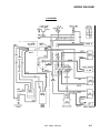
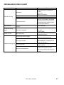
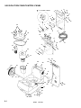
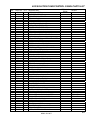
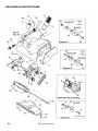
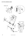
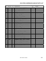
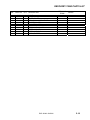
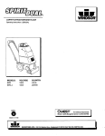
1
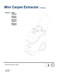
CARPET EXTRACTOR
MODEL
EXP
POWER SOURCE
115V ELECTRIC
Read these instructions before using the machine
AB
98363 08/14/07
MACHINE DATA LOG/OVERVIEW
MODEL _______________________________________
DATE OF PURCHASE __________________________
SERIAL NUMBER ______________________________
SALES REPRESENTATIVE # _____________________
DEALER NAME ________________________________
OPERATIONS GUIDE NUMBER ___________________
PUBLISHED __________________________________________
YOUR DEALER
Name: __________________________________________________________________________________________________
Address: _______________________________________________________________________________________________
For the name and address of your dealer contact: Windsor Industries
Phone Number: _________________________________________________________________________________________
1
EXP 98363 08/25/04
TABLE OF CONTENTS
Machine Data Log/Overview.........................1
Table of Contents..........................................2
HOW TO USE THIS MANUAL
How to use this Manual.................................1-1
SAFETY
Important Safety Instructions ........................2-1
Hazard Intensity Level ..................................2-2
Grounding Instructions..................................2-3
OPERATIONS
How It Operates. ...........................................3-1
Controls.........................................................3-2
Operating Instructions...................................3-3
MAINTENANCE
Protect From Freezing. .................................4-1
Daily/ Regular Maintenance..........................4-1
Periodic Maintenance. ..................................4-1
Brush Assembly ............................................4-1
Service Schedule ..........................................4-2
To Access Pump & Brush Motor ..................4-3
Solution Valve Cable Adjustment .................4-3
Spray Jet ......................................................4-3
Vac Motor Brushes ......................................4-4
Vacuum Motor Replacement. .......................4-4
Wiring Diagram. ............................................4-5
Troubleshooting Chart ..................................4-6
GROUP PARTS LIST
Vac/Solution Tank/Control Panel. ............... 5-1
Brush/Brush Motor/Frame........................... 5-3
Pump Assembly. ......................................... 5-5
Solution Lever/Main Handle........................ 5-7
Recovery Tank............................................ 5-9
Solution Plumbing/Spray Jet....................... 5-11
Suggested Spare Parts/Accessories .......... 5-13
Warranty ...........................................…...…5-14
EXP 98363 08/25/04
2
HOW TO USE THIS MANUAL
The SAFETY section contains important information
regarding hazard or unsafe practices of the
machine. Levels of hazards is identified that could
result in product or personal injury, or severe injury
resulting in death.
This manual contains the following sections:
-
-
HOW TO USE THIS MANUAL
SAFETY
OPERATIONS
MAINTENANCE
PARTS LIST
The HOW TO USE THIS MANUAL section will tell
you how to find important information for ordering
correct repair parts.
Parts may be ordered from authorized dealers.
When placing an order for parts, the machine model
and machine serial number are important. Refer to
the MACHINE DATA box which is filled out during
the installation of your machine. The MACHINE
DATA box is located on the inside of the front cover
of this manual.
MODEL _____________________________________
The OPERATIONS section is to familiarize the
operator with the operation and function of the
machine.
The MAINTENANCE section contains preventive
maintenance to keep the machine and its
components in good working condition. They are
listed in this general order:
-
Periodic
Daily/Regular
Troubleshooting
The PARTS LIST section contains assembled parts
illustrations and corresponding parts list. The parts
lists include a number of columns of information:
DATE OF PURCHASE ________________________
-
SERIAL NUMBER ____________________________
SALES REPRESENTATIVE # ___________________
-
DEALER NAME ______________________________
OPERATIONS GUIDE NUMBER __________________
-
PUBLISHED ________________________________
-
The model and serial number of your machine is
located on the lower left back panel.
-
REF – column refers to the reference
number on the parts illustration.
PART NO. – column lists the part
number for the part.
QTY – column lists the quantity of the
part used in that area of the machine.
DESCRIPTION – column is a brief
description of the part.
SERIAL NO. FROM – column indicates
the first machine the part number is
applicable to. When the machine design
has changed, this column will indicate
serial number of applicable machine.
The main illustration shows the most
current design of the machine. The
boxed illustrations show older designs.
If column has an asterisk (*), call
manufacturer for serial number.
NOTES – column for information not
noted by the other columns.
NOTE: If a service or option kit is installed on your
machine, be sure to keep the KIT INSTRUCTIONS
which came with the kit. It contains replacement
parts numbers needed for ordering future parts.
NOTE: The 98# on the lower left corner of the front
cover is the part number for this manual.
1-1
EXP 98363 08/25/04
IMPORTANT SAFETY INSTRUCTIONS
When using an electrical appliance, basic precaution
must always be followed, including the following:
READ ALL INSTRUCTIONS BEFORE USING THIS MACHINE.
This machine is for commercial use.
! WARNING:
To reduce the risk of fire, electric shock, or injury:
Connect to a properly grounded outlet. See Grounding Instructions.
Do not leave the machine unattended. Unplug machine from outlet when not in use and before maintenance or
service.
Use only indoors. Do not use outdoors or expose to rain.
Do not allow machine to be used as a toy. Close attention is necessary when used by or near children.
Use only as described in this manual. Use only manufacturer’s recommended components and attachments.
Do not use damaged electrical cord or plug. Follow all instructions in this manual concerning grounding the
machine. If the machine is not working properly, has been dropped, damaged, left outdoors, or dropped into
water, return it to an authorized service center.
Do not pull or carry machine by electrical cord, use as a handle, close a door on cord, or pull cord around sharp
edges or corners.
Do not run machine over cord. Keep cord away from heated surfaces.
Do not unplug machine by pulling on cord. To unplug, grasp the electrical plug, not the electrical cord.
Do not handle the electrical plug or machine with wet hands.
Do not operate the machine with any openings blocked. Keep openings free of debris that may reduce airflow.
This machine is intended for cleaning carpet only.
Do not vacuum anything that is burning or smoking, such as cigarettes, matches, or hot ashes.
This machine is not suitable for picking up health endangering dust.
Turn off all controls before unplugging.
Machine can cause a fire when operating near flammable vapors or materials. Do not operate this machine near
flammable fluids, dust or vapors.
This machine is suitable for commercial use, for example in hotels, schools, hospitals, factories, shops
and offices for more than normal housekeeping purposes.
Maintenance and repairs must be done by qualified personnel.
If foam or liquid comes out of machine, switch off immediately.
SAVE THESE INSTRUCTIONS
EXP 98363 08/25/04
2-1
HAZARD INTENSITY LEVEL
The following symbols are used throughout this guide as indicated in their descriptions:
HAZARD INTENSITY LEVEL
There are three levels of hazard intensity identified by signal words -WARNING and CAUTION and FOR
SAFETY. The level of hazard intensity is determined by the following definitions:
! WARNING
WARNING - Hazards or unsafe practices which COULD result in severe personal injury or death.
! CAUTION
CAUTION - Hazards or unsafe practices which could result in minor personal injury or product or property
damage.
FOR SAFETY: To Identify actions which must be followed for safe operation of equipment.
Report machine damage or faulty operation immediately. Do not use the machine if it is not in proper
operating condition. Following is information that signals some potentially dangerous conditions to the
operator or the equipment. Read this information carefully. Know when these conditions can exist. Locate
all safety devices on the machine. Please take the necessary steps to train the machine operating
personnel.
FOR SAFETY:
DO NOT OPERATE MACHINE:
Unless Trained and Authorized.
Unless Operation Guide is Read and understood.
In Flammable or Explosive areas.
In areas with possible falling objects.
WHEN SERVICING MACHINE:
Avoid moving parts. Do not wear loose clothing; jackets, shirts, or sleeves when working on the
machine. Use Windsor approved replacement parts.
.
2-2
EXP 98363 08/25/04
GROUNDING INSTRUCTIONS
THIS PRODUCT IS FOR COMMERCIAL USE ONLY.
ELECTRICAL:
In the USA this machine operates on a standard 15 amp
115V, 60 hz, A.C. power circuit . The amp, hertz, and
voltage are listed on the data label found on each
machine.
Using voltages above or below those
indicated on the data label will cause serious damage to
the motors.
GROUNDING INSTRUCTIONS:
This appliance must be grounded.
If it should
malfunction or break down, grounding provides a path of
least resistance for electric current to reduce the risk of
electric shock. This appliance is equipped with a cord
having an equipment-grounding conductor and
grounding plug. The plug must be inserted into an
appropriate outlet that is properly installed and grounded
in accordance with all local codes and ordinances.
This appliance is for use on a nominal 115-volt circuit,
and has a grounded plug that
looks like the plug in “Fig. A”. A temporary adaptor that
looks like the adaptor in “Fig . C” may be used to
connect this plug to a 2-pole receptacle as shown in
“Fig. B”, if a properly grounded outlet is not available.
The temporary adaptor should be used only until a
properly grounded outlet (Fig. A) can be installed by a
qualified electrician. The green colored rigid ear, lug, or
the like extending from the adaptor must be connected
to a permanent ground such as a properly grounded
outlet box cover. Whenever the adaptor is used, it must
be held in place by a metal screw.
PROPER GROUNDING
Grounding Pin
Grounded
Outlet
Metal Screw
Adaptor
Grounded Outlet Box
Fig. A
Fig. B
Tab For Grounding Screw
Adaptor
Fig. C
NOTE: In Canada, the use of a temporary adaptor is not
permitted by the Canadian Electrical Code
! WARNING:
Improper connection of the equipment-grounding
conductor can result in a risk of electric shock. Check
with a qualified electrician or service person if you are in
doubt as to whether the outlet is properly grounded. Do
not modify the plug provided with the appliance - if it will
not fit the outlet, have a proper outlet installed by a
qualified electrician.
EXP 98363 08/25/04
2-3
OPERATIONS
HOW IT OPERATES:
CHEMICALS
This machine is a portable, easy to use carpet extractor
designed for use indoors, in a household or light
industrial environment.
When operating as a carpet extractor, cleaning solution
is dispensed onto the carpet and agitated by a rotating
brush. The solution is then extracted from the carpet by
a vacuum. The head on the brush is floating, allowing it
to automatically adjust to various carpet depths while
applying an effective brush pressure.
Use only the suitable chemicals listed below.
Using incompatible chemicals will damage the
machine. Damages of this type are not covered
under warranty. Carefully read ingredients on
manufacturer’s label before using any product in
this machine.
1. To avoid electric shock use indoors only.
2. To reduce risk of fire, do not use volatile
substances.
3. Use only cleaners intended for carpet
application.
Suitable
Chemicals
Alkalis
Defoaming Agents
Detergents
Soaps
Vinegar
Hydroxides
INSPECTION:
Carefully unpack and inspect your extractor for shipping
damage.
Each unit is operated and thoroughly
inspected before shipping, and any damage is the
responsibility of the carrier, who should be notified
immediately.
ELECTRICAL:
This extractor operates on a standard 15 amp 120 volt
AC circuit. This is the typical wall receptacle found in
household and light industrial environments. Voltages
below 105 volts or above 125 volts could cause serious
damage to motors. *Special voltage models available. A
wiring diagram is mounted inside the rear control panel
of machine. A copy of the wiring diagram is included in
this Owner’s Guide.
EXTENSION CORDS:
If an extension cord is used, the wire size must be at
least one size larger than the power cord on the
machine: This extractor is equipped with a 25 ft. 16/3
power cord.
To avoid possible distortion of polyethylene
solution/recovery tanks, DO NOT USE WATER
TEMPERATURE THAT EXCEEDS 140 F (60 C).
3-1
EXP 98363 08/25/04
Incompatible
Chemicals
Aldehydes; Butyls
Carbon Tetrachloride
Chlorinated Bleaches
Chlorinated Hydrocarbons
Trichlorethylene
Phenols; Methyls (MEK)
Perchlorethylene (perc)
Aromatic Hydrocarbons
D-Limonene
CONTROLS
1
Brush Switch On/Off. Turns brush motor on and off.
2
Solution Switch On/Off. Turns solution pump on and off.
3
Vac Switch On/Off . Turns vacuum motor on and off.
4
Main Handle.
5
Solution Lever. Controls the amount of
flow of solution to the floor.
VIEW: TOP of CONTROL
6
Brush Motor Circuit Breaker.
Protects brush motor from overheating.
7
Vac Motor Circuit Breaker. Protects the
vac motor from overheating.
8
Handle Adjustment Lever.
Adjusts the main handles angle.
9.
Solution Tank Drain Hose.
2
1
3
VIEW: REAR of MACHINE
4
5
12
10. Accessory Tool Connection. Solution connection for
accessory tools.
11.
Accessory Hose Connection. Hose
connection for accessory tool.
8
12. Cord Hook.
6
VIEW: FRONT of MACHINE
7
Dome
Recovery
Tank
9
Solution
Tank
NOTE:
Attach
strain
relief/cord RETAINER TO
ATTACH
STRAIN
RELIEF/CORD
retainer
to theCORD.
power cord.
THE POWER
10
1. Make a loop in power cord approximately
12” from strain relief on machine.
11
Vacuum
Shoe / Brush
Housing
2. Slide cord loop through slot
in retainer arm. Pull slack
cord back through slot to
secure. Attach retainer to
handle.
EXP 98363 08/25/04
3-2
OPERATIONS
OPERATING INSTRUCTIONS
A. FILLING THE SOLUTION TANK:
1. Remove clear dome from recovery tank.
2. Lift upper recovery tank from machine and
set aside.
3. Use a clean bucket or hose to fill solution
tank with hot water. The solution tank holds
4 gallons (15.2 liters) of cleaning solution.
Do not use the recovery tank to fill the solution
tank. Sediment in the recovery tank can damage
the solution pump and clog the spray jets,
rendering the machine inoperable.
4. Add a non-foaming concentrate for use in
hot water extractors at the proportions noted
on the container.
Note: Periodically operate the extractor with only hot
water to remove chemical residue in carpet.
To avoid possible distortion of the polyethylene
solution/recovery tanks, DO NOT USE WATER
WITH A TEMPERATURE THAT EXCEEDS 140°F
(60°C).
5. Place recovery tank back on machine.
6. Place dome on recovery tank. Make sure
dome is seated correctly to ensure proper
vacuum seal.
NOTE: If solution does not dispense in an even
pattern across the width of the machine, the spray
jet may be clogged. Tilt the machine back and
remove the spray tip by pushing in and turning it
one quarter turn. Wash it thoroughly, and blow dry.
NOTE: Do not use pins, wire, etc. to clean spray jet
nozzle as this will deform the jet and destroy the
spray pattern.
6. Begin with the machine at the edge of the
carpet. Actuate the solution lever while pulling
the machine backwards. Release solution lever
at least 12 inches before the end of each
cleaning pass. This will ensure all dispensed
cleaning solution is extracted from carpet.
While operating machine, check for excessive
foam buildup in the recovery tank. If excessive
foam is present, add a defoamer solution to
recovery tank, or empty tank.
7. Empty recovery tank when approximately 3/4
full. If the recovery tank is overfilled, the water
will drain back onto the carpet when the vacuum
is switched off.
8. Ventilate area after carpet has been cleaned.
Keep children and pets away and do not walk
on carpet until it is dry.
A Windblower™ fan can be used to reduce drying time.
Use only the suitable chemicals listed in the
Chemical Section. Using incompatible
chemicals will damage the machine. Carefully
read ingredients on manufacturer’s label before
using any product in this machine.
OPERATING MACHINE WITH
ACCESSORY TOOLS
OPERATING THE MACHINE
1.
1. Vacuum the carpet and make sure it is cleared
of surface debris before cleaning.
2. Plug power cord into a grounded wall outlet.
2.
This extractor is easily adapted for use with Windsor
accessory tools: Contact Customer Service for details.
3.
Defeating the grounding pin on the power cord
can result in a severe electrical shock.
3. Turn on the pump, brush and vacuum switches,
listening for each motor to turn on.
NOTE: The vacuum and the brush are protected by
circuit breakers located on the back panel, below
their respective switch.
Lift flap on the front of the vac shoe and insert
hose cuff into the vac shoe, ensuring that there is
a tight fit.
Attach the solution hose from accessory tool to the
brass solution fitting on the front of machine.
Switch on the pump and the vacuum. The
application of cleaning solution is now controlled
by the lever on the accessory tool.
Do not switch on brush when operating the
machine with accessory tools. Carpet damage
may occur.
NOTE: The solution pump is not intended to run dry.
When using the extractor for vacuum pick-up only,
insure that the pump switch is turned off.
NOTE: If either of these motors does not respond to
being switched on, reset the circuit breakers by
pressing them in, and attempt to switch the machine
on again.
3-3
EXP 98363 08/25/04
MAINTENANCE
PROTECT FROM FREEZING
If it becomes necessary to store in temperatures that
could drop below 40°F, the pumping system, hoses
and valves must be protected from freezing with a
methyl hydrate window washer antifreeze solution.
NOTE: Do not use ethylene glycol or cooling system
antifreezes.
1. Add one gallon of window washer antifreeze to
the supply tank.
2. Turn on pump switch and spray until the
antifreeze solution fills the solution lines.
3. Drain the leftover antifreeze from the supply tank.
Always allow the unit to reach room temperature
before filling with hot water or operating.
4. Before operation be sure to flush system
completely. Failure to do so after winterizing
machine will damage carpet.
3. Periodically inspect all hoses, electrical cables, filters,
gaskets and connections on your machine. Frayed
or cracked hoses should be repaired or replaced to
eliminate vacuum or solution pressure loss.
4. The electrical cable must be well insulated, if the
cable insulation is broken or frayed, repair or
replace it immediately. Don't take chances with
electrical fire or shock.
5. The filter in the bottom of the solution tank must
be clean to allow free flow of cleaning solution.
The screen filter on the vacuum tube in the
recovery tank must be free of lint buildup to
ensure full vacuum strength.
6. The dome gasket must be properly seated and
free of damage to create the air seal needed to
extract water.
MAINTENANCE INSTRUCTIONS
! WARNING
Remove machine power cord from electrical
source before making any adjustments or repairs
to the machine.
DAILY/REGULAR MAINTENANCE
! WARNING
Before making any adjustments or repairs to the
machine, disconnect the power cord from the
electrical source.
1. Empty unused cleaning solution from the
solution tank.
2. Inspect and clean filter screens in solution tank,
and on top of tube in recovery tank.
3. Flush pumping system with 1 or 2 gallons of
clean, hot water.
4. Check spray jet for full spray pattern.
5. Empty the recovery tank and rinse with clean water.
6. Check for and remove any lint or debris around
brush and vac shoe.
PERIODIC MAINTENANCE
1. After every 25 hours of operation, flush a white
vinegar solution (ONE quart vinegar to two
gallons of water) or anti-browning solution (mixed
as directed) through the extractor. This will
prevent build-up of alkaline residue in the system.
! WARNING
Only qualified maintenance personnel are to
perform repairs.
BRUSH ASSEMBLY
1. Situate machine in order to access bottom cover.
Remove screws (6) and bottom cover. Remove
screws (3) and belt cover.
2. Loosen nuts at brush motor and slide motor
forward to reduce belt tension. Remove belt.
3. Remove lower brush stop on belt side (closest to
you with machine upside down) and rotate black
plastic finger guard toward rear of machine.
4. Remove one screw holding each brush bearing
to brush bracket.
5. With the blade of a screw driver, bend bearings
inward enough to disengage locating tabs.
6. Slide brush, axle, and bearing out of brush bracket.
2. If the spray jet becomes clogged, remove the
spray tip, wash it thoroughly, and blow dry.
7. Inspect/replace brush and bearings as required.
The brush is equipped with yellow wear indicator
Bristles. The brush should be replaced when it
wears down to the height of the yellow bristles.
NOTE: Do not use pins, wire, etc. to clean spray jet
nozzle as this will deform the jet and destroy the spray
pattern.
8. When reinstalling brush, check belt for proper tension.
EXP 98363 08/25/04
4-1
MAINTENANCE
SERVICE SCHEDULE
MAINTENANCE
Check machine for cord damage
Check recovery dome and gasket for
damage and cleanliness
Check brush – should be clean with no
lint or strings attached
Inspect vac shoe for blockage; remove
fibers with coat hanger, etc.
Check hoses for wear, blockages, or
damage
Check handles, switches, and knobs
for damage
Check vac motor intake filter and clean
Run one gallon of water through
system
Clean out recovery tank and check
float valve to make sure it moves freely
Clean out solution tank and remove
and clean vacuum intake screen
Clean outside of all tanks and check for
damage
Run vac motor for at least one minute
to allow motor to dry
Store with dome off tank to allow the
tank to dry
Check all bearings for noise
Check all gaskets for wear and leakage
Check vacuum intake screen for
damage; replace if necessary
Check pump pressure; observe spray
pattern and check with gauge if
necessary
Check and clean solution screen
Check belts for wear and replace as
necessary
Check brush for wear; ensure bristles
are not damaged
Check cables for fraying
Check the spray bar (manifold) for
damage; replace if broken or bent
Check condition of vac shoe and frame
for damage
Check overall performance of machine
Check vac motor carbon brushes
4-2
DAILY
WEEKLY
QUARTERLY
*
*
*
*
*
*
*
*
*
*
*
*
*
EXP 98363 08/25/04
*
*
*
*
*
*
*
*
*
*
*
*
MAINTENANCE
TO ACCESS PUMP AND BRUSH MOTOR
1. Situate machine in order to access bottom
cover. Remove screws (6) and bottom cover.
2. To remove brush motor, loosen nuts at brush
motor and slide motor forward to reduce belt
tension. Remove belt. Continue loosening nuts
at brush motor until free from brush bracket.
Disconnect wires.
3. To remove pump, loosen screws holding pump
mounting bracket to casting and remove as one
unit. Lift pump and mounting bracket up to
gain access to all hose clamps which need to
be removed before pump is free from machine.
Disconnect wires.
SPRAY JET
Note: To prevent a clogged jet due to alkali build-up,
the spray system should be flushed with 1 to 2
gallons of clean hot water at the end of each day.
1.
Situate machine in order to access bottom
cover.
2.
The machine is equipped with a ”Quick
Change” jet that can be easily removed for
cleaning. To remove- push jet in and rotate
1/4 turn.
3.
Wash jet and blow dry. Do not use pins or
wire to remove obstruction as this will change
spray pattern.
SOLUTION VALVE CABLE ADJUSTMENT
The solution valve cable has been factory set so that
action of the solution lever moves the valve from
fully closed to fully open. As the machine operates
the cable will stretch and the lever will not be able to
fully open the valve. The play in the solution lever
should be checked periodically and adjusted when
needed as described below.
1.
Loosen the lock nut at the point where the
cable enters the lever housing on the
machine handle.
2.
Turn the threaded end of the cable sleeve
to adjust. Threading the end further into the
housing will slacken the cable, increasing
the play in the lever. Threading the end out
of the housing will tighten the cable,
decreasing the play in the lever.
3.
Tighten the locking nut against the housing
after adjusting the play as required.
4.
If there is not enough thread adjustment
available, the cable length can be adjusted
directly at its connection to the solution
valve. This is accessed by removing the
back control panel.
EXP 98363 08-25-04
4-3
MAINTENANCE
Vacuum Motor Carbon Brushes Replacement (Ametek)
ONLY QUALIFIED MAINTENANCE PERSONNEL
ARE TO PERFORM THE FOLLOWING REPAIRS.
VACUUM MOTOR REPLACEMENT
1. Turn off all switches and unplug machine.
2. Remove recovery tank.
3. Remove the 5 screws holding the vacuum motor
cover to the solution tank.
4. Locate the vacuum motor wires and disconnect
at the connector.
5. Remove the vacuum motor.
6. Reverse process to install.
End Cap
Carbon
Brushes
WARNING: The green
ground wire must be
attached for safe operation.
See wiring diagram.
Note: When replacing carbon brushes loosen wire terminal
BEFORE removing screws on bracket.
Make sure the excess wire lengths do not get
pinched in the gaskets which seal the vac motor.
If need be, remove the rear control panel and pull
excess lead length out of the vac motor
compartment.
Wire
Terminal
The vac motor is protected by a circuit breaker
located in the switch panel. The breaker will only
trip under conditions of abuse.
Note:
Place
stop in
groove.
Vacuum Motor Carbon Brushes Replacement (Windsor)
End Cap
Carbon
Brushes
WARNING: The green
ground wire must be
attached for safe operation.
See wiring diagram.
If armature commutator is grooved, extremely pitted or not
concentric, the motor will need to be replaced or sent to a
qualified service center.
Important:
These brushes wear quicker as the length shortens due to
increased heat. Spring inside brush housing will damage
motor if brushes are allowed to wear away completely.
If armature commutator is grooved, extremely pitted or not
concentric, the motor will need to be replaced or sent to a
qualified service center.
Wire Terminal
Important:
These brushes wear quicker as the length shortens due to
increased heat. Spring inside brush housing will damage
motor if brushes are allowed to wear away completely.
3/8 (9.5mm)
Periodically check the length of the carbon brushes. Replace
both carbon brushes when either is less than 3/8" (9.5mm)
long.
3 [9.5mm]
8
Periodically check the length of the carbon brushes. Replace
both carbon brushes when either is less than 3/8" (9.5mm)
long.
4-4
EXP 980363 08/25/04
WIRING DIAGRAM
115V EXPERT
ORG
BLK
15
EXP 98363 08/25/04
4-5
TROUBLESHOOTING CHART
PROBLEM
No Power, Nothing
Runs
Vacuum Motor Will Not
Run
Vacuum Motor Runs
But Suction Is Poor
Poor Or No Water Flow
(Carpet Is Streaky)
Brush Does Not Spin
Accessory Tool Fitting
Difficult to Connect
4-6
CAUSE
Is the cord plugged in.
Circuit breaker tripped in building.
Faulty switch.
Faulty power cord or pigtail.
Vacuum circuit breaker tripped.
Faulty main vacuum switch.
Loose wiring.
Faulty vac motor.
Debris lodged in vac shoe.
Dome gasket defective or missing.
Vacuum hose cracked or hose cuff loose.
Recovery tank full / float ball stuck in the
up position.
Main pump switch off.
Jets clogged or missing.
Solution filter clogged.
Faulty solenoid.
Brush switch off.
Brush circuit breaker tripped.
Brush belt broken.
Faulty brush motor.
Corrosion on fitting.
EXP 98363 08/25/04
SOLUTION
Plug in cord.
Reset breaker
Call for service.
Call for service.
Reset breaker
Call for service.
Call for service.
Call for service.
Remove debris from vac shoe.
Replace as necessary.
Replace or repair as necessary.
Turn off vac motor. Drain and rinse
recovery tank.
Turn on.
Clean using a vinegar /water solution or
replace.
Drain solution tank and clean solution
filter.
Call for service.
Turn on brush switch.
Reset circuit breaker.
Replace as necessary.
Call for service.
Clean with steel wool.
Remove and soak in acetic acid (white
vinegar).
Lubricate lightly with silicone base
lubricant.
TROUBLESHOOTING CHART
PROBLEM
CAUSE
Belt broken.
Brush Not Turning
Faulty switch.
Faulty circuit breaker.
Faulty brush motor.
Worn Bearings
Squealing or grinding sound in brush
housing.
Carpet Not Getting
Clean
Severe soil conditions
Carpet Too Wet
Worn spray jet(s)
Solution filter screen clogged.
Spray jet(s) clogged.
Carpet Not Getting Wet
Pump not running.
Solution valve adjustment.
EXP 98363 08/25/04
SOLUTION
Remove belt cover on right side of
machine.
Inspect belt.
Replace if necessary.
Replace.
Replace
If the belt, circuit breaker, and switch
have been tested and found to be in
good working order, the brush motor
may need to be replaced.
Replace bearings.
Make several passes at right angles to
each other.
Use a pre-spray.
Replace spray jets which are producing
more than a fine mist.
Clean solution filter screen located
inside lower tank near the front.
Clean or replace jets. Do not use a
wire to clean jet. Damaged jets will
cause over-saturation.
Check for and correct any loose wires.
Repair or replace.
Adjust solution valve cable until valve
operates when handle is pulled.
Align slit in jet parallel with center line
of brush.
4-7
VAC/SOLUTION TANK/CONTROL PANEL
*
8
“-“ IN LOWER CORNER
2
*
7
1
13
4
3
1
5
26
49
25
14
16
52
17
48
18
15
21
47
22
45
46
20
23
19
1
19
40
51
44
24
25
39
43
38
37
42
36
41
34
33
32
31
29
30
28
5-1
10
11
6
50
9
98363 12/04/04
35
27
25
26
12
VAC/SOLUTION TANK/CONTROL PANEL PARTS LIST
REF
PART NO.
QTY
1
2
3
4
5
6
7
8
9
10
11
12
13
14
15
16
17
18
19
20
21
22
23
24
25
26
27
28
29
30
31
32
33
34
35
36
37
38
39
40
41
42
43
44
45
45A
45B
46
47
48
49
50
51
52
57104
67029
14622
14020
57116
14700
87100
500225
14942
70595
70211
70235
500226
23664
73710
72069
27417
70547
70532
57208
27376
880041
20086
70222
87189
70745
27787
35182
70393
70627
20035
62717
34331
73864
35222
50746
70517
51254
50776
35193
03102
87146
89507
57196
53771
41258
140687
39276
27759
35169
27631
35175
27632
500551
4
1
1
1
2
1
1
1
2
1
1
2
1
1
1
3
1
1
3
1
3
1
1
2
13
11
1
4
4
4
1
2
1
1
1
1
4
2
1
1
1
2
2
2
1
1
1
1
1
2
1
1
SERIAL NO.
FROM
DESCRIPTION
NUT, #10-32 KEPS
RECTIFIER, BRIDGE
BREAKER, 1.5A CIRCUIT
TERMINAL BLOCK
NUT, #6-32 KEPS
BREAKER, 15A 250 VAC 50 VDC
WASHER, 3/8 INT. LOCK THIN
LABEL, CIRCUIT BREAKER VAC
COVER, CIRCUIT BREAKER
SCREW, 10-32 X 1 PHMS GRN
SCR, 10-32 X 3/4 PH. BLK NYLON
SCREW, 6-32 X 1.0 PH BLK NYLON
LABEL, CIRCUIT BREAKER BRUSH
CORD ASM, 115V
STRAIN RELIEF, PG11 METRIC TRUMPET
SWITCH, 125V DPDT
CORD, 1/8” X 12”
SCREW, #10-32 X 1 PPHMS BLK
SCREW, 10-32 X 1/2 PHMS BLK
NUT PG11 METAL, 1.024 OD X 0.73 ID
CLIP, SWITCH RETAINING
WIRE ASM, PANEL TO BASE
CLAMP, CORD
SCR, #8 X ½ PPHST BLK
WASHER, .2 ID X .5 OD BLK SS
SCR, #10-5/8 PPHST HI LO BLK
COVER, REAR (CONTROL PANEL)
GASKET, FRAME
SET SCR, 1/4-20 X 1.25L
SCR, 1/4 X 1/2 PPHST HI-LO
CLAMP, 7/16 DIA. NYLON UL
PLATE, AXLE EXP
FRAME/SOL EXP II
STRAINER, 3/8” NPT 60 MESH
GASKET, 2 ID X 2.75 X 3/8 THK PORON
LABEL, WIRING DIAGRAM
SCREW, 8-32 X 1/2 FHMS SS
LOCK, HANDLE EXPERT TANK
LABEL, FOR SAFETY
GASKET, REAR COVER
AXLE, WHEEL
WASHER, 1/2 ID X 1” OD X .08” NYLON
WHEEL, 8” GREY (HOOSIER)
HUBCAP, 1/2” DIA
VAC MOTOR ASM, 115V EXP.
BRUSH SET, 120V 5.7 VAC, AMETEK
BRUSH SET, 120V VAC, WINDSOR
HOSE, 1.5” X 14” VAC
CUFF, 1.5” BLACK HOSE
GASKET, VAC COVER
COVER, VAC MOTOR
GASKET, TANK TO VAC COVER
CAP, VAC MOTOR
LABEL, CONTROL PANEL MAIN
98363 08/14/07
NOTES:
10000443236
1000001018
1000028686
1000121568
SERVICE ONLY
SERVICE ONLY
5-2
BRUSH/BRUSH MOTOR/FRAME
5-3
EXP 98363 08/25/04
BRUSH/BRUSH MOTOR/FRAME PARTS LIST
SERIAL NO.
FROM
REF
PART NO.
QTY
DESCRIPTION
1
2
3
4
5
6
7
8
9
10
11
12
13
14
15
16
17
18
19
20
21
22
23
24
25
26
27
28
29
30
31
32
33
34
35
36
37
38
39
40
41
42
43
44
41279
27674
39276
35195
27759
67138
57104
57030
70557
70532
27636
20016
87139
09113
70740
64085
53608
140036
09114
140040
64086
11039
03084
35176
39468
27639
35171
140087
56012
70303
09117
57018
70578
70031
87003
62556
70595
20086
73781
70351
70604
87189
1
1
REF
1
1
1
2
6
4
5
1
1
4
1
3
1
1
1
1
1
1
1
1
1
REF
1
1
1
1
2
2
2
2
2
1
1
1
1
4
4
1
1
HOUSING, BRUSH W/VAC SHOE
COVER, ACCESS PORT
HOSE, 1.5 BLK VAC X 14”
GASKET, .25 X .75 X 2.00 L
CUFF, 1.5” BLACK HOSE
RING, 3/8 EXTERNAL SNAP
NUT, 10-32 W/STAR WASHER SHOE
NUT, 10-32 NYLOCK
SCR, 10-32 X 1” FHMS BLK
SCR, 10-32 X 1/2 PPHMS BLACK
COVER, BELT
CLAMP, 1/4 ID HOSE
WASHER, 3/16 FLAT
BEARING, RIGHT
SCR, 10-32 X 1/2 PTHMS BLK
PULLEY, MOTOR
MOTOR ASM, BRUSH DRIVE
BRACKET ASM, BRUSH MOTOR
BEARING, LEFT
BRUSH
PULLEY, BRUSH
BELT, BRUSH DRIVE
AXLE, BRUSH
GASKET, BOTTOM COVER
HOSE, ¼ ID NYLOBRD X 11.5”
COVER, BOTTOM
GASKET, ACCESS PORT COVER
BULKHEAD, 1/4 MPT X 1/4 BARB
NIPPLE, 1/4 FPT QD
SHOULDER BOLT, 1/4 OD X 5/8 L
OPEN
BEARING, BRUSH BRACKET
NUT, 10-24 HEX LOCK
SCREW, 8-32 X 1” FHMS SS
SCR, 10-32 X 1/4 PPHMS
WASHER, 3/8 ID X 7/8 OD SS
PLATE, GUARD ON LEFT SIDE ONLY
OPEN
SCR, 10-32 X 1.0 PHMS GRN
CLAMP, CORD
HOSE, 5/16 X 3/16 ID CLR VINYL
SCR, 10-32 X 3/8 HHTR W/STAR
SCR, 10-32 X 5/8 PHMS BLK
WASHER, .2 ID X .5 OD BLK SS
NOTES:
NOTE: The left and right sides of the machine are assigned as if
standing behind the machine in the operator’s position.
EXP 98363 08/25/04
5-4
PUMP ASSEMBLY
5-5
EXP 98363 08/25/04
PUMP ASSEMBLY PARTS LIST
REF
PART NO.
QTY
1
2
3
4
5
6
7
8
9
10
11
12
13
14
20016
39510
39468
39508
70484
87016
140034
40009
40065
65164
70581
78024
40033
20042
2
1
1
1
2
2
1
1
1
1
2
1
1
1
SERIAL NO.
FROM
DESCRIPTION
NOTES:
CLAMP, 1/4 ID HOSE
HOSE, 3/8 WIREBOUND X 3”
HOSE, 1/4 NYLOBRAID X 11.5”
HOSE, 1/4 NYLOBRAID X 15”
SCR, 10-32 X 5/8 PPHMS SS
WASHER, #10 LOCK EXT. STAR
BRACKET, PUMP
HOSEBARB, 1/4 MPT X 1/4
HOSEBARB, 1/4 MPT X 1/4 X 90°
PUMP ASM, EXPERT
SCR, 10-32 X 3/8 HHTFW/WASH
TEE, 1/4 BRANCH
HOSEBARB, 1/4 MPT X 3/8 90°
CLAMP, 3/8 (D-SLOT)
EXP 98363 08/25/04
5-6
SOLUTION LEVER/MAIN HANDLE
5-7
EXP 98363 08/25/04
SOLUTION LEVER/MAIN HANDLE PARTS LIST
REF
PART NO.
QTY
1
2
3
4
5
6
7
8
9
10
11
12
13
14
15
16
17
18
19
20
21
22
23
24
25
26
27
28
29
30
31
32
33
34
35
36
37
38
39
40
41
42
43
57238
51251
41302
70537
36046
38247
27785
87029
57234
57022
87080
87016
87139
67397
80604
51142
66133
51184
62716
73735
70556
84153
40065
57018
89144
41144
70361
50729
27417
73169
99620
70031
40043
39508
39507
88551
20016
73866
140308
70745
66086
3
1
2
3
1
1
1
1
1
1
1
3
2
1
1
1
1
2
1
1
1
1
2
1
1
1
2
1
1
1
7”
4
1
1
1
1
2
1
1
3
1
DESCRIPTION
NUT, 10-24 JOINT CONNECTOR BLK
LEVER, SOLUTION
HOUSING, SOLUTION LEVER
SCR, 10-24 TRUSS HEAD BLK
GRIP, HANDLE X 13”
HANDLE
CABLE, VALVE SOLUTION 27-1/2 LG
WASHER, 5/16 FLAT SAE
NUT, 3/8-16 SQUARE
NUT, 3/8-16 HEX NYLOCK
WASHER, .52 1.25 FLAT PLTD
WASHER, #10 LOCK
WASHER, 3/16 FLAT USS
ROD, HANDLE ADJUSTMENT EXP II
RING, RUE COTTER 1/4”
LEVER, HANDLE LOCK
PIN, CLEVIS
LOCK, HANDLE ADJUSTMENT
PLATE, STOP EXPT
SPACER, 1.0 OD X .26 ID X 1 BLK NYL
SCREW, 1/4-20 X 1.5 SS
VALVE, KINGSTEN
HOSEBARB, 1/4 MPT X 1/4 90°
OPEN
OPEN
NUT, 10-24 LOCK
WELDMENT, LEVER VALVE EXP
HOOK, CORD
SCR, #10-32 X 1/2 PHTR
CARD, INSTRUCTION
CORD, 1/8 X 12”
STRAIN RELIEF, CORD HOOK
HEAT SHRINK, 3/8 ID UL/CSA
SCR, 10-32 X 1/4 PPHMS PLTD
HOSEBARB, 3/8 MPT X 3/8 90° NYLON BLK
HOSE, 1/4 NYLOBRAID 15”
HOSE, 1/4 NYLOBRAID 17”
WIRE ASM, 19” GRN/18 78008 X 78008
CLAMP, 1/4 ID HOSE
SPACER, 1/2 OD X .219 ID X 1/2 NYLON
BRACKET, VALVE EXPERT
SCR, #10-5/8 PPHST HI LO BLK
PIN, ROLL 3/16 X 5/8
EXP 98363 02/23/05
SERIAL
NO.
NOTES:
441847
WAS 57138 (QTY 1)
441847
(QTY WAS 3)
5-8
RECOVERY TANK
9
TO REAR
COVER
1
7
10
4(3)
8
3
5
2
6
11
5-9
EXP 98363 08/25/04
RECOVERY TANK PARTS LIST
REF
PART NO.
QTY
1
2
3
4
5
6
7
8
9
10
11
28050
35178
62465
70114
35167
75212
34140
78162
27417
500009
500016
1
1
1
3
1
1
1
1
1
1
1
SERIAL NO.
FROM
DESCRIPTION
NOTES:
DOME
GASKET, DOME
PLATE, COVER
SCR, 10-32 X 3/4 POLYFAST
GASKET, COVER
TANK, RECOVERY
FILTER, VAC INTAKE
TUBE, 1.5 PVC X 4.88”
CORD, 1/8 X 1/2”
LABEL, WARNING
LABEL, EXPERT
EXP 98363 08/25/04
5-10
SOLUTION PLUMBING/SPRAY JET
5-11
EXP 98363 08/25/04
SOLUTION PLUMBING/SPRAY JET PARTS LIST
REF
PART NO.
QTY
1
2
3
4
5
6
7
8
9
10
11
12
40069
20016
20042
31028
39509
62800
40064
44066
44052
87185
1
2
1
1
1
1
1
1
1
1
SERIAL NO.
FROM
DESCRIPTION
NOTES:
HOSEBARB, 3/8 NPT X 3/8 TEE
CLAMP, 1/4 ID HOSE
CLAMP, 3/8 HOSE
ELBOW, 1/8 45° STREET
HOSE, 3/8” CLEAR X 15.5”
PLATE, GUARD EXPERT
HOSE BARB, 1/8” FPT X 1/4”
OPEN
JET, BRASS MINI-QUICK
JET BODY, MINI-QUICK W/SEAL
OPEN
WASHER, 3/8 SEALING X 3/4 OD
EXP 98363 08/25/04
5-12
SPARE PARTS AND ACCESSORIES
PART NO.
11039
35178
35171
140040
44066
44051
44052
35175
50729
09114
09113
64085
64086
35176
73169
34140
41258
140687
SERIAL #
FROM
DESCRIPTION
BELT, BRUSH DRIVE
GASKET, DOME
GASKET, ACCESSORY PORT
BRUSH, EXP
JET, 11004 BRASS MINI-QUICK
JET SEAL, MINI-QUICK
JET BODY, MINI-QUICK W/SEAL
GASKET, TANK TO VAC COVER
INSTRUCTION CARD
BEARING, LEFT
BEARING, RIGHT
BRUSH MOTOR PULLEY
BRUSH PULLEY
GASKET, BOTTOM COVER
STRAIN RELIEF, CORD HOOK
FILTER, VAC INTAKE
BRUSH SET, 120V 5.7 VAC, AMETEK
BRUSH SET, 120V VAC, WINDSOR
ACCESSORIES
89227
SPW
HT
DHTK
DDH
5-13
STANDARD WAND
SPOTTING WAND
HANDTOOL W/1/4 MQD
DHT ACCESSORY KIT
DOUBLE DRY HAND TOOL
EXP 98363 08/25/04
*