1
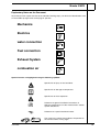
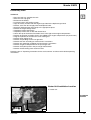
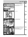
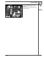
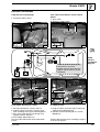
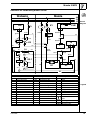
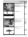
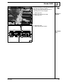
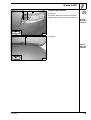
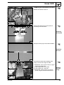
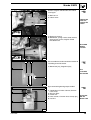
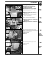
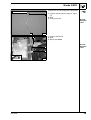
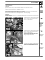
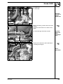
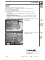
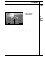
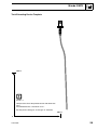
Water Heater Unit
Feel the drive
e1
Thermo Top E Auxiliary Heating
00 0003
e1
Thermo Top C Auxiliary Heating
00 0002
Installation Instructions
Mazda 3 MPS
Gasoline
From model year 2006
For left-hand drive vehicles only
WARNING!
Hazard warning:
Incorrect installation or repair of Webasto heating systems may cause a fire or result in the
emission of carbon monoxide, which can be fatal. Serious or fatal injuries can be caused as
a result.
Specialist company training, technical documentation, specialized tools and equipment are
required to install and repair Webasto heating and cooling systems.
NEVER attempt to install or repair Webasto heating or cooling systems if you have not
successfully completed the company training and thereby acquired the required technical
skills or if you do not have access to the required technical documentation, tools and
equipment needed to carry out correct installation and repairs.
ALWAYS follow all Webasto installation and repair instructions and observe all warning
instructions.
Webasto does not accept any liability for defects and damage that are attributable to an
installation by untrained staff.
Ident. No.: 1311472A
€10 fee
© Webasto AG
Mazda 3 MPS
Table of Contents
Validity
Heater Unit / Installation Kit
Foreword
General Instructions
Special Tools
Explanatory Notes on the Document
Preliminary Work
Heater Unit Installation Location
Preparing the Electronics
Electrical Connections
Automatic air conditioning blower control
Remote Start Option
2
3
3
3
3
4
5
5
6
8
9
12
Preparing the Installation Location
Installing the Heater Unit
Exhaust System
Fuel Connection
Combustion Air
Water Connection for Gasoline Engines
Final Work
Operating instructions for the end customer
Tank Extracting Device Template
13
15
17
18
21
22
26
27
28
Validity
Manufacturer
Mazda
Model
3 MPS
Type
BK
EG-BE No. / ABE
e1 * 2001 / 116 * 0234 * ...
Engine type
L3
Engine type
Gasoline
Power in kW
191
Engine capacity in cm³
2261
Vehicle and engine types, equipment variants as well as national specifications, which are not listed in
these installation instructions, have not been tested. Installation according to these installation
instructions may, however, be possible.
The installation location of a time switch and summer / winter switch should be confirmed with the end
customer before installation.
1311472A
2
Mazda 3 MPS
Heater Unit / Installation Kit
Amount
1
1
Description
Commercial supply of required control
Installation kit for Mazda 3 MPS Gasoline
Order no.:
See price list
1,311,467A
Recommended heater unit for the relevant vehicle class:
Vehicle
Compact car
Mid-class, station wagon
Luxury, van, off-roader
Heater unit
Thermo Top E
Thermo Top C
Thermo Top P
The choice of heater unit is based on the size of the vehicle passenger compartment and the
customer's comfort requirements.
Foreword
These installation instructions apply to Mazda vehicles with 3 MPS Gasoline – validity, see page 2 –
from model year 2006 and later, assuming technical modifications to the vehicle do not affect
installation, any liability claims excluded. Depending on the vehicle version and equipment,
modifications may be necessary during installation with respect to these installation instructions.
However, the stipulations in the "installation instructions" and "operating and maintenance instructions"
for the Thermo Top C/P/E are to be observed in any event.
The corresponding rules of technology and any information from the vehicle manufacturer should be
observed during the installation work.
General Instructions
Installation should be carried out according to the general, standard rules of technology. Unless
specified otherwise, fasten hoses, lines and cable harnesses to original vehicle lines and cable
harnesses using cable clips.
Sharp edges should be fitted with edge protectors (split open plastic hose).
Spray unfinished body areas, such as bore holes, with anti-corrosion wax (Tectyl 100K, Order no.
111329).
Special Tools
- Torque spanner for 2.0 - 10 Nm
- Vice-grip wrench
- Riveting nut tool
1311472A
3
Mazda 3 MPS
Explanatory Notes on the Document
To provide you with a quick overview of the individual working steps, you will find an identification mark
on the outside top right corner of the page in question.
Mechanics
Electrics
water connection
Fuel connection
Exhaust System
combustion air
Special features are highlighted using the following symbols:
Specific risk of injury or fatal accidents.
Specific risk of damage to components.
Specific risk of fire or explosion.
Reference to general installation instructions of
Webasto components or to the manufacturer's vehiclespecific documents.
Reference to a special technical feature.
The arrow in the vehicle icon indicates the position on
the vehicle and the viewing angle.
1311472A
4
Mazda 3 MPS
Preliminary Work
WARNING!
-
Open the tank cap, ventilate the tank.
Close the tank cap again.
Disconnect the battery.
Let off pressure in the cooling system.
Copy the factory number from the original type label to the duplicate type label.
Remove years that do not apply from the duplicate label.
Attach the duplicate label (type label) in the appropriate place.
Remove the engine design cover.
Completely remove the battery.
Completely remove the air filter with intake hose.
Loosen the top of the thermal insulation cover in the right of the engine compartment.
Remove the thermal insulation cover in the middle of the engine compartment (2x plastic nuts)
Hang the hydraulic oil container for servo steering out
Remove lower engine cover
Remove the panelling for the rear right axle
Remove fuel tank according to manufacturer's instructions
Remove tank mounting according to manufacturer's instructions.
Remove the glove compartment on the passenger side.
Remove the A-pillar panel in the passenger side footwell.
Remove the left cooling water reservoir cover
Remove page 27 "Operating instructions for the end customer" and insert with vehicle operating
instructions.
Heater Unit Installation Location
1 Heater unit
Installation
location
1
1311472A
1
5
Mazda 3 MPS
Preparing the Electronics
1
2
sw 2,5mm²
Only for automatic air conditioning
250mm
2250mm
3
4
1500mm
Wire section 4 will be needed later for
connecting the resistor.
br 2,5mm²
1000mm
5
Cutting
wires into
sections
sw 0,5mm²
1500mm
6
sw 0,5mm²
250mm
Wire sections
br
6
sw
2
85
30
Preassemble
the K3.1
relay
K3.1
86
sw
87a
87
sw
1
5
br
3
1
1 Thermal insulation cover
2 Edge protection profile
2
Inserting
edge
protection
2
Cut the accompanying flexible hose 1 in the
middle and pull on the ground cable for the
heater unit cable harness / ground cable
resistance 0.9 Ohm 2.
Connect the ground cable to ground 3.
Note the circuit diagram page 9.
1
3
1311472A
2
Ground
connection
3
6
Mazda 3 MPS
Put the remaining flexible hose 1 on the
positive cable on the heater unit cable
harness 2.
Connect the positive cable to the positive
battery terminal 3.
1
Positive
connection
2
3
1311472A
4
7
Mazda 3 MPS
Electrical Connections
Cable harness feed-through
Time switch and summer / winter switch
option
1 Protective rubber sleeve
1 Time switch
2 Summer / winter switch
1
1
2
5
6
rt
sw
br
bl
Cable
harness
installation
diagram
br
sw
sw
1
Wait to install the metering pump
cable harness until later,
together with fuel pipe along the
original vehicle fuel lines on the
underbody.
2
1
3
2
4
7
8
Fuse holder, K3 relay, K3.1 relay
0.9 Ohm resistor
1 K3 relay, M5x16 bolt, washers, M5 nut
2 Original vehicle stay bolts, fastening strap
bent according to the figure, M6 flanged nut
3 K3.1 relay fastened to the fastening strap
together with the K3 relay.
4 Fuse holder, M5x16 bolt, nut
Run the cables behind the thermal protection
panels.
1 Original vehicle stay bolts, body washer [2x],
angle bracket, M6flanged nut
2 0.9 Ohm resistor, M5 flanged nut, washer,
M5x20 bolt
1311472A
Connect 0.9 Ohm2 resistor according to page 9
in the circuit diagram.
8
Mazda 3 MPS
Automatic air conditioning blower control
Webasto
HG
X1
Mazda
K1
F3
F44
Circuit
diagram
PJB
J-03
4
rt/ws
86
sw/bl
rt
gn/ws
30
ge
0,5mm²
C-04
sw
ro/or
4mm²
87a
87
85
ge
0,5mm²
K3
B
sw
br
R1
br
4
30
75
15
sw/rt
sw
2
85
sw/or
ro/or
4mm²
sw
br
6
R
sw/gn
bl/sw
30
K3.1
86
87
sw
br
sw/gn
sw
M
87a
sw
G1
G2
1
3
5
31
Webasto components
HG
Heater unit TT-C/E
X1
6-pin connector
F3
Fuse, 25A
K3
Blower relay
K3.1 Supplementary relay
R1
0.9 Ohm resistor
Vehicle components
K1
Blower relay
C-04 Connector C-04
G1
blower motor
G2
Blower controller
B
air conditioning control
R
Radio unit
F44
Fuse, 7.5A
PJB
Colors and symbols
rt
red
ws
white
sw
black
br
brown
gn
green
bl
blue
or
orange
ro
pink
Legend
Fuse and relay support
X
Insulate and tie back wire
ends
Splitting point
Cable colors may vary.
1311472A
9
Mazda 3 MPS
Connection to the connector 3 C-04
Connect with enclosed connectors according
to the circuit diagram.
2
1
3
1
2
4
5
Wire (sw) from K3/30
Pink/orange (ro/or) wire to blower motor.
Pink/orange (ro/or) wire to connector C-04.
Red (rt) wire from F3/87a
5
Positive
connection
to the
blower
motor
9
4
1 Connector C-04
2 Pink/orange (ro/or) slot.
2
1
Connector
C-04
10
1
2
Connection to 6-pin connector 4 from the
blower control.
3
1
2
3
5
5
Brown (br) wire from K3.1/87
Black/green (sw/gn) wire
Black (sw) wire from K3.1/87a
Black/green (sw/gn) wire
Positive
connection
to the
blower
motor
11
4
Connection to 6-pin connector 1 from the
blower control.
2 Black/green (sw/gn) wire
1
2
1311472A
Blower
controller
connector
12
10
Mazda 3 MPS
1
2
3
Pull the connection to connector 5 J-03 from
the PJB fuse and relay support.
Connect with enclosed butt connector 3
according to the circuit diagram.
1 Yellow (ge) wire
2 Black (sw) wire from K3.1/86
4 Yellow (ge) wire
Relay K3.1
control
4
5
13
1 Connector J-03
2 Yellow (ge) plug-in position
1
Connector
J-03
2
1311472A
14
11
Mazda 3 MPS
1
2
Remote Start Option
3
1 Receiver
2 Bracket, drill hole in bracket to Ø6.5mm.
3 M6x12 bolt, original vehicle threaded insert
Assembling the
receiver
15
1 Antenna
1
Assembling the
antenna
16
1311472A
12
Mazda 3 MPS
Preparing the Installation Location
1
Remove the blower resistor 1
17
Drill Ø 7mm holes1 [2x] in the bracket 2
according to the illustration.
1
1
107mm
114mm
30mm
Preparing
the bracket
18mm
2
18
Drill open holes 1[2x] in the strut 2 to Ø10mm.
1
1
19
2
1
5
Preparing
the strut
2
Assemble the bracket 2 according to the
image, transfer hole images 3 and 4.
3
4
1 M6x20 bolt, 5 mm spacer washer, original
vehicle threaded insert
3 Hole image for Ø 9.1 mm hole
4 Hole image for Ø 7 mm hole
5 M6x70 bolt, 15mm spacer nut, 30 mm
spacer, original vehicle threaded insert
Copying
the hole
image
20
1311472A
13
Mazda 3 MPS
Remove original vehicle bolt 2, this will be
used again.
1
1 M6 rivet nut
3 Hole Ø 7mm
2
Tighten the
rivet nut;
remove the
screw
3
21
1 Blower resistance
2 M6x20 bolt, spring washer, body washer,
8mm spacer washer, original vehicle
threaded insert
1
Assemble
blower
resistor
22
2
1
Preassemble the bracket 3 with the bracket 2
according to the illustration.
1
1 M6x12 bolt [4x], flanged nut [4x]
3
Preassemble
the bracket
2
1
1
23
Ejot screw bolt tightening torque 10 Nm!
5
1
1 Combustion air intake silencer, Ø27mm
hose clamp
2 Ejot stay bolts
3 Heater unit
4 Hose section, Ø 10 mm hose clamps [2x]
5 Fuel line
4
3
Preassemble the
Heater Unit
2
24
1311472A
14
Mazda 3 MPS
1
Installing the Heater Unit
2
6
3
5
4
Assemble the pre-assembled bracket
according to the illustration.
Resistor retaining plate 1 is assembled
together with the bracket 3, spring washer 6,
body washer 6, spacer 5mm 6, original
vehicle threaded insert 6.
Assembling the
bracket
2 M6x20 bolt, spring washer, rivet nut
4 M6x70 bolt, 20 mm spacer, 30 mm spacer,
M6 flanged nut
5 M6x70 bolt, 15mm spacer nut, 30 mm
spacer, M6 flanged nut
25
1
Figure 18 is the rear view of figure 17.
2
1 M6x70 bolt, 20 mm spacer, 30 mm spacer,
M6 flanged nut
2 M6x70 bolt, 15mm spacer, 30 mm spacer,
M6 flanged nut
3 Bracket
Assembling the
bracket
3
26
1
Ejot screw bolt tightening torque 10 Nm!
Before assembling the heater unit 3, plug the
header unit cable harness.
2
1 Ejot screw bolt
2 Bracket
3
Assembling the
Heater Unit
27
Ejot screw bolt tightening torque 10 Nm!
1
1 Ejot screw bolt
2 Bracket
Assembling the
strut
2
28
1311472A
15
Mazda 3 MPS
Prepare the strut according to the illustration
3
1
1 Original vehicle bolt [see page 14, figure
21]
2 Strut
3 5mm spacer disc
Assembling the
strut
29
2
1 Original vehicle bolt
2 Strut
3 Spacer nut M6x30
1
2
Assembling the
strut
3
30
1311472A
16
Mazda 3 MPS
1
Exhaust System
2
1 Exhaust pipe
a = 440mm
2 Exhaust end section
b = 50mm
Dispose of section X
a
Preparing
the
exhaust
pipe
b
X
1
Ensure sufficient distance from adjacent
components.
2
3
4
5
6
7
1311472A
1 Hose bracket
2 Exhaust line, hose clamp on the exhaust
silencer [covered]
3 Heat insulation
4 M6x16 bolt, spring washer
5 Exhaust silencer
6 Exhaust end section, hose clamp
7 Red (rt) rubber profile with groove
Assembling the
silencer
31
17
Mazda 3 MPS
Fuel Connection
CAUTION!
Open the vehicle's tank-cap lock, ventilate the tank and then re-close the tank lock.
Catch any fuel running off with an appropriate container.
Install fuel line and metering pump cable harness so that they are protected against stone impact.
Unless specified otherwise, always fasten using cable clips.
Fit the fuel line and cable harness with edge protectors around sharp edges.
WARNING!
The fuel line and cable harness to the metering pump should be installed based on the cable harness
installation diagram.
Install the fuel line 1 and the heater unit cable
harness 2 on the original vehicle fuel lines
and secure with cable ties.
7
Placement
of the fuel
line in the
engine
compartment
1
2
32
1
Install the fuel line 1 and the heater unit cable
harness 2 on the original vehicle fuel lines
and secure with cable ties.
Run this along the right side of the vehicle,
behind the thermal insulation covers and
along the original vehicle lines.
2
Placing the
fuel pipe
33
1
2
Placement of the fuel pipe 2 is done together
with the metering pump cable harness 1 to
the vehicle underbody behind the insulation
3.
3
Placing the
fuel pipe
34
1311472A
18
Mazda 3 MPS
1
Placement of the fuel pipe 2 is done together
with the metering pump cable harness 1 to
the vehicle underbody along the original
vehicle lines, secure with cable ties.
2
Placing the
fuel pipe
35
Installation location of the metering pump 1 is
to the right next to the vehicle tank.
Run the fuel pipe from the heater unit 2 and
metering pump cable harness 3 to the
metering pump installation location 1.
1
Placing the
fuel pipe
3
1
2
2
36
Fuel pipe 6 from the heater unit on the outake
side of the metering pump 3 [side with
connector].
Check the position of the components; adjust
if necessary. Check that they have free
clearance.
3
7
1 Fastening strap with holes
2 Rubber tube clamp, silentblock, flanged
nut M6 [2x]
4 Metering pump cable harness, connector
5 Hose section, hose clamps [2x].
7 Original vehicle bolt, loosely fitted
6
5
1
Assembling the
metering
pump
37
4
Remove the tank mounting according to the
manufacturer's instructions and take it apart.
Attach the M6 flanged nut 2 according to the
illustration, transfer the hole image for the Ø
6.0 mm hole.
2
1 Tank mounting
Fuel takeoff
38
1311472A
19
Mazda 3 MPS
Shape, cut into sections, and insert the tank
extracting device according to the template,
see the Installation Instructions.
Re-assemble tank mounting!
1
2
1 Tank extracting device
2 Tank mounting
Inserting
tank
extracting
device
39
Install the tank mounting according to
manufacturer's instructions.
1 Fuel line 1500 mm
2 Hose section, Ø 10 mm hose clamps [2x]
3 Tank extracting device
2
3
1
40
1
2
Connecting and
disconnecting the
fuel pipe
Assemble fuel tank according to
manufacturer's instructions.
Fuel line from the tank extracting device on
the intake side of the metering pump 1 [side
without connector].
Check the position of the components; adjust
if necessary. Check that they have free
clearance.
3
2 Hose section, Ø 10mm hose clamps [2x]
3 Fuel pipe, cut into sections
Connection to
metering
pump
41
Assemble the panelling on the rear axle 1.
1
2 Original vehicle bolt (see page 19 figure
37).
Assembling the
panelling
for the rear
axle
2
42
1311472A
20
Mazda 3 MPS
Combustion Air
Run the combustion air line 1 according to the
figure.
Placement
of the
combustion air line
43
1
Note the spatial requirements for the engine
filter housing.
Fasten the intake silencer 3 to the cable
harness 2with cable ties1.
1
2
3
4
1311472A
1 Combustion air intake pipe
Assemble
the intake
silencer
44
21
Mazda 3 MPS
Water Connection for Gasoline Engines
WARNING!
Tighten all hose clamps to 2.0 + 0.5 Nm.
Any coolant running off should be collected using an appropriate container!
Route hoses so that they are kink-free. Unless specified otherwise, always fasten using cable clips.
Position hose clamps and spring band clamps so that no other hose can be damaged.
The connection should be "inline" based on the following diagram:
Water
installation
diagram
A
Ø 17x20
Ø 18x18
C
1
B
All hose clamps = Ø 20-27 mm.
All undesignated connecting pipes = Ø 18x20.
1 = Rubber profile (sw)
1311472A
22
Mazda 3 MPS
b = 450mm
c = 660mm
C
B
Dispose of section X
Cut the braided protective hose into sections
and slide it onto hose B and hose C.
X
b
X
c
Cutting
water
hoses into
sections
A
Cut the braided protective hose in the middle
and slide it onto hose B and hose C.
Cut shrink-fit hose to size.
B
1
1
1 25 mm shrink-fit hose [4x]
2 Black (sw) rubber profile
2
150
1
Preparing
the water
hoses
1
C
Turn the original vehicle clamp 1 down.
1
45
1
2
Remove the hose coating 3 from the engine
exhaust hose 2.
3
1 Turn the original vehicle clamp up.
Preparing
the
splitting
point
60mm
46
1311472A
23
Mazda 3 MPS
1 Original vehicle engine exhaust hose
2 Cut location
2
1
Splitting
point
47
1
1 Engine exhaust hose section
A
Connection of
moulded
hose A:
48
1 Heater unit
B
Connecting hose B
on the
heater unit
1
49
Align the rubber profile 1.
1
Connecting hose B
to moulded
hose A
A
B
1311472A
50
24
Mazda 3 MPS
C
1 Heater unit
2 Cable clips
1
2
Connecting hose C
on the
heater unit
51
Before connecting, fill the water hoses with
coolant.
Insert the hose bracket 1 as shown in the
figure.
1
B
2 Heat exchanger inlet hose section
2
52
C
1
Connecting to the
heat
exchanger
inlet
C
Prepare the water hoses with cable clips 1
according to the figure.
B
Hose
placement
1
53
1311472A
25
Mazda 3 MPS
Final Work
WARNING!
Reassemble disassembled components in reverse order.
Check that all hose lines, clips, and all electrical connections are securely fastened.
Secure all loose cables using cable clips.
Only use manufacturer-approved coolant.
Spray heating unit components with anti-corrosion wax (Tectyl 100K, Order No. 111329).
-
Connect battery.
Fill and bleed the coolant circuit according to the vehicle manufacturer’s specifications.
Set the time switch.
Set the manual air conditioning or automatic air conditioning according to the "operating
instructions for the end customer".
- Check that the auxiliary heating operates properly, see operating instructions / installation
instructions.
- Attach the "Switch off auxiliary heating before re-fuelling" sticker onto the left side of the B-pillar.
1 Hole Ø 42mm
2 Lower engine cover
1
2
Cut out the
underride
protection
54
Assemble the lower engine cover 1, insert red
rubber profile with nut 2.
1
Inserting
rubber
profile
2
55
Feel the drive
Webasto AG
PO Box 80 - 82132 Stockdorf
Hotline 01805 / 932278 - Hotfax 0395 / 5592-353
http://www.webasto.de
1311472A
Printed in Germany
10/2006
Press: Steffen
Mazda 3 MPS
Operating instructions for the end customer
Please remove page and add to the vehicle operating instructions.
Before parking the vehicle, make the following settings:
1 Blower rpm is pre-set in auxiliary heating
operation
2 Air outlet to windscreen
3 Temperature to "max."
For
vehicles
with
automatic
air
conditioning
1
2
3
56
For short distance trips, it is not recommended that the rear window heating be used.
Rule of thumb for operating the auxiliary heating: driving time = heating time.
1311472A
27
Mazda 3 MPS
Tank Extracting Device Template
100mm
Scale 1:1
Compare the size of the printed version with dimension
lines.
Permitted tolerance a maximum of 2%.
Set the printer settings to “no margin” or “minimize
100mm
0
1311472A
28